 Datasheet下载
- 型号: C340C104K2R5TA
- 制造商: Kemet
- 库位|库存: xxxx|xxxx
- 要求:
| 数量阶梯 | 香港交货 | 国内含税 |
| +xxxx | $xxxx | ¥xxxx |
查看当月历史价格
查看今年历史价格
C340C104K2R5TA产品简介:
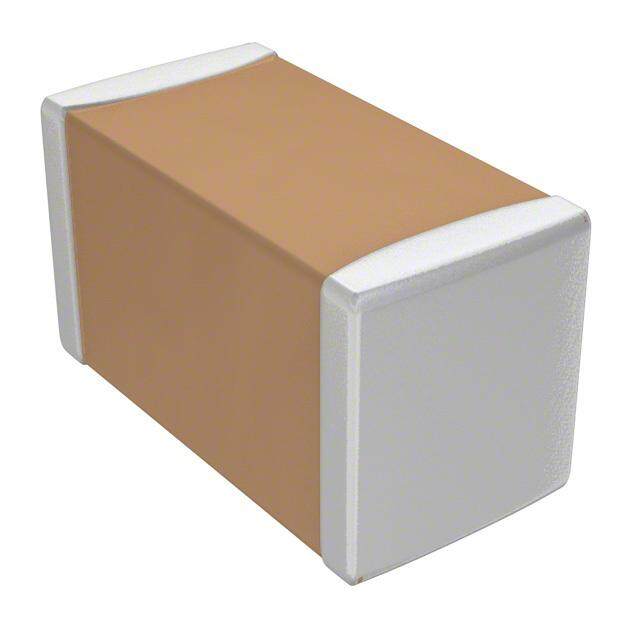
ICGOO电子元器件商城为您提供C340C104K2R5TA由Kemet设计生产,在icgoo商城现货销售,并且可以通过原厂、代理商等渠道进行代购。 C340C104K2R5TA价格参考¥3.75-¥3.75。KemetC340C104K2R5TA封装/规格:陶瓷电容器, 0.1µF ±10% 200V 陶瓷电容器 X7R 径向。您可以下载C340C104K2R5TA参考资料、Datasheet数据手册功能说明书,资料中有C340C104K2R5TA 详细功能的应用电路图电压和使用方法及教程。
KEMET的C340C104K2R5TA是一款多层陶瓷电容器(MLCC),其主要参数为100nF(104表示100nF)、误差±10%(K级)、额定电压25V(2R5表示25V)、温度特性为X7R(工作温度范围-55℃至+125℃),适用于广泛的工作环境。

该电容器常用于以下应用场景:

1. 去耦与旁路应用:在电源管理系统中,用于滤除高频噪声、稳定电压,保障集成电路(IC)稳定运行,常见于数字电路和微处理器供电系统。

2. 消费电子产品:如智能手机、平板电脑、电视及机顶盒等设备中,作为电源管理模块或信号处理电路中的滤波元件。

3. 工业控制系统:用于PLC、传感器模块、自动化设备中的电源稳压与信号调理电路。

4. 通信设备:在路由器、交换机、基站模块中用作滤波器或耦合元件,提升信号完整性。

5. 汽车电子:符合AEC-Q200标准的部分应用,可用于车载电源、控制单元、娱乐系统等非关键性电路中。

6. 医疗设备:用于低风险等级的诊断或监测设备中,提供稳定的电容性能。

该型号因具备高可靠性、小体积和良好的频率响应特性,广泛应用于对空间和性能有要求的电子设计中。
| 参数 | 数值 |
| 产品目录 | |
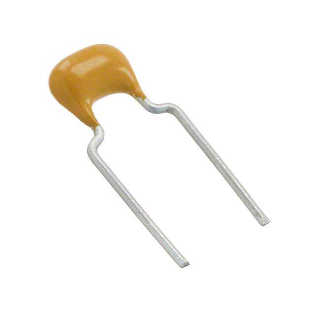
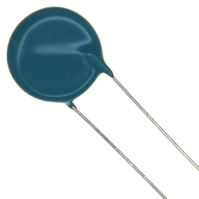
| 描述 | CAP CER 0.1UF 200V 10% RADIAL多层陶瓷电容器MLCC - 含引线 C340 0.1uF 200volts X7R 10% |
| 产品分类 | |
| 品牌 | Kemet |
| 产品手册 | |
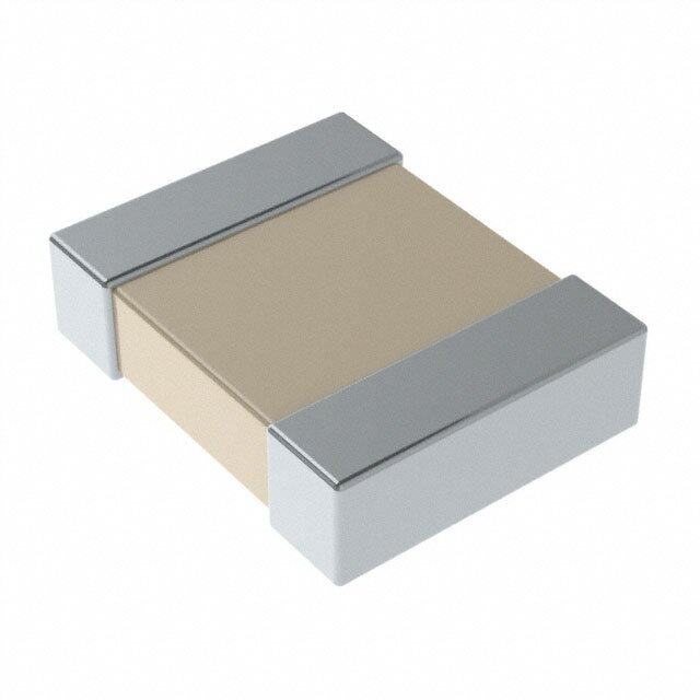
| 产品图片 |
|
| rohs | RoHS 合规性豁免无铅 / 符合限制有害物质指令(RoHS)规范要求 |
| 产品系列 | MLCC,多层陶瓷电容器MLCC - 含引线,Kemet C340C104K2R5TAGolden Max™ |
| 数据手册 | http://www.kemet.com/docfinder?Partnumber=C340C104K2R5TA |
| 产品型号 | C340C104K2R5TA |
| 产品 | General Type MLCCs |
| 产品培训模块 | http://www.digikey.cn/PTM/IndividualPTM.page?site=cn&lang=zhs&ptm=25569 |
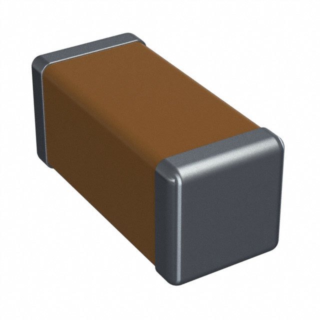
| 产品目录绘图 |
|
| 产品目录页面 | |
| 产品种类 | 多层陶瓷电容器MLCC - 含引线 |
| 其它名称 | 399-4425 |
| 包装 | 散装 |
| 厚度(最大值) | - |
| 商标 | Kemet |
| 外壳宽度 | 10.16 mm |
| 外壳长度 | 11.68 mm |
| 外壳高度 | 3.81 mm |
| 大小/尺寸 | 0.400" 长 x 0.150" 宽(10.16mm x 3.81mm) |
| 安装类型 | 通孔 |
| 容差 | ±10% |
| 封装 | Bulk |
| 封装/外壳 | 径向 |
| 封装类型 | Conformally Coated |
| 工作温度 | -55°C ~ 125°C |
| 工作温度范围 | - 55 C to + 125 C |
| 工厂包装数量 | 100 |
| 应用 | 通用 |
| 引线形式 | 直形 |
| 引线直径 | 0.51 mm |
| 引线类型 | Straight |
| 引线间距 | 0.200"(5.08mm) |
| 引线间隔 | 5.08 mm |
| 损耗因数DF | 2.5 |
| 最大工作温度 | + 125 C |
| 最小工作温度 | - 55 C |
| 标准包装 | 100 |
| 温度系数 | X7R |
| 温度系数/代码 | X7R |
| 特性 | - |
| 电压-额定 | 200V |
| 电压额定值 | 200 V |
| 电压额定值DC | 200 V |
| 电容 | 0.1µF |
| 端接类型 | Radial |
| 等级 | - |
| 类型 | Radial Leads |
| 系列 | C340 |
| 高度-安装(最大值) | 0.460"(11.68mm) |


- 商务部:美国ITC正式对集成电路等产品启动337调查
- 曝三星4nm工艺存在良率问题 高通将骁龙8 Gen1或转产台积电
- 太阳诱电将投资9.5亿元在常州建新厂生产MLCC 预计2023年完工
- 英特尔发布欧洲新工厂建设计划 深化IDM 2.0 战略
- 台积电先进制程称霸业界 有大客户加持明年业绩稳了
- 达到5530亿美元!SIA预计今年全球半导体销售额将创下新高
- 英特尔拟将自动驾驶子公司Mobileye上市 估值或超500亿美元
- 三星加码芯片和SET,合并消费电子和移动部门,撤换高东真等 CEO
- 三星电子宣布重大人事变动 还合并消费电子和移动部门
- 海关总署:前11个月进口集成电路产品价值2.52万亿元 增长14.8%


PDF Datasheet 数据手册内容提取
Radial Leaded Multilayer Ceramic Capacitors Goldmax, 300 Series, Conformally Coated, X7R Dielectric, 25 – 250 VDC (Commercial Grade) Overview KEMET’s Goldmax conformally coated radial leaded ceramic exhibits a predictable change in capacitance with respect to time capacitors in X7R dielectric feature a 125°C maximum and voltage and boasts a minimal change in capacitance with operating temperature. The Electronics Industries Alliance reference to ambient temperature. Capacitance change is limited (EIA) characterizes X7R dielectric as a Class II "temperature to ±15% from −55°C to +125°C. stable" material. Components of this classification are fixed, ceramic dielectric capacitors suited for bypass and decoupling These devices meets the flame test requirements outlined in applications or for frequency discriminating circuits where Q UL Standard 94V–0. and stability of capacitance characteristics are not critical. X7R Benefits • Radial leaded form factor • Conformally coated • 0.100", 0.200", 0.250" and 0.400" lead spacing • −55°C to +125°C operating temperature range • Lead (Pb)-free, RoHS and REACH compliant • X7R temperature stable dielectric Ordering Information C 320 C 106 K 3 R 5 T A 7301 Specification/ Capacitance Capacitance Rated Voltage Lead Failure Packaging Ceramic Style/Size Dielectric Design Series Code (pF) Tolerance1 (VDC) Finish2 Rate (C-Spec) 315 324 335 C = First two digits J = ±5% 3 = 25 R = 5 = T = 100% A = See 316 325 336 Standard represent K = ±10% 5 = 50 X7R Multilayer Matte Sn N/A "Packaging 317 326 340 significant M = ±20% 1 = 100 H = SnPb C-Spec 318 327 346 figures. Third 2 = 200 (60/40) Ordering 320 328 350 digit specifies A = 250 Options 321 330 356 number of zeros. Table" 322 331 below 323 333 1 Additional capacitance tolerance offerings may be available. Contact KEMET for details. 2 Lead materials: Standard: 100% matte tin (Sn) with nickel (Ni) underplate and steel core ( “T” designation). Alternative 1: 60% tin (Sn)/40% lead (Pb) finish with copper-clad steel core ( “H” designation). Alternative 2: 60% tin (Sn)/40% lead (Pb) finish with 100% copper core (available with “H” designation code with C-Spec). Contact KEMET for C-Spec details. One world. One KEMET © KEMET Electronics Corporation • KEMET Tower • One East Broward Boulevard C1050_GOLDMAX_X7R • 1/28/2020 1 Fort Lauderdale, FL 33301 USA • 954-766-2800 • www.kemet.com
Radial Leaded Multilayer Ceramic Capacitors Goldmax, 300 Series, Conformally Coated, X7R Dielectric, 25 – 250 VDC (Commercial Grade) Benefits cont. • DC voltage ratings of 25 V, 50 V, 100 V, 200 V and 250 V • Capacitance offerings ranging from 100 pF to 10 μF • Available capacitance Tolerances of ±5%, ±10% and ±20% • Non-polar device, minimizing installation concerns • 100% pure matte tin-plated lead finish allowing for excellent solderability • SnPb-plated lead finish option available upon request (Sn60/Pb40) • Encapsulation meets flamability standard UL 94V–0 Applications Typical applications include decoupling, bypass, filtering and transient voltage suppression. Application Notes These devices are not recommended for use in overmold applications and/or processes. Packaging C-Spec Ordering Options Table Packaging Type1 Packaging/Grade Ordering Code (C-Spec) Bulk Bag Not required (Blank) 12" Tape & Reel (16.0 ± 0.5 mm lead length) 7301 12" Tape & Reel (18.0 mm minimum lead length) 7303 and TR Ammo Pack (16.0 ± 0.5 mm lead length) 7305 Ammo Pack (18.0 mm minimum lead length) 7317 1 Default packaging is "Bulk Bag". An ordering code C-Spec is not required for "Bulk Bag" packaging. Bulk bag option is required for Size/Style C321 and C331. 1 "Tape and Reel" packaging option is not available for Size/Style C321 and C331. For more information see "Packaging Quantities". 1 "Ammo Pack" packaging option is not available for Size/Style C321, C331, C350 and C356. For more information see "Packaging Quantities". 1 "Ammo Pack" and "Tape and Reel" packaging options have the same lead tape configuration. For more information see "Tape & Reel Packaging Information". Qualification/Certification Commercial Grade products are subject to internal qualification. Details regarding test methods and conditions are referenced in Table 2, Performance & Reliability. © KEMET Electronics Corporation • KEMET Tower • One East Broward Boulevard C1050_GOLDMAX_X7R • 1/28/2020 2 Fort Lauderdale, FL 33301 USA • 954-766-2800 • www.kemet.com
Radial Leaded Multilayer Ceramic Capacitors Goldmax, 300 Series, Conformally Coated, X7R Dielectric, 25 – 250 VDC (Commercial Grade) Dimensions – Inches (Millimeters) Shoulder Bend (Short) Shoulder Bend (Tall) Inside Kink Straight L T L T L T L T C315 C317 C330* C318 C320 C321 C331* H C323 C333 C340: C330* H C322 CC334500* C328 H H (02..1504 mmamx) CC333410** Seating Plane All Others: 0.06 max (1.52 mm) LL LL Seating Plane Seating Plane F F LL F LL F S S S S Outside Kink Snap-In Type 2 Snap-In Type 1 L T L T L T C316 C326 C327 C325 CC333466 H C324 H C335 H C356 Seating Plane Seating Plane Seating Plane LL LL LL *c oMnafiyg ubrea stiuopnp. lPieleda isne a s “eSeh Coaupldaecri tBaenncde” R oarn “gSet rWaiagthetr”f aLlel asde ction F F F of this document to determine lead configuration availability by S S S capacitance value. E E F S L H T LL Style / Lead Diameter Series Lead Spacing Length Height Thickness Lead Length Size +0.004 (0.10), ±0.030 (0.78) Maximum Maximum Maximum Minimum −0.001 (0.025) 315 0.150 (3.81) 0.120 (3.14) 0.100 (2.54) 0.276 (7.00) C31X 316 0.150 (3.81) 0.230 (5.84) 0.100 (2.54) 0.200 (5.08) 324 0.100 (2.54) 0.200 (5.08) 0.230 (5.84) 0.125 (3.18)1 0.276 (7.00) C32X 320 0.200 (5.08) 0.230 (5.84) 0.125 (3.18)1 0.276 (7.00) 326 0.200 (5.08) 0.300 (7.62) 0.125 (3.18)1 0.200 (5.08) 317 0.150 (3.81) 0.200 (5.08) 0.100 (2.54) 0.276 (7.00) C31X 0.200 (5.08) 318 0.150 (3.81) 0.235 (5.97) 0.100 (2.54) 0.276 (7.00) 321 0.250 (6.35) 0.200 (5.08) 0.260 (6.60) 0.125 (3.18)1 0.276 (7.00) 322 0.200 (5.08) 0.260 (6.60) 0.125 (3.18)1 0.276 (7.00) 323 0.200 (5.08) 0.300 (7.62) 0.125 (3.18)1 0.276 (7.00) C32X 0.020 (0.51) 325 0.200 (5.08) 0.300 (7.62) 0.125 (3.18)1 0.276 (7.00) 0.200 (5.08) 328 0.200 (5.08) 0.300 (7.62) 0.125 (3.18)1 0.276 (7.00) 327 0.200 (5.08) 0.320 (8.13) 0.125 (3.18)1 0.200 (5.08) 330 0.280 (7.11) 0.360 (9.14) 0.160 (4.07) 0.276 (7.00) 331 0.250 (6.35) 0.280 (7.11) 0.360 (9.14) 0.160 (4.07) 0.276 (7.00) C33X 333 0.280 (7.11) 0.400 (10.16) 0.160 (4.07) 0.276 (7.00) 335 0.280 (7.11) 0.400 (10.16) 0.160 (4.07) 0.276 (7.00) 336 0.200 (5.08) 0.280 (7.11) 0.400 (10.16) 0.160 (4.07) 0.200 (5.08) 340 0.290 (7.36) 0.400 (10.16) 0.160 (4.07) 0.276 (7.00) C34X 346 0.290 (7.36) 0.400 (10.16) 0.160 (4.07) 0.200 (5.08) 350 0.330 (8.38) 0.400 (10.16) 0.200 (5.08) 0.276 (7.00) C35X 0.400 (10.16) 0.025 (0.64) 356 0.330 (8.38) 0.400 (10.16) 0.200 (5.08) 0.200 (5.08) 1 Thickness maximum (T) = 0.160" (4.07 mm) for capacitance values greater than or equal to 4.7 µF © KEMET Electronics Corporation • KEMET Tower • One East Broward Boulevard C1050_GOLDMAX_X7R • 1/28/2020 3 Fort Lauderdale, FL 33301 USA • 954-766-2800 • www.kemet.com
Radial Leaded Multilayer Ceramic Capacitors Goldmax, 300 Series, Conformally Coated, X7R Dielectric, 25 – 250 VDC (Commercial Grade) Environmental Compliance Lead (Pb)-free, REACH and RoHS compliant without exemptions when ordered with a 100% tin (Sn) wire lead finish. Product ordered with tin/ lead (Sn60/Pb40) wire lead finish do not meet RoHS criteria. Termination RoHS RoHS REACH Halogen Series Finish Exemption Compliant Compliant1 Free (Wire Lead) Code 100% Matte Sn Yes n/a Yes Yes 300 (C3XX) Sn60/Pb40 No n/a Yes Yes 1 REACH compliance indicates product does not contain Substance/s of Very High Concern (SVHC) Electrical Parameters/Characteristics Item Parameters/Characteristics Operating Temperature Range −55°C to +125°C Capacitance Change with Reference to ±15% +25°C and 0 VDC Applied (TCC) Aging Rate (Maximum % Cap Loss/Decade Hour) 3.0% 250% of rated voltage Dielectric Withstanding Voltage (5±1 second and charge/discharge not exceeding 50 mA at 25ºC) Dissipation Factor (DF) Maximum Limit at 25ºC See Dissipation Factor Limit Table See Insulation Resistance Limit Table Insulation Resistance (IR) Limit at 25°C (Rated voltage applied for 120±5 seconds at 25°C) Regarding Aging Rate: Capacitance measurements (including tolerance) are indexed to a referee time of 48 or 1,000 Hours. Please refer to a part number specific datasheet for referee time details. To obtain IR limit, divide MΩ-µF value by the capacitance and compare to GΩ limit. Select the lower of the two limits. Capacitance and dissipation factor (DF) measured under the following conditions: 1 kHz ±50 Hz and 1.0 ±0.2 V rms Note: When measuring capacitance it is important to ensure the set voltage level is held constant. The HP4284 and Agilent E4980 have a feature known as Automatic Level Control (ALC). The ALC feature should be switched to "ON." Insulation Resistance Limit Table 1,000 megohm microfarads 500 megohm microfarads 100 Megohm Style/Size or 100GΩ or 10GΩ Microfarads or 10GΩ C31X < 0.12 μF ≥ 0.12 μF NA C32X < 0.18 μF NA ≥ 0.18 μF C33X < 0.18 μF NA ≥ 0.18 μF C34X < 1.20 μF ≥ 1.20 μF NA C35X < 2.70 μF ≥ 2.70 μF NA © KEMET Electronics Corporation • KEMET Tower • One East Broward Boulevard C1050_GOLDMAX_X7R • 1/28/2020 4 Fort Lauderdale, FL 33301 USA • 954-766-2800 • www.kemet.com
Radial Leaded Multilayer Ceramic Capacitors Goldmax, 300 Series, Conformally Coated, X7R Dielectric, 25 – 250 VDC (Commercial Grade) Post Environmental Limits High Temperature Life, Biased Humidity and Storage Life Rated Capacitance Dissipation Factor Capacitance Insulation Style/Size DC Voltage Value (Maximum %) Shift Resistance 25 All 5.0 C31X < 1.0 μF 3.0 > 25 ≥ 1.0 μF 20.0 25 < 2.2 μF 5.0 10% of Initial ±20% C32X, C33X, Limit > 25 < 2.2 μF 3.0 C34X 25/50 ≥ 2.2 μF 20.0 25 5.0 C35X All > 25 3.0 Dissipation Factor (DF) Limit Table Rated Rated Dissipation Factor Style/Size DC Voltage Capacitance (Maximum %) 25 All 3.5 C31X < 1.0 μF 2.5 > 25 ≥ 1.0 μF 10.0 25 < 2.2 μF 3.5 C32X, C33X, C34X > 25 < 2.2 μF 2.5 25 / 50 ≥ 2.2 μF 10.0 25 3.5 C35X All > 25 2.5 © KEMET Electronics Corporation • KEMET Tower • One East Broward Boulevard C1050_GOLDMAX_X7R • 1/28/2020 5 Fort Lauderdale, FL 33301 USA • 954-766-2800 • www.kemet.com
Radial Leaded Multilayer Ceramic Capacitors Goldmax, 300 Series, Conformally Coated, X7R Dielectric, 25 – 250 VDC (Commercial Grade) Table 1A – C31X Style/Size, Capacitance Range Waterfall C315, C316, C317, C318 Style/Size (0.100" and 0.200" Lead Spacing) Rated Voltage (VDC) 25 50 100 200 250 Voltage Code 3 5 1 2 A Capacitance Capacitance Capacitance Code (Available Capacitance) Tolerance 100pF 101 101 101 101 101 120pF 121 121 121 121 121 150pF 151 151 151 151 151 180pF 181 181 181 181 181 220pF 221 221 221 221 221 270pF 271 271 271 271 271 330pF 331 331 331 331 331 390pF 391 391 391 391 391 470pF 471 471 471 471 471 560pF 561 561 561 561 561 680pF 681 681 681 681 681 820pF 821 821 821 821 821 1000pF 102 102 102 102 102 1200pF 122 122 122 122 122 1500pF 152 152 152 152 152 1800pF 182 182 182 182 182 2200pF 222 222 222 222 222 2700pF 272 272 272 272 272 3300pF 332 332 332 332 332 3900pF 392 392 392 392 392 4700pF 472 472 472 472 472 5600pF 562 562 562 562 562 6800pF 682 682 682 682 682 J = ±5% 8200pF 822 822 822 822 822 K = ±10% 0.01µF 103 103 103 103 103 M = ±20% 0.012µF 123 123 123 123 123 0.015µF 153 153 153 153 153 0.018µF 183 183 183 183 183 0.022µF 223 223 223 223 223 0.027µF 273 273 273 273 273 0.033µF 333 333 333 333 333 0.039µF 393 393 393 393 393 0.047µF 473 473 473 473 473 0.056µF 563 563 563 563 563 0.068µF 683 683 683 0.082µF 823 823 823 0.1µF 104 104 104 0.12µF 124 124 124 0.15µF 154 154 154 0.18µF 184 184 184 0.22µF 224 224 224 0.27µF 274 274 0.33µF 334 334 0.39µF 394 394 0.47µF 474 474 0.56µF 564 564 0.68µF 684 684 1.0µF 105 105* Rated Voltage (VDC) 25 50 100 200 250 Voltage Code 3 5 1 2 A * Only available on K and M tolerances. © KEMET Electronics Corporation • KEMET Tower • One East Broward Boulevard C1050_GOLDMAX_X7R • 1/28/2020 6 Fort Lauderdale, FL 33301 USA • 954-766-2800 • www.kemet.com
Radial Leaded Multilayer Ceramic Capacitors Goldmax, 300 Series, Conformally Coated, X7R Dielectric, 25 – 250 VDC (Commercial Grade) Table 1B – C32X Style/Size, Capacitance Range Waterfall C320, C322, C323, C326, C328 Style/Size (0.100" and 0.200" Lead Spacing) Rated Voltage (VDC) 25 50 100 200 250 Voltage Code 3 5 1 2 A Capacitance Capacitance Capacitance Code (Available Capacitance) Tolerance 100pF 101 101 101 101 101 120pF 121 121 121 121 121 150pF 151 151 151 151 151 180pF 181 181 181 181 181 220pF 221 221 221 221 221 270pF 271 271 271 271 271 330pF 331 331 331 331 331 390pF 391 391 391 391 391 470pF 471 471 471 471 471 560pF 561 561 561 561 561 680pF 681 681 681 681 681 820pF 821 821 821 821 821 1000pF 102 102 102 102 102 1200pF 122 122 122 122 122 1500pF 152 152 152 152 152 1800pF 182 182 182 182 182 2200pF 222 222 222 222 222 2700pF 272 272 272 272 272 3300pF 332 332 332 332 332 3900pF 392 392 392 392 392 4700pF 472 472 472 472 472 5600pF 562 562 562 562 562 6800pF 682 682 682 682 682 8200pF 822 822 822 822 822 0.01µF 103 103 103 103 103 0.012µF J = ±5% 123 123 123 123 123 0.015µF K = ±10% 153 153 153 153 153 0.018µF M = ±20% 183 183 183 183 183 0.022µF 223 223 223 223 223 0.027µF 273 273 273 273 273 0.033µF 333 333 333 333 333 0.039µF 393 393 393 393 393 0.047µF 473 473 473 473 473 0.056µF 563 563 563 563 563 0.068µF 683 683 683 683 683 0.082µF 823 823 823 823 823 0.1µF 104 104 104 104 104 0.12µF 124 124 124 124 124 0.15µF 154 154 154 154 154 0.18µF 184 184 184 184 184 0.22µF 224 224 224 224 224 0.27µF 274 274 274 0.33µF 334 334 334 0.39µF 394 394 394 0.47µF 474 474 474 0.56µF 564 564 564 0.68µF 684 684 684 0.82µF 824 824 824 1.0µF 105 105 105 1.2µF 125 125 1.5µF 155 155 1.8µF 185 185 2.2µF 225* 225* Rated Voltage (VDC) 25 50 100 200 250 Voltage Code 3 5 1 2 A * Only available on K and M tolerances. © KEMET Electronics Corporation • KEMET Tower • One East Broward Boulevard C1050_GOLDMAX_X7R • 1/28/2020 7 Fort Lauderdale, FL 33301 USA • 954-766-2800 • www.kemet.com
Radial Leaded Multilayer Ceramic Capacitors Goldmax, 300 Series, Conformally Coated, X7R Dielectric, 25 – 250 VDC (Commercial Grade) Table 1B – C32X Style/Size, Capacitance Range Waterfall cont. C320, C322, C323, C326, C328 Style/Size (0.100" and 0.200" Lead Spacing) Rated Voltage (VDC) 25 50 100 200 250 Voltage Code 3 5 1 2 A Capacitance Capacitance Capacitance Code (Available Capacitance) Tolerance 2.7µF 275 275 3.3µF 335 335 3.9µF J = ±5% 395 395 4.7µF K = ±10% 475¹ 475¹ 5.6µF M = ±20% 565¹ 6.8µF 685¹ 10µF 106¹ Rated Voltage (VDC) 25 50 100 200 250 Voltage Code 3 5 1 2 A ¹ Thickness maximum (T) = 0.160" (4.07 mm) for capacitance values greater than or equal to 4.7 µF Table 1C – C32X Style/Size, Capacitance Range Waterfall C321, C324, C325, C327 Style/Size (0.100", 0.200" and 0.250" Lead Spacing) Rated Voltage (VDC) 25 50 100 200 250 Voltage Code 3 5 1 2 A Capacitance Capacitance Capacitance Code (Available Capacitance) Tolerance 100pF 101 101 101 101 101 120pF 121 121 121 121 121 150pF 151 151 151 151 151 180pF 181 181 181 181 181 220pF 221 221 221 221 221 270pF 271 271 271 271 271 330pF 331 331 331 331 331 390pF 391 391 391 391 391 470pF 471 471 471 471 471 560pF 561 561 561 561 561 680pF 681 681 681 681 681 820pF 821 821 821 821 821 1000pF 102 102 102 102 102 J = ±5% 1200pF 122 122 122 122 122 K = ±10% 1500pF 152 152 152 152 152 M = ±20% 1800pF 182 182 182 182 182 2200pF 222 222 222 222 222 2700pF 272 272 272 272 272 3300pF 332 332 332 332 332 3900pF 392 392 392 392 392 4700pF 472 472 472 472 472 5600pF 562 562 562 562 562 6800pF 682 682 682 682 682 8200pF 822 822 822 822 822 0.01µF 103 103 103 103 103 0.012µF 123 123 123 123 123 0.015µF 153 153 153 153 153 0.018µF 183 183 183 183 183 Rated Voltage (VDC) 25 50 100 200 250 Voltage Code 3 5 1 2 A © KEMET Electronics Corporation • KEMET Tower • One East Broward Boulevard C1050_GOLDMAX_X7R • 1/28/2020 8 Fort Lauderdale, FL 33301 USA • 954-766-2800 • www.kemet.com
Radial Leaded Multilayer Ceramic Capacitors Goldmax, 300 Series, Conformally Coated, X7R Dielectric, 25 – 250 VDC (Commercial Grade) Table 1C – C32X Style/Size, Capacitance Range Waterfall cont. C321, C324, C325, C327 Style/Size (0.100", 0.200" and 0.250" Lead Spacing) Rated Voltage (VDC) 25 50 100 200 250 Voltage Code 3 5 1 2 A Capacitance Capacitance Capacitance Code (Available Capacitance) Tolerance 0.022µF 223 223 223 223 223 0.027µF 273 273 273 273 273 0.033µF 333 333 333 333 333 0.039µF 393 393 393 393 393 0.047µF 473 473 473 473 473 0.056µF 563 563 563 563 563 0.068µF 683 683 683 683 683 0.082µF 823 823 823 823 823 0.1µF 104 104 104 104 104 0.12µF 124 124 124 124 124 0.15µF 154 154 154 154 154 0.18µF 184 184 184 184 184 0.22µF 224 224 224 224 224 0.27µF 274 274 274 0.33µF 334 334 334 J = ±5% 0.39µF 394 394 394 K = ±10% 0.47µF 474 474 474 M = ±20% 0.56µF 564 564 564 0.68µF 684 684 684 0.82µF 824 824 824 1.0µF 105 105 105 1.2µF 125 125 1.5µF 155 155 1.8µF 185 185 2.2µF 225* 225* 2.7µF 275 275 3.3µF 335 335 3.9µF 395 395 4.7µF 475¹ 475¹ 5.6µF 565¹ 6.8µF 685¹ 10µF 106¹ 0 Rated Voltage (VDC) 25 50 100 200 250 Voltage Code 3 5 1 2 A * Only available on K and M tolerances. ¹ Thickness maximum (T) = 0.160" (4.07 mm) for capacitance values greater than or equal to 4.7 µF © KEMET Electronics Corporation • KEMET Tower • One East Broward Boulevard C1050_GOLDMAX_X7R • 1/28/2020 9 Fort Lauderdale, FL 33301 USA • 954-766-2800 • www.kemet.com
Radial Leaded Multilayer Ceramic Capacitors Goldmax, 300 Series, Conformally Coated, X7R Dielectric, 25 – 250 VDC (Commercial Grade) Table 1D – C33X Style/Size, Capacitance Range Waterfall C330, C331, C333, C335, C336 Style/Size (0.200" and 0.250" Lead Spacing) Rated Voltage (VDC) 25 50 100 200 250 Voltage Code 3 5 1 2 A Capacitance Capacitance Capacitance Code (Available Capacitance) Tolerance 4700pF 472* 472* 472* 472* 472* 5600pF 562* 562* 562* 562* 562* 6800pF 682* 682* 682* 682* 682* 8200pF 822* 822* 822* 822* 822* 0.01µF 103* 103* 103* 103* 103* 0.012µF 123* 123* 123* 123* 123* 0.015µF 153* 153* 153* 153* 153* 0.018µF 183* 183* 183* 183* 183* 0.022µF 223* 223* 223* 223* 223* 0.027µF 273* 273* 273* 273* 273* 0.033µF 333* 333* 333* 333* 333* 0.039µF 393* 393* 393* 393* 393* 0.047µF 473* 473* 473* 473* 473* 0.056µF 563* 563* 563* 563* 563* 0.068µF 683* 683* 683* 683* 683* 0.082µF J = ±5% 823* 823* 823* 823* 823* 0.1µF K = ±10% 104* 104* 104* 104* 104* 0.12µF M = ±20% 124* 124* 124* 124* 124* 0.15µF 154* 154* 154* 154* 154* 0.18µF 184* 184* 184* 184 184 0.22µF 224* 224* 224* 224 224 0.27µF 274* 274* 274* 274 274 0.33µF 334* 334* 334* 334 334 0.39µF 394* 394* 394* 394 394 0.47µF 474* 474* 474* 474 474 0.56µF 564* 564* 564* 564 564 0.68µF 684* 684* 684* 684 684 0.82µF 824* 824* 824* 824 824 1.0µF 105* 105* 105* 105 105 1.2µF 125* 125* 125 125 125 1.5µF 155* 155* 1.8µF 185* 185* 2.2µF 225* 225* Rated Voltage (VDC) 25 50 100 200 250 Voltage Code 3 5 1 2 A * Capacitor is supplied with a "Shoulder-Bend" lead configuration in Style/Size C330 and C331. Bold text denotes only available on K and M tolerances. © KEMET Electronics Corporation • KEMET Tower • One East Broward Boulevard C1050_GOLDMAX_X7R • 1/28/2020 10 Fort Lauderdale, FL 33301 USA • 954-766-2800 • www.kemet.com
Radial Leaded Multilayer Ceramic Capacitors Goldmax, 300 Series, Conformally Coated, X7R Dielectric, 25 – 250 VDC (Commercial Grade) Table 1E – C34X Style/Size, Capacitance Range Waterfall C340, C346 Style/Size (0.200" Lead Spacing) Rated Voltage (VDC) 25 50 100 200 250 Voltage Code 3 5 1 2 A Capacitance Capacitance Capacitance Code (Available Capacitance) Tolerance 0.068µF 683* 683* 683* 683* 683* 0.082µF 823* 823* 823* 823* 823* 0.1µF 104* 104* 104* 104* 104* 0.12µF 124* 124* 124* 124* 124* 0.15µF 154* 154* 154* 154* 154* 0.18µF 184* 184* 184* 184 184 0.22µF 224* 224* 224* 224 224 0.27µF 274* 274* 274* 274 274 0.33µF 334* 334* 334* 334 334 0.39µF 394* 394* 394* 394 394 0.47µF 474* 474* 474* 474 474 0.56µF 564* 564* 564* 564 564 0.68µF J = ±5% 684* 684* 684* 684 684 0.82µF K = ±10% 824* 824* 824* 824 824 1.0µF M = ±20% 105* 105* 105* 105 105 1.2µF 125* 125* 125 125 125 1.5µF 155* 155* 155 1.8µF 185* 185* 185 2.2µF 225* 225* 225 2.7µF 275 275 3.3µF 335 335 3.9µF 395 395 4.7µF 475 475 5.6µF 565 565 6.8µF 685 685 8.2µF 825 825 10µF 106 106 Rated Voltage (VDC) 25 50 100 200 250 Voltage Code 3 5 1 2 A * Capacitor is supplied with a "Shoulder-Bend" lead configuration in Style/Size C340. Bold text denotes only available on K and M tolerances. © KEMET Electronics Corporation • KEMET Tower • One East Broward Boulevard C1050_GOLDMAX_X7R • 1/28/2020 11 Fort Lauderdale, FL 33301 USA • 954-766-2800 • www.kemet.com
Radial Leaded Multilayer Ceramic Capacitors Goldmax, 300 Series, Conformally Coated, X7R Dielectric, 25 – 250 VDC (Commercial Grade) Table 1F – C35X Style/Size, Capacitance Range Waterfall C350, C356 Style/Size (0.400" Lead Spacing) Rated Voltage (VDC) 25 50 100 200 250 Voltage Code 3 5 1 2 A Capacitance Capacitance Capacitance Code (Available Capacitance) Tolerance 0.18µF 184 184 184 184 184 0.22µF 224 224 224 224 224 0.27µF 274 274 274 274 274 0.33µF 334 334 334 334 334 0.39µF 394 394 394 394 394 0.47µF 474 474 474 474 474 0.56µF 564 564 564 564 564 0.68µF 684 684 684 684 684 0.82µF 824 824 824 824 824 1.0µF 105 105 105 105 105 J = ±5% 1.2µF 125 125 125 125 125 K = ±10% 1.5µF 155 155 M = ±20% 1.8µF 185 185 2.2µF 225 225 2.7µF 275 275 3.3µF 335 335 3.9µF 395 395 4.7µF 475 475 5.6µF 565 565 6.8µF 685 685 8.2µF 825 825 10µF 106 106 Rated Voltage (VDC) 25 50 100 200 250 Voltage Code 3 5 1 2 A © KEMET Electronics Corporation • KEMET Tower • One East Broward Boulevard C1050_GOLDMAX_X7R • 1/28/2020 12 Fort Lauderdale, FL 33301 USA • 954-766-2800 • www.kemet.com
Radial Leaded Multilayer Ceramic Capacitors Goldmax, 300 Series, Conformally Coated, X7R Dielectric, 25 – 250 VDC (Commercial Grade) Soldering Process Recommended Soldering Methods: • Solder Wave • Hand Soldering (Manual) Recommended Soldering Profile: • Optimum Wave Solder Profile Solder Wave Peak Temperature 260ºC Entrance to Solder Wave Exit from Solder Wave (Time in Wave – 2 to 4 Seconds) Flux Zone Preheat Zone Hot Air Debridging 250 Exit from 225 Solder Machine 200 80ºC Entrance to Cº to 120ºC In-Line Cleaner – 175 Free Exit from es 150 Entrance TBeomttpoemra Stiudree CAoiorl (Itnim-Lien ien C clleeaanneerr e to Solder Range may be less) gr 125 Machine e Immersion in D 100 Cleaning 150ºC Vapor 75 Maximum 50 Top Side Nominal 25 0 1 2 3 4 5 6 Time (Minutes) Mounting All encased capacitors will pass the Resistance to Soldering Heat of MIL-STD-202, Method 210, Condition C. This test simulates wave solder topside board mount product. This demonstration of resistance to solder heat is in accordance with what is believed to be the industry standard. More severe treatment must be considered reflective of an improper soldering process. The above figure is a recommended solder wave profile for both axial and radial leaded ceramic capacitors. • Hand Soldering (Manual) Manual Solder Profile with Pre-heating Soldering Gradual Cooling M Delta T < = 120ºC a x im u m 3 s e c o n d s Gradual Preheat 60 – 120 Seconds Recommend 2.5°C/second © KEMET Electronics Corporation • KEMET Tower • One East Broward Boulevard C1050_GOLDMAX_X7R • 1/28/2020 13 Fort Lauderdale, FL 33301 USA • 954-766-2800 • www.kemet.com
Radial Leaded Multilayer Ceramic Capacitors Goldmax, 300 Series, Conformally Coated, X7R Dielectric, 25 – 250 VDC (Commercial Grade) Table 2 – Performance & Reliability: Test Methods and Conditions Stress Reference Test or Inspection Method Magnification 50X. Conditions: Solderability J–STD–002 a) Method A, at 235°C, Category 3 Temperature Cycling JESD22 Method JA–104 5 cycles (−55°C to +125°C), measurement at 24 hours +/−4 hours after test conclusion. Load humidity, 1,000 hours 85°C/85%RH and rated voltage. Add 100 K ohm resistor. MIL–STD–202 Method Measurement at 24 hours +/−4 hours after test conclusion. Biased Humidity 103 Low volt humidity, 1,000 hours 85C°/85%RH and 1.5 V. Add 100 K ohm resistor. Measurement at 24 hours +/−4 hours after test conclusion. MIL–STD–202 Method t = 24 hours/cycle. Steps 7a & 7b not required. Unpowered. Measurement at 24 hours +/−4 Moisture Resistance 106 hours after test conclusion. MIL–STD–202 Method −55ºC to +125°C. Note: Number of cycles required – 300. Maximum transfer time – 20 Thermal Shock 107 seconds. Dwell time – 15 minutes. Air – Air. MIL–STD–202 Method High Temperature Life 1,000 hours at 125°C (85°C for Z5U) with 1 X rated voltage applied. 108/EIA–198 MIL–STD–202 Method Storage Life 125°C, 0 VDC for 1,000 hours. 108 5 g for 20 minutes, 12 cycles each of 3 orientations. Note: Use 8"X5" PCB .031" thick 7 MIL–STD–202 Method Vibration secure points on one long side and 2 secure points at corners of opposite sides. Parts 204 mounted within 2" from any secure point. Test from 10–2000 Hz. Resistance to Soldering MIL–STD–202 Method Condition B. No preheat of samples. Note: single wave solder – procedure 2. Heat 210 MIL–STD–202 Method Terminal Strength Conditions A (454g), Condition C (227g) 211 MIL–STD–202 Method Mechanical Shock Figure 1 of Method 213, Condition C. 213 MIL–STD–202 Method Resistance to Solvents Add aqueous wash chemical – OKEM Clean or equivalent. 215 Storage & Handling The un-mounted storage life of a leaded ceramic capacitor is dependent upon storage and atmospheric conditions as well as packaging materials. While the ceramic chips enveloped under the epoxy coating themselves are quite robust in most environments, solderability of the wire lead on the final epoxy-coated product will be degraded by exposure to high temperatures, high humidity, corrosive atmospheres, and long term storage. In addition, packaging materials will be degraded by high temperature and exposure to direct sunlight – reels may soften or warp, and tape peel force may increase. KEMET recommends storing the un-mounted capacitors in their original packaging, in a location away from direct sunlight, and where the temperature and relative humidity do not exceed 40 degrees centigrade and 70% respectively. For optimum solderability, capacitor stock should be used promptly, preferably within 18 months of receipt. For applications requiring pre-tinning of components, storage life may be extended if solderability is verified. Before cleaning, bonding or molding these devices, it is important to verify that your process does not affect product quality and performance. KEMET recommends testing and evaluating the performance of a cleaned, bonded or molded product prior to implementing and/or qualifying any of these processes. © KEMET Electronics Corporation • KEMET Tower • One East Broward Boulevard C1050_GOLDMAX_X7R • 1/28/2020 14 Fort Lauderdale, FL 33301 USA • 954-766-2800 • www.kemet.com
Radial Leaded Multilayer Ceramic Capacitors Goldmax, 300 Series, Conformally Coated, X7R Dielectric, 25 – 250 VDC (Commercial Grade) Construction Detailed Cross Section Epoxy Finish Layer Encapsulation (Sn) Barrier Layer (Ni) Base Metal (Cu) Lead Attach Solder (95Sn/5Ag) Lead Attach Solder (95Sn/5Ag) Dielectric Material (BaTiO) 3 Inner Electrodes (Ni) Base Metal (Cu) Lead Wire Std Alt 1 Alt 2 Barrier Layer (Ni) Core Metal Steel Cu Inner Electrodes Finish Layer Barrier Layer Ni Cu — Epoxy (Ni) (Sn) Finish Layer 100% 60% Sn 60% Sn Encapsulation Matte Sn 40% Pb 40% Pb Marking STYLE/SIZE C31X, C32X STYLE/SIZE C33X, C34X, C35X STYLE/SIZE C34X, C35X Available as an option only Capacitance Rated Dielectric KEMET ID Rated Capacitance Code KEMET ID Date Code1 Tolerance Code Voltage Code Code K5R 1520 104K Rated Capacitance Rated Capacitance Tolerance Voltage Code Code Code Front Back Front Back 1 To properly request the inclusion of the date code in the marking information provided on the Date Code component, ordering code C-SPEC 9207 must be added to the end of the ordering code. 15 20 Manufacturing Year: Manufacturing Week: 15 = 2015 20 = Week 20 (of mfg. calendar year) © KEMET Electronics Corporation • KEMET Tower • One East Broward Boulevard C1050_GOLDMAX_X7R • 1/28/2020 15 Fort Lauderdale, FL 33301 USA • 954-766-2800 • www.kemet.com
Radial Leaded Multilayer Ceramic Capacitors Goldmax, 300 Series, Conformally Coated, X7R Dielectric, 25 – 250 VDC (Commercial Grade) Packaging Quantities Ammo Pack Reel Quantity Style/ Standard Bulk Quantity Maximum Size Quantity Maximum (12" Reel) 315 316 317 2500 2500 318 320 321 N/A N/A 322 500/Bag 323 324 325 2500 2500 326 327 328 330 1500 1500 331 N/A N/A 333 250/Bag 335 1500 336 340 100/Bag 1000 1000 346 350 50/Bag N/A 500 356 © KEMET Electronics Corporation • KEMET Tower • One East Broward Boulevard C1050_GOLDMAX_X7R • 1/28/2020 16 Fort Lauderdale, FL 33301 USA • 954-766-2800 • www.kemet.com
Radial Leaded Multilayer Ceramic Capacitors Goldmax, 300 Series, Conformally Coated, X7R Dielectric, 25 – 250 VDC (Commercial Grade) Tape & Reel Packaging Information KEMET offers standard reeling of Molded and Conformally Coated Radial Leaded Capacitors in accordance with EIA standard 468. Parts are taped to a tagboard carrier strip, and wound on a reel as shown in Figure 1. Kraft paper interleaving is inserted between the layers of capacitors on the reel. Ammopack is also available, with the same lead tape confi guration and package quantities. ∆H P 2 P H D0 W 1mm Maximum 1 P 2 (0.039”) 1 H H 0 W W 0 Tape Carrier L 1 F T P 0 Ceramic Radial Tape and Reel Dimensions Metric will govern Constant Dimensions — Millimeters (Inches) W D P ∆H L t T W W 0 0 1 +1.0/−0.5 0 2 ±0.2 (0.008) ±0.3 (0.012) ±0.2 (0.008) Maximum ±0.2 (0.008) Maximum Minimum Maximum (+0.039/−0.020) 4.00 (0.157) 12.7 (0.500) 4.0 (0.157) 1.0 (0.039) 0.7 (0.051) 1.5 (0.059) 18.0 (0.709) 5.0 (0.197) 3.0 (0.118) © KEMET Electronics Corporation • KEMET Tower • One East Broward Boulevard C1050_GOLDMAX_X7R • 1/28/2020 17 Fort Lauderdale, FL 33301 USA • 954-766-2800 • www.kemet.com
Radial Leaded Multilayer Ceramic Capacitors Goldmax, 300 Series, Conformally Coated, X7R Dielectric, 25 – 250 VDC (Commercial Grade) Ceramic Radial Tape and Reel Dimensions cont. Metric will govern Variable Dimensions — Millimeters (Inches) H H 0 F P P P Straight Lead Confi guration Formed Lead Confi guration2 1 2 ±0.78 (0.030)1 ±0.30 (0.012)1 ±0.3 (0.012) ±1.3 (0.51) Packaging C-Spec3 7301/7305 7303/7317 7301/7305 7303/7317 2.54 (0.100) 5.08 (0.200) 12.7 (0.500) 6.35 (0.250) 4.32 (0.170) 3.89 (0.153) 12.7 (0.500) 6.35 (0.250) 5.08 (0.200) 3.81 (0.150) 12.7 (0.500) 6.35 (0.250) 5.59 (0.220) 3.25 (0.128) 12.7 (0.500) 6.35 (0.250) 6.98 (0.275) 2.54 (0.100) 12.7 (0.500) 6.35 (0.250) 16.0±0.5 18.0 (0.709) 16.0±0.5 18.0 (0.709) 7.62 (0.300) 2.24 (0.088) 12.7 (0.500) 6.35 (0.250) (0.630±0.020) Minimum (0.630±0.020) Minimum 9.52 (0.375) 7.62 (0.300) 12.7 (0.500) 6.35 (0.250) 10.16 (0.400) 7.34 (0.290) 25.4 (1.000) N/A 12.06 (0.475) 6.35 (0.250) 25.4 (1.000) N/A 14.60 (0.575) 5.08 (0.200) 25.4 (1.000) N/A 17.14 (0.675) 3.81 (0.15) 25.4 (1.000) N/A 1 Measured at the egress from the carrier tape, on the component side. 2 Formed lead confi guration includes: "shoulder bend", "inside kink", "outside kink", and "snap-in". For more information regarding available lead confi gurations see "Dimensions" section of this document. 3 The "Packaging C-Spec" is a 4 digit code which identifi es the packaging type, lead length and/or lead material. When ordering, the proper code must be included in the 15th through 18th character positions of the ordering code. See "Ordering Information" section of this document for further details. Symbol Reference Table D Sprocket Hole Diameter 0 P Sprocket Hole Pitch 0 P Component Pitch F Lead Spacing P Sprocket Hole Center to Lead Center 1 P Sprocket Hole Center To Component Center 2 H Height to Seating Plane (Straight Leads Only) H Height to Seating Plane (Formed Leads Only) 0 H Component Height Above Tape Center 1 ∆H Component Alignment L Lead Protrusion 1 t Composite Tape Thickness W Carrier Tape Width W Hold-Down Tape Width 0 W Hold-Down Tape Location 2 © KEMET Electronics Corporation • KEMET Tower • One East Broward Boulevard C1050_GOLDMAX_X7R • 1/28/2020 18 Fort Lauderdale, FL 33301 USA • 954-766-2800 • www.kemet.com
Radial Leaded Multilayer Ceramic Capacitors Goldmax, 300 Series, Conformally Coated, X7R Dielectric, 25 – 250 VDC (Commercial Grade) KEMET Electronics Corporation Sales Offi ces For a complete list of our global sales offi ces, please visit www.kemet.com/sales. Disclaimer All product specifi cations, statements, information and data (collectively, the “Information”) in this datasheet are subject to change. The customer is responsible for checking and verifying the extent to which the Information contained in this publication is applicable to an order at the time the order is placed. All Information given herein is believed to be accurate and reliable, but it is presented without guarantee, warranty, or responsibility of any kind, expressed or implied. Statements of suitability for certain applications are based on KEMET Electronics Corporation’s (“KEMET”) knowledge of typical operating conditions for such applications, but are not intended to constitute – and KEMET specifi cally disclaims – any warranty concerning suitability for a specifi c customer application or use. The Information is intended for use only by customers who have the requisite experience and capability to determine the correct products for their application. Any technical advice inferred from this Information or otherwise provided by KEMET with reference to the use of KEMET’s products is given gratis, and KEMET assumes no obligation or liability for the advice given or results obtained. Although KEMET designs and manufactures its products to the most stringent quality and safety standards, given the current state of the art, isolated component failures may still occur. Accordingly, customer applications which require a high degree of reliability or safety should employ suitable designs or other safeguards (such as installation of protective circuitry or redundancies) in order to ensure that the failure of an electrical component does not result in a risk of personal injury or property damage. Although all product–related warnings, cautions and notes must be observed, the customer should not assume that all safety measures are indicted or that other measures may not be required. KEMET is a registered trademark of KEMET Electronics Corporation. © KEMET Electronics Corporation • KEMET Tower • One East Broward Boulevard C1050_GOLDMAX_X7R • 1/28/2020 19 Fort Lauderdale, FL 33301 USA • 954-766-2800 • www.kemet.com