ICGOO在线商城 > C1220X7R0J474K
 Datasheet下载
- 型号: C1220X7R0J474K
- 制造商: TDK
- 库位|库存: xxxx|xxxx
- 要求:
| 数量阶梯 | 香港交货 | 国内含税 |
| +xxxx | $xxxx | ¥xxxx |
查看当月历史价格
查看今年历史价格
C1220X7R0J474K产品简介:
ICGOO电子元器件商城为您提供C1220X7R0J474K由TDK设计生产,在icgoo商城现货销售,并且可以通过原厂、代理商等渠道进行代购。 提供C1220X7R0J474K价格参考以及TDKC1220X7R0J474K封装/规格参数等产品信息。 你可以下载C1220X7R0J474K参考资料、Datasheet数据手册功能说明书, 资料中有C1220X7R0J474K详细功能的应用电路图电压和使用方法及教程。
| 参数 | 数值 |
| 产品目录 | |
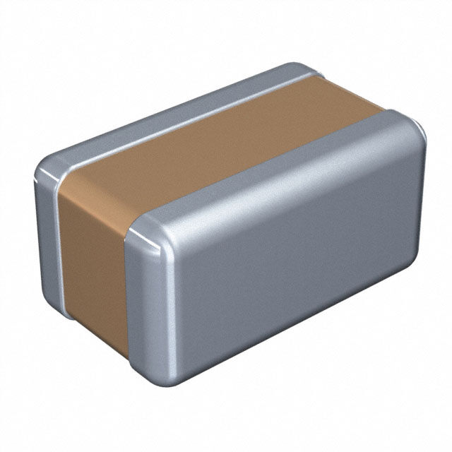
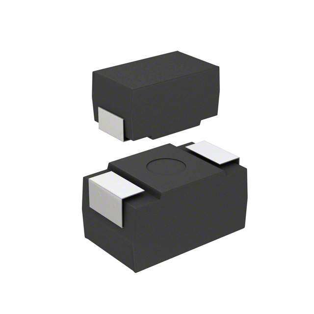
| 描述 | CAP CER 0.47UF 6.3V 10% X7R 0508多层陶瓷电容器MLCC - SMD/SMT 6.3V 0.47uF X7R 10% Flip chip 0508 |
| 产品分类 | |
| 品牌 | TDK |
| 产品手册 | |
| 产品图片 |
|
| rohs | 符合RoHS无铅 / 符合限制有害物质指令(RoHS)规范要求 |
| 产品系列 | MLCC,多层陶瓷电容器MLCC - SMD/SMT,TDK C1220X7R0J474KC |
| 数据手册 | |
| 产品型号 | C1220X7R0J474K |
| 产品 | Reverse Geometry Type MLCCs |
| 产品目录绘图 |
|
| 产品目录页面 | |
| 产品种类 | 多层陶瓷电容器MLCC - SMD/SMT |
| 其它名称 | 445-4071-1 |
| 包装 | 剪切带 (CT) |
| 厚度(最大值) | 0.039"(1.00mm) |
| 商标 | TDK |
| 外壳代码-in | 0508 (Reversed) |
| 外壳代码-mm | 1220 (Reversed) |
| 大小/尺寸 | 0.049" 长 x 0.079" 宽(1.25mm x 2.00mm) |
| 安装类型 | 表面贴装,MLCC |
| 容差 | 10 % |
| 封装 | Reel |
| 封装/外壳 | 0508(1220 公制) |
| 封装/箱体 | 0508 (Reversed) |
| 工作温度 | -55°C ~ 125°C |
| 工厂包装数量 | 4000 |
| 应用 | 旁通,去耦 |
| 引线形式 | - |
| 引线间距 | - |
| 最大工作温度 | + 125 C |
| 最小工作温度 | - 55 C |
| 标准包装 | 1 |
| 温度系数 | X7R |
| 温度系数/代码 | +/- 15 % |
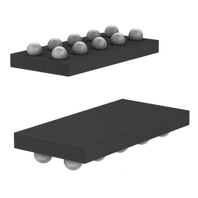
| 特性 | 低 ESL 型(倒置结构) |
| 特色产品 | http://www.digikey.cn/product-highlights/cn/zh/tdk-c-series-reverse-geometry-mlcc/2510 |
| 电介质 | X7R |
| 电压-额定 | 6.3V |
| 电压额定值 | 6.3 V |
| 电压额定值DC | 6.3 V |
| 电容 | 0.47 uF |
| 端接类型 | SMD/SMT |
| 等级 | - |
| 类型 | Low ESL Reverse Geometery |
| 视频文件 | http://www.digikey.cn/classic/video.aspx?PlayerID=1364138032001&width=640&height=505&videoID=3113360146001 |
| 高度-安装(最大值) | - |

%20W.jpg)
.jpg)


- 商务部:美国ITC正式对集成电路等产品启动337调查
- 曝三星4nm工艺存在良率问题 高通将骁龙8 Gen1或转产台积电
- 太阳诱电将投资9.5亿元在常州建新厂生产MLCC 预计2023年完工
- 英特尔发布欧洲新工厂建设计划 深化IDM 2.0 战略
- 台积电先进制程称霸业界 有大客户加持明年业绩稳了
- 达到5530亿美元!SIA预计今年全球半导体销售额将创下新高
- 英特尔拟将自动驾驶子公司Mobileye上市 估值或超500亿美元
- 三星加码芯片和SET,合并消费电子和移动部门,撤换高东真等 CEO
- 三星电子宣布重大人事变动 还合并消费电子和移动部门
- 海关总署:前11个月进口集成电路产品价值2.52万亿元 增长14.8%


PDF Datasheet 数据手册内容提取
C Series Low ESL Flip Type Type: C0510 [EIA CC0204] C0816 [EIA CC0306] C1220 [EIA CC0508] C1632 [EIA CC0612] Issue date: April 2011 TDK MLCC US Catalog Version B11
REMINDERS Please read before using this product SAFETY REMINDERS REMINDERS 1. If you intend to use a product listed in this catalog for a purpose that may cause loss of life or other damage,youmustcontactourcompany’ssaleswindow. 2. We may modify products or discontinue production of a product listed in this catalog without prior notification. 3. We provide “Delivery Specification” that explain precautions for the specifications and safety of each product listed in this catalog. We strongly recommend that you exchange these delivery specifications withcustomersthatuseoneoftheseproducts. 4. Ifyouplantoexportaproductlistedinthiscatalog,keepinmindthatitmaybearestricteditemaccording tothe“ForeignExchangeandForeignTradeControlLaw”.Insuchcases,itisnecessarytoacquireexport permissioninharmonywiththislaw. 5. Any reproduction or transferring of the contents of this catalog is prohibited without prior permission from ourcompany. 6. We are not responsible for problems that occur related to the intellectual property rights or other rights of our company or a third party when you use a product listed in this catalog. We do not grant license of theserights. 7. This catalog only applies to products purchased through our company or one of our company’s official agencies.Thiscatalogdoesnotapplytoproductsthatarepurchasedthroughotherthirdparties. TDK MLCC US Catalog P a g e 1 9 6 Version B11
C Series Low ESL Flip Type Type: C0510, C0816, C1220, C1632 Features • Positioning the electrodes along the length of the Applications • Decoupling CPU power line chip device, reduces ESR and ESL components over • Bias line in CPU conventional products. • High speed digital IC/decoupling • Provides high frequency noise suppression effect • PC, cell phones, camcorders, etc. because the resonating frequency is high. • Flipped geometry provides low inductance (less than 400 pH). • Provides stabilization of power line voltage. Shape & • Suitable for IC decoupling application. Dimensions PC Board Pattern Case Dimensions (mm) Size a b c C0510 0.2 0.6 1.0 C0816 0.3 1.0 1.6 L Body Length C1220 0.5 1.6 2.0 W Body Width C1632 0.75 2.2 3.2 T Body Height B Terminal Width Dimensions in mm Part Number Construction C 1632 X5R 0J 106 M T XXXX Series Name Internal Codes Dimensions L x W (mm) Packaging Style Case Code Length Width Packaging Code Style C0510 0.52 ±0.05 1.00 ±0.05 T Tape & Reel C0816 (C<1µF) 0.80 ±0.10 1.60 ±0.10 Capacitance Tolerance C0816 (C≥1µF) 0.80 ±0.15 1.60 ±0.20 Tolerance Code Tolerance C1220 1.25 ±0.20 2.00 ±0.20 C1608 1.60 ±0.20 3.20 ±0.20 K ±15% M ±20% Temperature Characteristic Nominal Capacitance (pF) Temperature Capacitance Temperature The capacitance is expressed in three Characteristics Change Range digit codes and in units of picoFarads X5R ±15% -55 to +85ºC (pF). The first and second digits X6S ±22% -55 to +105ºC identify the first and second significant X7R ±15% -55 to +125ºC X7S ±22% -55 to +125ºC figures of the capacitance. The third digit identifies the multiplier. R Rated Voltage (DC) designates a decimal point. Voltage Code Voltage (DC) Capacitance Code Capacitance 0G 4V 0R5 0.5pF 0J 6.3V 010 1pF 1A 10V 102 1,000pF (1nF) 1C 16V 105 1,000,000pF (1µF) 1E 25V 1H 50V TDK MLCC US Catalog P a g e 1 9 7 Version B11
Capacitance C0510 [EIA CC0204] Range Chart Capacitance Range Chart Temperature Characteristics: X6S (±22%) Rated Voltage: 4V (0G) X6S Capacitance Cap Tolerance 0G (pF) Code (4V) 10,000 103 M: ± 20% 22,000 223 47,000 473 100,000 104 220,000 224 470,000 474 Standard Thickness 1,000,000 105 2,200,000 225 0.30 mm Capacitance C0510 [EIA CC0204] Range Table Class 2 (Temperature Stable) Temperature Characteristics X6S (-55 to +105ºC, ±22%) TDK Part Number Temperature Rated Capacitance Capacitance Thickness (Ordering Code) Characteristics Voltage (pF) Tolerance (mm) C0510X6S0G104M X6S 4V 100,000 ±20% 0.30 ±0.05 C0510X6S0G224M X6S 4V 220,000 ±20% 0.30 ±0.05 C0510X6S0G474M X6S 4V 470,000 ±20% 0.30 ±0.05 TDK MLCC US Catalog P a g e 1 9 8 Version B11
Capacitance C0816 [EIA CC0306] Range Chart Capacitance Range Chart Temperature Characteristics: X7R, (±15%), X7S (±22%), X5R (±15%), X6S (±22%) Rated Voltage: 16V (1C), 10V (1A), 6.3V (0J), 4V (0G) X7R X7S X5R X6S Capacitance Cap Tolerance 1C 0J 0G 1A 0J 0G (pF) Code (16V) (6.3V) (4V) (10V) (6.3V) (4V) 10,000 103 K: ± 10% 22,000 223 M: ± 20% 47,000 473 100,000 104 220,000 224 470,000 474 Standard Thickness 1,000,000 105 2,200,000 225 0.50 mm Capacitance C0816 [EIA CC0306] Range Table Class 2 (Temperature Stable) Temperature Characteristics X7R (-55 to +125ºC, ±15%), X7S (-55 to +125ºC, ±2%), X5R (-55 to +85ºC, ±15%) TDK Part Number Temperature Rated Capacitance Capacitance Thickness (Ordering Code) Characteristics Voltage (pF) Tolerance (mm) C0816X7R1C103K X7R 16V 10,000 ±10% 0.50 ±0.10 C0816X7R1C223K X7R 16V 22,000 ±10% 0.50 ±0.10 C0816X7R1C473K X7R 16V 47,000 ±10% 0.50 ±0.10 C0816X7R1C104K X7R 16V 100,000 ±10% 0.50 ±0.10 C0816X7R0J224K X7R 6.3V 220,000 ±10% 0.50 ±0.10 C0816X7S0G474K X7S 4V 470,000 ±10% 0.50 ±0.10 C0816X7S0G105M X7S 4V 1,000,000 ±20% 0.50 ±0.10 C0816X7S0G225M X7S 4V 2,200,000 ±20% 0.50 ±0.10 C0816X5R1A224K X5R 10V 220,000 ±10% 0.50 ±0.10 C0816X5R1A474K X5R 10V 470,000 ±10% 0.50 ±0.10 C0816X5R0J474K X5R 6.3V 470,000 ±10% 0.50 ±0.10 C0816X5R0J105M X5R 6.3V 1,000,000 ±20% 0.50 ±0.10 C0816X5R0J225M X5R 6.3V 2,200,000 ±20% 0.50 ±0.10 TDK MLCC US Catalog P a g e 1 9 9 Version B11
Capacitance C1220 [EIA CC0508] Range Chart Capacitance Range Chart Temperature Characteristics: X7R, (±15%), X5R (±15%) Rated Voltage: 50V (1H), 25V (1E), 16V (1C), 10V (1A), 6.3V (0J) X7R X5R Capacitance Cap Tolerance 1H 1E 1C 0J 1A (pF) Code (50V) (25V) (16V) (6.3V) (10V) 10,000 103 K: ± 10% 22,000 223 M: ± 20% 47,000 473 100,000 104 220,000 224 Standard Thickness 470,000 474 1,000,000 105 0.85 mm Capacitance C1220 [EIA CC0508] Range Table Class 2 (Temperature Stable) Temperature Characteristics X7R (-55 to +125ºC, ±15%), X5R (-55 to +85ºC, ±15%) TDK Part Number Temperature Rated Capacitance Capacitance Thickness (Ordering Code) Characteristics Voltage (pF) Tolerance (mm) C1220X7R1H103K X7R 50V 10,000 ±10% 0.85 ±0.10 C1220X7R1H223K X7R 50V 22,000 ±10% 0.85 ±0.10 C1220X7R1H473K X7R 50V 47,000 ±10% 0.85 ±0.10 C1220X7R1E104K X7R 25V 100,000 ±10% 0.85 ±0.10 C1220X7R1C224K X7R 16V 220,000 ±10% 0.85 ±0.10 C1220X7R0J474K X7R 6.3V 470,000 ±10% 0.85 ±0.10 C1220X7R0J105M X7R 6.3V 1,000,000 ±20% 0.85 ±0.10 C1220X5R1A474K X5R 10V 470,000 ±10% 0.85 ±0.10 C1220X5R1A105M X5R 10V 1,000,000 ±20% 0.85 ±0.10 TDK MLCC US Catalog P a g e 2 0 0 Version B11
Capacitance C1632 [EIA CC0612] Range Chart Capacitance Range Chart Temperature Characteristics: X7R, (±15%), X7S (±22%), X5R (±15%) Rated Voltage: 50V (1H), 25V (1E), 16V (1C), 10V (1A), 6.3 (0J), 4V (0G) X7R X7S X5R Capacitance Cap Tolerance 1H 1E 1C 0J 0G 1A 0J (pF) Code (50V) (25V) (16V) (6.3V) (4V) (10V) (6.3V) 10,000 103 K: ± 10% 22,000 223 M: ± 20% 47,000 473 100,000 104 220,000 224 470,000 474 1,000,000 105 2,200,000 225 4,700,000 475 10,000,000 106 Standard Thickness 0.70 mm 1.15 mm 1.30 mm TDK MLCC US Catalog P a g e 2 0 1 Version B11
Capacitance C1632 [EIA CC0612] Range Table Class 2 (Temperature Stable) Temperature Characteristics X7R (-55 to +125ºC, ±15%), X7S (-55 to +125ºC, ±2%), X5R (-55 to +85ºC, ±15%) TDK Part Number Temperature Rated Capacitance Capacitance Thickness (Ordering Code) Characteristics Voltage (pF) Tolerance (mm) C1632X7R1H103K X7R 50V 10,000 ±10% 0.70 ±0.10 C1632X7R1H223K X7R 50V 22,000 ±10% 0.70 ±0.10 C1632X7R1H473K X7R 50V 47,000 ±10% 0.70 ±0.10 C1632X7R1H104K X7R 50V 100,000 ±10% 0.70 ±0.10 C1632X7R1H224K X7R 50V 220,000 ±10% 1.15 ±0.10 C1632X7R1E224K X7R 25V 220,000 ±10% 0.70 ±0.10 C1632X7R1E474K X7R 25V 470,000 ±10% 1.15 ±0.10 C1632X7R1C474K X7R 16V 470,000 ±10% 0.70 ±0.10 C1632X7R1C105K X7R 16V 1,000,000 ±10% 1.15 ±0.10 C1632X7R0J105M X7R 6.3V 1,000,000 ±20% 0.70 ±0.10 C1632X7R0J225M X7R 6.3V 2,200,000 ±20% 1.15 ±0.10 C1632X7S0G475M X7S 4V 4,700,000 ±20% 1.30 ±0.10 C1632X7S0G106M X7S 4V 10,000,000 ±20% 1.30 ±0.10 C1632X5R1A105M X5R 10V 1,000,000 ±20% 0.70 ±0.10 C1632X5R1A225M X5R 10V 2,200,000 ±20% 1.15 ±0.10 C1632X5R0J475M X5R 6.3V 4,700,000 ±20% 1.30 ±0.10 C1632X5R0J106M X5R 6.3V 10,000,000 ±20% 1.30 ±0.10 TDK MLCC US Catalog P a g e 2 0 2 Version B11
General C Series – Low ESL Flip Type Specifications No. Item Performance Test or Inspection Method 1 External No defects which may affect Inspect with magnifying glass (3×). Appearance performance. 2 Insulation 10,000MΩor 500MΩ•μF min. Apply rated voltage for 60s. Resistance (whichever smaller). As for the capacitor of rated voltage 16, 10, 6.3 and 4V DC, 100MΩ•μF min. 3 Voltage Proof Withstand test voltage without Apply 2.5 x rated voltage for 1 ~ 5s. insulation breakdown or other damage. Charge / discharge current shall not exceed 50mA. 4 Capacitance Within the specified tolerance. Measuring Rated Measuring Frequency Voltage Voltage 50V ~ 6.3V 1.0±0.2 V 1kHz±10% rms 4V 0.5 -5 V rms 5 Dissipation T.C. Rated Voltage D.F. See No.4 in this table for measuring condition. Factor X7R 50V, 25V DC 0.03 max. (Class 2) X7R 16V, 10V, 6.3V 0.05 max. X5R DC X7S X6S 4V DC 0.12 max. X5S 6 Temperature Capacitance Change (%) Capacitance shall be measured by the steps shown in Characteristics No Voltage Applied the following table after thermal equilibrium is obtained of Capacitance T.C. ΔC Percent for each step. (Class 2) X5R ∆C be calculated ref. STEP3 reading ±15% X7R Step Temperature (ºC) X5S 1 Reference temp. ±2 X6S ±22% 2 Min. operating temp. ±2 X7S 3 Reference temp. ±2 4 Max. operating temp. ±2 7 Robustness of No sign of termination coming off, Reflow solder the capacitor on P.C. board (shown in Terminations breakage of ceramic, or other abnormal Appendix 1) and apply a pushing force of 5N (C0510: signs. 2N) for 10 ±1s. 5N (2N for C0510) P.C.Board Capacitors TDK MLCC US Catalog P a g e 2 0 3 Version B11
General C Series – Low ESL Flip Type Specifications No. Item Performance Test or Inspection Method 8 Bending No mechanical damage. Reflow solder the capacitor on P.C. board (shown in Appendix 2) and bend it for 1mm. 20 50 F R230 1 45 45 Unit: mm 9 Solderability New solder to cover over 75% of Completely soak both terminations in solder at 235 ± termination. 5ºC for 2 ±0.5s. 25% may have pinholes or rough spots Solder: but not concentrated in one spot. H63A (JIS Z 3282) Ceramic surface of “A sections” shall Flux: not be exposed due to melting or Isopropyl alcohol (JIS K 8839) shifting of termination material. Rosin (JIS K 5902) 25% solid solution. A section 10 Resistance to solder heat Completely soak both terminations in solder at 260 ± 5ºC for 5 ±1s. External No cracks are allowed and terminations appearance shall be covered at least 60% with new Preheating condition solder. Temp. : 150 ±10ºC Time: 1 ~ 2min. Capacitance Change from the Characteristics value before test Flux: X7R Isopropyl alcohol (JIS K 8839) X7S Class 2 ±7.5 % Rosin (JIS K 5902) 25% solid solution. X5R X6S Solder : H63A (JIS Z 3282) D.F. (Class 2) Meet the initial spec. Leave the capacitor in ambient conditions for 24 ±2h before measurement. Insulation Meet the initial spec. Resistance Voltage proof No insulation breakdown or other damage. TDK MLCC US Catalog P a g e 2 0 4 Version B11
General C Series – Low ESL Flip Type Specifications No. Item Performance Test or Inspection Method 11 Vibration Solder the capacitors on P.C. board (shown in Appendix 1) before testing. External No mechanical damage. appearance Vibrate the capacitor with amplitude of 1.5mm P-P changing the frequencies from 10Hz to 55Hz and back Capacitance Change from the to 10Hz in about 1min. Characteristics value before test Repeat this for 2h each in 3 perpendicular directions. X7R X7S Class 2 ±7.5 % X5R X6S D.F. (Class 2) Meet the initial spec. 12 Temperature cycle Solder the capacitors on P.C. board (shown in Appendix 1) before testing. External No mechanical damage. appearance Expose the capacitor in the conditions step1 through 4 and repeat 5 times consecutively. Capacitance Change from the Characteristics Leave the capacitor in ambient conditions for 24 ±2h value before test before measurement. X7R Class 2 X7S ±7.5 % Step Temperature (ºC) Time (min.) X5R 1 Min. operating temp. ±3 30 ±3 X6S 2 Reference Temp. 2 –5 3 Max. operating temp. ±2 30 ±2 D.F. (Class 2) Meet the initial spec. 4 Reference Temp. 2 -5 Insulation 1,000MΩor 50MΩ•μF min. whichever Resistance smaller. Voltage Proof No insulation breakdown or other damage. 13 Moisture Resistance (Steady State) Solder the capacitor on P.C. board (shown in Appendix 1) before testing. External No mechanical damage. appearance Leave at temperature 40 ±2ºC, 90 to 95%RH for 500 +24, 0h. Capacitance Change from the Characteristics Leave the capacitor in ambient conditions for 24 ±2h value before test before measurement. X7R X7S Class 2 ±12.5 % X5R X6S D.F. (Class 2) Characteristics X7R: 200% of initial spec. max. X7S: 200% of initial spec. max. X5R: 200% of initial spec. max. X6S: 200% of initial spec. max. Insulation 1,000MΩor 50MΩ•μF min. (whichever Resistance smaller). As for the capacitor of rated voltage 16, 10, 6.3 and 4V DC, 10MΩ•μF min. TDK MLCC US Catalog P a g e 2 0 5 Version B11
General C Series – Low ESL Flip Type Specifications No. Item Performance Test or Inspection Method 14 Moisture Resistance Solder the capacitors on P.C. board (shown in Appendix 1) before testing. External No mechanical damage. appearance Apply the rated voltage at temperature 40 ±2ºC and 90 to 95%RH for 500 +24, 0h. Capacitance Change from the Characteristics Charge/discharge current shall not exceed 50mA. value before test X7R Leave the capacitor in ambient conditions for 48 ±4h X7S before measurement. Class 2 ±12.5 % X5R Voltage conditioning: X6S Voltage treats the capacitor under testing temperature D.F. (Class 2) Characteristics and voltage for 1hour. X7R: 200% of initial spec. max. Leave the capacitor in ambient conditions for 24 ±2h X7S: 200% of initial spec. max. before measurement. X5R: 200% of initial spec. max. Use this measurement for initial value. X6S: 200% of initial spec. max. Insulation 500MΩor 25MΩ•μF min. (whichever Resistance smaller). As for the capacitor of rated voltage 16, 10, 6.3 and 4V DC, 5MΩ•μF min. 15 Life Reflow Solder the capacitor on P.C. board (shown in Appendix 1) before testing. External No mechanical damage. appearance Apply rated voltage at maximum operating temperature ±2ºC for 1,000 +48, 0h. Capacitance Change from the Characteristics value before test Charge/discharge current shall not exceed 50mA. X7R Leave the capacitor in ambient conditions for 24 ±2h X7S Class 2 ±15 % before measurement. X5R X6S Voltage conditioning: Voltage treats the capacitor under testing temperature D.F. (Class 2) Characteristics and voltage for 1hour. X7R: 200% of initial spec. max. Leave the capacitor in ambient conditions for 48 ±4h X7S: 200% of initial spec. max. before measurement. X5R: 200% of initial spec. max. X6S: 200% of initial spec. max. Use this measurement for initial value. Insulation 1,000MΩor 50MΩ•μF min. whichever Resistance smaller. As for the capacitor of rated voltage 16, 10, 6.3 and 4V DC, 10MΩ•μF min. *As for the initial measurement of capacitors on number 6, 10, 11, 12 and 13, leave capacitor at 150 -10, 0°C for 1h and measure the value after leaving capacitor for 24 ±2h in ambient condition. TDK MLCC US Catalog P a g e 2 0 6 Version B11
General C Series – Low ESL Flip Type Specifications Appendix -1 Appendix -2 P.C. Board for reliability test P.C. Board for bending test 100 mm 100 mm c b m a m b a mm 1.0 c mm 0 0 4 4 Solder Resist Copper Solder Resist Copper Material : Glass Epoxy ( As per JIS C6484 GE4 ) Case Code Dimensions (mm) JIS EIA a b c P.C. Board thickness : Appendix 1,2 1.6mm C0510 CC0204 0.2 0.6 1.0 C0816 CC0306 0.3 1.0 1.6 Copper ( thickness 0.035mm ) C1220 CC0508 0.5 1.6 2.0 Solder resist C1632 CC0612 0.75 2.2 3.2 TDK MLCC US Catalog P a g e 2 0 7 Version B11
Soldering C Series – Low ESL Flip Type Information • Recommended Soldering Land Pattern • Recommended Soldering Profile Chip capacitor Reflow Soldering Manual soldering Solder land Preheating SolderingNcoaotulinragl (Solder iron) Peak 300 Solder resist Temp C) C) C mp (º ∆T mp (º ∆T Te Te 0 0 Preheating B A Over 60 sec. Peak Temp time 3sec. (As short as possible) Reflow Soldering Unit: mm Recommended soldering duration Type C0510 C0816 C1220 C1632 Symbol [CC0204] [CC0306] [CC0508] [CC0612] Temp./ Reflow Soldering A 0.20 0.30 0.50 0.75 Dura. Peak temp Duration B 0.20 0.35 0.55 0.725 Solder (°C) (sec.) C 1.00 1.60 2.00 3.20 Sn-Pb Solder 230 max. 20 max. Lead-Free Solder 260 max. 10 max. • Recommended Solder Amount Recommended solder compositions Sn-37Pb (Sn-Pb solder) Higher tensile Sn-3.0Ag-0.5Cu (Lead Free Solder) Excessive force on the chip solder capacitor may Preheating Condition cause cracking. Soldering Temp. (ºC) Reflow soldering ∆T ≤ 150 Maximum amount Adequate Minimum amount Manual soldering ∆T ≤ 150 solder Small solder fillet may cause Insufficient contact failure or solder failure to hold the chip capacitor to the P.C. board. TDK MLCC US Catalog P a g e 2 0 8 Version B11
Packaging C Series – Low ESL Flip Type Information • Carrier Tape Configuration Bulk Chips Bulk 160mm min. 160mm min Drawing direction Leader 400mm min • Peel Back Force (Top Tape) Direction & angle of pull • Carrier tape shall be flexible enough to be Top cover tape wound around a minimum radius of 30mm with Carrier tape 0.05 –0.7 N components in tape. • The missing of components shall be less than 0.1% 0~15° • Components shall not stick to the cover tape. • The cover tape shall not protrude beyond the edges of the carrier tape not shall cover the sprocket holes. Direction of pull force Bottom cover tape (Paper carrier tape of type 2) • Chip Quantity Per Reel and Structure of Reel (Paper & Plastic) Paper Carrier Tape & Reel (Type 1) Paper Carrier Tape & Reel (Type 2) Top cover tape Top cover tape Pitch hole Pitch hole Cavity (Press formed type) Cavity (Chip insert) Paper Carrier Tape & Reel (Type 3) Top cover tape Plastic carrier tape Paper carrier tape Pitch hole Cavity (Chip insert) Paper carrier tape Bottom cover tape Case Code Chip Chip quantity (pcs.) Taping Material JIS EIA Thickness φ178mm (7”) reel φ330mm (13”) reel C0510 CC0204 0.50 mm Paper (Type 1) 15,000 50,000 C0816 CC0306 0.80 mm Plastic (Type 3) 4,000 10,000 C1220 CC0508 0.85 mm Paper (Type 2) 4,000 10,000 0.70 mm 4,000 C1632 CC0612 1.15 mm Plastic (Type 3) 10,000 2,000 1.30 mm TDK MLCC US Catalog P a g e 2 0 9 Version B11
Additional C Series – Low ESL Flip Type Information • Shape & Dimensions • Environmental Information Terminal electrode TDK Corporation established internal product environmental L assurance standards that include the six hazardous B substances banned by the EU RoHSDirective1enforced on W B July 1, 2006 along with additional substances independently banned by TDK and has successfully completed making T general purpose electronic components conform to the RoHSDirective2. 1. Abbreviation for Restriction on Hazardous Substances, which refers to the regulation EU Directive 2002/95/EC on hazardous substances by the European Union (EU) effective from July 1, 2006. Internal electrode The Directive bans the use of six specific hazardous Ceramic dielectric substances in electric and electronic devices and products handled within the EU. The six substances Case Code Dimensions (mm) are lead, mercury, cadmium, hexavalentchromium, JIS EIA L W T B G PBB (polybrominatedbiphenyls), and PBDE (polybrominateddiphenylethers). C0510 CC0204 0.52 1.00 0.50 0.10 min. 0.09 min. C0816 CC0306 0.80 1.60 0.80 0.10 min. - 2. This means that, in conformity with the EU Directive C1220 CC0508 1.25 2.00 0.85 0.20 min. 0.40 min. 2002/95/EC, lead, cadmium, mercury, hexavalent 0.70 chromium, and specific bromine-based flame C1632 CC0612 1.60 3.20 1.15 0.20 min. 0.50 min. retardants, PBB and PBDE, have not been used, 1.30 except for exempted applications. For REACH (SVHC : 15 substances according to ECHA / October 2008) : All TDK MLCC do not contain these • Inside Structure & Material System 15 substances. For European Directive 2000/53/CE and 2005/673/CE : Cadmium, HexavalentChromium, Mercury, Lead are 3 not contained in all TDK MLCC. 4 For European Directive 2003/11/CE : Pentabromodiphenyl- 5 ether, Octabromodiphenyl-ether are not contained in all TDK MLCC. 1 2 No. NAME MATERIAL Class 2 (1) Ceramic Dielectric BaTiO 3 (2) Internal Electrode Nickel (Ni) (3) Copper (Cu) (4) Termination Nickel (Ni) (5) Tin (Sn) TDK MLCC US Catalog P a g e 2 1 0 Version B11