ICGOO在线商城 > 开发板,套件,编程器 > 评估和演示板和套件 > BQ20Z65EVM
 Datasheet下载
- 型号: BQ20Z65EVM
- 制造商: Texas Instruments
- 库位|库存: xxxx|xxxx
- 要求:
| 数量阶梯 | 香港交货 | 国内含税 |
| +xxxx | $xxxx | ¥xxxx |
查看当月历史价格
查看今年历史价格
BQ20Z65EVM产品简介:
ICGOO电子元器件商城为您提供BQ20Z65EVM由Texas Instruments设计生产,在icgoo商城现货销售,并且可以通过原厂、代理商等渠道进行代购。 BQ20Z65EVM价格参考。Texas InstrumentsBQ20Z65EVM封装/规格:评估和演示板和套件, BQ20Z65, BQ29330, BQ29412 Battery Gauge Power Management Evaluation Board。您可以下载BQ20Z65EVM参考资料、Datasheet数据手册功能说明书,资料中有BQ20Z65EVM 详细功能的应用电路图电压和使用方法及教程。
Texas Instruments(德州仪器)的BQ20Z65EVM是一款评估模块,主要用于评估BQ20Z65电池管理集成电路的性能和功能。该评估板属于“评估和演示板及套件”类别,适用于以下应用场景:

1. 锂离子/锂聚合物电池组开发:BQ20Z65EVM支持对锂离子和锂聚合物电池组进行充放电管理和监控,帮助工程师设计高效、安全的电池管理系统。

2. 电量计功能测试:该模块能够评估BQ20Z65的电量计功能,包括剩余容量、状态-of-charge(SOC)、电池健康状态(SOH)等参数的精确测量。

3. 通信接口测试:BQ20Z65EVM支持多种通信协议(如I2C、SMBus),允许用户测试与主机系统之间的数据交互能力,确保电池信息能够准确传递到设备主控芯片。

4. 保护功能验证:通过该评估板,可以验证过压、欠压、过流、过温等保护机制是否正常工作,以确保电池组在各种极端条件下的安全性。

5. 充电算法优化:工程师可以利用此评估板测试不同的充电算法,调整充电曲线以适应特定应用需求,提高充电效率并延长电池寿命。

6. 便携式电子产品设计:适用于笔记本电脑、平板电脑、电动工具和其他需要可充电电池组的便携式电子产品的研发阶段,帮助设计师快速搭建原型并验证方案可行性。

7. 工业与医疗设备应用:在需要高精度电池管理的工业设备或医疗仪器中,BQ20Z65EVM可用于开发可靠的电池解决方案。

总结来说,BQ20Z65EVM为工程师提供了一个全面的平台,用于评估和优化基于BQ20Z65芯片的电池管理系统,从而加速产品开发周期并提升最终产品的性能和安全性。
| 参数 | 数值 |
| 产品目录 | 编程器,开发系统半导体 |
| 描述 | EVAL MODULE FOR BQ20Z65电源管理IC开发工具 Batt Mgmt Solution Eval Mod |
| 产品分类 | |
| 品牌 | Texas Instruments |
| 产品手册 | |
| 产品图片 |
|
| rohs | 否无铅 / 符合限制有害物质指令(RoHS)规范要求 |
| 产品系列 | 电源管理IC开发工具,Texas Instruments BQ20Z65EVMImpedance Track™ |
| 数据手册 | 点击此处下载产品Datasheethttp://www.ti.com/lit/pdf/sluu353 |
| 产品型号 | BQ20Z65EVM |
| 主要属性 | 符合 SBS 1.1 标准的高级电量检测计 |
| 主要用途 | 电源管理,电池检测计 |
| 产品 | Evaluation Modules |
| 产品种类 | 电源管理IC开发工具 |
| 使用的IC/零件 | BQ20Z65,BQ29330,BQ29412 |
| 其它名称 | 296-30728 |
| 制造商产品页 | http://www.ti.com/general/docs/suppproductinfo.tsp?distId=10&orderablePartNumber=BQ20Z65EVM |
| 商标 | Texas Instruments |
| 尺寸 | 100 mm x 30 mm |
| 嵌入式 | 否 |
| 工具用于评估 | BQ20Z65 |
| 工厂包装数量 | 1 |
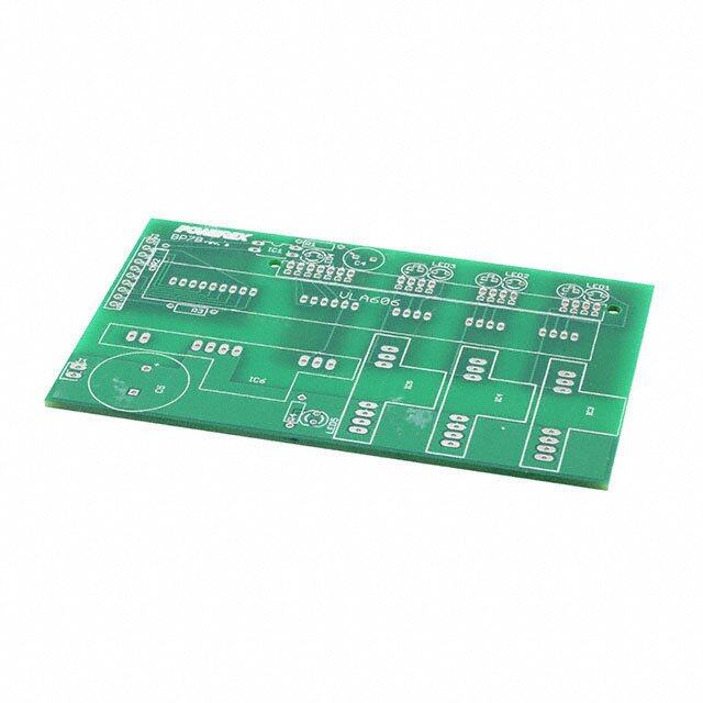
| 所含物品 | 板 |
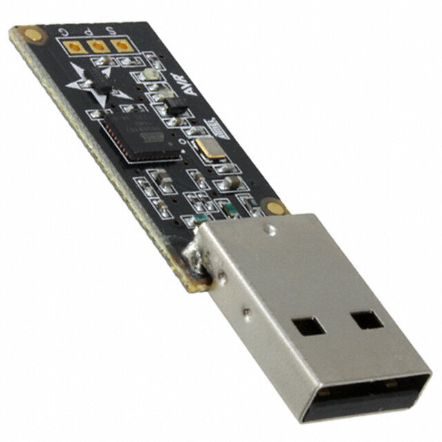
| 接口类型 | USB |
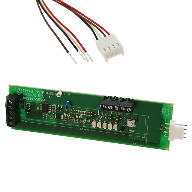
| 描述/功能 | The EVM includes one bq20z65 circuit module, a current sense resistor, two thermistors, and a link to Windows based PC software |
| 标准包装 | 1 |
| 类型 | Battery Management |
| 辅助属性 | 过度充电、过度放电、短路和过流保护 |
| 输入电压 | 6 V to 25 V |


- 商务部:美国ITC正式对集成电路等产品启动337调查
- 曝三星4nm工艺存在良率问题 高通将骁龙8 Gen1或转产台积电
- 太阳诱电将投资9.5亿元在常州建新厂生产MLCC 预计2023年完工
- 英特尔发布欧洲新工厂建设计划 深化IDM 2.0 战略
- 台积电先进制程称霸业界 有大客户加持明年业绩稳了
- 达到5530亿美元!SIA预计今年全球半导体销售额将创下新高
- 英特尔拟将自动驾驶子公司Mobileye上市 估值或超500亿美元
- 三星加码芯片和SET,合并消费电子和移动部门,撤换高东真等 CEO
- 三星电子宣布重大人事变动 还合并消费电子和移动部门
- 海关总署:前11个月进口集成电路产品价值2.52万亿元 增长14.8%

PDF Datasheet 数据手册内容提取
User's Guide SLUU353–June2009 bq20z65EVM-001 SBS 1.1 Impedance Track™ Technology Enabled Battery Management Solution Evaluation Module This evaluation module (EVM) is a complete evaluation system for the bq20z65/bq29412 battery management system. The EVM includes one bq20z65/bq29412 circuit module and a link to Windows™-based PC software. The circuit module includes one bq20z65 integrated circuit (IC), one bq29412 IC, and all other onboard components necessary to monitor and predict capacity, perform cell balancing, monitor critical parameters, protect the cells from overcharge, over-discharge, short-circuit, and overcurrentin2-,3-or4-seriescellLi-ionorLi-polymerbatterypacks.Thecircuit module connects directly across the cells in a battery. With the EV2300 interface board and software, the user can read the bq20z65 data registers, program the chipset for different pack configurations, log cycling data for further evaluation, and evaluate the overall functionality of the bq20z65/bq29412 solution under different charge anddischargeconditions. Contents 1 Features....................................................................................................................... 2 2 bq20z65-BasedCircuitModule............................................................................................ 2 3 bq20z65CircuitModuleSchematic....................................................................................... 3 4 CircuitModulePhysicalLayoutsandBillofMaterials.................................................................. 3 5 EVMHardwareandSoftwareSetup...................................................................................... 8 6 TroubleshootingUnexpectedDialogBoxes.............................................................................. 8 7 HardwareConnection....................................................................................................... 8 8 Operation..................................................................................................................... 9 9 CalibrationScreen.......................................................................................................... 12 10 Pro(Advanced)Screen.................................................................................................... 13 11 RelatedDocumentationfromTexasInstruments...................................................................... 14 ListofFigures 1 bq20z65EVM-001Layout–SilkScreen.................................................................................. 4 2 TopAssembly................................................................................................................ 4 3 TopLayer..................................................................................................................... 4 4 BottomLayer................................................................................................................. 5 5 BottomAssembly............................................................................................................ 5 6 Schematic..................................................................................................................... 7 7 bq20z65CircuitModuleConnectiontoCellsandSystemLoad/Charger............................................ 9 8 SBSDataScreen........................................................................................................... 10 9 DataFlashScreen,1stLevelSafetyClass............................................................................. 11 10 CalibrationScreen.......................................................................................................... 13 11 Pro(Advanced)Screen.................................................................................................... 14 ListofTables 1 OrderingInformation ........................................................................................................ 2 2 ComponentsandFlash-MemorySettingsforDifferentPrechargeModes........................................... 3 3 BillofMaterials............................................................................................................... 5 4 PerformanceSpecificationSummary..................................................................................... 8 5 CircuitModuletoEV2300Connections................................................................................... 9 SLUU353–June2009 bq20z65EVM-001SBS1.1ImpedanceTrack™Technology 1 SubmitDocumentationFeedback EnabledBatteryManagementSolutionEvaluationModule
Features www.ti.com 1 Features • Complete evaluation system for the bq20z65 SBS 1.1-compliant advanced gas gauge with Impedance Track™technologyandbq29412independentovervoltageprotectionIC • Populatedcircuitmoduleforquicksetup • Softwarethatallowsdataloggingforsystemanalysis 1.1 Kit Contents • bq20z65/bq29412circuitmodule • Setofsupportdocumentation 1.2 Ordering Information Table1.OrderingInformation EVMPARTNUMBER CHEMISTRY CONFIGURATION CAPACITY bq20z65EVM-001 Li-ion 2,3,or4cell Any 2 bq20z65-Based Circuit Module Thebq20z65/bq29412-basedcircuitmoduleisacompleteandcompactexamplesolutionofabq20z65 circuitforbatterymanagementandprotectionofLi-ionorLi-polymerpacks.Thecircuitmodule incorporatesabq20z65batterymonitorIC,bq29412independentovervoltageprotectionIC,andallother componentsnecessarytoaccuratelypredictthecapacityof2-,3-,or4-seriescells. 2.1 Circuit Module Connections Contactsonthecircuitmoduleprovidethefollowingconnections: • Directconnectiontothecells:1N(BAT-),1P,2P,3P,4P(BAT+) • Totheserialcommunicationsport(SMBC,SMBD) • ThesystemloadandchargerconnectacrossPACK+andPACK- • Tothesystem-presentpin(SYSPRES) 2.2 Pin Descriptions PINNAME DESCRIPTION 1N -veconnectionoffirst(bottom)cell 1P +veconnectionoffirst(bottom)cell 2P +veconnectionofsecondcell 3P +veconnectionofthirdcell 4P +veconnectionoffourth(top)cell SMBC Serialcommunicationportclock SMBD Serialcommunicationdataport SYSPRES Systempresentpin(iflow,systemispresent) PACK- Packnegativeterminal VSS Packnegativeterminal PACK+ Packpositiveterminal ImpedanceTrack,bqEasyaretrademarksofTexasInstruments. WindowsisatrademarkofMicrosoftCorporation. 2 bq20z65EVM-001SBS1.1ImpedanceTrack™Technology SLUU353–June2009 EnabledBatteryManagementSolutionEvaluationModule SubmitDocumentationFeedback
www.ti.com bq20z65CircuitModuleSchematic 3 bq20z65 Circuit Module Schematic Thissectioncontainsinformationformodifyingandchoosingaprechargemodeforbq20z65/bq29412 implementation. 3.1 Schematic Theschematicfollowsthebillofmaterialsinthisuser'sguide. 3.2 Modifications for Choosing Particular Precharge Mode Inordertocharge,thechargeFET(CHG-FET)mustbeturnedontocreateacurrentpath.Whenthe V is0VandCHG-FET=ON,theV isaslowasthebatteryvoltage.Inthiscase,thesupply (BAT) (PACK) voltageforthedeviceistoolowtooperate.Thisfunctionhasthreepossibleconfigurations,andtheICcan beeasilyconfiguredaccordingtotheapplicationneeds.Thethreemodesare0-VChargeFETmode, CommonFETmode,andPrechargeFETmode. 1. 0-VChargeFETmode-DedicatesaprechargecurrentpathusinganadditionalFET(ZVCHG-FET)to sustainthePACK+voltagelevel. 2. CommonFETmode-DoesnotuseadedicatedprechargeFET.ThechargeFET(CHG-FET)issetto ONstateasdefault. 3. PrechargeFETmode-Dedicatesaprechargecurrentpathusinganadditionalopen-drain(OD)pin driveFET(PCHG-FET)tosustainthePACK+voltagelevel. TouseaparticularmodeofchargingwiththeEVM,addorremovesomeelementsshowninTable2,and usethegivensettingsofDF.Configuration,ZVCHG1,0. Table2.ComponentsandFlash-MemorySettingsforDifferentPrecharge Modes MODE RESISTORS PRECHGFET ZVCHG1 ZVCHG0 1.0-VChg(default) R21,R28 Q3 0 0 2.CommonFET R24 Q2 0 1 3.Precharge R23,R28 Q3 1 0 Formoredetailsaboutprechargeoperationandmodechoices,seethebq20z65datasheet(SLUS878). 3.3 Testing Fuse-Blowing Circuit Topreventthelossofboardfunctionalityduringthefuse-blowingtest,theactualchemicalfuseisnot providedinthecircuit.FETQ1drivesTP3lowifafuse-blowconditionoccurs;so,monitoringTP3canbe usedtotestthiscondition.Fuseplacementontheapplicationboardisshowninthebq20z65datasheet reference-boardschematic. 4 Circuit Module Physical Layouts and Bill of Materials Thissectioncontainstheprinted-circuitboard(PCB)layout,billofmaterials,andassemblydrawingsfor thebq20z65/bq29412circuitmodule. SLUU353–June2009 bq20z65EVM-001SBS1.1ImpedanceTrack™Technology 3 SubmitDocumentationFeedback EnabledBatteryManagementSolutionEvaluationModule
CircuitModulePhysicalLayoutsandBillofMaterials www.ti.com 4.1 Board Layout Thissectionshowsthedimensions,PCBlayers(Figure1throughFigure5),andassemblydrawingforthe bq20z65module. Figure1.bq20z65EVM-001Layout–SilkScreen Figure2.TopAssembly Figure3.TopLayer 4 bq20z65EVM-001SBS1.1ImpedanceTrack™Technology SLUU353–June2009 EnabledBatteryManagementSolutionEvaluationModule SubmitDocumentationFeedback
www.ti.com CircuitModulePhysicalLayoutsandBillofMaterials Figure4.BottomLayer Figure5.BottomAssembly 4.2 Bill of Materials and Schematic Table3.BillofMaterials Count RefDes Description Size Mfr PartNumber 21 C1–C9,C12, Capacitor,Ceramic,0.1m F,50V,X7R,20% 0603 Any STD C13,C15–C18, C23,C24, C26–C28 1 C11 Capacitor,Ceramic,0.22m F,50V,X7R,20% 0603 Any STD 1 C19 Capacitor,Ceramic,4.7m F,10V,X7R,20% 0603 Any STD 1 C20 Capacitor,Ceramic,47nF,50V,X7R,20% 0603 Any STD 2 C22,C25 Capacitor,Ceramic,0.47m F,16V,X7R,20% 0603 Any STD 3 C10,C14,C21 Capacitor,Ceramic,1.0m F,25V,X7R,20% 0805 Any STD 4 D1–D3,D11 Diode,Switching,150-mA,75-V,350mW SOT23 Vishay-Liteon BAS16 2 D4,D5 Diode,Dual,Zener,5.6V,300mW SOT23 Vishay- AZ23C5V6 Telefunken 5 D6–D10 Diode,LED,Green,Gullwing,GWType,20ma,7.5 0.120· 0.087 Panasonic LN1361C mcdtyp. inches 1 J1 Header,FrictionLockAss'y,4-pinRightAngle, 0.400· 0.500 Molex 22-05-3041 1 Q1 MOSFET,N-ch,20-V,1.3A,0.16-W SOT23 Fairchild NDS331N 2 Q2,Q4 MOSFET,N-chLogicLevel,PowerTrench,30V,11A, SO8 Fairchild FDS6690A 12.5mW SLUU353–June2009 bq20z65EVM-001SBS1.1ImpedanceTrack™Technology 5 SubmitDocumentationFeedback EnabledBatteryManagementSolutionEvaluationModule
CircuitModulePhysicalLayoutsandBillofMaterials www.ti.com Table3.BillofMaterials (continued) Count RefDes Description Size Mfr PartNumber 1 Q3 MOSFET,P-ch,30-V,8.0-A,20-mW SO8 Siliconix Si4435DY 1 Q6 MOSFET,Nch,50V,0.22A,6W SOT23 Fairchild BSS138 12 R1–R5,R12, Resistor,Chip,100-W ,1/16-W,5% 0603 Std Std R13,R32–R34, R38,R39 1 R11 Resistor,Chip,0.010W ,1-W,xx% 2512 Vishay WSL-2512-0101% R86 3 R15,R16,R40 Resistor,Chip,220kW ,1/16-W,5% 0603 Std Std 1 R17 Resistor,Chip,300-W ,1-W,10% 2512 WSL-2512-3001% R86 2 R18,R27 Resistor,Chip,3.01MW ,1/16-W,5% 0603 Std Std 5 R14,R19, Resistor,Chip,5.1kW ,1/16-W,5% 0603 Std Std R21–R23 4 R20,R36,R37, Resistor,Chip,1MW ,1/16-W,5% 0603 Std Std R41 2 R24,R28 Resistor,Chip,100kW ,1/16-W,5% 0603 Std Std 2 R25,R29 Resistor,Chip,8.45kW ,1/16-W,1% 0603 Std Std 2 R26,R30 Resistor,Chip,61.9kW ,1/16-W,1% 0603 Std Std 7 R6–R10,R31, Resistor,Chip,1kW ,1/16-W,5% 0603 Std Std R35 2 RT1,RT2 Thermistor,10kW 0.095· 0.150 Semitec NTC103AT 1 SW1 Switch,Pushbutton,Momentary,N.O.LowProfile 5mm· 5mm Panasonic EVQPLCxxxx 2 TB1,TB4 TerminalBlock,2-pin,6-A,3,5mm 0.27· 0.25 OST ED1514 2 TB2,TB3 TerminalBlock,3-pin,6-A,3,5mm 0.41· 0.25 OST ED1515 1 TP1 TestPoint,Black,ThruHoleColorKeyed 0.100· 0.100inch Keystone 5001 1 TP3 TestPoint,White,ThruHoleColorKeyed 0.100· 0.100inch Keystone 5002 1 U1 IC,VoltageProtectionfor2,3,4CellLion,2nd SSOP-08 TI BQ29412DCT Protection,4.45VOVP 1 U2 IC,Cool-GGProgrammableBatteryManagement TSSOP30 TI bq20z65DBT 6 bq20z65EVM-001SBS1.1ImpedanceTrack™Technology SLUU353–June2009 EnabledBatteryManagementSolutionEvaluationModule SubmitDocumentationFeedback
www.ti.com CircuitModulePhysicalLayoutsandBillofMaterials Figure6.Schematic 4.3 bq20z65/bq29412 Circuit Module Performance Specification Summary Thissectionsummarizestheperformancespecificationsofthebq20z65/bq29412circuitmodule. SLUU353–June2009 bq20z65EVM-001SBS1.1ImpedanceTrack™Technology 7 SubmitDocumentationFeedback EnabledBatteryManagementSolutionEvaluationModule
EVMHardwareandSoftwareSetup www.ti.com Table4.PerformanceSpecificationSummary Specification Minimum Typical Maximum Units InputvoltagePack+toPack– 6 15 25 V Chargeanddischargecurrent 0 2 7 A 5 EVM Hardware and Software Setup Thissectiondescribeshowtoinstallthebq20z65PCsoftwareandhowtoconnectthedifferent componentsoftheEVM. 5.1 System Requirements Thebq20z65EVSWsoftwarerequiresWindows™2000orWindowsXP. 5.2 Software Installation Findthelatestsoftwareversioninthebq20z65toolfolderonpower.ti.com.Usethefollowingstepsto installthebq20z65EVSWsoftware: 1. CopythefilesfromtheTiWebsiteintoatemporarydirectoryyouselect,double-clickon bqEV-EASYSetup00.09.xx.exe,wherexxindicatestheversion,andfollowtheinstallerinstructionsto completethebq20z60EVSWinstallation. 2. IftheEV2300wasnotpreviouslyinstalled,afterbq20z60EVSWinstallation,aTIUSBDRIVER INSTALLERpopsup.ClickYesfortheagreementmessageandfollowitsinstructions.Twodriversare associatedwiththeEV2300.Followtheinstructionstoinstallboth.Donotrebootthecomputer,evenif askedtodoso. 3. PlugtheEV2300intoaUSBport.TheWindowssystemmayshowapromptthatnewhardwarehas beenfound.Whenasked,"CanWindowsconnecttoWindowsUpdatetosearchforsoftware?",select "No,notthistime"andclickonNEXT.Inthenextdialogwindow,itindicates"Thiswizardhelpsyou installsoftwarefor:TIUSBFirmwareUpdater",select"Installthesoftwareautomatically (Recommended)"andclickNEXT.ItiscommonforthenextscreentobetheConfirmFileReplace screen.ClickNotocontinue.Ifthisscreendoesnotappear,thengotothenextstep.AfterWindows indicatesthattheinstallationwasfinished,asimilardialogwindowpopsuptoinstalltheseconddriver; proceedwiththesameinstallationpreferenceasthefirstone.TheseconddriverisTIUSBbq80xx Driver. 6 Troubleshooting Unexpected Dialog Boxes Thefollowingactionscanhelptheusertoavoidunexpecteddialogboxes. • EnsurethatthefileswereextractedfromthezipfileusingthePreserveFoldernamesoption. • Ensurethatallthefileswereextractedfromthezipfile. • Theuserthatisdownloadingthefilesmustbeloggedinastheadministrator. • Thedriverisnotsigned,sotheadministratormustallowinstallationofunsigneddriversinthe operatingsystempolicy. 7 Hardware Connection Thebq20z65EVM-001comprisesthreehardwarecomponents:thebq20z65/bq29412circuitmodule,the EV2300PCinterfaceboard,andthePC. 7.1 Connecting bq20z65/bq29412 Circuit Module to Battery Pack Figure7showshowtoconnectthebq20z65/bq29412circuitmoduletothecellsandsystemload/charger. Thecellsmustbeconnectedinthefollowingorder: 8 bq20z65EVM-001SBS1.1ImpedanceTrack™Technology SLUU353–June2009 EnabledBatteryManagementSolutionEvaluationModule SubmitDocumentationFeedback
www.ti.com Operation 1. 4-CellPack:1N(BAT–),1P,2P,3P,and4P(seeSection2.1fordefinitions). 2. 3-CellPack:1N(BAT–),1P,2P,andthenconnect4Pand3Ptogether. 3. 2-CellPack:1N(BAT–),1P,andthenconnect4P,3P,and2Ptogether Tostartchargeordischargetest,connectPRESpintoPACK-pintosetSYSPRESstate.Totestsleep mode,disconnecttheSYSPRESpin. Figure7.bq20z65CircuitModuleConnectiontoCellsandSystemLoad/Charger 7.2 PC Interface Connection ThefollowingstepsconfigurethehardwareforinterfacetothePC: 1. Connectthebq20z65-basedsmartbatterytotheEV2300usingwireleadsasshowninTable5. Table5.CircuitModuletoEV2300Connections bq20z65-BasedBattery EV2300 SMBD SMBD SMBC SMBC VSS GND 2. ConnectthePCUSBcabletotheEV2300andthePCUSBport. Thebq20z65EVM-001isnowsetupforoperation. 8 Operation Thissectiondetailstheoperationofthebq20z65EVSWsoftware. 8.1 Starting the Program RunbqEvaluationSoftwarefromtheStart|Programs|TexasInstruments|bq20z65EVSWmenu sequence.TheSBSDatascreen(Figure8)appears.Databeginstoappearoncethe<Refresh>(single timescan)buttonisclicked,orwhenthe<KeepScanning>checkboxischecked.Todisablethescan feature,deselect<KeepScanning>. Thecontinuousscanningperiodcanbesetviathe|Options|and|SetScanInterval|menuselections. Therangeforthisintervalis0msto65535ms.Onlyitemsthatareselectedforscanningarescanned withinthisperiod. SLUU353–June2009 bq20z65EVM-001SBS1.1ImpedanceTrack™Technology 9 SubmitDocumentationFeedback EnabledBatteryManagementSolutionEvaluationModule
Operation www.ti.com ThebqEvaluationSoftwareprovidesaloggingfunctionwhichlogsthevaluesthatwerelastscannedby EVSW.Toenablethisfunction,selecttheStartLoggingbutton;thiscausestheKeepScanningbuttonto beselected.WhenloggingisStopped,thekeepscanningbuttonisstillselectedandhastobemanually unchecked. Theloggingintervalsarespecifiedunderthe|Options|menuwiththemaximumvalueof65535ms.The Logintervalcannotbesmallerthanthescanintervalbecausethisresultsinthesamevaluebeinglogged atleasttwice. Figure8.SBSDataScreen Thisscreen(Figure8)showstheSBSdatasetalongwithadditionalManufacturersAccess()command informationsuchasindividualcellmeasurements.AdditionalFlagandStaticdatacanbeviewedby selectingtheappropriatetabatthebottomoftheSBSscreen. DatasuchasSBS.ManufacturerName()isstaticanddoesnotchange.Thisdataisviewedseparately usingtheStaticDatatabavailableatthebottomofthescreen. Draggingthesplitterbar(linethatseparatestheFlags/StaticdatafromSBSvalues)changestheheightof theFlags/StaticDatadisplay.Selecting|View|,then|AutoArrange|returnsthesplitterbartoitsoriginal location. 10 bq20z65EVM-001SBS1.1ImpedanceTrack™Technology SLUU353–June2009 EnabledBatteryManagementSolutionEvaluationModule SubmitDocumentationFeedback
www.ti.com Operation 8.2 Setting Programmable bq20z65 Options Thebq20z65dataflashcomesconfiguredperthedefaultsettingsdetailedinthebq20z65datasheet. Ensurethatthesettingsarecorrectlychangedtomatchthepackandapplicationforthebq20z65solution beingevaluated. IMPORTANT:Thecorrectsettingoftheseoptionsisessentialtogetthebestperformance. ThesettingscanbeconfiguredusingtheDataFlashscreen(Figure9). Figure9.DataFlashScreen,1stLevelSafetyClass Toreadallthedatafromthebq20z65dataflash,clickonmenuoption|DataFlash|ReadAll|. Towritetoadataflashlocation,clickonthedesiredlocation,enterthedataandpress<Enter>,which writestheentiretabofflashdata,orselectmenuoption|DataFlash|WriteAll|.Thedataflashmustbe readbeforeanywritesareperformedtoavoidanyincorrectdatabeingwrittentothedevice. The|File|SpecialExport|menuoptionallowsthedataflashtobeexported,butitconfiguresthe exporteddataflashtoalearnedstatereadyformassproductionuse. Thedataflashconfigurationcanbesavedtoafilebyselecting|File|Export|andenteringafilename.A dataflashfilealsocanberetrievedinthisway,imported,andwrittentothebq20z65usingthe|WriteAll| button. Theconfigurationinformationofthebq29z95andmodulecalibrationdataalsoisheldinthebq20z65data flash. SLUU353–June2009 bq20z65EVM-001SBS1.1ImpedanceTrack™Technology 11 SubmitDocumentationFeedback EnabledBatteryManagementSolutionEvaluationModule
CalibrationScreen www.ti.com Thebq20z65allowsforanautomaticdataflashexportfunction,similartotheSBSDataloggingfunction. Thisfeature,whenselectedvia|Options|AutoExport|,exportsDataFlashtoasequentialseriesoffiles namedasFilenameNNNNN.ggwhereN=adecimalnumberfrom0to9. TheAutoExportintervalissetunderthe|Optionsmenu|withaminimumvalueof15s.TheAutoExport filenamealsoissetunderthe|Optionsmenu|. Whenacheckmarkisnextto|AutoExport|,theAutoExportisinprogress.Thesamemenuselectionis usedtoturnon/offAutoExport. Ifthedataflashscreenisblank,thenthebq20z65thatisbeingusedmaynotbesupportedbythe bqEVSWversionthatisbeingused.Anupgrademayberequired. 9 Calibration Screen 9.1 How to Calibrate Thebq20z65mustbecalibratedusingpowersuppliesorapowersupplyandcellsimulationresistors(200 W to1000W each)beforecellsareattached.Beforethebq20z65iscalibrated: • Connect and measure a 2-A current source from 1N (-) and Pack- (+) to calibrate without using the FETs.(CalibrationusingtheFETsisnotrecommended.) • MeasurethepackvoltagefromBatt+toBatt-(totalofcellvoltages). • Measurethetemperatureofthepack. • Thesestepsmaynotberequired,dependingonthetypeofcalibrationbeingperformed. 9.2 To Calibrate the bq20z65 Performthefollowingsteps. 1. Selectthetypesofcalibrationtobeperformed(seeFigure10). 2. Enterthemeasuredvaluesforthetypesselected(exceptforCCOffsetCalibration). 3. IfVoltageCalibrationisselected,thenenterthenumberofcellsonthepack. 4. IfTemperatureCalibrationisselected,thenselectthesensorthatistobecalibrated. 5. Ifthecurrentsourceisconnectedbetween1NandPack-,thenselecttheOff(bypassed)checkboxin theFETControlsection. 6. PresstheCalibratePartbutton. 9.3 Board Offset Calibration Thefollowingstepsperformtheoffsetcalibrationforthecurrentoffsetoftheboard. 1. Removeload/externalvoltageandshortPack-toBatt-. 2. PresstheCCBoardOffsetCalibrationbutton. 9.4 Pack Voltage Calibration ThefollowingstepscalibratethevoltageattheAFEPackpin. 1. EnsurethatVoltageCalibrationhasbeenperformedforthepack.Ensurethatastablechargervoltage higherthan8-VispresentatPack+. 2. PressthePackVoltagebuttontocalibrate. 12 bq20z65EVM-001SBS1.1ImpedanceTrack™Technology SLUU353–June2009 EnabledBatteryManagementSolutionEvaluationModule SubmitDocumentationFeedback
www.ti.com Pro(Advanced)Screen Figure10.CalibrationScreen 10 Pro (Advanced) Screen 10.1 SMB Communication Thesetofread/writeoperationsoverSMBusarenotspecifictoanygasgauge.Theseareprovidedas general-purposecommunicationtools(Figure11). 10.2 Hexadecimal/Decimal Converter Thesetwoboxesconvertbetweenhexadecimalanddecimalassoonasvaluesaretypedintotheboxes. Invalidvaluesmaycauseerroneousresults. Whenscalingconvertedhexadecimalvaluestoahighernumberofbytes,followtheserules: • Whenunsignedisselected,theleftpadcontainszeroes. • When signed is selected, the left pad contains zeroes for a positive number, or the left pad contains F fornegativenumbers. SLUU353–June2009 bq20z65EVM-001SBS1.1ImpedanceTrack™Technology 13 SubmitDocumentationFeedback EnabledBatteryManagementSolutionEvaluationModule
RelatedDocumentationfromTexasInstruments www.ti.com 10.3 Programming Thisscreenallowsdevicereprogrammingfromunencryptedandencryptedfiles. Figure11.Pro(Advanced)Screen 11 Related Documentation from Texas Instruments 1. bq20z95,SBS1.1-CompliantGasGaugeEnabledandProtectionEnabledWithImpedanceTrack™ datasheet(SLUS757) 2. bq20z90-V1.50+bq29330,bq20z95TechnicalReferencemanual(SLUU264) 3. bq20z70andbq20z90ApplicationBook(SLUA404) 4. Quick-StartGuideforbq20zxxFamilyGasGaugeapplicationreport(SLUA421) 5. bqEasy™User'sGuide(SLUU278) 14 bq20z65EVM-001SBS1.1ImpedanceTrack™Technology SLUU353–June2009 EnabledBatteryManagementSolutionEvaluationModule SubmitDocumentationFeedback
EVALUATIONBOARD/KITIMPORTANTNOTICE TexasInstruments(TI)providestheenclosedproduct(s)underthefollowingconditions: Thisevaluationboard/kitisintendedforuseforENGINEERINGDEVELOPMENT,DEMONSTRATION,OREVALUATIONPURPOSES ONLYandisnotconsideredbyTItobeafinishedend-productfitforgeneralconsumeruse.Personshandlingtheproduct(s)musthave electronicstrainingandobservegoodengineeringpracticestandards.Assuch,thegoodsbeingprovidedarenotintendedtobecomplete intermsofrequireddesign-,marketing-,and/ormanufacturing-relatedprotectiveconsiderations,includingproductsafetyandenvironmental measurestypicallyfoundinendproductsthatincorporatesuchsemiconductorcomponentsorcircuitboards.Thisevaluationboard/kitdoes notfallwithinthescopeoftheEuropeanUniondirectivesregardingelectromagneticcompatibility,restrictedsubstances(RoHS),recycling (WEEE),FCC,CEorUL,andthereforemaynotmeetthetechnicalrequirementsofthesedirectivesorotherrelateddirectives. Shouldthisevaluationboard/kitnotmeetthespecificationsindicatedintheUser’sGuide,theboard/kitmaybereturnedwithin30daysfrom thedateofdeliveryforafullrefund.THEFOREGOINGWARRANTYISTHEEXCLUSIVEWARRANTYMADEBYSELLERTOBUYER ANDISINLIEUOFALLOTHERWARRANTIES,EXPRESSED,IMPLIED,ORSTATUTORY,INCLUDINGANYWARRANTYOF MERCHANTABILITYORFITNESSFORANYPARTICULARPURPOSE. Theuserassumesallresponsibilityandliabilityforproperandsafehandlingofthegoods.Further,theuserindemnifiesTIfromallclaims arisingfromthehandlingoruseofthegoods.Duetotheopenconstructionoftheproduct,itistheuser’sresponsibilitytotakeanyandall appropriateprecautionswithregardtoelectrostaticdischarge. EXCEPTTOTHEEXTENTOFTHEINDEMNITYSETFORTHABOVE,NEITHERPARTYSHALLBELIABLETOTHEOTHERFORANY INDIRECT,SPECIAL,INCIDENTAL,ORCONSEQUENTIALDAMAGES. TIcurrentlydealswithavarietyofcustomersforproducts,andthereforeourarrangementwiththeuserisnotexclusive. TIassumesnoliabilityforapplicationsassistance,customerproductdesign,softwareperformance,orinfringementofpatentsor servicesdescribedherein. PleasereadtheUser’sGuideand,specifically,theWarningsandRestrictionsnoticeintheUser’sGuidepriortohandlingtheproduct.This noticecontainsimportantsafetyinformationabouttemperaturesandvoltages.ForadditionalinformationonTI’senvironmentaland/or safetyprograms,pleasecontacttheTIapplicationengineerorvisitwww.ti.com/esh. NolicenseisgrantedunderanypatentrightorotherintellectualpropertyrightofTIcoveringorrelatingtoanymachine,process,or combinationinwhichsuchTIproductsorservicesmightbeorareused. FCCWarning Thisevaluationboard/kitisintendedforuseforENGINEERINGDEVELOPMENT,DEMONSTRATION,OREVALUATIONPURPOSES ONLYandisnotconsideredbyTItobeafinishedend-productfitforgeneralconsumeruse.Itgenerates,uses,andcanradiateradio frequencyenergyandhasnotbeentestedforcompliancewiththelimitsofcomputingdevicespursuanttopart15ofFCCrules,whichare designedtoprovidereasonableprotectionagainstradiofrequencyinterference.Operationofthisequipmentinotherenvironmentsmay causeinterferencewithradiocommunications,inwhichcasetheuserathisownexpensewillberequiredtotakewhatevermeasuresmay berequiredtocorrectthisinterference. EVMWARNINGSANDRESTRICTIONS ItisimportanttooperatethisEVMwithintheinputvoltagerangeof6Vto25Vandtheoutputvoltagerangeof0Vto16.4V. Exceedingthespecifiedinputrangemaycauseunexpectedoperationand/orirreversibledamagetotheEVM.Iftherearequestions concerningtheinputrange,pleasecontactaTIfieldrepresentativepriortoconnectingtheinputpower. Applyingloadsoutsideofthespecifiedoutputrangemayresultinunintendedoperationand/orpossiblepermanentdamagetotheEVM. PleaseconsulttheEVMUser'sGuidepriortoconnectinganyloadtotheEVMoutput.Ifthereisuncertaintyastotheloadspecification, pleasecontactaTIfieldrepresentative. Duringnormaloperation,somecircuitcomponentsmayhavecasetemperaturesgreaterthan60(cid:176) C.TheEVMisdesignedtooperate properlywithcertaincomponentsabove60(cid:176) Caslongastheinputandoutputrangesaremaintained.Thesecomponentsincludebutare notlimitedtolinearregulators,switchingtransistors,passtransistors,andcurrentsenseresistors.Thesetypesofdevicescanbeidentified usingtheEVMschematiclocatedintheEVMUser'sGuide.Whenplacingmeasurementprobesnearthesedevicesduringoperation, pleasebeawarethatthesedevicesmaybeverywarmtothetouch. MailingAddress:TexasInstruments,PostOfficeBox655303,Dallas,Texas75265 Copyright©2009,TexasInstrumentsIncorporated
IMPORTANTNOTICE TexasInstrumentsIncorporatedanditssubsidiaries(TI)reservetherighttomakecorrections,modifications,enhancements,improvements, andotherchangestoitsproductsandservicesatanytimeandtodiscontinueanyproductorservicewithoutnotice.Customersshould obtainthelatestrelevantinformationbeforeplacingordersandshouldverifythatsuchinformationiscurrentandcomplete.Allproductsare soldsubjecttoTI’stermsandconditionsofsalesuppliedatthetimeoforderacknowledgment. TIwarrantsperformanceofitshardwareproductstothespecificationsapplicableatthetimeofsaleinaccordancewithTI’sstandard warranty.TestingandotherqualitycontroltechniquesareusedtotheextentTIdeemsnecessarytosupportthiswarranty.Exceptwhere mandatedbygovernmentrequirements,testingofallparametersofeachproductisnotnecessarilyperformed. TIassumesnoliabilityforapplicationsassistanceorcustomerproductdesign.Customersareresponsiblefortheirproductsand applicationsusingTIcomponents.Tominimizetherisksassociatedwithcustomerproductsandapplications,customersshouldprovide adequatedesignandoperatingsafeguards. TIdoesnotwarrantorrepresentthatanylicense,eitherexpressorimplied,isgrantedunderanyTIpatentright,copyright,maskworkright, orotherTIintellectualpropertyrightrelatingtoanycombination,machine,orprocessinwhichTIproductsorservicesareused.Information publishedbyTIregardingthird-partyproductsorservicesdoesnotconstitutealicensefromTItousesuchproductsorservicesora warrantyorendorsementthereof.Useofsuchinformationmayrequirealicensefromathirdpartyunderthepatentsorotherintellectual propertyofthethirdparty,oralicensefromTIunderthepatentsorotherintellectualpropertyofTI. ReproductionofTIinformationinTIdatabooksordatasheetsispermissibleonlyifreproductioniswithoutalterationandisaccompanied byallassociatedwarranties,conditions,limitations,andnotices.Reproductionofthisinformationwithalterationisanunfairanddeceptive businesspractice.TIisnotresponsibleorliableforsuchaltereddocumentation.Informationofthirdpartiesmaybesubjecttoadditional restrictions. ResaleofTIproductsorserviceswithstatementsdifferentfromorbeyondtheparametersstatedbyTIforthatproductorservicevoidsall expressandanyimpliedwarrantiesfortheassociatedTIproductorserviceandisanunfairanddeceptivebusinesspractice.TIisnot responsibleorliableforanysuchstatements. TIproductsarenotauthorizedforuseinsafety-criticalapplications(suchaslifesupport)whereafailureoftheTIproductwouldreasonably beexpectedtocauseseverepersonalinjuryordeath,unlessofficersofthepartieshaveexecutedanagreementspecificallygoverning suchuse.Buyersrepresentthattheyhaveallnecessaryexpertiseinthesafetyandregulatoryramificationsoftheirapplications,and acknowledgeandagreethattheyaresolelyresponsibleforalllegal,regulatoryandsafety-relatedrequirementsconcerningtheirproducts andanyuseofTIproductsinsuchsafety-criticalapplications,notwithstandinganyapplications-relatedinformationorsupportthatmaybe providedbyTI.Further,BuyersmustfullyindemnifyTIanditsrepresentativesagainstanydamagesarisingoutoftheuseofTIproductsin suchsafety-criticalapplications. TIproductsareneitherdesignednorintendedforuseinmilitary/aerospaceapplicationsorenvironmentsunlesstheTIproductsare specificallydesignatedbyTIasmilitary-gradeor"enhancedplastic."OnlyproductsdesignatedbyTIasmilitary-grademeetmilitary specifications.BuyersacknowledgeandagreethatanysuchuseofTIproductswhichTIhasnotdesignatedasmilitary-gradeissolelyat theBuyer'srisk,andthattheyaresolelyresponsibleforcompliancewithalllegalandregulatoryrequirementsinconnectionwithsuchuse. TIproductsareneitherdesignednorintendedforuseinautomotiveapplicationsorenvironmentsunlessthespecificTIproductsare designatedbyTIascompliantwithISO/TS16949requirements.Buyersacknowledgeandagreethat,iftheyuseanynon-designated productsinautomotiveapplications,TIwillnotberesponsibleforanyfailuretomeetsuchrequirements. FollowingareURLswhereyoucanobtaininformationonotherTexasInstrumentsproductsandapplicationsolutions: Products Applications Amplifiers amplifier.ti.com Audio www.ti.com/audio DataConverters dataconverter.ti.com Automotive www.ti.com/automotive DLP®Products www.dlp.com Broadband www.ti.com/broadband DSP dsp.ti.com DigitalControl www.ti.com/digitalcontrol ClocksandTimers www.ti.com/clocks Medical www.ti.com/medical Interface interface.ti.com Military www.ti.com/military Logic logic.ti.com OpticalNetworking www.ti.com/opticalnetwork PowerMgmt power.ti.com Security www.ti.com/security Microcontrollers microcontroller.ti.com Telephony www.ti.com/telephony RFID www.ti-rfid.com Video&Imaging www.ti.com/video RF/IFandZigBee®Solutions www.ti.com/lprf Wireless www.ti.com/wireless MailingAddress:TexasInstruments,PostOfficeBox655303,Dallas,Texas75265 Copyright©2009,TexasInstrumentsIncorporated