ICGOO在线商城 > 射频/IF 和 RFID > RF 屏蔽 > BMI-S-103
 Datasheet下载
- 型号: BMI-S-103
- 制造商: Laird Technologies
- 库位|库存: xxxx|xxxx
- 要求:
| 数量阶梯 | 香港交货 | 国内含税 |
| +xxxx | $xxxx | ¥xxxx |
查看当月历史价格
查看今年历史价格
BMI-S-103产品简介:
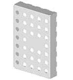
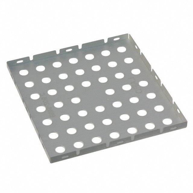
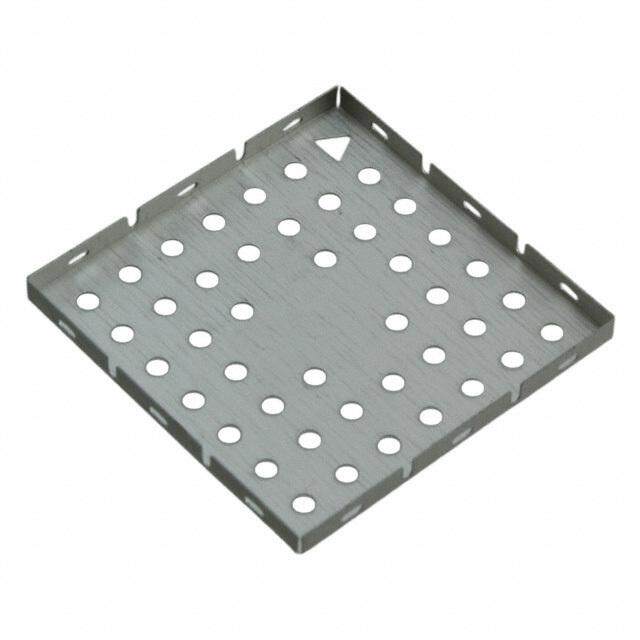
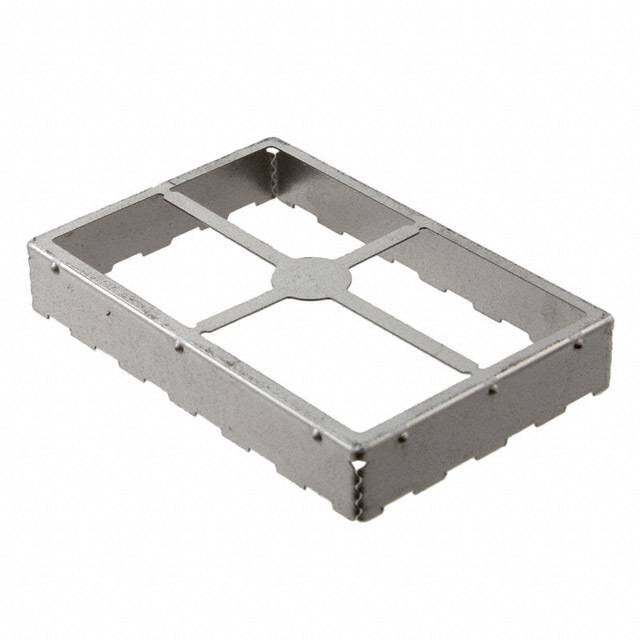
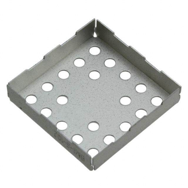
ICGOO电子元器件商城为您提供BMI-S-103由Laird Technologies设计生产,在icgoo商城现货销售,并且可以通过原厂、代理商等渠道进行代购。 BMI-S-103价格参考¥8.11-¥17.64。Laird TechnologiesBMI-S-103封装/规格:RF 屏蔽, RF Shield Shield, 1-Piece 1.032" (26.21mm) X 1.032" (26.21mm) Vent Holes in Pattern Solder。您可以下载BMI-S-103参考资料、Datasheet数据手册功能说明书,资料中有BMI-S-103 详细功能的应用电路图电压和使用方法及教程。
Laird Technologies EMI 的 BMI-S-103 属于 RF(射频)屏蔽产品系列,主要用于电子设备中的电磁干扰 (EMI) 和射频干扰 (RFI) 屏蔽。以下是该型号的主要应用场景:

 1. 移动通信设备
   - BMI-S-103 可用于手机、平板电脑和其他无线通信设备中,提供高效的射频屏蔽,减少内部组件之间的干扰,确保信号传输的稳定性和设备性能。

 2. 物联网 (IoT) 设备
   - 在智能家居、可穿戴设备和工业物联网设备中,BMI-S-103 能够保护敏感电路免受外部电磁干扰的影响,同时防止设备自身的射频信号泄漏。

 3. 汽车电子系统
   - 适用于车载信息娱乐系统、导航模块和通信模块等场景,确保汽车电子系统的正常运行,避免因电磁干扰导致的功能异常。

 4. 医疗设备
   - 在医疗领域,BMI-S-103 可用于心率监测仪、超声波设备和 MRI 系统等精密仪器中,提供可靠的射频屏蔽,保障设备的准确性和安全性。

 5. 航空航天与国防
   - 此型号适用于卫星通信、雷达系统和军用通信设备,能够有效隔离高频信号,防止信号泄露或受到外界干扰。

 6. 消费电子产品
   - 包括无线耳机、蓝牙音箱和智能手表等小型电子设备,BMI-S-103 提供紧凑型设计的屏蔽解决方案,满足高密度集成的需求。

 核心优势
- 高性能屏蔽:对高频射频信号具有优异的屏蔽效果。
- 灵活安装:适合多种尺寸和形状的应用环境。
- 可靠性强:能够在恶劣环境下保持稳定的屏蔽性能。
- 轻量化设计:适合便携式和小型化设备。

综上所述,BMI-S-103 广泛应用于需要高效射频屏蔽的各种电子设备中,帮助提升产品的可靠性和抗干扰能力。
| 参数 | 数值 |
| 产品目录 | |
| 描述 | BOARD SHIELD 1.032X1.032" 1PIECE |
| 产品分类 | |
| 品牌 | Laird Technologies EMI |
| 数据手册 | http://www.lairdtech.com/WorkArea/linkit.aspx?LinkIdentifier=id&ItemID=2924http://www.lairdtech.com/WorkArea/linkit.aspx?LinkIdentifier=id&ItemID=5765http://www.lairdtech.com/WorkArea/linkit.aspx?LinkIdentifier=id&ItemID=3282 |
| 产品图片 |
|
| 产品型号 | BMI-S-103 |
| rohs | 无铅 / 符合限制有害物质指令(RoHS)规范要求 |
| 产品系列 | - |
| 产品培训模块 | http://www.digikey.cn/PTM/IndividualPTM.page?site=cn&lang=zhs&ptm=25191 |
| 产品目录绘图 |
|
| 产品目录页面 | |
| 其它名称 | 903-1008-1 |
| 包装 | 剪切带 (CT) |
| 安装类型 | |
| 宽度-总 | 1.032"(26.21mm) |
| 标准包装 | 1 |
| 类型 | 1 件 |
| 通风 | 通风孔,按样式排列 |
| 长度-总 | 1.032"(26.21mm) |
| 高度-总 | 0.200" (5.08 mm) |


- 商务部:美国ITC正式对集成电路等产品启动337调查
- 曝三星4nm工艺存在良率问题 高通将骁龙8 Gen1或转产台积电
- 太阳诱电将投资9.5亿元在常州建新厂生产MLCC 预计2023年完工
- 英特尔发布欧洲新工厂建设计划 深化IDM 2.0 战略
- 台积电先进制程称霸业界 有大客户加持明年业绩稳了
- 达到5530亿美元!SIA预计今年全球半导体销售额将创下新高
- 英特尔拟将自动驾驶子公司Mobileye上市 估值或超500亿美元
- 三星加码芯片和SET,合并消费电子和移动部门,撤换高东真等 CEO
- 三星电子宣布重大人事变动 还合并消费电子和移动部门
- 海关总署:前11个月进口集成电路产品价值2.52万亿元 增长14.8%
PDF Datasheet 数据手册内容提取
EMI C A T A L O G w w w . l a i r d t e c h . c o m
ABOUT LAIRD Laird is a global technology business focused on enabling wireless communication and smart systems, and providing components and systems that protect electronics. Laird operates through two divisions, Wireless Systems and Performance Materials. Wireless Systems solutions include antenna systems, embedded wireless modules, telematics products and wireless automation and control solutions. Performance Materials solutions include electromagnetic interference shielding, thermal management and signal integrity products. As a leader in the design, supply and support of innovative technology, our products allow people, organisations, machines and applications to connect effectively, helping to build a world where smart technology transforms the way of life. Custom products are supplied to major sectors of the electronics industry including the handset, telecommunications, IT, automotive, public safety, consumer, medical, rail, mining and industrial markets. Providing value and differentiation to our customers though innovation, reliable fulfilment and speed, Laird PLC is listed and headquartered in London, and employs over 9,000 people in more than 58 facilities located in 18 countries. .
TABLE OF CONTENTS EMI INTRODUCTION 2 Fiber Optic Shield 40 GBIC Fiber Optic Shield 40 EMI SUMMARY 3 "D" Connector Shielding / Slotted "D" 41 Precision Stamped Metals 42 BOARD LEVEL SHIELDS 6 Contacts 42 Product Selection Guide 6 Custom Design 44 Introduction 8 Metals Galvanic Compatibility Chart 46 Standard Design Shields 9 EZ Peel™ 11 VENT PANELS 48 Rigid Corner 11 MaxAir™ 49 ReCovr™ 12 Elecro-Air™ 50 ReMovl 12 Electrovent™ 51 Overview 13 FABRIC-OVER FOAM 52 FINGERSTOCK 14 Product Selection Guide 52 Product Selection Guide 14 Introduction 54 Introduction 15 EcoGreen™ 56 Mounting Methods 16 I/O / Gasket Selection Guide 57 Ordering Information 17 Profile Selection Guide 58 UltraSoft® Series 18 I/O Selection Guide 62 Recyclable Clean Copper 18 Knitted Conductive Gaskets 65 Slot Mount Series 19 Visual Part Reference Guide 66 Dual Slot Series 21 Part Number Cross Reference 67 Teardrop Series 21 Ultraflex® 68 Compact PCI Symmetrical Mount 22 All Mesh 69 Alternate Slot Series 22 Elastomer Core 70 Variable Slot Mount 23 Electroground® EMI Washers 72 Symmetrical (S3) Slotted Shielding 24 Electromesh® Tape 75 Solid Top (S3) Symmetrical Slotted Shielding 25 Conductive Fabric 76 Clip-On Symmetrical Shielding 26 MRI "A" Fabric 77 No Snag Gasket 27 Conductive Tape 78 All-Purpose Series 28 Clip-On Series 29 ELECTRICALLY CONDUCTIVE ELASTOMERS 79 Low Profile Hook-On Gasket 31 Introduction 79 Low Profile Gasket 31 Product Selection Guide 80 Large Enclosure Series 32 Case Study 81 Double-Sided Contact Series 32 Visual Part Reference Guide 85 Foldover Series 33 Electroseal™ Conductive Elastomer 86 Stainless Steel I/O Shielding 33 Extrusions Guide 87 Flexible Low Compression Series 34 Gemini™ Coextrusions 93 Clip-On Twist Series 34 Fabricated Components Guide 95 Twist Series 35 Metal Impregnated Materials 99 Divider Edge Shielding 35 Specialty Products 102 Card Guide Clip-On 36 Automated Form-In-Place Gaskets 103 Clip-On Perpendicular Shielding 36 MICROWAVE ABSORBERS 105 Clip-On Perpendicular Grounding Strip 37 Product Selection Guide 105 Clip-On Longitudinal Grounding Strip 37 Design Guide 106 Mini-Longitudinal Grounding Gasket 38 Q-Zorb® 2000 HF 109 Longitudinal Grounding Series 38 Q-Zorb® 3000 HP 110 Custom Stamping 39 RFRET 4000 111 Contact Strips / Contact Rings 39 RFLS 5000 112 IEEE 1394 Horizontal Connector Gasket 39 Analysis, Test and Prototype Development 113 DIN Connector Series 39 USB Connector 40 www.lairdtech.com
TABLE OF CONTENTS EMI INTRODUCTION 2 Fiber Optic Shield 40 GBIC Fiber Optic Shield 40 EMI SUMMARY 3 "D" Connector Shielding / Slotted "D" 41 Precision Stamped Metals 42 BOARD LEVEL SHIELDS 6 Contacts 42 Product Selection Guide 6 Custom Design 44 Introduction 8 Metals Galvanic Compatibility Chart 46 Standard Design Shields 9 EZ Peel™ 11 VENT PANELS 48 Rigid Corner 11 MaxAir™ 49 ReCovr™ 12 Elecro-Air™ 50 ReMovl 12 Electrovent™ 51 Overview 13 FABRIC-OVER FOAM 52 FINGERSTOCK 14 Product Selection Guide 52 Product Selection Guide 14 Introduction 54 Introduction 15 EcoGreen™ 56 Mounting Methods 16 I/O / Gasket Selection Guide 57 Ordering Information 17 Profile Selection Guide 58 UltraSoft® Series 18 I/O Selection Guide 62 Recyclable Clean Copper 18 Knitted Conductive Gaskets 65 Slot Mount Series 19 Visual Part Reference Guide 66 Dual Slot Series 21 Part Number Cross Reference 67 Teardrop Series 21 Ultraflex® 68 Compact PCI Symmetrical Mount 22 All Mesh 69 Alternate Slot Series 22 Elastomer Core 70 Variable Slot Mount 23 Electroground® EMI Washers 72 Symmetrical (S3) Slotted Shielding 24 Electromesh® Tape 75 Solid Top (S3) Symmetrical Slotted Shielding 25 Conductive Fabric 76 Clip-On Symmetrical Shielding 26 MRI "A" Fabric 77 No Snag Gasket 27 Conductive Tape 78 All-Purpose Series 28 Clip-On Series 29 ELECTRICALLY CONDUCTIVE ELASTOMERS 79 Low Profile Hook-On Gasket 31 Introduction 79 Low Profile Gasket 31 Product Selection Guide 80 Large Enclosure Series 32 Case Study 81 Double-Sided Contact Series 32 Visual Part Reference Guide 85 Foldover Series 33 Electroseal™ Conductive Elastomer 86 Stainless Steel I/O Shielding 33 Extrusions Guide 87 Flexible Low Compression Series 34 Gemini™ Coextrusions 93 Clip-On Twist Series 34 Fabricated Components Guide 95 Twist Series 35 Metal Impregnated Materials 99 Divider Edge Shielding 35 Specialty Products 102 Card Guide Clip-On 36 Automated Form-In-Place Gaskets 103 Clip-On Perpendicular Shielding 36 MICROWAVE ABSORBERS 105 Clip-On Perpendicular Grounding Strip 37 Product Selection Guide 105 Clip-On Longitudinal Grounding Strip 37 Design Guide 106 Mini-Longitudinal Grounding Gasket 38 Q-Zorb® 2000 HF 109 Longitudinal Grounding Series 38 Q-Zorb® 3000 HP 110 Custom Stamping 39 RFRET 4000 111 Contact Strips / Contact Rings 39 RFLS 5000 112 IEEE 1394 Horizontal Connector Gasket 39 Analysis, Test and Prototype Development 113 DIN Connector Series 39 USB Connector 40 www.lairdtech.com
EMI ESSENTIALS EMI INTRODUCTION Overview of EMC/RFI Issues The phenomenon of electromagnetic interference (EMI) is familiar to virtually everyone, even if they do not understand the underlying principles. Most people have witnessed firsthand the effects of interference. To control EMI, government organizations, such as the FCC, CSA, and EEC, mandate that manufacturers may not design, produce or sell electronic equipment that jams the public broadcast services. In other instances, however, EMI can constitute more than a mere nuisance. The military and medical communities, for example, require trouble-free operation of their electronic equipment in adverse electromagnetic environments since malfunctions could jeopardize missions and personnel. The European Union’s EMC directive also mandates that “the apparatus has an adequate level of intrinsic immunity to electromagnetic disturbance to enable it to operate as intended”. EMC Design of High Speed Systems The interference and susceptibility (immunity) effects of electronic apparatus are created by time-variant electromagnetic fields which may be propagated along a conducting medium or by radiation through space. Because the source of the conducted and radiated interference energy levels may be related, a coordinated systems design effort is required to reduce these effects. A design program for an equipment item that must meet both an emission and an immunity requirement consists of: • Suppression: Reducing the interference at its source. • Isolation: Isolating the offending circuits by filtering, grounding and shielding. • Desensitization: Increasing the immunity of any susceptible circuits. These three steps should be carried on throughout the entire equipment design and implemented as early as possible within the design program. Effects of Logic Speed The trend in today’s electronic devices is faster, smaller, and digital rather than analog. Most equipment (95%) of today contains digital circuits. Today’s digital designer must create a circuit board that has the lowest possible EMI, combined with the highest possible operating/processing speeds. Design of the PCB is the most critical EMC influencing factor for any system, since virtually all active devices are located on the board. It is the changing current (accelerated electron movement) produced by the active devices that result in EMI. Design Approaches There are two approaches that can be used to reduce the emission from the PC board. The first approach is to operate the circuit at the slowest speeds consistent with the functionality of the system, lay out the PCB with the smallest possible loop areas (especially the high speed devices), and insert suppression components such as filters, ferrite beads, and bypass capacitors into the circuit to reduce its bandwidth. These techniques will result in a desired decrease in the high frequency harmonic amplitudes and circuit bandwidth and a corresponding undesired decrease in both the operating speed and system reliability. The use of slower speeds with reduced bandwidth will help to desensitize the circuit to external susceptibility fields. The second is to use shielding. Shielding is the only non-invasive suppression technique. Since the shielding is not inserted into the circuit, it does not affect the high frequency operating speed of the system, nor does it affect the operation of the system should changes be made to the design in the future. In addition, shielding does not create timing problems and waveform distortion; it does not decrease system reliability; and it reduces crosstalk. Plus, shielding works for both emission suppression as well as susceptibility (immunity) problems. Even with the overall advantages of shielding, the most cost-effective approach is to use a combination 2 of circuit suppression/hardening and shielding. www.lairdtech.com
Fabric-Over-Foam and Conductive Foam Wire Mesh Tape Applications • Shielding or grounding of computer and • Covers opened infrequently for servicing • Design flexibility provides grounding and telecommunication equipment seams (6-12 times per year) shielding solutions for I/O shielding panels, and apertures • Long lasting resiliency is ideal for highly disk drive insulators, ground planes or circuit sensitive components in permanent or boards, electromedical devices, keyboard semi-permanent enclosures devices • Consistent point-to-point contact for high • Mask-and-peel tape for painted electronic shielding effectiveness over the life of the enclosures gasket • Cable and wire harness wrapping Features and Benefits • UL 94VO and HB flame retardant • Most economical gasket for low-cycling • Simple installation Product Highlights • Ideal for applications requiring low applications • Ideally suited for thin or low-profile pressure force • High shielding effectiveness over broad applications • Self-terminating cut-to lengths frequency range • Conductive foil tape with release mask for • High conductivity and shielding attenuation • Available in wide variety of sizes and shapes painted enclosures • Galvanically-compatible with most mating • Knit construction for long lasting resiliency • Tin copper cloth and nickel copper cloth surfaces • Versatile mounting options versions provide easy-to-handle alternatives • High abrasion and shear resistance • Available with elastomer gasket for moisture to foils and dust sealing Electrical Shielding >85 dB 90 - 105 dB — Effectiveness Transfer Impedance (500 MHz) H-field (200 MHz) 30 - 45 dB 55 - 65 dB — Modified Mil 285 Plane Wave (2 GHz) 90 - 100 dB 80 - 115 dB 85 - 95 dB Modified Mil 285 Surface Resistivity <0.07 ohms/square N/A Low surface resistivity based on material selection Volume Resistivity N/A 0.0004 - 0.114 ohm-cm N/A Mechanical Height: 0.015 - 0.945 (0,038 - 24,0) Height: 0.062 - 0.500 (1,57 - 12,7) Width: 0.025 - 2.00 (6,4 - 50,8) Available Size Range Thickness: 0.003 - 0.007 (0,08 - 0,18) Deflection Operating Range 20 - 75% deflection 20 - 70% deflection N/A Compression Force 3 - 10 Ibs/in. ft. (4,5 - 15,0 Kg/m) From 6 - 50 Ibs/in. ft. N/A (based on shape selection) @ 20% deflection (dependent on foam (8,8 - 74 Kg/m) round selection and shape) Compression Set <4 - 20% @ 50% deflection 10% @ 20% compression N/A Joint Unevenness 0.020 - 0.050 (0,51 - 1,27) 0.010 - 0.300 (0,25 - 7,6) N/A Accommodation Compound/Material Cover: Flame retardant metallized Ni/Cu, BeCu, Monel, aluminum, tin-plated steel, Tin-plated copper, copper foil, nickel copper Availability Tin/Cu and silver woven or non-woven textile. tin-plated brass, Enviroseal version with cloth tape Core: Flame retardant urethane, TPE neoprene or silicone Temperature Range -40 - 158°F (-40 - 70°C) Enviroseal -103 - 500°F (-75 - 260°C) 50 - 500°F (10 - 260°C) based on material selection Available Profiles Round, rectangular, square “D”, “C”, “J”, “P”, Round, rectangular, square, single-round with Rolls “U”, clip-on, knife edge fin, double-round with fin Mounting Methods Groove, PSA, clip-on, dart Groove, pressure-sensitive adhesive, Pressure-sensitive adhesive, conductive or mechanical fasteners, channel mount non-conductive Custom Shapes Available Cut-to lengths, mitered and spliced corners, Cut-to lengths, mitered corners, flat tape, and Die-cut shapes kiss-cut, other profiles EMI washers Environmental N/A Enviroseal product only: moisture, rain N/A Fluid Seal Air/Dust Provides barrier against dust Enviroseal product only N/A Galvanic Compatibility Compatible with a wide variety of mating Variety of platings to ensure galvanic Wide variety of materials available to meet surfaces—zinc, aluminum, stainless steel, etc. compatibility with mating surface galvanic compatibility requirements 3 wwwwww..llaaiirrddtteecchh..ccoomm
Fingerstock Board-Level Shields Vent Panels and Filters Form-In-Place Electrically Conductive Elastomers Oriented Wire Microwave Absorbers Applications • Ideal for high-cycling applications requiring • All applications that require shielding of • Provides air flow for component cooling and a barrier to • Ideal for applications with miniature • EMI and environmental sealing applications • Providing both EMI shielding and an • Antenna sidelobe reduction frequent access board- level components reduce RF leakage electrical housings, thin wall where flat or groove mounting surface re- environmental seal on cast or machined • Surface current suppression • Ideal in wiping applications when gasket needs • Low height down to 0.04 (1,0) • Sizes range from small muffin fans on desktops to large construction, and intricate multi- quires a complex molded or extruded shape surfaces • Applied directly to the top of high-speed to be engaged from either the top or side accommodating mother/daughter board room-size facilities components (i.e., cell phones, hand- • Vulcanized frame configurations can be CPUs, LSIs, and ICs • Wide variety of profiles and mounting methods configurations • Available in commercial and military grade materials held devices, medical instrumentation used with pre-cast housings, vent panels, • Crosstalk suppression accommodating applications from small hand- • Secure cover design ideal for applications and equipment) and computer terminal window frames • Improves antenna gain in RFID held devices to room-size enclosures subject to shock and vibration such as • Die-cut wall widths as low as 0.090 applications mobile military vehicles, commercial aircraft, (2,27) for circular military connectors • Radar cross-section reduction and wireless electronics and D-sub connectors Features and Benefits • Large selection of sizes and shapes • Custom shapes available • Available in a wide range of materials and platings • Automated process offers cost savings • Meets military and commercial standards • Provides both EMI and moisture seal • Higher frequency use than traditional shielding Product Highlights • Wide mechanical operating range • Provides isolation of board-level that meet a broad range of shielding effectiveness on raw material, labor and assembly time • Provides EMI and environmental shielding • Available in sponge or solid silicone with • Frequency range extended used with other • Superior performance at elevated temperatures components requirements • Small dimension which provide critical • Extruded shapes ideal for extremely narrow Monel or aluminum wire shielding • High shielding effectiveness levels • Minimizes crosstalk and susceptibility • Varied mounting configurations meeting packaging space for board level mounting surfaces • Can be die-cut in complex shapes • Variety of types for custom solutions • Ideal for high-cycle applications without impacting system speed environmental space criteria components • Custom die-cut and molding available • Monel wire bonded into the silicone • Easy installation into noisy cavities • Good design flexibility with either wiping action • Available in tape-and-reel for automated • Available protective grille for high traffic areas • Fast prototyping and turn over to mass • Wide variety of material compounds for provides multiple spring effect with each with pressure-sensitive adhesive or in compression pick-and-place applications • Provides cooling of electronic equipment while production galvanic compatibility to mounting surfaces contact point resulting in low compres- • EMI and radar cross-section reduction • For use in a wide variety of slotted and • ReCovr/ReMovl features available for maintaining EMI integrity of enclosure • Various bead size and cross section • High corrosion-resistant compounds available sion set • Internal EMI and cavity resonance reduction, grounding contact applications convenient component access. • MaxAir vent panels offer 10-20% additional airflow shape available used in conjunction with board-level shielding over frames Al vent panels • Dispense on metal or plastics Electrical Shielding 80 - 100 dB — — 85 - 120 dB 40 - 105 dB 60 - 100 dB N/A Effectiveness Transfer Impedance (500 MHz) H-field (200 MHz) 60 - 70 dB 48 dB 40 - 70 dB 50 - 70 dB 30 - 75 dB 25 - 60 dB N/A Modified Mil 285 Plane Wave (2 GHz) 75 - 120 dB 40 - 60 dB 45 - 115 dB 70 - 100 dB 40 - 120 dB 30 - 95 dB N/A Modified Mil 285 Surface Resistivity N/A N/A N/A N/A N/A N/A N/A Volume Resistivity N/A N/A N/A 0.002 - 0.03 ohm-cm 0.002 - 5 ohm-cm 0.006 ohm-cm N/A Mechanical Selection of various sizes and configurations Fence and lid: 0.130 - 1.00 (3,3 - 25,4) height Thickness: 0.25 - 0.500 (6,35 - 12,7) Height: 0.014 - 0.090 (0,36 - 2,3) Sheet: 0.020 (0,51) - 0.125 (3,17) thick Thickness: 0.032 - 0.250 (0,81 - 6,35) Offered in sheets as a die-cut or kiss-cut Available Size Range to accommodate gaps from 0.010 - 0.400 6.000 (152,4) width Width: 0.020 - 0.125 (0,5 - 3,1) O-strip: 0.040 (1,02) - 0.250 (6,35) dia. component (0,25 - 10,2) One-piece construction: 0.04 - 0.25 (1,0 - 6,4) O-tubing: 0.090 (2,28) O.D. x 0.050 (1,27) I.D. height, 0.250 - 0.375 (6,35 - 9,53) width to 0.4371 (11,10) O.D. x 0.250 (6,35) I.D. Deflection Operating Range 20 - 80% deflection, N/A N/A 15 - 20% deflection Sheet: 10% deflection 10 - 20% deflection N/A Maximum deflection is dependent on the part Solid extrusions: 10 -25% deflection profile Hollow extrusions: 20 - 50% deflection Compression Force UltraSoft® 98 Series: 1.6 Ibs/in. ft. N/A N/A 1.5 Ibs/in. ft. (0,27 Kg/cm) @ Sheet: 75 - 100 PSI (516,7 - 689 kPa) 25 - 100 PSI N/A (based on shape selection) (2,4 Kg/m) to 41 Ibs/in. ft. (61 Kg/m) 0.222 (0,56) height @ 20% deflection (125 - 689 KPa) Standard 97 Series: 3.1 Ibs/in. ft. (4.6 Kg/m) to 118 Ibs/in. ft. (176 Kg/m) Compression Set None within operating range N/A N/A <20% @ 50% deflection 15 - 50% @ 50% deflection 2 - 5% @ 50 PSI (344,5 KPa) N/A Joint Unevenness 0.003 - 0.350 (0,08 - 8,89) maximum N/A N/A 0.002 - 0.006 (0,05 - 0,15) Sheet: 0.005 - 0.010 (0,13 - 0,25) 0.005 - 0.015 (0,13 - 0,38) N/A Accommodation Tubing: 0.005 - 0.300 (0,13 - 7,6) Compound/Material Standard material is Beryllium Copper, other Tin-plated phosphor bronze, tin-coated steel, Gasket material: Monel, tin/copper/steel, BeCu, Elastomer silicone fillers: Ag/Al, Ag/ Compounds that meet MIL-G-83528: Elastomer: solid or sponge silicone Microwave absorbing elastomers (Q-Zorb) Availability beryllium free variants on request stainless steel, brass, BeCu, and nickel silver; metallized fabric-over-foam Cu, Ag/Ni, Ni/graphite Elastomers: silicone, fluorosilicone, EPDM Wire: Monel, aluminum are offered in silicone; microwave absorber other materials also available Fingerstock frame: aluminum alloy, steel, brass Fillers: Ag, Ag/Cu, Ag/Al, Ag/Ni, Ag/Gl, CAR, foam is urethene-based, open-celled foam Honeycomb material: aluminum, steel, brass, Ni/graphite. metallized polymeric Available in NASA-specified ES75 compounds for outgassing Temperature Range Continuous operation @ 250°F (121°C) Withstands reflow and solder temperature N/A -58 - 212°F (-50 - 100°C) -67 to 302°F (-55 to 150°C) 80 - 500°F (26 - 260°C) Q-Zorb: -85 - 350°F (-65 - 175°C) RF foam: -85 - 250°F (-65 - 120°C) Available Profiles Over 350 standard shapes available, as well Squares, rectangles, L-shapes, 90° inside N/A “D” shape bead Solid extrusions: rectangular, round ,“D”, and U-channel Rectangular, strip, flat sheets; die-cut Q-Zorb thickness: 0.006 - 0.375 (0,15 - 9,53) as cut-to lengths and modified standards that corners, and other custom shapes Hollow extrusions: square, round, “D”, “P”, modified shapes RF Foam thickness: 0.125 - 0.250 (3,18 - 6,35) include finger removal, notches, punch holes, etc. standards, cut-to length sheets Mounting Methods Clip-on, Sticky Fingers® (pressure-sensitive Surface mount/thru-hole, various pin styles Captive fastener thru-holes Directly applied to mounting surface Groove, pressure-sensitive adhesive, channel Groove, pressure-sensitive adhesive Pressure-sensitive adhesive adhesive tape), rivet, weld, solder, and slot mount available clip- on, mechanical fastening Custom Shapes Available Custom designs to meet specific applications Flexible fence with flat lid, photo etched Available in circular configurations and Infinite variety of patterns and larger Large variation on extruded shapes, complex Complex die-cut shapes, bonded or Infinite die-cut shapes and molded parts flat blanks for hand forming, solid can custom shapes custom bead sizes die-cuts, and molded parts vulcanized construction, supplied with dividers to provide isolation Environmental None N/A Drip-proof versions available Moisture, rain seal Moisture, rain, jet fuel, and nuclear biological Moisture and rain Moisture, rain, jet fuel, and nuclear Fluid Seal chemical (NBC) UL compounds biological chemical (NBC) UL compounds Air/Dust Limited to twist series with Poron seal N/A 95% open area for minimal pressure drop In limited applications Excellent sealing against air and dust Provides barrier against dust Available in limited applications Galvanic Compatibility Over 20 plating finishes available to ensure Compatible with all solder materials Gasket materials compatible with wide variety of Available in four compounds to provide 21 standard variations Monel and aluminum wire are compatible Moisture, rain, jet fuel, and nuclear galvanic compatibility with mating surface plated surfaces galvanic compatibility with most mating with a broad range of mating surfaces biological chemical (NBC) UL compounds 4 materials www.lairdtech.com
Fingerstock Board-Level Shields Vent Panels and Filters Form-In-Place Electrically Conductive Elastomers Oriented Wire Microwave Absorbers Applications • Ideal for high-cycling applications requiring • All applications that require shielding of • Provides air flow for component cooling and a barrier to • Ideal for applications with miniature • EMI and environmental sealing applications • Providing both EMI shielding and an • Antenna sidelobe reduction frequent access board- level components reduce RF leakage electrical housings, thin wall where flat or groove mounting surface re- environmental seal on cast or machined • Surface current suppression • Ideal in wiping applications when gasket needs • Low height down to 0.04 (1,0) • Sizes range from small muffin fans on desktops to large construction, and intricate multi- quires a complex molded or extruded shape surfaces • Applied directly to the top of high-speed to be engaged from either the top or side accommodating mother/daughter board room-size facilities components (i.e., cell phones, hand- • Vulcanized frame configurations can be CPUs, LSIs, and ICs • Wide variety of profiles and mounting methods configurations • Available in commercial and military grade materials held devices, medical instrumentation used with pre-cast housings, vent panels, • Crosstalk suppression accommodating applications from small hand- • Secure cover design ideal for applications and equipment) and computer terminal window frames • Improves antenna gain in RFID held devices to room-size enclosures subject to shock and vibration such as • Die-cut wall widths as low as 0.090 applications mobile military vehicles, commercial aircraft, (2,27) for circular military connectors • Radar cross-section reduction and wireless electronics and D-sub connectors Features and Benefits • Large selection of sizes and shapes • Custom shapes available • Available in a wide range of materials and platings • Automated process offers cost savings • Meets military and commercial standards • Provides both EMI and moisture seal • Higher frequency use than traditional shielding Product Highlights • Wide mechanical operating range • Provides isolation of board-level that meet a broad range of shielding effectiveness on raw material, labor and assembly time • Provides EMI and environmental shielding • Available in sponge or solid silicone with • Frequency range extended used with other • Superior performance at elevated temperatures components requirements • Small dimension which provide critical • Extruded shapes ideal for extremely narrow Monel or aluminum wire shielding • High shielding effectiveness levels • Minimizes crosstalk and susceptibility • Varied mounting configurations meeting packaging space for board level mounting surfaces • Can be die-cut in complex shapes • Variety of types for custom solutions • Ideal for high-cycle applications without impacting system speed environmental space criteria components • Custom die-cut and molding available • Monel wire bonded into the silicone • Easy installation into noisy cavities • Good design flexibility with either wiping action • Available in tape-and-reel for automated • Available protective grille for high traffic areas • Fast prototyping and turn over to mass • Wide variety of material compounds for provides multiple spring effect with each with pressure-sensitive adhesive or in compression pick-and-place applications • Provides cooling of electronic equipment while production galvanic compatibility to mounting surfaces contact point resulting in low compres- • EMI and radar cross-section reduction • For use in a wide variety of slotted and • ReCovr/ReMovl features available for maintaining EMI integrity of enclosure • Various bead size and cross section • High corrosion-resistant compounds available sion set • Internal EMI and cavity resonance reduction, grounding contact applications convenient component access. • MaxAir vent panels offer 10-20% additional airflow shape available used in conjunction with board-level shielding over frames Al vent panels • Dispense on metal or plastics Electrical Shielding 80 - 100 dB — — 85 - 120 dB 40 - 105 dB 60 - 100 dB N/A Effectiveness Transfer Impedance (500 MHz) H-field (200 MHz) 60 - 70 dB 48 dB 40 - 70 dB 50 - 70 dB 30 - 75 dB 25 - 60 dB N/A Modified Mil 285 Plane Wave (2 GHz) 75 - 120 dB 40 - 60 dB 45 - 115 dB 70 - 100 dB 40 - 120 dB 30 - 95 dB N/A Modified Mil 285 Surface Resistivity N/A N/A N/A N/A N/A N/A N/A Volume Resistivity N/A N/A N/A 0.002 - 0.03 ohm-cm 0.002 - 5 ohm-cm 0.006 ohm-cm N/A Mechanical Selection of various sizes and configurations Fence and lid: 0.130 - 1.00 (3,3 - 25,4) height Thickness: 0.25 - 0.500 (6,35 - 12,7) Height: 0.014 - 0.090 (0,36 - 2,3) Sheet: 0.020 (0,51) - 0.125 (3,17) thick Thickness: 0.032 - 0.250 (0,81 - 6,35) Offered in sheets as a die-cut or kiss-cut Available Size Range to accommodate gaps from 0.010 - 0.400 6.000 (152,4) width Width: 0.020 - 0.125 (0,5 - 3,1) O-strip: 0.040 (1,02) - 0.250 (6,35) dia. component (0,25 - 10,2) One-piece construction: 0.04 - 0.25 (1,0 - 6,4) O-tubing: 0.090 (2,28) O.D. x 0.050 (1,27) I.D. height, 0.250 - 0.375 (6,35 - 9,53) width to 0.4371 (11,10) O.D. x 0.250 (6,35) I.D. Deflection Operating Range 20 - 80% deflection, N/A N/A 15 - 20% deflection Sheet: 10% deflection 10 - 20% deflection N/A Maximum deflection is dependent on the part Solid extrusions: 10 -25% deflection profile Hollow extrusions: 20 - 50% deflection Compression Force UltraSoft® 98 Series: 1.6 Ibs/in. ft. N/A N/A 1.5 Ibs/in. ft. (0,27 Kg/cm) @ Sheet: 75 - 100 PSI (516,7 - 689 kPa) 25 - 100 PSI N/A (based on shape selection) (2,4 Kg/m) to 41 Ibs/in. ft. (61 Kg/m) 0.222 (0,56) height @ 20% deflection (125 - 689 KPa) Standard 97 Series: 3.1 Ibs/in. ft. (4.6 Kg/m) to 118 Ibs/in. ft. (176 Kg/m) Compression Set None within operating range N/A N/A <20% @ 50% deflection 15 - 50% @ 50% deflection 2 - 5% @ 50 PSI (344,5 KPa) N/A Joint Unevenness 0.003 - 0.350 (0,08 - 8,89) maximum N/A N/A 0.002 - 0.006 (0,05 - 0,15) Sheet: 0.005 - 0.010 (0,13 - 0,25) 0.005 - 0.015 (0,13 - 0,38) N/A Accommodation Tubing: 0.005 - 0.300 (0,13 - 7,6) Compound/Material Standard material is Beryllium Copper, other Tin-plated phosphor bronze, tin-coated steel, Gasket material: Monel, tin/copper/steel, BeCu, Elastomer silicone fillers: Ag/Al, Ag/ Compounds that meet MIL-G-83528: Elastomer: solid or sponge silicone Microwave absorbing elastomers (Q-Zorb) Availability beryllium free variants on request stainless steel, brass, BeCu, and nickel silver; metallized fabric-over-foam Cu, Ag/Ni, Ni/graphite Elastomers: silicone, fluorosilicone, EPDM Wire: Monel, aluminum are offered in silicone; microwave absorber other materials also available Fingerstock frame: aluminum alloy, steel, brass Fillers: Ag, Ag/Cu, Ag/Al, Ag/Ni, Ag/Gl, CAR, foam is urethene-based, open-celled foam Honeycomb material: aluminum, steel, brass, Ni/graphite. metallized polymeric Available in NASA-specified ES75 compounds for outgassing Temperature Range Continuous operation @ 250°F (121°C) Withstands reflow and solder temperature N/A -58 - 212°F (-50 - 100°C) -67 to 302°F (-55 to 150°C) 80 - 500°F (26 - 260°C) Q-Zorb: -85 - 350°F (-65 - 175°C) RF foam: -85 - 250°F (-65 - 120°C) Available Profiles Over 350 standard shapes available, as well Squares, rectangles, L-shapes, 90° inside N/A “D” shape bead Solid extrusions: rectangular, round ,“D”, and U-channel Rectangular, strip, flat sheets; die-cut Q-Zorb thickness: 0.006 - 0.375 (0,15 - 9,53) as cut-to lengths and modified standards that corners, and other custom shapes Hollow extrusions: square, round, “D”, “P”, modified shapes RF Foam thickness: 0.125 - 0.250 (3,18 - 6,35) include finger removal, notches, punch holes, etc. standards, cut-to length sheets Mounting Methods Clip-on, Sticky Fingers® (pressure-sensitive Surface mount/thru-hole, various pin styles Captive fastener thru-holes Directly applied to mounting surface Groove, pressure-sensitive adhesive, channel Groove, pressure-sensitive adhesive Pressure-sensitive adhesive adhesive tape), rivet, weld, solder, and slot mount available clip- on, mechanical fastening Custom Shapes Available Custom designs to meet specific applications Flexible fence with flat lid, photo etched Available in circular configurations and Infinite variety of patterns and larger Large variation on extruded shapes, complex Complex die-cut shapes, bonded or Infinite die-cut shapes and molded parts flat blanks for hand forming, solid can custom shapes custom bead sizes die-cuts, and molded parts vulcanized construction, supplied with dividers to provide isolation Environmental None N/A Drip-proof versions available Moisture, rain seal Moisture, rain, jet fuel, and nuclear biological Moisture and rain Moisture, rain, jet fuel, and nuclear Fluid Seal chemical (NBC) UL compounds biological chemical (NBC) UL compounds Air/Dust Limited to twist series with Poron seal N/A 95% open area for minimal pressure drop In limited applications Excellent sealing against air and dust Provides barrier against dust Available in limited applications Galvanic Compatibility Over 20 plating finishes available to ensure Compatible with all solder materials Gasket materials compatible with wide variety of Available in four compounds to provide 21 standard variations Monel and aluminum wire are compatible Moisture, rain, jet fuel, and nuclear galvanic compatibility with mating surface plated surfaces galvanic compatibility with most mating with a broad range of mating surfaces biological chemical (NBC) UL compounds 5 materials www.lairdtech.com All dimensions are in inches (millimeters) unless otherwise specified.
EMI ESSENTIALS BOARD LEVEL SHIELDS PRODUCT SELECTION GUIDE Corner Feature Unique Product Mounting Features Size & Shape Features Traditional Rigid Full Drawn Full Drawn ReMovl Pick & SMT Thru Hole Pins, Tabs, Interior Typical Low Height Typical Flatness Folded Corner w/ Flange Zero Flange Place Bridge Castellations Loc Pins Etc. Walls Material (less than 2 Length (Size Dep) Thickness mm) & Width Improves Flatness Most mechanically rigid, Similar to Full Easy removal of pick Through hole style by increasing but depth attainable is Drawn, Tooling and place bridge for pin that engages torsional rigidity material and configuration more complex. post reflow inspection to underside of BLS Design Key Attributes & dependent PCB by mechanical Type / Features Application Consideration engagement. SINGLE PIECE Single Piece Simple low cost BLS Solution Opt Std Opt (height/matl limits) Opt N/A Std Opt Opt No 0.2 Yes 10- 75 mm 0.08 TWO PIECE Traditional Post Reflow Component Access for inspect, test, cleaning, etc. Various Frame cover retention features available Opt Std Opt (height/matl limits) Low Height Opt Std Opt Opt Opt 0.2 Yes 10- 75 mm 0.08 to address rattling, EMI, and shock/ Option vibration concerns. Cover Std Opt Opt (height/matl limits) N/A N/A N/A N/A N/A N/A 0.15 Yes 10- 75 mm 0.15 Optional pre-assembled deliverable ReCovr Lower total cost 2 piece solution. N/A Req'd N/A N/A N/A Std N/A Opt No 0.3 No 10-40 mm 0.1 Eaveless side wall for maximum component access. EZ Peel Support for legacy products. Std N/A Opt N/A Std N/A Opt No 0.12 Yes 10-30 mm 0.1 ReCovr can often be a more reliable alternative. EZ Peel can utilize a separate replacement cover if desired. 97-2000 Large BLS Applications. Can accommodate internal walls for Frame N/A N/A N/A N/A N/A Std Opt Opt Opt 0.4 No 50-300 mm 0.2 EMI compartmentation. Cover Std N/A N/A N/A N/A N/A N/A N/A 0.25 0.25 No 50-300 mm 0.2 BLS MATERIALS Material Type Description / Specs Comments Cost Position Applications MATRIX CRS, Tin Plated 1010 / 1008 CRS High Permeability Material for low Freq Applications, Very Good Solderability, Best Most common BLS solutions Mitigation options for Tin Whisker Growth, Pre-plated, Bare stamped edges Nickel Silver CA770, CA752 Environmental Performance & Aesthetic Quality, Good Mechanical / Good Hi Performance BLS solutions Strength Properties, Good Solderability, Active Flux may be required (Mechanical & Environmental) Stainless Steel Typical 301 and 316 Series Environmental Performance, Good option for the cover of 2 piece designs Better BLS Covers, Specialty Military Copper Alloys Phosphor Bronze, Beryllium Copper, Brass Can be chosen for unique requirements that integrate spring contacts, Good Specialty BLS applications 6 Typically Plated for Solderability and/or corrosion resistance Integrated Spring Contacts www.lairdtech.com
EMI ESSENTIALS Corner Feature Unique Product Mounting Features Size & Shape Features Traditional Rigid Full Drawn Full Drawn ReMovl Pick & SMT Thru Hole Pins, Tabs, Interior Typical Low Height Typical Flatness Folded Corner w/ Flange Zero Flange Place Bridge Castellations Loc Pins Etc. Walls Material (less than 2 Length (Size Dep) Thickness mm) & Width Improves Flatness Most mechanically rigid, Similar to Full Easy removal of pick Through hole style by increasing but depth attainable is Drawn, Tooling and place bridge for pin that engages torsional rigidity material and configuration more complex. post reflow inspection to underside of dependent PCB by mechanical engagement. Single Piece Simple low cost BLS Solution Opt Std Opt (height/matl limits) Opt N/A Std Opt Opt No 0.2 Yes 10- 75 mm 0.08 Traditional Post Reflow Component Access for inspect, test, cleaning, etc. Various Frame cover retention features available Opt Std Opt (height/matl limits) Low Height Opt Std Opt Opt Opt 0.2 Yes 10- 75 mm 0.08 to address rattling, EMI, and shock/ Option vibration concerns. Cover Std Opt Opt (height/matl limits) N/A N/A N/A N/A N/A N/A 0.15 Yes 10- 75 mm 0.15 Optional pre-assembled deliverable ReCovr Lower total cost 2 piece solution. N/A Req'd N/A N/A N/A Std N/A Opt No 0.3 No 10-40 mm 0.1 Eaveless side wall for maximum component access. EZ Peel Support for legacy products. Std N/A Opt N/A Std N/A Opt No 0.12 Yes 10-30 mm 0.1 ReCovr can often be a more reliable alternative. EZ Peel can utilize a separate replacement cover if desired. 97-2000 Large BLS Applications. Can accommodate internal walls for Frame N/A N/A N/A N/A N/A Std Opt Opt Opt 0.4 No 50-300 mm 0.2 EMI compartmentation. Cover Std N/A N/A N/A N/A N/A N/A N/A 0.25 0.25 No 50-300 mm 0.2 Material Type Description / Specs Comments Cost Position Applications CRS, Tin Plated 1010 / 1008 CRS High Permeability Material for low Freq Applications, Very Good Solderability, Best Most common BLS solutions Mitigation options for Tin Whisker Growth, Pre-plated, Bare stamped edges Nickel Silver CA770, CA752 Environmental Performance & Aesthetic Quality, Good Mechanical / Good Hi Performance BLS solutions Strength Properties, Good Solderability, Active Flux may be required (Mechanical & Environmental) Stainless Steel Typical 301 and 316 Series Environmental Performance, Good option for the cover of 2 piece designs Better BLS Covers, Specialty Military Copper Alloys Phosphor Bronze, Beryllium Copper, Brass Can be chosen for unique requirements that integrate spring contacts, Good Specialty BLS applications Typically Plated for Solderability and/or corrosion resistance Integrated Spring Contacts 7 www.lairdtech.com
EMI ESSENTIALS BOARD LEVEL SHIELDS Whether it’s a one-piece shield, multi-compartmental shield or precision contact, each solution Laird delivers is designed to provide maximum performance within a minimum timeline. Laird produces metal electronic components for surface mount applications in a variety of industries. Laird expertise in a number of key areas ensures that the part provided not only performs, but also optimizes applications. After determining the right board level shield or contact design for an application, Laird experts use the latest systems to develop part designs in just hours. Laird experienced engineers and technical specialists look beyond the component to the total application. They work with you to engineer the ideal finished product at the best value. 8 www.lairdtech.com
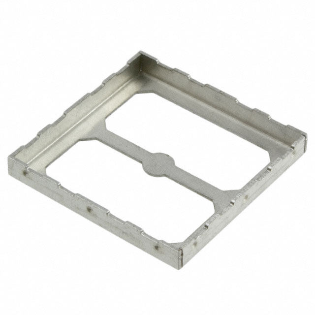
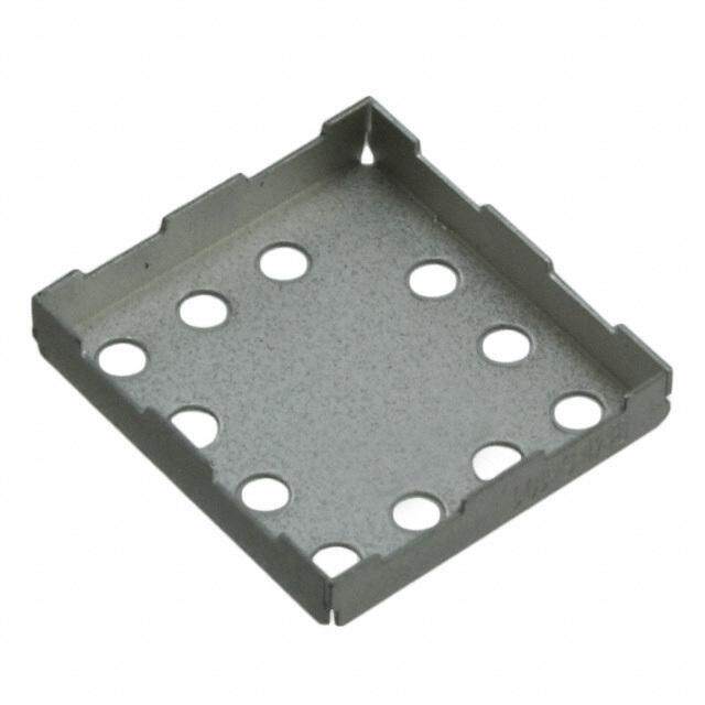
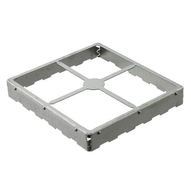
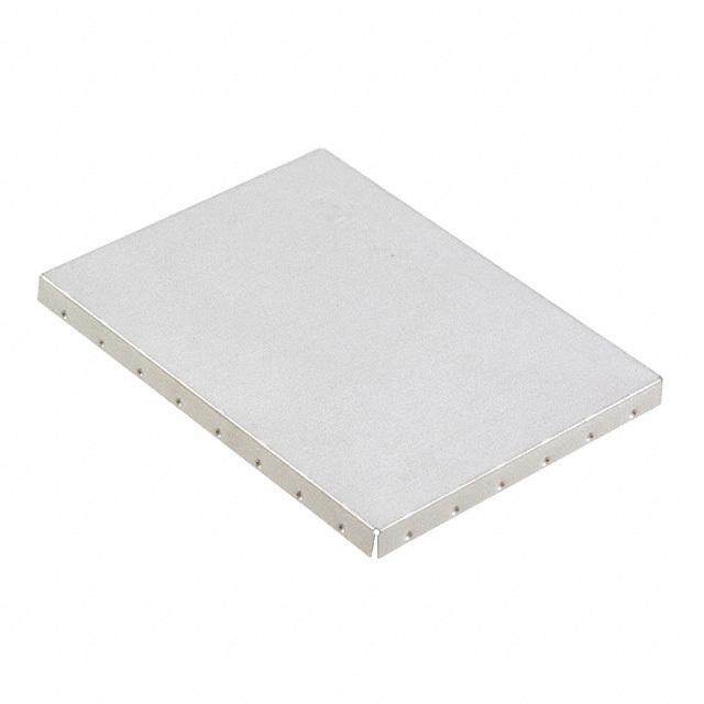
EMI ESSENTIALS BOARD LEVEL SHIELDS STANDARD DESIGN SHIELDS STANDARD SURFACE MOUNT SHIELDS — ONE-PIECE Off the Shelf, On Spec and On Budget Standard surface mount shields are available in both one-piece and two-piece designs. One-piece shields offer six sides of protection, with the sixth side being the board itself. One-piece designs offer economical shielding protection where access to covered components is not necessary. There are no tooling costs associated with either the one and/or two-piece standard design. TYPICAL PROPERTIES AND PERFORMANCE ALL PART NUMBERS Features and Benefits: • Available in both one-piece PROPERTY TEST METHOD RESULT and two-piece designs Co-planarity LTWI-1119 < 0.10 mm • One-piece designs offer economical Solderability ANSI/JSTD-002 >99% shielding protection • No tooling costs associated with one Solderability MIL-STD-202 Method 208 >99% or two-piece standard designs Surface mount solderability ANSI/EIA 638 Passes Appearance LTIES-125 Passes Adhesion ASTM B-571 Passes 3 Axis mechanical shock LTES-461 Passes STANDARD ONE-PIECE BOARD LEVEL SHIELDS PART MAXIMUM MAXIMUM MAXIMUM PARTS NUMBER OVERALL OVERALL OVERALL PER REEL LENGTH WIDTH HEIGHT in (mm) in (mm) in (mm) BMI-S-101 .538 .476 .100 1000 (13,66) (12,10) (2,54) BMI-S-102 .650 .650 .142 700 (16,50) (16,50) (3,60) BMI-S-103 1.032 1.032 .200 300 (26,21) (26,21) (5,08) BMI-S-104 1.260 1.260 .236 225 (32,00) (32,00) (6,00) BMI-S-105 1.500 1.000 .236 250 (38,10) (25,40) (6,00) BMI-S-106 1.450 1.326 .200 300 (36,83) (33,68) (5,08) BMI-S-107 1.747 1.747 .384 120 (44,37) (44,37) (9,75) BMI-S-111 1.032 1.032 .079 625 (26,21) (26,21) (2,00) 9 www.lairdtech.com
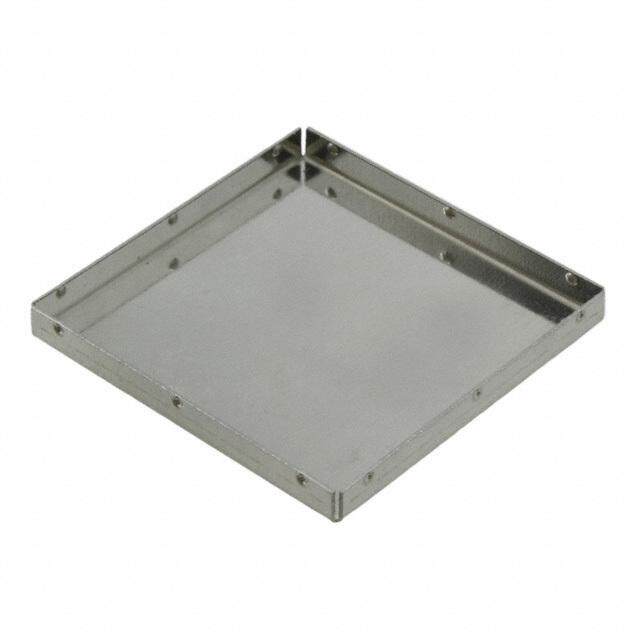
EMI ESSENTIALS BOARD LEVEL SHIELDS STANDARD DESIGN SHIELDS STANDARD SURFACE MOUNT SHIELDS — TWO-PIECE Reduce Board Damage From Inspection and Repairs Two-piece board level shields offer users the flexibility to inspect or repair shielded components without having to risk board damage by removing the entire shield or incur any tooling costs. Covers snap on and off with ease, which makes repair of the component under the shield quicker and easier and reduces board re-work. Two-piece shields are available unassembled*, and are designed to survive drop, shock and no-rattle tests. *Pre-assembly is an option. Consult sales STANDARD TWO-PIECE BOARD LEVEL SHIELDS Features and Benefits: PART OVERALL OVERALL OVERALL PARTS NUMBER LENGTH WIDTH HEIGHT PER REEL • Offers flexibility to inspect in (mm) in (mm) in (mm) or repair shield components without risking board BMI-S-201-F .538 .476 .100 1000 damage (13,66) (12,10) (2,54) • Covers snap on and off BMI-S-202-F .650 .650 .142 700 with ease (16,50) (16,50) (3,60) BMI-S-203-F 1.032 1.032 .200 300 (26,21) (26,21) (5,08) BMI-S-204-F 1.260 1.260 .236 225 (32,00) (32,00) (6,00) BMI-S-205-F 1.500 1.000 .236 250 (38,10) (25,40) (6,00) BMI-S-206-F 1.450 1.326 .200 300 (36,83) (33,68) (5,08) BMI-S-207-F 1.747 1.747 .384 120 (44,37) (44,37) (9,75) BMI-S-209-F 1.156 0.728 .275 400 (29,36) (18,50) (7,00) BMI-S-210-F 1.732 1.201 .118 370 (44,02) (30,50) (3,00) BMI-S-230-F 1.500 2.000 .200 250 (38,10) (50,80) (5,08) BMI-S-230-F-R 1.500 2.000 .200 250 (38,10) (50,80) (5,08) BMI-S-305 1.500 1.000 .236 250 (38,10) (25,40) (6,00) DESIGN PARAMETERS – ALL PART NUMBERS PICK-UP SPOT MATERIAL THICKNESS MATERIAL DIAMETER MATERIAL CARRIER TAPE 6 mm or greater 0,20 mm CRS Tin, Nickel Silver, 300 Series SS 0,20 mm LTIMS-LCB COVER TAPE MATERIAL REEL DIAMETER LTIMS-PSA 330 mm (101, 102, 103, 104, 201, 202, 203, 204) Plastic EIA-481 381 mm (105, 106, 107, 205, 206, 207) 10 www.lairdtech.com
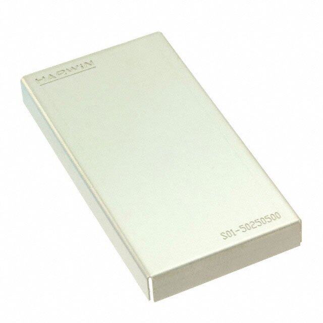
EMI ESSENTIALS BOARD LEVEL SHIELDS EZ PEEL™ PATENTED SHIELDS ARE SCORED TO ALLOW PEEL-OFF WHEN ACCESS IS NEEDED These patented shields have a solid top, scored to allow peel-off when access to board level components within the shield is required. The peel-off feature prevents damage to the board and components by eliminating the need for labor intensive de-soldering, which can often result in increased scrap. Peeling off the cover is accomplished by using a small starter hole for simple removal. This hand operation requires minimal force using a hook scriber or tweezers. Features and Benefits: After repair, replacement or adjustment of internal components, the shield can be resealed using a replacement • Easy removal of scored cover area cover. Laird offers two replacement cover options: a snap-in cover and a dish cover. • Only requires 1.5 lbs force for The snap-in cover utilizes a lance and hole design. The replacement cover snaps into place and locks into a lance cover removal feature on the frame of the original shield. • Simple replacement technique The other option is a dish cover that gets soldered into place on the board. The dish shape allows for self-location for cover of the cover for soldering. • Use on surface mount or through-hole applications EZ Peel board level shields can be packaged in tape and reel formats for easy SMT installation using conventional • Shield retains all physical pick-and-place equipment. The four standard sizes are also available without the EZ Peel (scored) feature. properties after PCMCIA/JEIDA testing for shock, bending, torque, drop and vibration • CRS 1008/1010 (tin plated) for solderability RIGID CORNER The rigid corner board-level shield incorporates a corner design that optimizes component rigidity for increased part and printed circuit board (PCB) firmness. As PCB designers are increasingly using thinner substrates, a rigid frame reinforces the assembly, thereby improving overall ruggedness and performance. The shield has improved solder joint reliability and resistance to solder joint fracture, especially in drop testing performance with thin PCBs. Several standard Laird EMI style parts including single-piece, two-piece, and multi-compartmental board-level shields use this new rigid corner design, along with availability in custom sizes as well. The rigid corner shield is stronger and more robust than traditional formed shields, which results in coplanarity improvement of the solder castellations. The shield can tolerate more deflection (i.e., more handling) without plastic deformation. Elimination of drawn flange reduces the space needed on the PCB for shielding trace width by potentially ~0.3 mm, allowing for the shield to be more closely placed on the PCB. Elimination of draft allows for more undershield space and improved component clearance. The partially drawn corner is located near the top portion the shield, resulting in improved torsional rigidity with no drawn lip and no draft. For parts over 2 mm, the corner is both drawn and formed with an interlocking multi-radius corner, which provides superior EMI shielding effectiveness. The interlocking corner can be meshed and closed in during the forming and drawing process for additional improved rigidity for parts taller than 2 mm. For parts under 2 mm, the entire corner is drawn without an interlocking corner. FEATURES MARKETS • Corner openings are reduced, • Computing improving shielding performance • Telecommunications • Partially drawn corner located near the top • Data Transfer and Information portion of the corner combined with 90° Technology straight forming of wall sections for improved • Automotive torsional rigidity. • Consumer Electronics • U.S. Patent No. 7,488,902 • Aerospace / Defense • Medical • Portability • Industrial & Instrumentation • Public Utilities 11 www.lairdtech.com
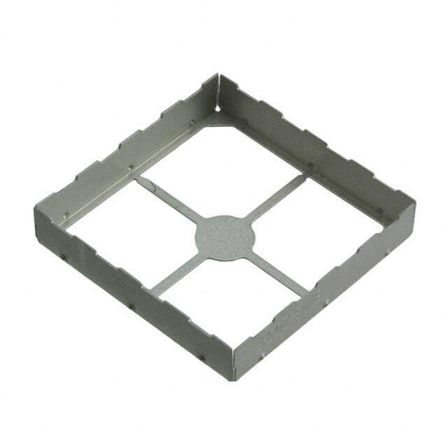
EMI ESSENTIALS BOARD LEVEL SHIELDS RECOVR™ The proprietary and patented ReCovr™ product line incorporates the functionality of a two-piece shield without the need for a separate frame and cover. The shield is specially designed with a locking mechanism that allows for easy removal of the shield cover when access to board-level components is required. The locking mechanism makes repair of components under the shield quick and easy by eliminating the need for removing the entire shield and reducing board re-work. The removable top shield also integrates Laird patented rigid corner board-level shield technology, which incorporates a new corner design that optimizes component rigidity for increased part and printed circuit board (PCB) firmness. 8 7 6 5 4 3 2 1 FEATURES MARKETS OR APPLICATIONS REV. DESCRIPTIROENVISIONS DATE APPROVED RSOEMLDOEVRA TBOL EB OLIDA RADFTER A INITAL RELEASE 06/28/2010 MF • S ingle-piece board-level shield with a removable • Computing D D top cover • Telecommunications / Datacom • Eave-less side walls when the cover is removed • Automotive 2.35 .093 4.05 5.00 TYP • SMT or through-hole pin configurations available • Consumer Electronics .159 .197 • U.S. Patent No. 7504592 8• SMART Met7ering 6 5 4 3E 2REV. DESCRIPTIROENVISIONS 1DATE APPROVED R.003.39 • Oh othlee rp achttaerrancst,e craissttiecsll atytipoincas,l ttroa coen cel-epaieracnec seh nieoldtcsh: evse,Dn ett c. •• AMeerdoiscpaalce / Defense C 5.1.092.107.7006 TYP RSOEMLDOEVRA TBOL EB OLIDA RADFTER 215..040000X A INITAL RELEASE 06/28/2010 MF D RMEACXOIMVURM SC SOHERAER L IRNEEQUIRED C 2.41 BENEFITS • Industrial & Instrumentation .095 • Eliminates need for replacement covers 4.1.0559 .51.9070 TYP .029.336 TYP 2.30.839.5310 0 SCDAELTAE I1L0 E : 1 2.0.4915 DETAIL F • Offered as an assembled product only: tape and reel, E 1.500 X R0.9 SCALE 10 : 1 B .033 B • tErxacye plleanckt ,f oorr plaeyreior dpiac ctkesting or rework applicatioCns. 5.02.10.7006 TYP 215..040000 X 6..203060 RMEACXOIMVURM SC SOHERAER L IRNEEQUIRED C F .197 X X • Limited footprint configurations (L-shapes, etc) 2 .525.401 T YP 2.200 TYP .1.00095 0.100 [.0039]ALL SURFACES .087 • Available in select Laird standard board-level sizes or .029.336 TYP 3.00D0E TTYAPIL E 3. .102.100.849015 T YP custom configurations 318..510000 A .11SC8ALE 10 : 1 NOTE: CRITICAL DIMENSIONS ARE DESIGNATED BSYCD AEXLTEA I1L0 F : 1 A B X 6..203060 X Tftnmtdroahooimo kistm3ed eds2 hepdna mols r dde3iwoodcirmnnda ess eweo.od l nn ilenfidso ngtio hrtm inaisos o sngvd dwyeer aeridnl lwld e.iam Rrirnalaweegwtfnae.e isndy3riosgd n sFCHDABmdrdcCRNeAAGloiioWDmsefE epnSIMcNt UeGAvrrlkNaeiI.cNenA MyTtnUA srAoTuesicIHNNoilOnUEodeeDnARinIr Lt ZsiaoEsn D psnno h3uclnyo BSrpeTl pywDaMls .aPo n nAaDcsRd eTIpau eSR saEprasF -eE orll1fRye oEnf No0trlCyo rE5.: UNTXXO...AI..XXXTXXLSNX XEX=:X G R =M= AU = =M N L. 4 A C.3(2 R.I.1EN10:.S0C:H)DE S P3IRGRODNJ AEECNDTG IIONLEN SOLIDWORKSMFIANTISE1HR:I.AF2LU5:B1-L510L.00 00H08% AM/ 1MRIC0DA1RT 0OTTEE NC MTSIRN PTSHEIRCK RTHPCOICHROSK NOCEONSMDS:T P)[ULR.A00OCIN.1T2TL:0 I5(LOBY0EAESDNE0S .P .0ADD0R02ORT)00AC8W]UIMNEGN TPA RDINTIS AFNBCONSULRDOMMCM SPBAEREDATORI O ITP:OLR-NI EEASCTNAO:-YR NOY23T NALT:AOEI1N0I RWLEDADI5T I TRHINEDOC TUTHHETNIC SWO HDRLNOOIMTORCTGEEOLUNOVIEDM :SGAAEEUILNME/TSSTDH. IOHISRT F ACRMEDIWOZAAANENY0TT FI ENOTBI6D:OYN E:/1T NF B2RTA EIOAOP8LMPR/MFO2 V20SEFBDI1Z B0EY: REMOVL™ X 8 7 6 5 4 3 2 1 2.550 TYP 2.200 TYP .100 0.100 [.0039]ALL SURFACES .087 3.000 TYP 3.000 TYP .118 .118 A NOTE: CRITICAL DIMENSIONS ARE DESIGNATED BY X A Ttsoehopela RlreaestMsio odnve lft oaferccahetm uwreeinl lti n aocllfoo trwhpeo f robarrt ieadsug tteoh amef atRetereC dtho dever f taraatcmthaemch iesmn seto.nltd emreedch taon tishme PaCpBp.l iEedas teoTftnmtdroah ooimo kistm3 oed eds2t hepdna molfhs r dde3iwoo dcirmnndaed ess eweo.od l nn il enfeidso ngtpio hrtm t inaisos o singavd dwyceer aeridnlc lwlkd e.iam Rrirhnalaweeugwtfnae.em isndy3rpiosgd n s ebCHDAnBmdrdcCRNerAAGloiioWDmsefE epntSiIMcNt UeGAvrrldkNaei I.cNenA MyTtnUaA srAoTuesicIHgNNoilOnUEodeeDnARlinIr Lt ZsiaoEseno D psnno h3uclny o BSnrpeTl pywDaoMls .aPo n nAaDgcsRd eTIfpau eSR saEpras F -eE orll1fRye awoEnf No0trlCyo rE5 .: iBtUhNTLXXO...AI..XXXTXXLSNX XSEX =:X G R =M=r AU = = M N L. e4 A f C.3(2 R.I.1ENr10:l.S0C:aiHa)mDbE S Ple3IRGReODN J A EEtCNDaoTG IIONLnE N SaOdLlI DlcWoOowRKnS sfMFIANoiTISEs1HR:I.AFr2LtU5: 1-Le510Le.00 00H0n8%a AM/ 1MRtIC0sDA 1RT y0OTTEE NC, MTS IRN PTSHEIRCK RTHPCOICHROSK NOCEONSMDS:T P)[ULR.A00OCIN.1T2TL:0 I5(LOBY0EAESDNE0S .P .0ADD0R02ORT)00AC8W]UIMNEGN TPA RDINTIS AFNBCONSULRDOMMCM SPBAEREDATORI O ITP:OLR-NI EEASCTNAO:-YR NOY23T NALT:AOEI1N0I RWLEDADI5T I TRHINEDOC TUTHHETNIC SWO HDRLNOOIMTORCTGEEOLUNOVIEDM :SGAAEEUILNME/TSSTDH. IOHISRT F ACRMEDIWOZAAANENY0TT FI ENOTBI6D:OYN E:/1T NF B2RTA EIOAOP8LMPR/MFO2 V20SEFBDI1Z B0EY: 8 7 6 5 4 3 2 1 FEATURES MARKETS • Detachment is permanent – cannot be replaced like • Ideal for customer manufacturing processes where ReCovr post reflow detachment of the pickup bridge is required or • Min Height: 2.0 mm (.080”) Lower heights required desired. Applications that often require the bridge to Product Development Review be detached include: • Top Flange Width: 1.8 mm (.071”) – Inspection • Flatness: Part Size Dependent, but typical to other – Rework Frame BLS parts – TIM Assembly into cover • Configurations Min 4 legs/branches required – Cover with contact fingers to chip, etc. (see BLS Style options) – Noise / Vibration concerns of bridge to cover • Limitations: Must be folded or rigid corner type BLS. (No fully drawn parts.) • Pull Force (Typ) 0.5 – 1.0 lbs Note: Due to delicate nature of the attachment of the pickup bridge, there will be some risk to the bridge separating during pick and place operations depending on customer manufacturing processes. Pick and place head depth tolerance (z axis) -.020” 12 www.lairdtech.com
EMI ESSENTIALS BOARD LEVEL SHIELDS INTRODUCTION The complexities of today's electronics pose several design challenges. Resolving EMI needs to be balanced with space, weight and production restraints. When designing a custom shielding solution, beginning in the earliest stages of the application design allows effective elimination of EMI while meeting all specifications. Laird board level shielding experts work through all phases of development. From design, rapid prototyping and pre-production through Series 97-2100 production and automated packaging, Laird has the experience to help speed a product to market and stay within budget. MULTI-COMPARTMENTAL SHIELD DESIGN To increase manufacturing throughout and reduce costs, Laird has developed SHIELD MULTIPLE CIRCUIT GROUPS SAVE PCB SPACE AND PRODUCTION a proprietary in-line production process that includes part TIME formation, wash, assembly, inspection and automated packaging. Multi-compartmental shields feature internal dividing walls of one material By integrating quality processes, board level shield quality and performance is thickness and meet all on-board shield requirements for FCC, VDE, CISPR ensured from design stage through final packaging. One process is the auto- and CE. These shields are available in two-piece designs, either assembled mated co-planarity inspection system. Laird replicates the customer application or unassembled. Our unassembled versions allow for automatic optical by measuring shields in the same plane as the printed circuit board. This is inspection prior to cover placement. As in all our shielding offerings, accomplished without "securing" or "touching" shields, which could throw Laird proprietary process for 100% automatic optical off measurement and/or deform parts. Laird measures shields immediately inspection verifies co-planarity including inner walls. prior to placement into carrier tape at speeds that match automation packing. DRAWN BOARD LEVEL SHIELDS Shield base materials include our exclusive Shield-LiteTM, CRS 1008/1010, SEAMLESS CORNERS ADDRESS HIGH-FREQUENCY LEAKAGE beryllium copper alloys, nickel-silver alloys, copper-based alloys and spring As microprocessor speeds continue to increase, so does the potential for EMI steels. All shields are fully solderable. leakage through the smallest apertures in board level shields. Laird drawn board level shields are designed to provide additional near-field and far-field circuit isolation (attenuation) at higher frequencies by eliminating the apertures found ONE-PIECE SHIELD DESIGN in the corners of traditional board level solutions. Drawn board level shields LOW COST/EXCELLENT EFFECTIVENESS utilize small ground trace sizes, thereby preserving space on the circuit board. Custom surface mount shields are available in both one-piece and • Solid corner designs when additional circuit isolation (attenuation) is two-piece designs. One-piece shields provide six sides of protection, required at higher frequencies with the sixth side being the board itself. One-piece designs offer • Available in custom heights up to .250" (6,4 mm) with length and width economical shielding alternatives where access to covered components for dimensions from .300" (7,6 mm) to 2.0" (50,8 mm) repair is not necessary. • Tape and reel packaging provides an economical and automated SMT TWO-PIECE SHIELD DESIGN attachment method QUICK, EASY REPAIR AND INSPECTION OF COVERED • Available in cold rolled steel, brass, stainless steel and nickel silver COMPONENTS • Molded Compartment Shields and Form-In-Place elastomers can be Two-piece board level shields offer users the flexibility to inspect or repair combined with drawn board level shields to achieve shielding of shielded components without having to risk board damage by removing multiple components with a single part the entire shield. Covers snap on and off with ease, making repairs quicker • Available with an EZ Peel scored cover feature; allows for easy top and easier, and reducing board re-work. Two-piece shields are available section removal for component repair and re-sealing pre-assembled or unassembled. Large locking dimples snap into slots on • Ventilation holes as needed for solder outgassing. covers to provide mechanical retention force. Smaller grounding dimples provide electrical grounding for proper shielding and to prevent rattle. • Online shielding effectiveness calculator Two-piece shields survive drop, shock and no-rattle tests. Here are critical test results: SURFACE MOUNT SHIELDS MATERIAL VARIATIONS • Able to withstand acceleration of 4g from 10 Hz to 2000 Hz for three hours in each of three planes as per SAE J1455 RAW MATERIAL* THinIC (KmNmE)SS COMMENTS • Pass EN 50 155 for railway electrical equipment including vibration test Col1d0 R0o8l/l1e0d 1S0teel 0.005 ttoo 02.,029806 )(0,127 Pre-plated Tin of 30g from 5 Hz to 200 Hz in 3 directions and a shock test with 500 m/s for 11/ms Nickel-silver alloys (00.,010042 ttoo 00.,041066 ) No psolaflodtiren rgSaM breiTlqi t uyired • Pass standard telecommunications drop tests [6 faces, dropped 1 meter onto concrete floor] Phosphor Bronze alloys (00.,010040 ttoo 00.,052100 ) Pre-tempered & Preplated Notice: The data set forth in all text, tables, charts, graphs and figures herein are based on samples tested and are *Other materials may be available, please consult sales. not guaranteed for all samples or applications. Such data are intended as guides and do not reflect product Note: Co-planarity dependant on design specification for any specific part. Material properties are for reference only. Product testing by purchaser is recommended to 13 confirm. Laird assumes no liability for product failure unless specifically stated in writing. www.lairdtech.com
EMI ESSENTIALS FINGERSTOCK PRODUCT SELECTION GUIDE Application Type Enclosure Shielding Continuous Length Std. Contact Strips Gaskets & Contact (Coil Products) Reverse Bend Strips Contact Strips Double Sided Contact Strip Twist Series Fixed Length Strips Tape Mount Fold Over Series Low Profile Low Profile with Mini-Clip On Edge Hook Clip-On Mount Symmetrical Large Enclosure Twist Std Contact Strips Contact Strips Reverse Bend Reverse Bend Contact Strips Contact Strips Double Sided Longitudinal Contact Strip Contacts All Purpose Perpendicular / S3 - Solid Top, PCB Edge Contact Symmetrical, Slotted No-Snag Track Mount Brass Track with Rivet Mount Direct to Chassis / Slot Mount Stainless Track Extrusion Mount Compact PCI - Stainless Track w/ Dot 10 Integral rivet Variable Slot Mount Internal Contact Contact Rings External Contact D-Sub Enclosure & PCB I/O's Back Plane DIN Connector Gaskets USB IEEE 1394 Fiber Optic GBIC SFP/XFP Contact / Grounding SMT 14 www.lairdtech.com
EMI ESSENTIALS FINGERSTOCK Engineered metal Fingerstock solutions from Laird dates from 1938. Laird specializes in designing miniature parts of thin strip metal in quantities ranging from thousands of pieces to millions of pieces. With over 3,400 standard parts, Laird probably already has an off-the- shelf solution that meets your application’s requirements. When custom designs are needed, Laird engineering staff helps construct efficiencies in performance, cost and manufacturability from the very beginning stages of the application. Laird specialized capabilities: • Assembly • Heat staking (both hand and automatic) • Heat treating • In-house die and fixture manufacturing • Multislide equipment • Photoetching • Plating • Progressive die stamping • Prototype fabrication • Resistance welding • Riveting • Secondary fabrication • Wire EDM 15 www.lairdtech.com
EMI ESSENTIALS FINGERSTOCK MOUNTING METHODS UNIVERSAL MOUNTING A stainless steel mounting track is available for use with our full line of gasketing materials. Its unique design offers a secure mounting option versatile enough for use with fingerstock, ElectroNit® mesh, ElectroSeal elastomers, UltraSoft® Knit and fabric-over-foam products. PART NUMBER WIDTH 0.356 X = TMHAICTKENRIEASLS (9.042) 0095-X996-00 0.310 (7.874) 0.205 0.205 0095-X997-00 0.430 (10.922) 0.145 (5.207) (5.207) 0.356 (3.683) X = TMHAICTKENRIEASLS (9.042) 0095-X998-00 0.600 (15.240) X = TMHAICTKENRIEASLS (03..164853) (09..305462) (05..220057) (05..220057) (03..164853) (05..220057) (00..041587) DETAIL “A(”05..220057) MAB A==T 00E..R00I43A50L T((10H..I17C46K32N))ESS W XX == TTMMHHAAIICCTTKKEENNRRIIEEAASSLLSS (00..041587) ((0303....161648485353)) SEED DEETATAILI L“ A“A””((0505....22220000((57570909))....303054546262)) ((0505....222200005757)) W 0.018 DETAIL “A” C = 0.060 (1.524) (0.457) SEE DETAIL “A” D = 0.090 (2.286) ((0000....040415158787)) DDEETTAAIILL ““AA”” W SEE DETAIL “A” Universal Mount E = 0.150 (3.810) 0.699 WW SSEEEE DDEETTAAIILL ““AA”” (17.755) 1.500 0.699 To identify proper mounting track, select width and (38.100) (17.755) 1.500 (107.6.79595) ((33117488..5.8.1409000809)) (38.100) cRoerprleascpeo tnhdein “gX p”a wrti tnhu rmeqbueirr efrdo mm athteer iaabl othviec kcnheasrst.. ((110077..6.6.7799559955)) (31748.8.49089) ((3311774488..8.8.4499008899)) ((331188..5.5.1100000000)) 14.898 (378.409) ^ Shielding gaskets may be mounted for either wiping or compression closing applications. Proper positioning of the shielding gasket must take into consideration the closing design and the configuration of the mounting surface. Rivet Mount Slot Mount Laird shielding devices may be mounted quickly and easily using any of several different methods. Each installation method is described in the text that follows. However, if you should run into a unique situation not resolved by any of these methods, give us a call. More than Sticky Fingers® Clip-On Mounting Tape Track Mount likely we can provide the exact answer you need. RIVET MOUNT 4. Allow 24 hours minimum curing time. Riveting produces a tight, long-lasting installation. Either plastic or metal rivets may be used. Standard parts are supplied with nonconductive tape. For rough surface applications, such as flame-sprayed surfaces, 0.010 in. (0.254 mm) thick SLOT MOUNT nonconductive tape is recommended. Optional conductive tape is also available. Slot mounted parts are easily installed using slots where bi-directional movement is required. Contact a sales department representative for additional ordering information. Simply install part into one slot and snap it into the second slot or over the edge of the frame. CLIP-ON MOUNTING ADHESIVE MOUNTING Clip-on gaskets hold firmly in place due to their own spring characteristics. Sticky Fingers® is an instant, pressure-sensitive adhesive bonding system, ideal for all-purpose Simply push the strips onto the edge or flange of the door or enclosure. contact strips for metal cabinets and electronic enclosures, and is unaffected by temperatures Also available are clip-on gaskets with either “T” or “D” lances. from -67 to +250°F (-55 to +121°C). Simply follow these four easy steps: TAPE TRACK MOUNTING 1. Remove all grease and oily residue with solvent. Smooth the mounting surface with emery Stainless Steel mounting track with PSA (pressure sensitive adhesive) is available cloth. on the Symmetrical Slotted Series and Slot Mount Series. 2. Peel off protective paper backing. WELDING 3. Place gasket in correct position. (See mounting methods diagrams A through E.) Press firmly Welded mounting requires simple, traditional welding techniques. to ensure a good adhesive bond. Avoid repositioning, which might impair the effectiveness of SOLDERING the adhesive or may bend or kink the strip. Solder mounting requires normal low temperature soldering techniques, NOTE: On items where fingers cover the solid portion of the gasket, pressure may be applied including cleaning and fluxing of parts with common copper flux materials. 16 by inserting a mandrel in the strip and pressing down. For contact strips with Magnefil® insert, simply press down on the fingers. www.lairdtech.com
EMI ESSENTIALS FINGERSTOCK ORDERING INFORMATION Part Number Format Example: Stock Item Unique Part No. Finish I.D. 0 0 9 7 — 0 5 2 0 — 0 2 • In the above example, Laird part number 0097-0520-02 is a 0.00005 in. (0.0013 mm) min.] but can be varied to meet 97-520 RFI/EMI shielding gasket with a bright finish your custom needs • When ordering UltraSoft® items, the stock item prefix will • Modifications to standard parts are specified by an X be 0098 or 0078. The above example in UltraSoft would be (following finish I.D.) for quoting only. Upon ordering, 0098-0520-02. a specific part number will be assigned. • When ordering coil, the prefix 0C should precede the stock • For tape options, see Adhesive Mounting — Sticky Fingers® item number; for example: 0C97, 0C98, 0C77 or 0C78 on page 16 • When ordering stainless steel items, the stock item prefix will • Use the catalog number for the unique part number and refer be 0095 to the following chart for finish I.D. • Standard plating finish is 0.0001 in. (0.0025 mm) min. [gold Plating Finishes Finish Designation Finishes for Fingerstock Products Laird Specifications Specification Details* (BeCu and RCC) ID Unplated Bright Finish 02 Laird Designation Unplated, Bright or Ultrasoft surface Solderable Unplated 21 Laird Designation Solderable bright finish Gold Gold 03 ASTM B 488 / SAE AMS 2422 Type I & II, grade C, 1.27 - 2.5 µm thick Gold/Nickel Underplate 10 ASTM B 488 / SAE AMS 2403 Type I & II, grade C, 1.27 - 2.5 µm thick Silver Silver (matte) 04 ASTM B 700 / QQ-S-305 Type II, grade A, 2.5 - 7.6 µm thick Cadmium** Cadmium + Yellow Chromate 05 ASTM B 766 / AMS QQ P 416 Type II, class 5, min 5 µm thick Cadmium + Clear Chromate 06 ASTM B 766 / AMS QQ P 416 Type III, class 5, min 5 µm thick Tin Lead** Tin Lead [60/40] Solder 07 ASTM B 579 / SAE AMS P 81728 7.6 - 12.7 µm thick Nickel Dull Nickel 09 ASTM B 689 / SAE AMS 2403 (QQ-N-290) 2.5 - 7.6 µm thick* Bright Nickel 19 ASTM B 689 / SAE AMS 2403 (QQ-N-290) 2.5 - 7.6 µm thick* Sulfamate Nickel 24 ASTM B 689 / SAE AMS 2424 2.5 - 7.6 µm thick (1.27 - 2.5 µm underplate) Electroless Nickel Electroless Nickel 18 ASTM B 733 / SAE AMS C 26074 2.5 - 7.6 µm thick Tin Satin / Matte Tin 08 ASTM B 545 / MIL-T-10727C Type I, 2.5 - 7.6 µm thick Bright Tin 17 ASTM B 545 / MIL-T-10727C Type I, 2.5 - 7.6 µm thick Zinc*** Zinc + Yellow Chromate 16 SAE AMS 2402 / ASTM B 633 Type II, 2.5 - 7.6 µm thick Zinc + Clear Chromate 15 SAE AMS 2402 / ASTM B 633 Type III, 2.5 - 7.6 µm thick Notes: - Laird standard plating codes are defined according to the above specifications. Any non-standard requirements (different classes or types within a specification) must be clearly identified on the production prints. - The plating thickness indicates the thickness measured on the primary out-surface of fingerstock products. * Class 1, Grade G in QQ-N-290 ** Outsourced process *** Laird provides RoHS compliant Trivalent Chromate 17 www.lairdtech.com
EMI ESSENTIALS FINGERSTOCK ULTRASOFT® SERIES Series UltraSoft® fingers have been designed for communications, computers and electronic systems designers concerned with EMI compliance and lightweight enclosure designs. Available in the same full range of standard configurations, UltraSoft fingers offer designers greater flexibility and versatility than ever before—permitting more extensive use of lighteFr,O tLhDiOnVnEeRr S cERoInESstruction materials Standard No.97-541 to help cut costs and/or enhance system performance. UltraSoft No.98-541 The unique advantages of UltraSoft (98-Series) fingers include: • The lowest compression forces in the industry 160 140 • Shielding effectiveness comparable to similarly configured standard 97-Series parts 120 •• WLoiwde c soemlepcrteiosnsi oonf sfoizrecse avnedrs icoonn fiagvauirlaatbiolen sfo r virtually every standard Attenuation (dB)shie1860l000ding product UltraSoft (98-Series) products are available in the same lengths as the stand40ard (97-Series) products. Please refer to the appropriate 20 standard product pages for specific information. All UltraSoft products are also available in your choice of finishes. 0 10K 100K 1M 10M 100M 1G Frequency (Hz) Shielding Effectiveness Comparison Compression Force Comparison Standard No.97-541 FOLDOVER SERIES UltraSoft No.98-541 Standard No.97-541 UltraSoft No.98-541 Height (Millimeters) 1.500 2.000 2.500 3.000 100 140 160 90 140 80 120 Attenuation (dB) 118642000000 Load (Lbs./linear ft.) 7654300000 186400000 Load (Kg/linear m) 20 20 20 0 10 10K 100K 1M Frequency (H1z)0M 100M 1G 0 0 0.040 0.050 0.060 0.070 0.080 0.090 0.100 0.110 0.120 Height (Inches) Standard No.97-541 RECYCLABUltraLSoft ENo.9 8-C541 LEAN COPPER™ Height (Millimeters) 1.500 2.000 2.500 3.000 100 140 Recyc90lable Clean Copper products meld The product is targeted at high stron8g0 stability and tensile strength volume desig1n20s. Custom stampings Recyclable Clean Copper (RCC) beryllium- wefsLoad (Lbs./linear ft.)ohleirit echutl d76543rth00000iiiclinigazghal t calioeopnvnped liilucnsac obttiifovo ttinthhyse gmramrtoa aaukl ni cnadognisn dtitg t shauanittd ai sb le aAfiCrnose gp waepirvetsahrt io liaascl bklc l ooegmf a1864 u0000Lsp0pakloLoad (Kg/linear m)eiernttdes ,clm yuR esflettcaoaymmlc leeaprb rlroeeo qCfu.leeastn. feaarxlpelcopeeyl ilEscle Ma(nBtIit eo saCnhlustie.e) Tl rdinhniaen at gci v wooenif dftveoeer rsbrsa eiconrunygsl etloio ufom mfp ea scrlrosot tnanttenuad min binegr comp20arable with traditional metal EMI (Stock Item) of BeCu to RCC: For mounting2 0methods and other spe- shield10s. Shielding effectiveness is similar to oth0er copper alloys with values over cific product i0nformation, please BeCu RCC 0.040 0.050 0.060 0.070 0.080 0.090 0.100 s e e 0 .1L10a i r d 0 .1c20atalog 100 dB shielding effectiveneHsesig hrt e(Inacheds)ily 0077- 0067- “Fingerstock, Gaskets and Metal achieved. Grounding Products”. 0c77- 0c67- Recyclable Clean Copper is fully To find out more about this exciting 0097- 0087- compliant to EU Directive 2002/95/EC new product available from Laird please 0c97- 0c87- and alleviates the environmental, safety contact sales for assistance or visit us at and segregation concerns associated 0078- 0068- www.lairdtech.com. with the traditional use and recycling 0c78- 0c68- of beryllium-based copper alloys. 0098- 0088- This alternative material exhibits 0c98- 0c88- excellent corrosion resistance, platability, solderability and stress 18 relaxation properties. www.lairdtech.com
EMI ESSENTIALS FINGERSTOCK SLOT MOUNT SERIES Laird Slot Mount Series of beryllium copper shielding gaskets is designed for use in a wide variety of slotted applications. This economical product line is ideal for both grounding and shielding applications. • Minimal slot fabrication cost • Easy and cost-effective installation since fasteners and adhesives are not 77-011 required 77-011 • Bi-directional wiping and compression action to accommodate a wide variety of designs • Ideal for grounding and shielding in the following electronic enclosure 77-015 applications: 77-015 – Front panel handles – Chassis covers 77-018 77-010 – Plug-in units – Backplanes 77-018 77-010 – Subrack assemblies • Standard (77-Series) and UltraSoft® (78-Series low compression versions) are also supplied in 25.0 ft. (7.6 m) coils The Slot Mount Series is available in your choice of finishes, see page 17. TOP VIEW TOP VIEW *N *N *O A *O A E D PitchD Pitch SlEot Slot T*hPMickanteers*isaPl Ltheen gntuhm Ltohebfene s grnl otouhtfm iofsbi fnde sgerl eoportefs n i fsudi nsdeegendeptr eosn nudseendt on Approx.Length Material Thickness Approx.Length forS deiem peangseio 2n-s2. Recommended Mounting Hole Pattern forS deiem peangseio 2n-s2. forS deiem peangseio 2n-s2. Recommended Mounting Hole Pattern forS deiem peangseio 2n-s2. RIGHT VIEW RIGHT VIEW B B H H M M C C See page 2-2 Q Radius (R) See page 2-2 for dimensions. for dimensions. See page 2-2 Q Radius (R) See page 2-2 for dimensions. for dimensions. Slot Mount Series are available with Universal and Tape Track mounting Slot Mopotuionnt sS,esreiees p aargee a 1va-9il,a1bl-e1 0w.ith Universal and Tape Track mounting options,see page 1-9,1-10. 19 www.lairdtech.com
EMI ESSENTIALS FINGERSTOCK SLOT MOUNT SERIES SERIES A B C DE H M *N *O *P Q LENGTH # OF SERIES A B C DE H M *N *O *P Q LENGTH # OF SLOT MOUNT SERIES DIMENSIONS RECOMMENDED (R) APPROX. FING. RECOMMENDED (R) APPROX. FING. 77-010 0.320 0.110 0.004 0.187 0.018 0.085 0.110 0.090 0.260 0.040 0.020 16.000 86 77-045 0.320 0.110 0.004 N/A N/A 0.085 0.110 0.090 0.260 0.060 0.040 0.169 1 (8.128) (2.794)(0.102)(4.750)(0.457)(2.159)(2.794)(2.286) (6.604)(1.016) (0.508) (406.400) — (8.128) (2.794)(0.102) — — (2.159)(2.794)(2.286) (6.604)(1.524) (1.016) (4.293) — SERIES A B C DE H M *N *O *P Q LENGTH # OF SERIES A B C DE H M *N *O *P Q LENGTH # OF RECOMMENDED (R) APPROX. FING. 77-011 0.600 0.220RE0C.0O0M5ME0N.2D8E2D0.032(R)0.140APP0R.O18X0. FI0N.1G4.0 0.520 0.070 0.040 16.000 57 77-046 0.320 0.110 0.004 0.187 0.018 0.085 0.110 0.090 0.260 0.060 0.040 0.356 2 77-010 0.320 0.110 0.004 0.187 0.018 0.085 0.110 0.090 0.260 0.040 0.020 16.000 86 77-045 0.320 0.110 0.004 N/A N/A 0.08(155.204.01)1(05.5808.0)9(00.1207.2)6(07.1603.0)6(00.8103.)04(30.556)0.(146.5972)(31.556)(13.208)(1.778) (1.016) (406.400) — (8.128) (2.794)(0.102)(4.750)(0.457)(2.159)(2.794)(2.286) (6.604)(1.524) (1.016) (9.042) — (8.128) (2.794)(0.102)(4.750)(0.457)(2.159)(2.794)(2.286) (6.604)(1.016) (0.508) (406.400) — (8.128) (2.794)(0.102) — —77-0(21.51 5 90).6(20.07940).2(22.02860).0(065.604)N/(A1.524N)/(A1.0106.)140(4.209.138)0 —0.140 0.520 0.070 0.040 0.250 1 77-047 0.320 0.110 0.004 0.187 0.018 0.085 0.110 0.090 0.260 0.060 0.040 0.543 3 77-011 0.600 0.220 0.005 0.282 0.032 0.140 0.180 0.140 0.520 0.070 0.040 16.000 57 77-046 0.320 0.110 0.004 0.187 0.018 0.0(8155.2400.1)1(05.5808.)09(00.1207.)260—0.060—0.0(34.0556)0(4.3.55672)(3.2556)(13.208)(1.778) (1.016) (6.350) — (8.128) (2.794)(0.102)(4.750)(0.457)(2.159)(2.794)(2.286) (6604) (1.524) (1.016) (13.792) — (15.240)(5.588)(0.127)(7.163)(0.813)(3.556)(4.572)(3.556)(13.208)(1.778) (1.016) (406.400) — (8.128) (2.794)(0.102)(4.750)(0.45777)-0(126.1 590).32(20.7940).1(120.2860).00(64.604N)/A(1.524N)/A(1.0106.0)85(9.00.4121)0 0—.090 0.260 0.040 0.020 0.169 1 77-048 0.320 0.110 0.004 0.187 0.018 0.085 0.110 0.090 0.260 0.060 0.040 0.730 4 77-015 0.600 0.220 0.005 N/A N/A 0.140 0.180 0.140 0.520 0.070 0.040 0.250 1 77-047 0.320 0.110 0.004 0.187 0.018 0.08(85.1208.)11(02.7904.)09(00.1002.)260—0.060—0.0(24.0159)0(2.5.74934)(2.3286) (6.604)(1.016) (0.508) (4.293) — (8.128) (2.794)(0.102)(4.750)(0.457)(2.159)(2.794)(2.286) (6.604)(1.524) (1.016) (18.542) — (15.240)(5.588)(0.127) — — (3.556)(4.572)(3.556)(13.208)(1.778) (1.016) (6.350) — (8.128) (2.794)(0.102)(4.750)(0.45777)-0(127.1 590).32(20.7940).1(120.2860).00(646040).18(17.5204.)01(18.0106.)085(13.07.9121)0 —0.090 0.260 0.040 0.020 0.356 2 77-050 0.320 0.110 0.004 0.187 0.018 0.085 0.110 0.090 0.260 0.060 0.040 0.917 5 77-016 0.320 0.110 0.004 N/A N/A 0.085 0.110 0.090 0.260 0.040 0.020 0.169 1 77-048 0.320 0.110 0.004 0.187 0.018 0.08(85.1208.)11(02.7904.)09(00.1002.)26(40.7500.)06(00.4570).0(420.159)0(.273.7094)(24.286) (6.604)(1.016) (0.508) (9.042) — (8.128) (2.794)(0.102)(4.750)(0.457)(2.159)(2.794)(2.286) (6.604)(1.524) (1.016) (23.292) — (8.128) (2.794)(0.102) — — (2.159)(2.794)(2.286) (6.604)(1.016) (0.508) (4.293) — (8.128) (2.794)(0.102)(4.750)(0.45777)-0(128.1 590).32(20.7940).1(120.2860).00(64.6040).18(17.5204.)01(18.0106.)085(18.05.4121)0 —0.090 0.260 0.040 0.020 0.543 3 77-051 0.320 0.110 0.004 0.187 0.018 0.085 0.110 0.090 0.260 0.060 0.040 1.104 6 77-017 0.320 0.110 0.004 0.187 0.018 0.085 0.110 0.090 0.260 0.040 0.020 0.356 2 77-050 0.320 0.110 0.004 0.187 0.018 0.08(85.1208.)11(02.7904.)09(00.1002.)26(40.7500.)06(00.4570).0(420.159)0(.291.7794)(25.286) (6.604)(1.016) (0.508) (13.792) — (8.128) (2.794)(0.102)(4.750)(0.457)(2.159)(2.794)(2.286) (6.604)(1.524) (1.016) (28.042) — (8.128) (2.794)(0.102)(4.750)(0.457)(2.159)(2.794)(2.286) (6.604)(1.016) (0.508) (9.042) — (8.128) (2.794)(0.102)(4.750)(0.45777)-0(129.1 590).32(20.7940).1(120.2860).00(64.6040).18(17.5204.)01(18.0106.)085(23.02.9121)0 —0.090 0.260 0.040 0.020 0.730 4 77-052 0.320 0.110 0.004 0.187 0.018 0.085 0.110 0.090 0.260 0.060 0.040 1.291 7 77-018 0.320 0.110 0.004 0.187 0.018 0.085 0.110 0.090 0.260 0.040 0.020 0.543 3 77-051 0.320 0.110 0.004 0.187 0.018 0.08(85.1208.)11(02.7904.)09(00.1002.)26(40.7500.)06(00.4570).0(420.159)1(.210.7494)(26.286) (6.604)(1.016) (0.508) (18.542) — (8.128) (2.794)(0.102)(4.750)(0.457)(2.159)(2.794)(2.286) (6.604)(1.524) (1.016) (32.791) — (8.128) (2.794)(0.102)(4.750)(0.457)(2.159)(2.794)(2.286) (6.604)(1.016) (0.508) (13.792) — (8.128) (2.794)(0.102)(4.750)(0.45777)-0(220.1 590).60(20.7940).2(220.2860).00(65.6040).28(12.5204.)03(12.0106.)140(28.00.4128)0 —0.140 0.520 0.070 0.040 0.532 2 77-053 0.320 0.110 0.004 0.187 0.018 0.085 0.110 0.090 0.260 0.060 0.040 1.478 8 77-019 0.320 0.110 0.004 0.187 0.018 0.085 0.110 0.090 0.260 0.040 0.020 0.730 4 77-052 0.320 0.110 0.004 0.187 0.018 0.0(8155.2400.1)1(05.5808.)09(00.1207.)26(70.1603.)06(00.8130.)0(430.556)1.(249.5172)(37.556)(13.208)(1.778) (1.016) (13.513) — (8.128) (2.794)(0.102)(4.750)(0.457)(2.159)(2.794)(2.286) (6.604)(1.524) (1.016) (37.541) — (8.128) (2.794)(0.102)(4.750)(0.457)(2.159)(2.794)(2.286) (6.604)(1.016) (0.508) (18.542) — (8.128) (2.794)(0.102)(4.750)(0.45777)-0(221.1 590).32(20.7940).1(120.2860).00(64.6040).18(17.5204.)01(18.0106.)085(32.07.9111)0 —0.090 0.260 0.060 0.035 16.000 86 77-054 0.320 0.110 0.004 0.187 0.018 0.085 0.110 0.090 0.260 0.060 0.040 1.665 9 77-020 0.600 0.220 0.005 0.282 0.032 0.140 0.180 0.140 0.520 0.070 0.040 0.532 2 77-053 0.320 0.110 0.004 0.187 0.018 0.08(85.1208.)11(02.7904.)09(00.1002.)26(40.7500.)06(00.4570).0(420.159)1(.247.7894)(28.286) (6.604)(1.524) (0.889) (406.400) — (8.128) (2.794)(0.102)(4.750)(0.457)(2.159)(2.794)(2.286) (6.604)(1.524) (1.016) (42.291) — (15.240)(5.588)(0.127)(7.163)(0.813)(3.556)(4.572)(3.556)(13.208)(1.778) (1.016) (13.513) — (8.128) (2.794)(0.102)(4.750)(0.45777)-0(223.1 590).37(20.7940).1(320.2860).00(64.604N)/A(1.524N)/A(1.0106.0)85(370.5.14110) 0—.090 0.300 0.040 0.020 0.225 1 77-055 0.320 0.110 0.004 0.187 0.018 0.085 0.110 0.090 0.260 0.060 0.040 1.852 10 77-021 0.320 0.110 0.004 0.187 0.018 0.085 0.110 0.090 0.260 0.060 0.035 16.000 86 77-054 0.320 0.110 0.004 0.187 0.018 0.08(95.3908.)11(03.3002.)09(00.1002.)260—0.060—0.0(24.0159)1(2.6.76954)(2.9286) (7.620)(1.016) (0.508) (5.715) — (8.128) (2.794)(0.102)(4.750)(0.457)(2.159)(2.794)(2.286) (6.604)(1.524) (1.016) (47.041) — (8.128) (2.794)(0.102)(4.750)(0.457)(2.159)(2.794)(2.286) (6.604)(1.524) (0.889) (406.400) — (8.128) (2.794)(0.102)(4.750)(0.45777)-0(224.1 590).37(20.7940).1(320.2860).00(64.6040).25(10.5204.)02(15.0106.)085(42.02.9111)0 —0.090 0.300 0.040 0.020 0.475 2 77-058 0.320 0.110 0.004 0.187 0.018 0.085 0.110 0.090 0.260 0.040 0.020 0.917 5 77-023 0.370 0.130 0.004 N/A N/A 0.085 0.110 0.090 0.300 0.040 0.020 0.225 1 77-055 0.320 0.110 0.004 0.187 0.018 0.08(95.3908.)11(03.3002.)09(00.1002.)26(60.3500.)06(00.6350).0(420.159)1(.285.7294)(21.0286) (7.620)(1.016) (0.508) (12.065) — (8.128)(2.794)(0.102)(4.750)(0.457)(2.159)(2.794)(2.286) (6.604)(1.016)(0.508) (23.292) — (9.398) (3.302)(0.102) — — (2.159)(2.794)(2.286) (7.620)(1.016) (0.508) (5.715) — (8.128) (2.794)(0.102)(4.750)(0.45777)-0(225.1 590).37(20.7940).1(320.2860).00(64.6040).25(10.5204.)02(15.0106.)085(47.00.4111)0 —0.090 0.300 0.040 0.020 0.725 3 77-059 0.370 0.130 0.004 0.250 0.025 0.085 0.110 0.090 0.310 0.040 0.020 16.000 64 77-024 0.370 0.130 0.004 0.250 0.025 0.085 0.110 0.090 0.300 0.040 0.020 0.475 2 77-058 0.320 0.110 0.004 0.187 0.018 0.08(59.3908.)11(03.3002.)09(00.1002.)26(60.3500.)04(00.6305.)0(220.159)0.(921.7794)(25.286) (7.620)(1.016) (0.508) (18.415) — (9.398)(3.302)(0.102)(6.350)(0.635)(2.159)(2.794)(2.286) (7.874)(1.016)(0.508) (406.400) — (9.398) (3.302)(0.102)(6.350)(0.635)(2.159)(2.794)(2.286) (7.620)(1.016) (0.508) (12.065) — (8.128)(2.794)(0.102)(4.750)(0.45777)-0(226.1 590).3(720.7940).1(320.2860).0(065.6040).2(510.0160.)02(05.5008.)085(23.02.9121)0 —0.090 0.300 0.040 0.020 0.975 4 77-062 0.320 0.110 0.004 0.187 0.018 0.085 0.110 0.090 0.260 0.048 0.025 0.169 1 77-025 0.370 0.130 0.004 0.250 0.025 0.085 0.110 0.090 0.300 0.040 0.020 0.725 3 77-059 0.370 0.130 0.004 0.250 0.025 0.08(59.3908.)11(03.3002.)09(00.1207.)31(60.3500.)04(00.6305.)0(220.159)16(.20.07094)(26.4286) (7.620)(1.016) (0.508) (24.765) — (8.128) (2.794)(0.102)(4.750)(0.457)(2.159)(2.794)(2.286) (6.604)(1.219) (0.635) (4.293) — (9.398) (3.302)(0.102)(6.350)(0.635)(2.159)(2.794)(2.286) (7.620)(1.016) (0.508) (18.415) — (9.398)(3.302)(0.102)(6.350)(0.63757)-0(227.1 590).3(720.7940).1(320.2860).0(075.8740).2(510.0160.)02(05.5008.)08(54060.4.10100) —0.090 0.300 0.040 0.020 1.225 5 77-063 0.320 0.110 0.004 0.187 0.018 0.085 0.110 0.090 0.260 0.048 0.025 0.356 2 77-026 0.370 0.130 0.005 0.250 0.025 0.085 0.110 0.090 0.300 0.040 0.020 0.975 4 77-062 0.320 0.110 0.004 0.187 0.018 0.08(95.3908.)11(03.3002.)09(00.1207.)26(60.3500.)04(08.6350).0(225.159)0(.216.7994)(21.286) (7.620)(1.016) (0.508) (31.115) — (8.128) (2.794)(0.102)(4.750)(0.457)(2.159)(2.794)(2.286) (6.604)(1.219) (0.635) (9.042) — (9.398) (3.302)(0.127)(6.350)(0.635)(2.159)(2.794)(2.286) (7.620)(1.016) (0.508) (24.765) — (8.128) (2.794)(0.102)(4.750)(0.45777)-0(228.1 590).37(20.7940).1(320.2860).00(65.6040).25(10.2109.)02(05.6305.)085(4.209.131)0 —0.090 0.300 0.040 0.020 1.475 6 77-064 0.320 0.110 0.004 0.187 0.018 0.085 0.110 0.090 0.260 0.048 0.025 0.543 3 77-027 0.370 0.130 0.005 0.250 0.025 0.085 0.110 0.090 0.300 0.040 0.020 1.225 5 77-063 0.320 0.110 0.004 0.187 0.018 0.08(95.3908.)11(03.3002.)09(00.1207.)26(60.3500.)04(08.6350).0(225.159)0(.235.7694)(22.286) (7.620)(1.016) (0.508) (37.465) — (8.128) (2.794)(0.102)(4.750)(0.457)(2.159)(2.794)(2.286) (6.604)(1.219) (0.635) (13.792) — (9.398) (3.302)(0.127)(6.350)(0.635)(2.159)(2.794)(2.286) (7.620)(1.016) (0.508) (31.115) — (8.128) (2.794)(0.102)(4.750)(0.45777)-0(229.1 590).80(20.7940).3(220.2860).00(64.604N)/A(1.219N)/A(0.6305.2)00(9.00.4128)0 0—.220 0.720 0.070 0.040 0.343 1 77-065 0.320 0.110 0.004 0.187 0.018 0.085 0.110 0.090 0.260 0.048 0.025 0.730 4 77-028 0.370 0.130 0.005 0.250 0.025 0.085 0.110 0.090 0.300 0.040 0.020 1.475 6 77-064 0.320 0.110 0.004 0.187 0.018 0.0(8250.3200.1)1(08.1208.)09(00.1002.)260—0.048—0.0(52.5080)0(4.5.45372)(5.3588)(18.288)(1.778) (1.016) (8.712) — (8.128) (2.794)(0.102)(4.750)(0.457)(2.159)(2.794)(2.286) (6.604)(1.219) (0.635) (18.542) — (9.398) (3.302)(0.127)(6.350)(0.635)(2.159)(2.794)(2.286) (7.620)(1.016) (0.508) (37.465) — (8.128) (2.794)(0.102)(4.750)(0.45777)-0(320.1 590).80(20.7940).3(220.2860).00(64.6040).37(15.2109.)03(02.6305.)200(13.07.9128)0 —0.220 0.720 0.070 0.040 0.718 2 77-070 0.320 0.110 0.004 0.187 0.018 0.085 0.110 0.090 0.260 0.062 0.035 16.000 86 77-029 0.800 0.320 0.004 N/A N/A 0.200 0.180 0.220 0.720 0.070 0.040 0.343 1 77-065 0.320 0.110 0.004 0.187 0.018 0.0(8250.3200.1)1(08.1208.)09(00.1002.)26(90.5205.)04(08.8130.)0(255.080)0.(743.5072)(54.588)(18.288)(1.778) (1.016) (18.237) — (8.128) (2.794)(0.102)(4.750)(0.457)(2.159)(2.794)(2.286) (6.604)(1.575) (0.889) (406.400) — (20.320)(8.128)(0.102) — — (5.080)(4.572)(5.588)(18.288)(1.778) (1.016) (8.712) — (8.128) (2.794)(0.102)(4.750)(0.45777)-0(321.1 590).80(20.7940).3(220.2860).00(65.6040).37(15.2109.)03(02.6305.)200(18.05.4128)0 —0.220 0.720 0.070 0.040 1.093 3 77-076 0.600 0.220 0.005 N/A N/A 0.140 0.180 0.140 0.520 0.070 0.020 0.340 1 77-030 0.800 0.320 0.004 0.375 0.032 0.200 0.180 0.220 0.720 0.070 0.040 0.718 2 77-070 0.320 0.110 0.004 0.187 0.018 0.0(8250.3200.1)1(08.1208.)09(00.1207.)26(90.5205.)06(02.8130.)0(355.080)16(.40.05072)(58.6588)(18.288)(1.778) (1.016) (27.762) — (15.240)(5.588)(0.127) — — (3.556)(4.572)(3.556)(13.208)(1.778) (0.508) (8.636) — (20.320)(8.128)(0.102)(9.525)(0.813)(5.080)(4.572)(5.588)(18.288)(1.778) (1.016) (18.237) — (8.128) (2.794)(0.102)(4.750)(0.45777)-0(322.1 590).80(20.7940).3(220.2860).00(65.6040).37(15.5705.)03(02.8809.)20(04060.4.10800) —0.220 0.720 0.070 0.040 1.468 4 77-087 0.563 0.110 0.003 0.187 0.018 0.085 0.110 0.090 0.260 0.040 0.020 1.291 7 77-031 0.800 0.320 0.005 0.375 0.032 0.200 0.180 0.220 0.720 0.070 0.040 1.093 3 77-076 0.600 0.220 0.005 N/A N/A 0.14(200.302.01)8(08.1208.1)4(00.1207.5)2(09.5205.0)7(00.8103.)02(50.080)0.(344.5072)(51.588)(18.288)(1.778) (1.016) (37.287) — (14.300)(2.794)(0.076)(4.750)(0.457)(2.159)(2.794)(2.286) (6.604)(1.016) (0.508) (32.791) — (20.320)(8.128)(0.127)(9.525)(0.813)(5.080)(4.572)(5.588)(18.288)(1.778) (1.016) (27.762) — (15.240)(5.588)(0.127) — —77-0(33.55 5 60).3(140.5720).1(32.05560).0(1033.2080.)2(510.7780).0(200.5080.)090(8.603.61)15 —0.095 0.250 0.040 0.015 0.480 2 77-088 0.563 0.110 0.003 0.187 0.018 0.085 0.110 0.090 0.260 0.040 0.020 1.478 8 77-032 0.800 0.320 0.005 0.375 0.032 0.200 0.180 0.220 0.720 0.070 0.040 1.468 4 77-087 0.563 0.110 0.003 0.187 0.018 0.08(57.8704.)11(03.0408.)09(00.0706.)26(60.3500.)04(00.5008.)0(220.286)1.(229.9121)(27.413) (6.350)(1.016) (0.381) (12.192) — (14.300)(2.794)(0.076)(4.750)(0.457)(2.159)(2.794)(2.286) (6.604)(1.016) (0.508) (37.541) — (20.320)(8.128)(0.127)(9.525)(0.813)(5.080)(4.572)(5.588)(18.288)(1.778) (1.016) (37.287) — (14.300)(2.794)(0.076)(4.750)(0.45777)-0(326.1 590).31(20.7940).1(220.2860).00(63.6004.)25(10.0106.)02(00.5008.)090(32.07.9111)5 —0.095 0.250 0.040 0.015 0.980 4 77-089 0.600 0.220 0.005 0.282 0.032 0.140 0.180 0.140 0.520 0.070 0.040 0.810 3 77-035 0.310 0.120 0.003 0.250 0.020 0.090 0.115 0.095 0.250 0.040 0.015 0.480 2 77-088 0.563 0.110 0.003 0.187 0.018 0.08(57.8704.)11(03.0408.)09(00.0706.)26(60.3500.)04(00.5008.)0(220.286)1.(427.9821)(28.413) (6.350)(1.016) (0.381) (24.892) — (15.240)(5.588)(0.127)(7.163)(0.813)(3.556)(4.572)(3.556)(13.208)(1.778) (1.016) (20.574) — (7.874) (3.048)(0.076)(6.350)(0.508)(2.286)(2.921)(2.413) (6.350)(1.016) (0.381) (12.192) — (14.300)(2.794)(0.076)(4.750)(0.45777)-0(327.1 590).31(20.7940).1(220.2860).00(63.6004.)25(10.0106.)02(00.5008.)090(37.05.4111)5 —0.095 0.250 0.040 0.015 1.480 6 77-094 0.358 0.128 0.003 0.202 0.018 0.110 0.100 0.115 0.300 0.030 0.030 0.389 2 77-036 0.310 0.120 0.003 0.250 0.020 0.090 0.115 0.095 0.250 0.040 0.015 0.980 4 77-089 0.600 0.220 0.005 0.282 0.032 0.14(70.8704.)18(03.0408.)14(00.0706.)52(60.3500.)07(00.5080).0(420.286)0(.281.9021)(23.413) (6.350)(1.016) (0.381) (37.592) — (9.093) (3.251)(0.076)(5.131)(0.457)(2.794) (2.54) (2.921) (7.620)(0.762) (0.762) (9.881) — (7.874) (3.048)(0.076)(6.350)(0.508)(2.286)(2.921)(2.413) (6.350)(1.016) (0.381) (24.892) — (15.240)(5.588)(0.127)(7.163)(0.81737)-0(338.5 560).31(40.5720).1(230.5560).0(0133.2008.2)5(10.7708.)02(10.0106.0)90(20.05.7141)5 0—.095 0.250 0.040 0.015 1.980 8 77-096 0.600 0.220 0.005 0.282 0.032 0.140 0.180 0.095 0.520 0.040 0.040 1.096 4 77-037 0.310 0.120 0.003 0.250 0.020 0.090 0.115 0.095 0.250 0.040 0.015 1.480 6 77-094 0.358 0.128 0.003 0.202 0.018 0.11(07.8704.)10(03.0408.)11(50.0706.)30(60.3500.)03(00.5008.)0(320.286)0.(328.9921)(22.413) (6.350)(1.016) (0.381) (50.292) — (15.240)(5.588)(0.127)(7.163)(0.813)(3.556)(4.572)(2.413)(13.208)(1.016) (1.016) (27.838) — (7.874) (3.048)(0.076)(6.350)(0.508)(2.286)(2.921)(2.413) (6.350)(1.016) (0.381) (37.592) — (9.093) (3.251)(0.076)(5.131)(0.45777)-0(329.7 940).28(20.540).1(120.9210).00(72.620N)/A(0.762N)/A(0.7602.0)75(9.08.8111)0 0—.090 0.220 0.040 0.030 0.169 1 77-097 0.600 0.220 0.005 0.375 0.032 0.140 0.180 0.140 0.520 0.070 0.040 16.000 43 77-038 0.310 0.120 0.003 0.250 0.020 0.090 0.115 0.095 0.250 0.040 0.015 1.980 8 77-096 0.600 0.220 0.005 0.282 0.032 0.14(07.1102.)18(02.7904.)09(50.0501.)520—0.040—0.0(14.0905)1(.20.97694)(2.4286) (5.588)(1.016) (0.762) (4.293) — (15.240)(5.588)(0.127)(9.525)(0.813)(3.556)(4.572)(3.556)(13.208)(1.778) (1.016) (406.400) — (7.874) (3.048)(0.076)(6.350)(0.508)(2.286)(2.921)(2.413) (6.350)(1.016) (0.381) (50.292) — (15.240)(5.588)(0.127)(7.163)(0.81737)-0(430.5 560).28(40.5720).1(120.4130).0(0123.2008.1)8(17.0106.)01(18.0106.0)75(27.08.3181)0 0—.090 0.220 0.040 0.030 0.356 2 77-099 0.600 0.220 0.005 0.282 0.032 0.140 0.180 0.140 0.520 0.070 0.040 1.378 5 77-039 0.280 0.110 0.002 N/A N/A 0.075 0.110 0.090 0.220 0.040 0.030 0.169 1 77-097 0.600 0.220 0.005 0.375 0.032 0.14(07.1102.)18(02.7904.)14(00.0501.)52(40.7500.)07(00.4507.)0(410.905)16(.20.07094)(24.3286) (5.588)(1.016) (0.762) (9.042) — (15.240)(5.588)(0.127)(7.163)(0.813)(3.556)(4.572)(3.556)(13.208)(1.778) (1.016) (35.001) — (7.112) (2.794)(0.051) — — (1.905)(2.794)(2.286) (5.588)(1.016) (0.762) (4.293) — (15.240)(5.588)(0.127)(9.525)(0.81737)-0(431.5 560).28(40.5720).1(130.5560).0(0123.2008.1)8(17.7708.)01(18.0106.0)75(4060.4.10100) 0—.090 0.220 0.040 0.030 0.543 3 77-100 0.600 0.220 0.005 0.375 0.032 0.140 0.180 0.140 0.520 0.070 0.040 1.660 6 77-040 0.280 0.110 0.002 0.187 0.018 0.075 0.110 0.090 0.220 0.040 0.030 0.356 2 77-099 0.600 0.220 0.005 0.282 0.032 0.14(07.1102.1)8(02.7904.1)4(00.0501.5)2(04.7500.0)7(00.4507.)04(10.905)1.(327.7894)(25.286) (5.588)(1.016) (0.762) (13.792) — (15.240)(5.588)(0.127)(9.525)(0.813)(3.556)(4.572)(3.556)(13.208)(1.778) (1.016) (42.164) — (7.112) (2.794)(0.051)(4.750)(0.457)(1.905)(2.794)(2.286) (5.588)(1.016) (0.762) (9.042) — (15.240)(5.588)(0.127)(7.163)(0.81737)-0(432.5 560).28(40.5720).1(130.5560).0(0123.2008.1)8(17.7708.)01(18.0106.0)75(35.00.0111)0 0—.090 0.220 0.040 0.030 0.730 4 77-101 0.600 0.220 0.005 0.375 0.032 0.140 0.180 0.140 0.520 0.070 0.040 1.942 7 77-041 0.280 0.110 0.002 0.187 0.018 0.075 0.110 0.090 0.220 0.040 0.030 0.543 3 77-100 0.600 0.220 0.005 0.375 0.032 0.14(07.1102.)18(02.7904.)14(00.0501.)52(40.7500.)07(00.4507.)0(410.905)1.(626.7094)(26.286) (5.588)(1.016) (0.762) (18.542) — (15.240)(5.588)(0.127)(9.525)(0.813)(3.556)(4.572)(3.556)(13.208)(1.778) (1.016) (49.327) — (7.112) (2.794)(0.051)(4.750)(0.457)(1.905)(2.794)(2.286) (5.588)(1.016) (0.762) (13.792) — (15.240)(5.588)(0.127)(9.525)(0.81737)-0(434.5 560).32(40.5720).1(130.5560).0(0143.2008.1)8(17.7708.)01(18.0106.0)85(42.01.6141)0 0—.090 0.260 0.040 0.020 1.104 6 77-042 0.280 0.110 0.002 0.187 0.018 0.075 0.110 0.090 0.220 0.040 0.030 0.730 4 77-101 0.600 0.220 0.005 0.375 0.032 0.14(08.1208.)18(02.7904.)14(00.1002.)52(40.7500.)07(00.4507.)0(420.159)1.(924.7294)(27.286) (6.604)(1.016) (0.508) (28.042) — (7.112) (2.794)(0.051)(4.750)(0.457)(1.905)(2.794)(2.286) (5.588)(1.016) (0.762) (18.542) — (15.240)(5.588)(0.127)(9.525)(0.8*1 3M)a(3y .v5a5r6y) de(4p.e5n7d2i)ng( 3u.p5o5n6 )ap(1p3li.c2a0ti8o)n(.1.778) (1.016) (49.327) — 77-044 0.320 0.110 0.004 0.187 0.018 0.085 0.110 0.090 0.260 0.040 0.020 1.104 6 (8.128) (2.794)(0.102)(4.750)(0.457)(2.159)(2.794)(2.286) (6.604)(1.016) (0.508) (28.042) — * May vary depending upon application. All dimensions shown are in inches (millimeters) unless otherwise specified. All dime2ns0ions shown are in inches (millimeters) unless otherwise specified. www.lairdtech.com
EMI ESSENTIALS FINGERSTOCK Part No.77-075,77-093,77-110 DUAL SLOT SERIES DUAL SLOT SERIES DIMENSIONS TOP VIEW SERIES A B C D E H M N O P Q LENGTH # OF PITCH SLOT APPROX.FING. Approx.Length Du77a-0l7 5s l o0.t3 2m5 o0u.10n0t 0p.0a03rts0 .a18r7e a0.v01a8ila0.0b8l5e 0f.o11r0 a0 .v09a0rie0.t26y0 o0f. 0s40lot0t.0e2d0 16.000 86 applica(t8.i2o55n)s(.2 T.5h4)e( 0d.07u6)a(l4 .s75lo0)t (0f.e45a7)tu(2.r1e59 )o(2p.7t9i4m)(2i.z2e86s) (t6h.60e4 )c(1o.0m16)p(r0e.5s08s)i(o40n6. 400) — D fo7r7c-e09 3an0.d32 5pr0o.1v40ide0.s00 3a g0.o18o7d 0o.01p8er0a.0t8i5ng0. 1r1a0n0g.0e90. T0h.2i6s0 p0r.o04d0u0c.0t2 0is i1d6.e00a0l 86 (8.255)(3.556)(0.076)(4.750) (0.457)(2.159)(2.794)(2.286)(6.604)(1.016)(0.508)(406.400) — E Part No.77-075,7f7o-07r7 9-b131o,0t7h07. 3-s125h1i0e0.l1d25ing0.0 a03nd0. 1g87rou0.n01d8in0.g08 5ap0.p11l0ica0.t0i9o0n0s..2 6T0he0. 0b40i-d0.i0r2e0ct1i6o.0n00al 86 wiping (8a.2n55d) (c3.o17m5)p(0.r0e76s)s(i4o.7n50 )a(c0.t4i5o7)n(2 .a15c9)c(o2.m794m)(2o.2d86a)t(6e.6s0 4a) (1w.01i6d)e(0 .v50a8r)i(e40t6y.4 00) — of designs. Ideal for use in the grounding and shielding of front DUAL SLOT SERIES DIMENSIONS panel handleTOs,P sVuIEbW rack assemblies, plug-in units, back planes SERIES A B C D E H M N O P Q LENGTH # OF and other electronic enclosure applications. PITCH SLOT APPROX.FING. Approx.Length 77-075 0.325 0.100 0.003 0.187 0.018 0.085 0.110 0.090 0.260 0.040 0.020 16.000 86 Part No.77-075,77-093,77-110 (8.255) (2.54) (0.076)(4.750) (0.457)(2.159)(2.794)(2.286)(6.604)(1.016)(0.508)(406.400) — D 77-093 0.325 0.140 0.003 0.187 0.018 0.085 0.110 0.090 0.260 0.040 0.020 16.000 86 (8.255)(3.556)(0.076)(4.750) (0.457)(2.159)(2.794)(2.286)(6.604)(1.016)(0.508)(406.400) — TOPR VIGIEHWT VIEW DUAL SLOT SERIES DIMENSIEONS 77-110 0.325 0.125 0.003 0.187 0.018 0.085 0.110 0.090 0.260 0.040 0.020 16.000 86 SERIES A B C D E H M N O P Q LE(N8G.2T5H5)#(3 O.1F75)(0.076)(4.750) (0.457)(2.159)(2.794)(2.286)(6.604)(1.016)(0.508)(406.400) — PITCH SLOT APPROX.FING. Approx.Length B 77-075 0.325 0.100 0.003 0.187 0.018 0.085 0.110 0.090 0.260 0.040 0.020 16.000 86 (8.255) (2.54) (0.076)(4.750) (0.457)(2.159)(2.794)(2.286)(6.604)(1.016)(0.508)(406.400) — D 77-093 0.325 0.140 0.003 0.187 0.018 0.085 0.110 0.090 0.260 0.040 0.020 16.000 86 (8.255)(3.556)(0.076)(4.750) (0.457)(2.159)(2.794)(2.286)(6.604)(1.016)(0.508)(406.400) — E Part No.77-075,77-093,77M-110 77-110 0.325 0.125 0.003 0.187 0.018 0.085 0.110 0.090 0.260 0.040 0.020 16.000 86 A (8.255)(3.175)(0.076)(4.750) (0.457)(2.159)(2.794)(2.286)(6.604)(1.016)(0.508)(406.400) — DUAL SLOT SERIES DIMENSIONS CTOP VIEW RIGHT VIEW SERIES A B C D E H M N O P Q LENGTH # OF PITCH SLOT APPROX.FING. A2pXp r Qox.Length H 77-075 0.325 0.100 0.003 0.187 0.018 0.085 0.110 0.090 0.260 0.040 0.020 16.000 86 (8.255) (2.54)B(0.076)(4.750) (0.457)(2.159)(2.794)(2.286)(6.604)(1.016)(0.508)(406.400) — D 77-093 0.325 0.140 0.003 0.187 0.018 0.085 0.110 0.090 0.260 0.040 0.020 16.000 86 (8.255)(3.556)(0.076)(4.750) (0.457)(2.159)(2.794)(2.286)(6.604)(1.016)(0.508)(406.400) — E RIGHT VIEW 77-110 0.325 0.125 0.003 0.187 0.018 0.085 0.110 0.090 0.260 0.040 0.020 16.000 86 (8M.255)(3.175)(0.076)(4.750) (0.4A57)(2.159)(2.794)(2.286)(6.604)(1.016)(0.508)(406.400) — B C 2X Q H M A All dimensions shown are in inches (millimeterCs) unleRssI GotHheTr wVisIeE Wspecified. 2X Q B H TEARDROP SERIES M A C Teardrop slot fingerstock gaskets include a shaped cAull dti mdenesivones lsohopwen dar et ino i nochpest (immillimaeltleyrs )d unisletssr iobthuerwteise tshpeecif iemd.echanical stresses when the part is compressed, and to avoid excessive insertion forces on a stack of rack mounted modules. Please contact a Laird technical resource 2X Q H to review current applications that might benefit from incorporating this feature into existing gaskets where minimal insertion force is desired. Patent # 7,112,740 All dimensions shown are in inches (millimeters) unless otherwise specified. All dimensions shown are in inches (millimeters) unless otherwise specified. 0097-0987 0097-0988 21 www.lairdtech.com
EMI ESSENTIALS FINGERSTOCK COMPACT PCI SYMMETRICAL MOUNT Laird Technologies offers a unique product designed to shield the front panels ofL IaEiErdE Tsetachnndoalrodg 1ie1s0 o1f.f1e0rs caa rudn ciqaugee sp,rcoodmucmt odnelsyi grenfeedrr etod sthoi ealsd Dthoet- 1fr0o,nct apllaendels LairtdhL oeoaf fi CrfIdeEor ETmsEe ap cs hautncanton iPqldoCuagreIid e gp s1ar oos1kfd0feue1trc..s1t 0ad ecusanirgidqn uecead g pteorso ,sdchuoicemtl dmd etohsniegl ynf reroednf ett orpr easdhn ieteollsd a otsfh DeIE ofErtEo-1 ns0tt a,pncaadnlaleerldds 110T1hot.if1hs e0I Ef rECcoaEonr mtsd t ppacaanacndgteae Plrs d,Cs hcI1 oige1mal0dsm1ikn.eo1gtn0 .hl yca arser dbfe ecreraengd ed ste,osc iaogsmn Demdoo ttn-o1l y0s hr, eicefaeldlrlre ebdde ttthwoe e aCesno D mtohpte-a 1cf0rto , ncta lled PCI pgtaTahnhseeki slCes tfo .romonnp tsa upcbta nPraeCclI k sgsha iasenkldedit n.pglu hga-sin b ueneints .dTehsiigs nise da tboe rsyhlileiuldm b ceotpwpeeern s othlied ftroopnt Thiss yfTrpmhoainmsn tefe rpltosra inonctane pll sassulhnobiete tlrl eadsdchin kifegsinl dhagiannesdrg s b pthoelauecskgn - bsdinetere isupning pdintresee.sd-iTp ghtlnoaise ts deihsd i te aoiln dbs hsebuireeyltfllawdlium ebmeaent tcew to hnepeeipc nkef rerto lhs.neoItt lf pidrisao ntnoetp ls on sdupesbasy inmrgaenmcleske dsot rnatiocn s admul bpso lluoruantgctt-ek iodns n auf intnnhdigte es p.“r lTsuTthg”ois-csi knihs as uatpnr eibipt es opr.nyTrl ehlai-ui psfm rliaos tnc eaotd pbp pieanern yrse luslli olueflamxidmt r cutaoostppeio p snneyi rcm( sksemeoell.ei dbtItr e itcilosoapwl ). slotStespddyeem cfisiminaglgelnyete rrddiscet aotsolci g skmnl oseottdtruei pnfdo t p rfo rinweng- iptpehliranest tge“o dTac k”pin pss lthsircuaiaplpft aeipom roneans-,tp eatl ah nftirsieco dkcn eotinl n.p fIsaitgu niulsefr alad meteixsoatintgreu n asnelilodiocn kwt oe(sls .metIoeto tuibasnle tlo own) . the s“ydTSme”psm eisgcheinataerplildcyea tdolo enc som aimgo nfpureorndents tfos opinora ntwnh eaieplc ie“tnixTogt”nr au swpshipioatlhnpic eab( stioe-ionden i rabse ,ecftlrtohoiowinsnt )a c.p olS anepnnfeieggclia uaegrlxaleyttm riduoeesnnis oiatgn.lln o(eswdes ef otbore twaloli wpi)n.g 77-077 appSlitScsapaynetmdicoaminardsell ,yts rt iizhdceieas ssl chicgooonnwmefindpg irufseo rsbars atwiisooeinnpd i aanoclgnlto itoawhpnesp w9tlio.ci5ttaha"t l i bo(s2iny-4msd1,i.mrt3eh0eci0sttir )oic clnoeaannl lfgc ietgohnum gprapaetrrgie oteshnmse io aeDnlnloo tat.w-c1ts0i ot sontt awanldi tahr d. 77-077 bi-dOirsteSyhtcmaetnrimo dlneeanatrdrgl i cteshanizslge caa songhmdeo mpwprlenaen tsiistsn. igbo anfsi neadics thoioensn t ahwreei t 9ha.v 5ba"ii -l(ad2bi4rlee1c .f3toi0or0 ny)ao llue enr ngstpghea cpgieefirmc tahepen ptD.liocta-t1io0n s.tandard. StandOatrhde sri zleen sghthosw ann ids pblaasteindg ofinn itshhee s9 .a5re" a(2va4i1la.b3l0e0 f)o lre ynogutrh sppeerc itfhice a Dpoptli-c1a0ti osnta.ndard. 77-077 Standard size shown is based on the 9.5" (241.300) length per the Dot-10 standard. OtheOr tlehnegr tlehns gatnhds apnladt ipnlga tfiinngi sfhineiss haerse R aaIrGveaH aiTlva VabIilEleaW bfloer fyoor uyro supr escpieficci faicp applipcalictiaotnio.n. RIGHT VIEW TOP VIEW 0.191 TOP VIEW RIGHT VIEW(4.805.11)91 (4.851) TOP VIEW 52.5° (04..189511) 16.000 (406.400) Length 52.5° (00.0.006235) 16.000 (406.400) Length Pitch 0.250 (6.350) 0.050 52.5° R(.10.2.07500) H (00.0.006235) SlPoitt c0h. 001.285 (00 .(465.375) 0) (01..06065.150)65 (1.2(017..002)5700) 0.026 R(.10.2.07500) 27.0° H0.012 (00.0.006235) 16.000 (406.400) Length PitSclho t0 0.2.05108 ( 6(0.3.45507) ) (1.651) (0.660) R.0.050 H(0.305) Slot 0.018 (0.457) (01..066515) (01..025700) (00(00..06..0626260606))(04..18(0492..6018)9260)(1.270) 2277.0.0°° (00(00..03..0310105252)) DimDpimlepsRl eoasnnR o da1nno.5 dm10o.0l5ym 0 (L30lyo8 (cL.31ao80tc.e01ad)0t eC0d)e nCteenrtsers 2(X12 .03X.40 605.)30 53 (04..189260)0.0(028..501 85R59E )RF.EF. Approximate number of fingers is 64. DimplesR oann d1o.5m00ly (L3o8c.1a0te0d) Centers (1.346) (2.159) Approximate number of fingers is 64. 2X 0.053 0.085 REF. (1.346) (2.159) Approximate number of fingers is 64. ALTERNATE SLOT SERIES Laird Technologies alternating slot/cut design is designed for use in a wide Lairvda Larailetiretdyr n Toaeft cishnlongto tsleloodgt /iaecpusp ta ldilcteeasrtinigoannt siin,sg sdu esclsohig ta/ncseu dftr odfonerts iupgsanen ieisn l d haea swnigiddnleee sdv, apfroliuer gtuy-s i ne uinn iat sw,ide of sslouLvtabatirerraddiec ktTaye p acopshfls inecsoalmoltotibotgleniiedesss ,, a sacpuhlptcaelhisrc nsaaiasstit oficnrnoogsvn ,estsr lposu atca/hncn eudalt s hbd faaerncoskdingplten laps i,nas pen dlseu.elg sh-igiannn euddnle ifstos,,rp sluuusbger- aiinnc k ua n witsid,e assemsubblierasc, kc haasssseims cboliveesr,sc ahnadss bisa ccokvpelarsn easn.d backplanes. Thvaer iaelttye ronf astliontgte sdl oatp /pcliucta tdioensisg,ns uscehr vaess ftroon et nphaannecl eh athned lgeas,skpelutg s-tirne nungitths,, Available in a wide variety of plating finishes to meet galvanic compatibility wsThuhibleer apacrlkto evarisndsaientmgin bgeln iesolsou,tgc hh/ acfuslestxi sdi beciosliivtgyen rts os aeanrlvldoe wsb a ttcohk eep nlpahanaretn stc.oe bthe ef ogldaeskde itn s htraelfn gwtihth, requirements. nTowh rhee islaeul tlptearronnvta idftiiinnnggge sre lnodota um/gcahug tef ld.eTexhsibiisgil niits y s eetsorpv aeelcslio atwolly te hsniegh napinafircctea t notth beine g dfaouslrkdineegtd siintnrs ehtnaaglllfat htwi,oitnh Avaoilwran brhoeli eplre eai nsipru .rUlotlvatinrdatiS nfoignf tge™enro , udlogawmh afclgeoexm.ibTpihrlieitssy s itisoo en as slpleoerwcieia stl hl(y-e 0s p7iga8nr)ti.f itcoa nbte ifno ldduerdin ign ihnastlfa lwlaittihon or repair. Anvoa ilraebsulel tiann ta fwinigdeer vdaarmietayg oe.f Tphlaist iinsg e sfipneischiaelsly t osi gmneifeict agnatl vina ndiuc rcinogm ipnasttiablillaittyion reoAqr uvraierieplamabierl.en tisn. a wide variety of plating finishes to meet galvanic compatibility requirements. AAvavailailabblele i nin U alt rwaSidoef tv™a,rlioewty coof mplparteinssgi ofinn issehreiess t o(- 0m7e8e)t. galvanic compatibility rAeqvauiilraebmlee nints .UltraSoft™,low compression series (-078). Available in UltraSoft™,low compression series (-078). RIGHT VIEW 77-098 RIGHT VIEW 2(X2 .01.5098)5 77-098 RIGHT VIEW 2X 0.085 (2.159) 77-098 2X 0.085 (2.159) TOP VIEW TOP VIEW R 0.020 0.218 TYP (0.R5 008.0)20 TOP VIEW 0.018 (0.457) Slot (50..523178) TYP (0.508) R 0.110 0.018 (0.457) Slot (5.537) R(0 0.5.00280) (2.R7(2 90.47.1)9140) 0.018 (0.457) Slot 0.(251.583 (T087Y..)31P022.803)20 R 0.110 (8.128) (2.794) 0.374 (9.500) 0.320 Pitch (8.128) 0.374 (9.500) 14.568 (370.027) Length Pitch 14.568 (370.027) Length 0.374 (9.500) 22 (02..171940) Pitch 0.110 14.568 (370.027) Length (2.794) All dimensions shown are in inches (millimeters) u(n02le..17s19s4 0o)therwise specified. www.lairdtech.com All dimensions shown are in inches (millimeters) unless otherwise specified. All dimensions shown are in inches (millimeters) unless otherwise specified.
EMI ESSENTIALS FINGERSTOCK VARIABLE SLOT MOUNT Laird introduces Variable Slot Mount shielding, which eliminates the use of long slots while still utilizing the easy installation method of 77-057 slot mount shielding. Fingers are removed from the strip in areas where a mounting slot is not present. The Variable Slot Mount shielding strips can be customized to any patterned series of slots. • Easy and cost-effective installation since fasteners and adhesives are not required 77-057 • Improved shielding effectiveness compared to traditional slot mount series through elimination of long slots in host material 77-066 • Slot mounting feature can be varied to accommodate different lengths and hole mounting patterns (see figure 2) • Three and five pitch segments ideal for grounding applications • Bi-directional wiping and compression action to accommodate a wide variety of designs 77-7076-0066 • Available in standard (77-Series) and UltraSoft® (78-Series low compression versions) • Ability to retrofit equipment when higher clock speeds limit current slot mount product without changing slot size or location • One piece construction eliminates handling individual pieces, 77-056 77-060 thereby shortening installation time • Ideal for grounding and shielding in the following electronic FIGURE 1:REPEATING FINGER PATTERN enclosure applications: – Front panel handles – Chassis covers – Backplanes ARepeating Finger Pattern for 77-056 and 77-057 DRep7e7a-ti0n5g 6Finger Pattern for 77-106 – Plug-in units Co–m Spurebssriaocnk/D aesflseectmiobnlies Part No:77-56-02 (Variable Slot Mount Series) FIGURE 1:REPEATING FINGER PATTERN 50 70 BCRReeppeeaBaCAttiinnRRRggeee ppFpFieeiennaaaggtttiiieennnrrggg P P FFFaaiiinnnttttgggeeeeerrrrrnn PPP fafaaootttttrtreee 7rr7rnnn77 --fff10ooo09rrr 50777, 7 77aa---n10n0d059d560 7,7 aa7a7nn-n-0dd0d6 6 77716777---000566716ERDEepeRRaeeFipptFniueengaalFgelittFrn iiuFnngliggelnr FgFFSiiineenngmFrggSi enPeeeirgmrra etPPirtaaettrttneerr fnno ffroo rr7 777-770--61006060 a anndd 7777--110077 )toof raenil rep sdnuop( daoL)toof raenil rep sdnuop( daoL5443322114433221105050505050505050500 Part No:2707C-5o6m-0p2r e(Vssairoianb/Dlee4 Sf0lleoctt iMonount Se77r78ie--00s55)66677078--005566 765432000000 8)retem raenil rep ecrof-smargolik( d06543210000000 )retem raenil rep ecrof-smargolik( daoL 5 Deflection (%) 10 aoL 0 0 FRONT VIEW RIGHT V0IEW 20 FIG40URE 2 60 80 *N Deflection (%) B Approx.Length FRONT VIEW RIGHT VIEW H FIGURE 2 *N *O B Approx.Length A H *O A E Slot Length of slot and distance VARIABLE SLOT MOUNT DDIM PitEchDN PSitIcOhNS E Slot CC QQ MM *P *MPaterial Thickness Lboeennt hwgotehlee bon omen fs t oslhwoluootnestlt eeaiisnn nm g dds eo lpdopuaitesntsnttt eadiirsnnen cgnd.e teppaetntedrenn.t Material Thickness SERIES VAARIABBLE SLOCT MODUENT DIMENHSIONMS *N *O *P Q LENGTH # OF SERIES A B C DE H M *N *O *P Q LENGTH # OF VIEW** RECOMMENDED (R) APPROX. FING. VIEW** RECOMMENDED (R) APPROX. FING. 77-056 0S.E3R2IE0S 0.A110 0B.004 0C.187 D0E.018 0.085H0.110M0.09*0N 0.26*0O 0.04*0P 0.02Q0 L1E6N.0G0T0H # 8O6F S7E7R-I0ES90 0A.600 B0.220C0.005DE0.282 0.03H2 0.14M0 0.1*8N0 0.1*4O0 0.*5P20 0.Q070 L0E.N0G40TH #1 6O.0F00 57 A (8V.I1E2W8*)*(2.794)(0.102)(4.750)(0.457)(2.159)(2.794)(2.286)R(E6C.6O0M4M)E(N1.D0E1D6)(0.50(R8)) (4A0P6P.4R0O0X). F—ING. VIEWB**(15.240)(5.588)(0.127)(7.163)(0.813)(3.556)(4.572R)E(C3O.5M5M6)EN(1D3E.D208)(1.(7R7)8)(A1P.0P1R6O)X.(4F0IN6.G4.00) — 77-056 0.320 0.110 0.004 0.187 0.018 0.085 0.110 0.090 0.260 0.040 0.020 16.000 86 77-090 0.600 0.220 0.005 0.282 0.032 0.140 0.180 0.140 0.520 0.070 0.040 16.000 57 77-057 0.6A00 (80..122280) (20..709045)(00.1.0228)2(4.07.5003)2(0.405.17)30(2.1509.1)8(02.7904.)14(20.2860).5(26.06040).0(17.0016)0(.00.45008) (1460.60.04000) 5—7 77B-105(1 50.2.6400)0(5.508.28)20(0.1027.0)0(57.1603.)28(02.8130).0(33.25560).1(44.0572)0.(138.5056)0(1.134.2008)0(1..572708)(01..001760) (400.064.4000)1—6.000 57 A (15.240)(5.588)(0.127)(7.163)(0.813)(3.302)(4.572)(3.556)(13.208)(1.778)(1.016) (406.400) — C (15.240)(5.588)(0.127)(7.163)(0.813)( 3.556)(4.572)(3.556)(13.208)(1.778)(1.016) (406.400) — 77-057 0.600 0.220 0.005 0.282 0.032 0.130 0.180 0.140 0.520 0.070 0.040 16.000 57 77-105 0.600 0.220 0.005 0.282 0.032 0.140 0.180 0.140 0.520 0.070 0.040 16.000 57 77-060 0.3A20 (105..121400)(50..508083)(00.1.2178)7(7.01.6031)8(0.801.03)85(3.3002.1)1(04.5702.)0(930.5560).(21630.2080).(014.7078)0(.10.20016) (1460.60.04000) —86 77C-106(1 50.2.6400)0(5.508.82)20(0.1207.0)0(57.1603.)28(02.8130).0( 332.5560).1(44.0572)0.(138.5056)0(1.134.2008)0(1..572708)(01..001760) (400.064.4000)1—6.000 57 E (87.71-2086)0 (20..739240)(00..101706)(04.0.70530)0(0.1.84757)0(.201.1859)0.0(28.57940).1(120.2860.)09(06.6004.2)6(01.001.60)40(0.500.082)0(40166.4.00000) —86 77-1D06 (01.560.2040)0(.252.5088)0.(000.51270).2(872.1603.)03(02.8103.1)4( 03.505.61)80(4.507.124)0(3.505.562)0(130..200780)(10..707480)(11.06.1060)0(40567.400) — 77-061 0.3E20 (80..112180) (20.7.09043)(0.00.7168)7(4.705.001)8(0.405.70)85(2.1509.1)1(20.7940).0(920.2860).2(66.0604)0.(014.0016)0(.00.25008) (14606.0.40000) —86 77D-107(1 50.2.6400)0(5.508.28)20(0.1027.0)0(57.1603.)28(02.8130).0( 332.5560).1(44.0572)0.(138.5056)0(1.134.2008)0(1.5.72708)(01..001760) (400.064.4000)1—6.000 57 B (87.71-2086)1 (20..739240)(00..101706)(04.0.70530)0(0.1.84757)0(.201.1859)0.0(28.57940).1(120.2860.)09(06.6004.2)6(01.001.60)40(0.500.082)0(40166.4.00000) —86 77-1E07 (01.560.2040)0(.252.5088)0.(000.51270).2(872.1603.)03(02.8103.1)4( 03.505.61)80(4.507.124)0(3.505.562)0(130..200780)(10..707480)(11.06.1060)0(40567.400) — 77-066 0.3B20 (80..112180) (20.7.09043)(0.00.7168)7(4.705.001)8(0.405.70)85(2.1509.1)1(20.7940).0(920.2860).2(66.0604)0.(014.0016)0(.00.25008) (14606.0.40000) —86 * E Ma(1y 5v.2a4ry0 )d(e5p.5e8n8d)in(g0 .1u2p7o)n( 7a.p1p6l3ic)a(t0io.8n1.3)( 3.556)(4.572)(3.556)(13.208)(1.778)(1.016) (406.400) — 23 C (87.17-2086)6 (20..739240)(00..101706)(04.0.70530)0(0.1.84757)0(.20.11859)0.0(28.57940).1(120.2860.)09(06.6004.2)6(01.001.60)40(0.500.082)0(40166.4.00000) —86 ** * MSaeye vFaigryu dree p1e nfodrin fgin ugpeorn p aaptptelircnasti.on. C (8.128) (2.794)(0.076)(4.750)(0.457)(2.159)(2.794)(2.286)(6.604)(1.016)(0.508) (406.400) — ** See Figure 1 for finger patterns. www.lairdtech.com
EMI ESSENTIALS FINGERSTOCK 3 SYMMETRICAL (S ) SLOTTED SHIELDING RIVET MOUNT 97-952 97-951 97-955 97-954 97-958 97-957 S3SERIES — STICKY FINGERS Strips with Sticky Fingers®and Rivet Mounts exhibit typical attenuation >100 dB for a 100 MHz plane wave. SERIES A B C D E K L APPROX. MIN. LENGTH 97-951 0.620 0.220 0.004 0.375 0.030 0.760 0.100 15.000 WITH STICKY FINGERS (15.748) (5.588) (0.102) (9.525) (0.762) (19.304) (2.540) (381.000) Series 97-951/954/957 are low compression,adhesive- 97-954 0.450 0.140 0.003 0.250 0.022 0.510 0.070 15.000 mounted beryllium copper shielding strips.Designed as (11.430) (3.556) (0.076) (6.350) (0.559) (12.954) (1.778) (381.000) a continuous band,the strip is slotted to permit spring 97-957 0.350 0.110 0.003 0.187 0.018 0.380 0.055 15.000 contact throughout its length.A wide radius profile creates (8.890) (2.794) (0.076) (4.750) (0.457) (9.652) (1.397) (381.000) the greatest contact for maximum conductivity with minimum compression requirements.As with all Sticky Fingers shielding strips,a self-adhesive tape S3SERIES — RIVET MOUNT makes mounting easy and secure.All are available in your choice of finishes, SERIES A B C D E K L APPROX. M N NO. OF see page 17. MIN. LENGTH RIVETS 97-952 0.620 0.220 0.004 0.375 0.030 0.760 0.100 15.000 0.560 0.940 10 WITH BI-DIRECTIONAL RIVET MOUNT (15.748) (5.588) (0.102) (9.525) (0.762) (19.304)(2.540) (381.000)(14.224)(23.876) — Series 97-952/955/958 are as described above,but 97-955 0.450 0.140 0.003 0.250 0.022 0.510 0.070 15.000 0.630 0.880 10 with the addition of an integral pierced brass track (11.430) (3.556) (0.076) (6.350) (0.559) (12.954)(1.778) (381.000)(16.002)(22.352) — to provide plastic push rivet mounting in a 0.125 in. 97-958 0.350 0.110 0.003 0.187 0.018 0.380 0.070 15.000 0.660 0.840 10 (3.175 mm) diameter hole. (8.890) (2.794) (0.076) (4.750) (0.457) (9.652) (1.778) (381.000)(16.764)(21.336) — Designed especially for slide applications,this configuration allows total symmetrical compression action with bi-directional engagement.It is recommended for high temperature and/or extremely high side load situations, S3 S3RIVET MOUNT RATCHET TYPE such as PC board connections and electronic drawers.All are available in 97-944 your choice of finishes,see page 17.Both are available in UltraSoft® D STANDARD D low compression force 98-Series. E S3SERIES K K E A A C 0.195 SERIES A B C D B L B L (4.953) 95-901 0.284 0.030 0.010 0.068 C (7.214) (0.762) (0.254) (1.727) Double Smallest Smallest 95-902 0.325 0.030 0.010 0.080 AdThaepseive Opening Push Rivet Opening (8.255) (0.762) (0.254) (2.032) RIVET SPACING TAPERED TYPE 97-950 OPTIONAL 95-901-902 97-945 WHITE RIVET AVAILABLE M N ONLY ON PART # 97-958 A D C B 0.285 (7.239) Optional PSA Tape 1.500 CL 1.500 (38.100) Slot (38.100) 24 All dimensions shown are in inches (millimeters) unless otherwise specified. 2 rivet types are available.Consult sales for more information. www.lairdtech.com
EMI ESSENTIALS FINGERSTOCK 3 SOLID TOP (S ) SYMMETRICAL SLOTTED SHIELDING GASKET Laird offers their Solid Top Symmetrical Slotted Shielding Gaskets. This product is uniquely designed for those applications where a lid or cover is closed using a sliding motion to complete the closure. The solid top design allows the cover to slide either perpendicularly or 97-910 parallel to the fingerstock without snagging or damaging the gasket. 97-913 • Solid top provides an additional 10 dB of shielding effectiveness • Offered in both rivet mount and tape mount versions 97-915 • Available with two types of rivets • Generous radii provide maximum conductivity with minimum compression forces 97-916 • Parts can be modified and/or cut to any specific length 97-918 • For longitudinal sliding applications, a retention clip is recommended for secure mounting 97-919 • Available in standard or UltraSoft® (part numbers beginning with -98) versions SOLID TOP S3SERIES - STICKY FINGERS SERIES A B C D E K L APPROX. MIN. LENGTH 97-910 0.620 0.220 0.004 0.375 0.030 0.760 0.100 15.000 (15.748) (5.588) (0.102) (9.525) (0.762) (19.304) (2.540) (381.000) 97-915 0.450 0.140 0.003 0.250 0.022 0.510 0.070 15.000 (11.430) (3.556) (0.076) (6.350) (0.559) (12.954) (1.,778) (381.000) < View A - Computer tower side 97-918 0.350 0.110 0.003 0.187 0.018 0.380 0.070 15.000 panel is moved sideways during the (8.890) (2.794) (0.076) (4.750) (0.457) (9.652) (1.778) (381.000) first step of installation. SOLID TOP S3SERIES - RIVET MOUNT SERIES A B C D E K L APPROX. M N NO. OF MIN. LENGTH RIVETS 97-913 0.620 0.220 0.004 0.375 0.030 0.760 0.100 15.000 0.560 0.940 10 (15.748) (5.588) (0.102) (9.525) (0.762)(19.304)(2.540) (381.000)(14.224)(23.876) — 97-916 0.450 0.140 0.003 0.250 0.022 0.510 0.070 15.000 0.630 0.880 10 < View B - Next,the panel is moved (11.430) (3.556) (0.076) (6.350) (0.559)(12.954)(1.778) (381.000)(16.002)(22.352) — downwards,sliding longitudinally on 97-919 0.350 0.110 0.003 0.187 0.018 0.380 0.070 15.000 0.660 0.840 10 the vertical finger gasket. (8.890) (2.794) (0.076) (4.750) (0.457) (9.652) (1.778) (381.000)(16.764)(21.336) RETENTION CLIP PART NO. RIVET MOUNT PART NO. 97-964 Used On 97-919 97-965 Used On 97-916 < 97-966 Used On 97-913 View C - Fully installed panel is now compressing both finger gaskets. D D 0.195 (4.953) E E Rachet Type Standard A K K A SOLID TOP S3TRANSFER IMPEDANCE B B (07..228395) 160 DATaodpuheebsleiv e C SOmpeaLnlleinsgt PRuivseht SOmpeaLnlleinsgt TapOeprteido nTaylpe 140 M N 120 )Bd( noitaunettA 1086000 97-919 (318.5.10000) (318.5.10000) 40 97-916 97-913 20 0 RETENTION CLIP 10K 100K 1M 10M 100M 1G Frequency (Hz) The above picture shows our Solid Top S3with a All dimensions shown are in inches (millimeters) unless otherwise specified. retention clip.This clip is designed to ensure secure retention of actual fingerstock to track component. 25 www.lairdtech.com
EMI ESSENTIALS FINGERSTOCK CLIP-ON SYMMETRICAL SHIELDING The 97-636 and 97-637 Clip-On Symmetrical Shielding Gaskets have been designed to function equally well in applications requiring sliding movement or direct compression. • Supplied with standard “D” lance ensuring secure holding power when snapped into a prefabricated hole • “D” lance provides both multi-directional grip and excellent conductivity • Wide radius profile allows for maximum contact with minimum compression force 97-636 • Clip-On feature allows part to be used in high temperature (above 250°F) applications where adhesives will not function • Available in our UltraSoft®, 98-Series low force version • Ideally suited for cardcage handles, PC board grounding or any other application requiring clip-on feature and wiping action • Shielding effectiveness of 100 dB @ 100 MHz • Available in a wide variety of plating finishes, see page 17 97-637 97-636 97-637 FRONT VIEW SECTION A-A COMPRESSION VIEW 16.150 (86 Fingers) 0.(001.(4845 1S70l)o.2t1 0) 0(4.1.78785 P)itch (102.5.91719) (00..062355) SO(m01p..ea05nl62lei40ns)gt 0.(028.168 T4y)p 0.(397.565 T0y)p (02..170699) (02..160163) (104.5.05742) 0.070 (1.778) SIDE VIEW 0.0027 Thk (0.069) 0.032 (0.813) 0.357 (9.068) A 16.526 (419.760) 0.018 (0.457) 0.050 (1.270) 0.070 (1.778) 0.104 (2.642) 0.188 Pitch (4.775) TRANSFER IMPEDANCE TEST 0.018 Slot PART NO.97-636 (0.457) 140 )Bd( ssenevitceffE gnidleih 118642000000 0.0X47 0 (.01“6.1D09 ”4(1L). a5Sn2ec4me) iw-elildipese (09..357506) (02..028358) S 20 0 10K 100K 1M 10M 100M 1G Frequency (Hz) — Frequency vs.Shielding Effectiveness @ 50% Comp A All dimensions shown are in inches (millimeters) unless otherwise specified. 26 www.lairdtech.com
EMI ESSENTIALS FINGERSTOCK NO SNAG GASKET Part No.77-079,83,84,85,86,91,92 Part No. 77-012,14,33,78,81,82 Laird No Snag Series shielding gaskets offer the designer a low Laird Technologies No Snag Series shielding gaskets offerthe designer a low NO SNAG GASKET DIMENSIONS ccoommpprreessssioion,nn, on osn sang adge sdigens.iPgrno.v iPdreodv widitehd S wticiktyh FSintgicekrsy® Fsienlfg-aedrsh®es isvee ltfa-pe, SERIES A B C D E H M APPROX. atdhehsees biveery tllaiupme ,c tohpepseer sbheierlydlilniug mga cskoeptsp perro svhidiee ledaisnyg a gndasskeecutsre p mroovuindtein g. RADIUS LENGTH 77-012 0.320 0.110 0.002 0.187 0.018 0.210 0.110 24.000 e•asSyh iaelnddin gs eecffuerceti vmenoeusns toinf g>. 100 db (77-012) and 80 dB (77-014) (8.128) (2.794) (0.051) (4.750) (0.457) (5.334) (2.794) (609.600) • fSohr iae l1d0in0 gM eHfzfe pcltainvee nweasvse o f > 100 dB (77-012) and 80 dB * 77-014 0.600 0.220 0.004 0.375 0.032 0.280 0.180 24.000 (15.240) (5.588) (0.102) (9.525) (0.813) (7.112) (4.572) (609.600) •E(a7s7y-,0co1s4t-)e ffoferc taiv 1e 0in0s tMallHatzio pnl asinncee w faasvteeners are not required 77-033 0.370 0.130 0.002 0.250 0.025 0.210 0.110 16.000 •• IEdaeasly ,a sc oasnt -aellf-fpeucrtpiovese i ncosntatallcat tsiotrnip sfionr cmee ftaasl tceanbeinrest sa raen dn oelte crterqonuiicred (9.398) (3.302) (0.051) (6.350) (0.635) (5.334) (2.794) (406.400) • eIdncelaols uarse san all-purpose contact strip for metal cabinets and * 77-078 0.800 0.320 0.004 0.375 0.032 0.440 0.190 24.000 (20.320) (8.128) (0.102) (9.525) (0.813) (11.176) (4.826) (609.600) •Available in a wide variety of plated finishes,see page 1-11 electronic enclosures * 77-079 0.320 0.100 0.035 0.156 0.018 0.210 0.100 16.000 •• SAuvpapliileadb ilne s itnan ada wrdi d24e. 0v0a0r iient.y(6 o0f9 .p6l0a0t emdm fi) lneinsghthess ,o sr eoeth epra sgpeec i1fie7d lengths (8.128) (2.540) (0.889) (3.962) (0.457) (5.334) (2.540) (406.400) For load/deflection data,see page 2-33. 77-081 0.280 0.110 0.002 0.187 0.018 0.180 0.100 24.000 • Supplied in standard 24.000 in. (609.600 mm) lengths or other (7.112) (2.794) (0.051) (4.750) (0.457) (4.572) (2.540) (609.600) specified lengths * 77-082 1.100 0.400 0.005 0.500 0.040 0.780 0.420 24.000 (27.940) (10.160) (0.127) (12.700) (1.016) (19.812) (10.668) (609.600) *77-083 0.370 0.130 0.004 0.125 0.025 0.100 0.202 16.000 (9.398) (3.302) (0.102) (3.175) (0.635) (2.540) (5.131) (406.400) * 77-084 0.370 0.130 0.004 0.250 0.025 0.100 0.202 16.000 (9.398) (3.302) (0.102) (6.350) (0.635) (2.540) (5.131) (406.400) TOP VIEW D Pitch ESlot * 77-085 0.600 0.220 0.004 0.375 0.032 0.150 0.295 18.000 (15.240) (5.588) (0.102) (9.525) (0.813) (3.810) (7.493) (457.200) * 77-086 0.320 0.090 0.003 0.187 0.018 0.210 0.100 16.000 (8.128) (2.286) (0.762) (4.750) (0.457) (5.334) (2.540) (406.400) * 77-091 0.600 0.220 0.004 0.375 0.032 0.780 0.150 18.000 (15.240) (5.588) (0.102) (9.525) (0.813) (19.812) (3.810) (457.200) * 77-092 0.600 0.220 0.004 0.187 0.032 0.295 0.150 18.000 Length (15.240) (5.588) (0.102) (4.750) (0.813) (7.493) (3.810) (457.200) * Available in UltraSoft® low compeession version as -78. SIDE VIEW SIDE VIEW 77-012/014/033/078/081/082 77-079/083/084/085/086/091/092 B Double B Double Adhesive Adhesive Transfer Transfer Tape Tape H H M M A A C C All dimensions shown are in inches (millimeters) unless otherwise specified. 27 www.lairdtech.com
EMI ESSENTIALS FINGERSTOCK ALL-PURPOSE SERIES Right angle Strips available versions available with Magnef®il Right angle Strips available versions available with Magnef®il Strips supplied with teardrop 97-537 97-536 97-538 97-500 97-520 Strip9s 7su-p5p4lie0d with 97-545 97-535 97-505 97-525 teardrop97-544 97-548 97-510 97-537 97-536 97-538 97-500 97-520 97-540 97-545 97-535 97-505 97-525 97-544 97-548 97-510 Patent No.3,504,095 These versatile gaskets are made from high- Strips 97-500 and 97-538 are furnished in standard lengths of performance beryllium copper with Sticky Fingers® 24.000 in. (609.600 mm) and in continuous 25.0 fPta. t(e7n.t6 N mo.)3 ,c5o0i4ls,0. 9 5 self-adhesive backing. They provide an extremely Series 97-520 and 97-540 are supplied in standard 16.000 in. tight, instant bond and are ideal as an all-purpose (406.400 mm) lengths and in 25.0 ft. (7.6 m) coils. Strips 97-537, contact strip for metal cabinets and electronic 97-535 and 97-545 are supplied in 12.000 in. (304.800 mm) lengths. enclosures, particularly where space is critical. All are available in your choice of finishes, see page 17. Magnetic field shielding effectiveness of these strips has been proven Please note that designated strips are available with Magnefil®, to be > 46 dB for a 14 kHz plane wave and 108 dB for a 10 GHz a rubber strip filled with magnetic absorbing particles and inserted plane wave. When tested per MIL-STD-285 for electromagnetic within the curve of the fingers. Magnefil provides increased magnetic shielding, these strips showed superior performance under minimum field shielding. compression. They proved to be especially effective where variations These 97-Series products are also available in UltraSoft® low exist in the space to be shielded and in applications that require high compression force 98-Series. shielding performance despite frequent opening and closing of the cabinet. ALL-PURPOSE SERIES SERIES A B C D E F G H I J K L APPROX. APPROX. MIN. LENGTH COIL J ALL-PURPOSE SERIES FT (M) S9E7R-5IE0S0 0.A600 0.B230 0.C004 0.D375 0.E032 0.F380 0G.310 0H.500 0I.080 NJ/A 0K.770 0L.040 AP2P4R.O00X0. APP2R5O.0X. (1M5.I2N4.0) (5.842) (0.102) (9.525) (0.813) (9.652) (7.874) (12.700) (2.032) — (19.558) (1.016) (L6E0N9G.6T0H0) C(7O.I6L) A J 97-505 0.600 0.230 0.004 0.375 0.032 0.380 0.310 N/A 0.080 0.500 0.770 0.040 24.000 FT2 (5M.0) C 97-500 (105.6.20400) (05..283402) (00..010042) (90..532755) (00..801332) (90..635820) (70..837140) 0.—500 (02..008302) (1N2./7A00) (109.7.57508) (01..004106) (62049.0.60000) 2(75..60) (15.240) (5.842) (0.102) (9.525) (0.813) (9.652) (7.874) (12.700) (2.032) — (19.558) (1.016) (609.600) (7.6) A B 9977--550150 (1005..6.62004000) (050...282343020) (000...010000424) (900...533277555) (000...800133322) (900...633588200) (700..8.33711400) (120N..75/A0000) (200..00.0388200) 0.N5—0/A0 (1009..77.5775008) (001...000441006) (6220449..0.06000000) 2(2755..60.0) C (15.240) (5.842) (0.102) (9.525) (0.813) (9.652) (7.874) — (2.032) (12.700) (19.558) (1.016) (609.600) (7.6) 97-520 0.370 0.140 0.003 0.250 0.022 0.250 0.090 0.310 0.060 N/A 0.500 0.070 16.000 25.0 TMipo uTonuticnhge sSurface DTroaunbsfleer A TdapheesiveB 97-510 (1(095...632094080)) ((503...825435206)) ((000...100070264)) ((960...533257505)) ((000...850153392)) ((960...633558200)) ((720..8.23781460)) (1(720...875700400)) ((210..0.50328240)) N——/A ((11092.7..57750080))((011...007417068)) ((64200496..0.64000000)) (2(775.6..60)) 97-525 0.370 0.140 0.003 0.250 0.022 0.250 0.090 N/A 0.060 0.320 0.500 0.070 16.000 25.0 97-520 (09..337908) (03..154506) (00..007063) (60..325500) (00..505292) (60..325500) (20..208960) 0.—310 (01..056204) (8N.1/A28) (102.5.70000) (01..077708) (41066.0.40000) 2(75..60) TMipo uETonuticnhge sSurface DTroaunbsfleer A Tdapheesive CLof Finger 9977--552257 (((99070.....333129971888020))) (((33010.....551305549566075))) (((00000.....000007750066132))) (((66300....33.1215575200505))) (((00000....55.6005532299525))) ((660..N.33—255/5A000)) ((220..N22.—088/9A660)) (7(04.N8.—.167/A8443)8) (1(01.N5..05—2/62A404)) (80N..—13—/2A280) ((110(0272..3..5.7670002000000))) (((01011....0.70704777108086)))(((4441100066666...0.04.440000000000))) ((2N775—../66A.0)) 97-535 0.780 0.250 0.005 0.375 0.040 0.380 0.380 N/A 0.140 0.480 0.940 0.080 12.000 25.0 D E F CLof Finger 999777---555233756 (((11700097....127..680188711200028))) (((100670......302383955571750040))) (((000000......000110500200125724))) (((399000.....1.55133722277555555))) (((011000.....6.00000311244566500))) ((9900N...—.6633/55A882200)) ((9900N...—66.3/3A55882200)) (1(0430.N.1..—645/8A4633820)) ((303N0..—.51./51A54546060)) (10N2.—N4/—.A18/A902) ((0(22070.333...969.0.8842407700066)))(0((10203.0.....00014518304560206)))(((413610620026.4490...0.4.008600000000000))) N2((2—77/5A5...660.0)) F 97-537 (119..183102) (60..345100) (00..102077) (90.5.52050) (10.0.01460) (90.6.55020) (90.6.55620) 0—.780 (30..515460) (12N.1/9A2) (213..984706) (20..013020) (30142..800000) (7N.6/A) D 97-536 (208.6.77002) (100.3.41104) (00..010748) (102.3.77050) (01..004106) (102.3.78000)(104.3.28204) (109.5.83102) (03..154506) N—/A (409.9.24706) (02..154400) (32044.0.80000) 25—.0 I G 97-538 (107..708108) (70..827540) (00..100025) (90.5.32755) (10.0.01460) (90.6.35820) (90.6.35820) (130..456320) (30.5.15460) —N/A (203..984706) (30..505860) (60294..600000) (72.56.)0 H 97-537 (119.1.83102) (06..431500) (00..010277) (90..552050) (10..001460) (90..655020) (90..655620) (103..748602) (30..515460) N—/A (213.9.84706) (02..100302) (61029.0.60000) N(7/.A6) (28.702) (10.414) (0.178) (12.700) (1.016) (12.700)(14.224) (19.812) (3.556) — (49.276) (2.540) (304.800) — I HGK L 9977--553480 (1(0709....712881810202)) ((6020....327155910040)) ((0000....100027007653)) ((9400...5.73127785558)) ((1000...0.40015416708)) ((9400...6.83152892600)) ((9200..6.0.3053882200)) (1(5300...8.45246332200)) ((3100..5.5.1052466400)) N—N—//AA (2(0093...9.33847970086)) ((0210....006083560215)) ((6420104966...0.60400000000)) (2(7275.5.6.60.)0) 97-544 0.260 0.110 0.003 0.188 0.018 0.190 0.080 N/A 0.060 0.240 0.370 0.065 16.000 25.0 97-540 (06..268004) (02..171904) (00..007063) (40..717858) (00..405178) (40..812960) (20..003820) 0.—230 (01..056204) (6N.0/A96) (09..337908) (01..066551) (41066.0.40000) 2(75..60) K (7.112) (2.794) (0.076) (4.775) (0.457) (4.826) (2.032) (5.842) (1.524) — (9.398) (1.651) (406.400) (7.6) L 97-545 1.130 0.410 0.007 0.500 0.040 0.500 0.560 N/A 0.140 0.750 1.940 0.100 12.000 N/A 97-544 (208.2.76002) (100.1.41104) (00..010738) (102.1.78080) (01..001186) (102.1.79000)(104.0.28204) N—/A (03..056506) (109.2.04500) (409.3.27706) (02..056450) (31064.0.80000) 25—.0 Smallest (6.604) (2.794) (0.076) (4.775) (0.457) (4.826) (2.032) — (1.524) (6.096) (9.398) (1.651) (406.400) (7.6) Mounting Opening 97-548 0.780 0.250 0.005 0.375 0.040 0.380 0.380 0.530 0.140 N/A 0.940 0.080 24.000 25.0 Surface 97-545 (119.1.83102) (06..431500) (00..010277) (90..552050) (10..001460) (90..655020) (90..655620) (13N.4/A62) (30..515460) 0.7—50 (213.9.84706) (02..100302) (61029.0.60000) N(7/.A6) (28.702) (10.414) (0.178) (12.700) (1.016) (12.700)(14.224) — (3.556) (19.050) (49.276) (2.540) (304.800) — Smallest All dimensionMs osuhnotwinng are in inches (millimeters) unless othOeprwenisien gspecified. 97-548 0.780 0.250 0.005 0.375 0.040 0.380 0.380 0.530 0.140 N/A 0.940 0.080 24.000 25.0 Surface (19.812) (6.350) (0.127) (9.525) (1.016) (9.652) (9.652) (13.462) (3.556) — (23.876) (2.032) (609.600) (7.6) All dimensions shown are in inches (millimeters) unless otherwise specified. 28 www.lairdtech.com
EMI ESSENTIALS FINGERSTOCK CLIP-ON SERIES 97-618 97-621 97-622 97-623 97-603 97-604 97-605 97-618 97-606 97-610 97-611 97-612 97-621 97-607 97-614 97-613 97-616 97-622 97-615 97-619 97-623 97-603 97-627 97-620 97-604 97-624 97-628 97-605 97-631 9977--662390 9977--660067 999777---666333234 9977--661104 97-64099997777----666611121357 9977--6644569 7-612 9997779---7666-11266905 0 97-624 97-628 97-631 97-629 97-632 97-630 97-633 97-640 97-645 97-650 97-634 97-646 This series from Laird is designed for use where high temperature MINI CLIP-ON or other design considerations preclude the use of adhesive-mount- Laird Mini Clip-On (97-645/646) Gaskets are ed gasketing. Yet it provides the same shielding characteristics designed for use on today’s thinner, lighter materials. and effectiveness as on Sticky Fingers® mounted series. Clip-On • Lowest compression force available in clip-on configuration Gaskets offer shielding effectiveness >100 dB for 100 MHz plane • Virtually no compression set – 100% recovery of original height wave. All are available in your choice of finishes, see page 17. at up to 60% compression These 97-Series products are also available in UltraSoft® low • “D” lance for extra holding power compression force 98-Series. • Optimum conductivity and mechanical properties of SNAP-TITE® WITH “D” LANCE beryllium copper This configuration has been designed specifically to provide out- • High cycle life – 50,000 cycles without fracture, wear, standing holding power. “D” lances snap into drilled or punched ® ® or compression set holes in the mounting surface to create a strong omnidirectional grip with excellent conductivity. GRIP-TITE® WITH “T” LANCE Ideal for use with softer materials, such as aluminum or plated ® ® plastic. “T” lances bite into theV ImEWou n1ting surface and preserve VIEW 2 elecSOtmrpieacnlaleinslHg tcondBuctivity. F G Rec0o.1m“0Dm0” e(L2na.d5ne4cd0e) SOmpeanlleinsgt H B F G Hole Size E A E D A VIEW 1 VIEW 2 OtSOAhmplelearsnlDleiEn(sHIgtnsCi*de) B “D”LFANCEG DETAIL Rec0o.1m“0HDm0o” el(Le2na .dS5nie4czJd0ee) CLRaodfi uHsole SOmpAeanlleinsgt HECLIP-BON CS*ERIES D 97-603/604/605/606/607F G A VIEW 3 AllD (02..008320) J CLRaodfi uHsole CL I C* B E Others (InsCi*de) I(20..510400) “DK”LANCE DETAIL 0S.e0m50i- e(1ll.i2p7s0e) CLIP-ON SERIES V 9I7E-W603D /3604/605sa*/avV6lcaelaiis0lpra id-ab6oetlneip/o.6 a anCrr0stoem ina7ne s autnrhltete. A J D 97-610/611/612/613/614C(/026L..001I83P520-/)O6N16 S/6E1R8IE/6S1 9/620/621/622/623/624 G CL FI C* B E 97-627/628/629/630/631/632/633/634/640 MINI CLIP-ON 97-645/646 All dimensions shown are in inchesI ((m20i..l51li04m00e)ters) uKnless otherwise specifie0Sd.e.0m50i- e(1ll.i2p7s0e) D sa*avVlcaelaiislpra id-aboetlneipo. a anCrrstoem inane s autnrhltete. A J D CLIP-ON SERIES G 97-610/611/612/613/614/615/616/618/619/620/621/622/623/624 F C* 97-627/628/629/630/631/632/633/634/640 MINI CLIP-ON 97-645/646 All dimensions shown are in inches (millimeters) unless otherwise specified. 29 www.lairdtech.com
EMI ESSENTIALS FINGERSTOCK CLIP-ON SERIES CLIP-ON SERIES DIMENSIONS NO LANCE SQUARE GRIP-TITE® SNAP-TITE® LANCE LOCATIONS LANCE TO BODY STYLE LANCE “T” LANCE “ D ” LANCE DIMENSIONS LANCE DIMS. VIEW SERIES A B C DE FG H APPROX. NL SQ GT ST I J K SLOT SOL. LENGTH 2 97-603 0.380 0.200 0.100 0.330 0.005 0.250 0.040 0.060 16.000 — — — X 0.250 0.099 0.500 X — (9.652) (5.080) (2.540) (8.382) (0.127) (6.350) (1.016) (1.524) (406.400) — — — — (6.350) (2.515) (12.700) — — 2 97-604 0.330 0.280 0.070 0.380 0.005 0.250 0.040 0.100 16.000 — — X — 0.230 0.204 0.500 X — (8.382) (7.112) (1.778) (9.652) (0.127) (6.350) (1.016) (2.540) (406.400) — — — — (5.842) (5.182) (12.700) — — 2 97-605 0.380 0.200 0.070 0.380 0.005 0.250 0.040 0.060 16.000 — — X — 0.230 0.204 0.500 X — (9.652) (5.080) (1.778) (9.652) (0.127) (6.350) (1.016) (1.524) (406.400) — — — — (5.842) (5.182) (12.700) — — 2 97-606 0.380 0.200 0.070 0.380 0.005 0.250 0.040 0.060 16.000 — — — X 0.250 0.161 0.500 X — (9.652) (5.080) (1.778) (9.652) (0.127) (6.350) (1.016) (1.524) (406.400) — — — — (6.350) (4.089) (12.700) — — 2 97-607 0.330 0.280 0.070 0.380 0.005 0.250 0.040 0.100 16.000 — — — X 0.250 0.161 0.500 X — (8.382) (7.112) (1.778) (9.652) (0.127) (6.350) (1.016) (2.540) (406.400) — — — — (6.350) (4.089) (12.700) — — 1 97-610 0.300 0.100 0.070 0.190 0.005 0.187 0.047 0.065 16.000 X — # # — — — — X (7.620) (2.540) (1.778) (4.826) (0.127) (4.750) (1.194) (1.651) (406.400) — — — — — — — — — 1 97-611 0.300 0.100 0.070 0.190 0.005 0.182 0.047 0.060 16.000 — — X — 0.364 0.062 0.728 X — (7.620) (2.540) (1.778) (4.826) (0.127) (4.623) (1.194) (1.524) (406.400) — — — — (9.246) (1.575) (18.491) — — 1 97-612 0.440 0.100 0.070 0.190 0.003 0.187 0.047 0.045 16.000 # X — — 0.093 0.050 0.750 X — (11.176) (2.540) (1.778) (4.826) (0.076) (4.750) (1.194) (1.143) (406.400) — — — — (2.362) (1.270) (19.050) — — 1 97-613 0.300 0.100 0.070 0.190 0.005 0.182 0.047 0.060 16.000 — — — X 0.364 0.054 0.728 X — (7.620) (2.540) (1.778) (4.826) (0.127) (4.623) (1.194) (1.524) (406.400) — — — — (9.246) (1.372) (18.491) — — 1 97-614 0.300 0.100 0.050 0.190 0.005 0.187 0.047 0.065 16.000 X — # # — — — — X (7.620) (2.540) (1.270) (4.826) (0.127) (4.750) (1.194) (1.651) (406.400) — — — — — — — — — 1 97-615 0.297 0.100 0.050 0.187 0.005 0.182 0.047 0.050 16.000 — — — X 0.364 0.309 0.728 — X (7.544) (2.540) (1.270) (4.750) (0.127) (4.623) (1.194) (1.270) (406.400) — — — — (9.246) (7.849) (18.491) — — 1 97-616 0.420 0.120 0.100 0.250 0.005 0.187 0.047 0.095 16.000 X — — — — — — — X (10.668) (3.048) (2.540) (6.350) (0.127) (4.750) (1.194) (2.413) (406.400) — — — — — — — — — 1 97-618 0.420 0.140 0.060 0.210 0.005 0.187 0.047 0.080 16.000 — — — X 0.500 0.065 1.000 — X (10.668) (3.556) (1.524) (5.334) (0.127) (4.750) (1.194) (1.778) (406.400) — — — — (12.700) (1.651) (25.400) — — 1 97-619 0.440 0.080 0.050 0.190 0.005 0.187 0.047 0.045 16.000 X — # # — — — — X (11.176) (2.032) (1.270) (4.826) (0.127) (4.750) (1.194) (1.143) (406.400) — — — — — — — — — 1 97-620 0.440 0.080 0.070 0.190 0.005 0.187 0.047 0.045 16.000 X — # # — — — — X (11.176) (2.032) (1.778) (4.826) (0.127) (4.750) (1.194) (1.143) (406.400) — — — — — — — — — 1 97-621 0.440 0.120 0.070 0.230 0.005 0.193 0.046 0.070 16.000 — — X — 0.652 0.084 1.351 X — (11.176) (3.048) (1.778) (5.842) (0.127) (4.902) (1.168) (1.778) (406.400) — — — — (16.561) (2.134) (34.315) — — 1 97-622 0.440 0.120 0.070 0.190 0.005 0.193 0.046 0.075 16.000 — — — X 0.290 0.060 0.725 X — (11.176) (3.048) (1.778) (4.826) (0.127) (4.902) (1.168) (1.905) (406.400) — — — — (7.366) (1.524) (18.415) — — 1 97-623 0.420 0.080 0.070 0.187 0.005 0.187 0.047 0.045 16.000 — — — X 0.530 0.064 1.000 — X (10.668) (2.032) (1.778) (4.750) (0.127) (4.750) (1.194) (1.143) (406.400) — — — — (13.462) (1.626) ( 25.400) — — 1 97-624 0.420 0.140 0.060 0.210 0.005 0.187 0.047 0.080 16.000 X — — — — — — — X (10.668) (3.556) (1.524) (5.334) (0.127) (4.750) (1.194) (2.032) (406.400) — — — — — — — — — 1 97-627 0.297 0.099 0.070 0.187 0.005 0.187 0.047 0.049 16.000 — — — X 0.280 0.049 0.748 — X (7.544) (2.515) (1.778) (4.750) (0.127) (4.750) (1.194) (1.245) (406.400) — — — — (7.112) (1.245) (19.000) — — 1 97-628 0.600 0.210 0.100 0.230 0.005 0.187 0.047 0.070 16.000 X — # # — — — — X (15.240) (5.334) (2.540) (5.842) (0.127) (4.750) (1.194) (1.778) (406.400) — — — — — — — — — 1 97-629 0.600 0.210 0.050 0.190 0.005 0.187 0.047 0.070 16.000 X — # # — — — — X (15.240) (5.334) (1.270) (4.826) (0.127) (4.750) (1.194) (1.778) (406.400) — — — — — — — — — 1 97-630 0.600 0.210 0.070 0.190 0.005 0.187 0.047 0.070 16.000 X — # # — — — — X (15.240) (5.334) (1.778) (4.826) (0.127) (4.750) (1.194) (1.778) (406.400) — — — — — — — — — 1 97-631 0.600 0.210 0.070 0.190 0.005 0.182 0.047 0.080 16.000 — — X — 0.364 0.058 0.728 X — (15.240) (5.334) (1.778) (4.826) (0.127) (4.623) (1.194) (2.032) (406.400) — — — — (9.246) (1.473) (18.491) — — 1 97-632 0.600 0.210 0.070 0.190 0.005 0.182 0.047 0.080 16.000 — — — X 0.364 0.058 0.728 X — (15.240) (5.334) (1.778) (4.826) (0.127) (4.623) (1.194) (2.032) (406.400) — — — — (9.246) (1.473) (18.491) — — 1 97-633 0.600 0.210 0.050 0.190 0.005 0.182 0.047 0.080 16.000 — — X — 0.364 0.058 0.728 X — (15.240) (5.334) (1.270) (4.826) (0.127) (4.623) (1.194) (2.032) (406.400) — — — — (9.246) (1.473) (18.491) — — 1 97-634 0.600 0.210 0.050 0.190 0.005 0.182 0.047 0.080 16.000 — — — X 0.364 0.058 0.728 X — (15.240) (5.334) (1.270) (4.826) (0.127) (4.623) (1.194) (2.032) (406.400) — — — — (9.246) (1.473) (18.491) — — 1 97-640 1.090 0.260 0.070 0.280 0.005 0.375 0.040 0.060 16.000 X — # # — — — — X (27.686) (6.604) (1.778) (7.112) (0.127) (9.525) (1.016) (1.524) (406.400) — — — — — — — — — 3 97-645 0.210 0.070 0.045 0.250 0.003 0.200 0.030 0.010 24.000 — — — X 0.485 0.133 1.000 X — (5.334) (1.778) (1.143) (6.350) (0.076) (5.080) (0.762) (0.254) (609.600) — — — — (12.319) (3.378) (25.400) — — 3 97-646 0.275 0.080 0.040 0.280 0.006 0.250 0.030 0.030 16.000 — — — X 0.500 0.143 1.000 — X (6.985) (2.036) (1.016) (7.112) (0.152) (6.350) (0.762) (0.762) (406.400) — — — — (12.700) (12.700) (25.400) — — 1 97-650 0.980 0.400 0.200 0.300 0.004 1.000 0.030 0.200 16.000 # # — — 0.192 0.120 0.486 X — (24.892) (10.160) (5.080) (7.620) (0.102) (25.400) (0.762) (5.080) (406.400) — — — — (4.877) (3.048) (12.344) — — X Standard # Optional 30 www.lairdtech.com
EMI ESSENTIALS FINGERSTOCK LOW PROFILE HOOK-ON GASKET LaLiradir do fTfeecrhsn iotslo lginiees oofff elorsw it sp rlionfiel eo fb loewry lpliruomfil ec obperpyelliru smh iceoldppinegr sfihniegldeirnsgto ck. SimLfianpigrldee r Tsientcoshctnka.olllSaoitmgiiopensle o isifn fasetrcasc lloiatsmt iloipnnle isi soh afe cldoc owbm yp phrloiosfiholeek dibn ebgryy olhlinoueom ke icnnogdp pooenfre t shehneied lg doaifns gk et onto tLhafteLiihrna deegi r Tdedgerg ascTestheok cnoechoktfn l .ootoShgnlioietmeog sphi etloohesf eu foie nsefrifssdnet gargistle.sl a i Ttoltsihifn o eletinhn ooeeisft hholaoofec wurlco os ewipmnnr gopdp.flr iiToislsehhf i eelsbe edeo cbrtbyuheylrerl iyehrul dlomeiu on wmkcdoi i nticpshgop speopeprnrc eeeusrhs r eessienhduldi drew eilond iftsgi hne gn sitive afidntpfghhirneeeegr sssgesitavruosserctke oke( .cPstke SSo.niAmnSstii)ptmo ilwv epte hili teneah s di entehadsxeltglatsaeriltva liaoeo-tf wni (ot PhiinsSde Aeia sh) c roacweoculicmestohianpm sgeliep.xsh tlTilrhseianhde-eew obdri ty dahb eheny or dr heoe olkdneoiedank ssgiieins g o glsnin enoeecend uree rnaw eedndni d todwh fd iotaehfs tigenaerddrop ftehpawethr tieguetsha rsgs euaka r etsetokte e saoitemrn ndotpsronoi rttptoiovh vefeteeh aae esdtd uuehgrdreeefgs a oitevcof e eo t i hfm(c PetopSh hnAreoot )vha uweocs uitisnt.suh giIr nd.fegaTexh.ctaerTelah l cy-oewo t shnoiudettaihert c eeertred.n ledI edfn aoeidssra e islls loeyl ics nwsueeuc rrpieu taderreon dwddfi f ilowtdehre,i tlsbhoigi w-ndeid- rperwcpeptsrriiotseohufsni srlaeeua , rltse beea ains-prdesdpniitrrlsioeiviccpteait v iftaoeeidno aahantduels hrsa eiespv suetpiocv l(i ehcPi ma S(atPApisSor) A ontwhvs) eiewst h usri utcaehhrcxf kaetarcx asmet -rt wahco-oeiuwdn neritad atrciecenk tlr g.eemIa ldoesoeeafua slnlleiilntny il neeisnrgcu ea aiortrn efdad dlns i nd fdioeen rdcs aietlgoersndwilgeesn cdieondm- 7777--007711//7777--007722 mawptepriptiluti•owpttneenpeerhfnrc lo liillDoe aetolaeiiafechccfpcucmpi,i ola aoolpaetpaebmmetmtm,lll, ii iiiatcob-oamcubmmedraaitnnndi-auitt-uutdrisarisdricneonnoodi cairicwnieripncrhectcteosaqi saicmahocof pt ttutewtniweiniei oiooaoiofsranhpnhentnn enlteuesame ass araq rtrp s leeeleuee peup raq qaq ropinstasppeuupuopvlpt cmpiiiipi .pactpapde iloalTmcmeicmmiec cethnemsaiiepam eeot e tmnr.tmannain oipoTt otgtasy.avnhr..nn y aToeyTToessb shv shhu b bseegsekseesceuuen aeuh glsr ggcasilct fluaimhkaaaaisghmmrse sssc fkiaoitkk gaaetiteststeeefes cahe t fctt eoddssteedsstoh kf.h . r.ocnfoeoer eeoaftht fffr anfr fcer ieaewchakgtrrrcat ici h.ghkmtchhkhh I it iigdsmo.gg m shhesuhIhoedhoa in seuceisslutehluhhnlaiyndlinrid itleteeelsigiiiylnnlulnnd d drgogsgiigeiitnu nnf e tog popgiegdltf iefn ee np pprlftdlrieefoieinefon ocrrorrfefrae fnofomrcolocro,rmradrar mawwmmlrsronadd ahaawcisnsnnine nc ccicicnhneeee in F)Bd( ssenevitceffE gnidleihSIGFF)Bd( ssenevitceffE gnidleihS)Bd( ssenevitceffE gnidleihSF)Bd( ssenevitceffE gnidleihSI7IUIGG1111G7987654321R32100UU0000000007U11110000-1111E9876543211111987654321R032100R798765432132100R000000000 3210000000000000000000000000000E1E70000-E 0 1 1117/717/7-SAA07hppSiS7p-epShh0lrhr2dioioeie7ixexnl77ldildi277gmdmii--n77in 7777nE77aa77g77g12f77tgt---- ef e77--E77 Ee77E 12f112fLLc(12fffet06efeeien00n1v1Fcc((1c0%gt(0e6rgt06t06iei0n0t00tvivFF00qv hFh0%0%eerCer0%erueesnnoenq seq eeCqm C enCuuPssouosocpseseesmemy nmnrrP Pn e Pcpcp(eMecpseMyyrrrrysrr e eI i ((eML MHo(sMMsM-sMssznSIsIiiLIHLH)Toio)LHo--Dzz-nnSSznS))TT)-))T)2DDD8--5-222 88(8M555 ((o(MMMd.ooo)ddd...)))10011100000000000000B CC MDATTraodapDATTuhDATTnDATTeraraeodrabsodaaodpapfspluhnuhneeuhenieeevbsebsrebsfselfslfsleeeeiiee ivvrvrreee •••••Di•••••SnE ID••••• DR••••DMDIWOASacd7i•••••S7SannIEDwIWcOyA7EIoE7ElIeIuvnfRp-MDIWOARclacd SE-MooRIWOAiacdMDIWOA0acdfmno0asIuvnadfIanohIopEce7loNEeiouv7ElefmuilfvefclwuvaiSEfpcldi1eSElarcloSfEri1mrlopeliiasfmodf asmaoodasSi eeadrpoceaN oe ipNe aiceNl swairipri lweilvrwiIrder pbhrldeolrrrparal rlp pdetlSeO apt aeSaeAa( Sipeeaaapeb t s al1 vrai cs0tavsab0IddovebedloaIvdbritbIaddN1oa btid.otiO eaat. antAO4tiOoatAtb-4at .A lls bcirr iibtelt 4rli l5rnieteliSdaab5brlri ieaNlaebrenliaalhibrNii3enaNi0niitneiis0eni-on irgtic-io i-0tce isyeiscttemniteiSd rtle yniiSdnleliSd )hl neti we enhUt eannhsiintitsstg tsiehgodtwsytigtimesy rtsryycynssm rtmBt rty lyyt xU(eae0sft tU tea U0nt eaU 1a ehohd eh. oehetrlowric .oenq.0eBrcrnlcpn0terB5oeaxBrlnelbfeaxtx6enltfeft 6ttdaue2xnt fdtltrhd inSn0 nqrptrrtrid0iqip4aqt oarrp tpaiotqaeorda-raoeap )aaurrgwat rtaulauanSdplrl nSeonS aurrp riafla aildsS ti lnoi dapertdrriaowmioavtarerwrwChitpw dt®erdo (o0igef ler o 0iirw0filftnllne ts.aidelnmln ee vt.etoi .m0ii mCiwfdeve®(01CwCdgpwdg®pn®lcf c0iengtg-nmi00ievnndeire4dtea7®edet eiie4ns2g(t i eig(p(nhif ngigenp-pf)s f c nen8-ed-eoiirl t7iri mrigasnsst7tt7eegieinnfisntht(e) enennhhns h 8 sis a r- l88Diotigaalslsnna(0elmgsgastssese70aee3)hso ).)hf ys co .ah h1.i D so aela1 1nDlDa8oolwsasa 2naeatell 1s 2oee7 bsfsoo5icoh wfsafy5s) ccoe5l oass 6weeo teinw wn1 ) ttrfe n11 inls bsa.oiiie floasaao o6ll2oopsie 6l6ne rieif nrnirrnffg1nnE.w o enn0rma0(cia.. ooee 020aaes n 22.leel erv6.00.gt rrgEii0n4g0ra icrEE10r0rmgaanoa cct1 f 5 .ea e8vv 0aetiee8ogvv2i70 0 ettgnloasie f)ado aoa gata rva0arkai.vvri eii.ici n cb lse sfnenclvlseeaf0(ftdHgaaaekt0(.ilra4aikt0.a.6orrobeli..s ecb b .a2s.(sieoccH12(i7(wi HinHt vl46itiinll4iol46iett8slfao1no7e ellaei 7o12aiiiwk n1t.1tw nt ntt.) tbra e1tc4taeha11(osmiooti l4it.t8t tt.i.M eeel4h 0e s(eo4 4hmie0510mm .awt e8 2 ..M8e e8n2tM0aMse e10secs00oe8meat0e00iyaatue0e 0.te es ce y 4s)schmrmtmimytmtuoey yn u 8 ye rm y )uysisrmPm0e(ioei rn00ao1eontn.eroe0.e ).uas P0 )u5) sus6s PrcPtrg rt6 mt7lroe2tey troreluoa2 5aacaa trn gy)trlgrgrmue lilAltle otvlancelaiacnaatPcainoaulo uAtP )su(lulA1ttvLAt4ttrvinn R1vtPLinitE6iotPrao1tPioeooE6 OaPoaNa.oi P 1P,2tN.nncR tXtgn2nrtnRGn.nRo0nly4OoG woe0. iOl0OT,ia8oic c,a0XTc Hc XnXy0h Hwy.uuyl Nwt .).ovtoioiOrtFhciouahNFuI o.NuN1hN IitOr1nnNiO3cOrOrnGco3.0GFh. i.0hE O ,c EOOR FR FSFS AA AppArpopxirmoxaitmea Lteen Lgetnhgth BBB C C MMM PP 77-77077777--1-000 77 7221 ( 1 01.(((4.(11141005015531..0.6..6.04.422040)534403000000)))()01..05((((012602201...0..4.0.520205)92898620460064))))(00..01((((000000000...4.2..0.110011)00000004224422))))(03..11((((033207033...5.5.1..111111)27722775555555))))(00..04((0((00150000...8.7.0..440044)15511558778877))))(06..27((0((68680068...7.2.3..732373)28562859277927))))(05..20((0((55008055...0.02..00.2200)08800880000000))))(01..05((0(11(607011...2.50..55.0055)67766772552255))))(41L1E6((1(44(N.14421.L11164G110E6611.8110TN.2...202.44H.04G40)0880880T00000HF))))I1N3FG01I1EN133R3G00S0ERS 77-07772-0 72 0.6000.6000.0900.090 0.0004.004 0.1205.125 0.0108.0180.3209.3290.2000.2000.0602.062 16.21060.200 130130 A A EE D HH P P (15.(21450.2)40()2.2(826.2)86)(0.1(002.1)02)(3.1(735.1)75)(0.4(507.4)57)(8.3(587.3)57)(5.0(850.0)80)(1.5(715.5)75)(411(4.41810.4)80) D E E D D H H LOW PROFILE GASKET •• EExxttrara w widied ere rleealesea slien elrin oef rp orefs psureres ssuenresi tsiveen tsaitpiev ep rtoavpidee ps rfoorv iedaessy, for easy, •Extra wide release liner of pressure sensitive tape provides for easy, cost-effective installation ccoosst-te-feffefceticvteiv ien sitnaslltaatilolantion ••E•xLEtroxawt rwa c iwodmeid preer lereesaslesioean sle inf oleirnrc eeorf opfr epsrseussreu rsee nsesnitsiviteiv tea ptaep per opvroidveids efso rf oera esya,sy, ••c oLcLsooto-wsewt f-cfe eocfcmfoteimpcvtreipev isrense siisontasnsilt olafaonltlria ocftenoiornce ••••L• oAAcLwAoovv vamwacaiiol plaiacmlabaobtplmlbieebrl e pieiilnsnri tse i yiansao s n nwiwaoe if enidowdd erefscio dvevraecarer iiveeattyyr ioeoftf ypp lloaatfte epdd l affiintneiissdhh eefissn ttioos h mmeeese ettt o yy oomuurer gegata llvyvaoanuniicrc galvanic ccoommppataibtiiblitiyli tnye endeseds 77-043 ••A•vAAavvilaaaiibllaalebb llieen iiann wUa liwtdreaid Sveoa fvrtia e(rt-iy7e t8oy)f olpofl waptl eafodter cfdien fiivsnehirseshsio etsno tmo emeet eyto yuor ugra glvaalvnaicn ic 77-043 ••c oAcAmovvpamaailpaitliababtlibielbil tieiylni t niyUne nl etUerdaelsStdrosafSt o(-f7t8 ()- 7lo8w) floorwce fvoerrcseio nversion •Offered in standard lengths of 16.000 in.(406.400 mm),or cut to your LLL7aaa7iiir7rr-ddd07 4 T-To0e3e4fccfhh3ennroso lloiotggsi ieelissn oeof fffoeefrr ssl o iittwss llpiinnreeo fiooffle llo obwwe rppyrrlooliffuiillmee bb ceeorryypllllpiiuuemmr scchooippeppldeeirrn ssghh iiefiellnddiginneggr - •••A• vOdAOaefvifflsaeafieirbrleearleddeb dliilenne i niUnsngt lattUshrntalatdSranaorSdfdtoa (flre-td 7n(8 -gl7)et 8hlno)s g wloot fhwf o1s r f6coo.er0f c 0v1ee0 6vr sie.ni0ro.s0ni(o40n0 i6n..4 (0400 m6m.4)0,o0r mcumt t)o, oyor ucrut to fLianstfwofwfLiigaitnrifnanioid eptgtgaighr hcreeTespde k tre rapar osws.cTsn tlntcTtheioo ciko hcntececa.chhkkxoextkn.Tt i.tl .oarorhgoaaTTngnTelah h o.h iw wseegegeek s iai ixgdgd eegsotaaeeskatrfss s easfrorkk etkee eaesfewrlfl ttsereetass esiaar rid asate ssasp erre eri epetre l si rroll npipioe pnnvlrervilreeooineo iddrrovveav eeiiftt idds ddooodleeeeo f ddw f fdwwlala oi iwwccnw tiwphiiteiillihttii r ttthhrpoph aa rpf trpptteipooeelrrrserefee sei ssfslssubsaeeesssrse ccucueuubruuirr yrrleseerreieleetre l isysa ns useelppestlmennieilnlutaasnsis mvciciscitstteeeoieiii vv vmtmcpcaeeieovup d ee aapeaehrnnddpedr etta hhe hssapaeedriehv nnsslshiseaieiddivhvvelct e edieeaseeeitiatlpnatmdvaaasegseippepene ee egn t •LLOd•OOefdOdWfyWseeioefrr sf seeuPePiirddrRrrReee OdOliddden F F enl lieIIsensgLLntniE tEargshg e ntStStahddhEEna RRdlrIeIdaEEn rSSldge ntlehgnthgsth osf o1f6 1.060.000 i0n .in(4.0(460.460.400 m0 mm)m,o),r ocru ct utto tyoo yuorur wa•iowtnfhI id datahep ne apa allelniyscx eaetsrut xaoitio trfwean da .iwd pfeiopd rrle eilc ilrmeaeatliteisoeeadn sl e.isn pleianrc etero a tfopa pcfaliilcictaialtittieoa ntsese csauescr eluo rwpel apaclsae m0ce.e0mn6et0 na tinn ad.n( 1eda. 5es2ea4 se m m) LOLWO WPSSR EEPRORIRIEEFSOSILFEIL SEE SREIERSIESAA BB CC DD o•f•••• Io•da fWIWep IdI(daapd1eooepllleai.rarypc5kkla lalllssysi2ylctu l iw4yaswoistu tu neeesimioitd.lultlelne midifitd.nnoe )f r fdobb olro iorm f tltolihhimimrt e ccilitdooiteme mmdsdpi pp tsaserrppceedaeassc cssseaieiopo p aannappp lcaiappcennlali icddtacaia opbbttnipiiioo--slnddn iacsiisrr sa eea atcclsositt o iiwllooonon nwwsaaa s alal a 0ssaas . p p00l0opp.6.0llw00ii6cc6 a a0i0antt iis.ioionn (n0n.1.s(s..(1501.2.6554202 4m 4i n mmm. m)m )) SER77SI7EE7-SR-00I4E4S33 (A(110101..A..444453530000)) B((2020...B0.00038382020)) C((303.0C.0.1.071273213)1) D(6(06D.06..26.62665625)2) ••••W• HHoWWiirggkohohsr k rwsskshh sewii elewlel lddilnelii nn liblngg oi nbeetho fffbf teechocco tttcmihivov peemcnrnoepeesmrsssessisp;o;sranaieovv asneesnr raaaidoggn nbeed i -a99bdn00ii-rddddeBBi crb teffiicorr-ootdnimmoairnl e 1a1acl00p ta i pokkplHHinpczzaali ctltt iaoooat npi11ospGGnlHsHiczzations 77-77707774---3000 444 993 (101(.((.1414105050531...0..60.264240)40543000000))) (20..0(0((30323800..2..00..10001)423482802800))) (30..0((1(4730420.03..1.1.01.11)117612563251)2)) (60.6(.(28(660860.05.8..62.38.)2136416445742)7)) ••H• igHHhigi gshhh si ehslhideiilnedglidn eignf fegef cfeteifcvfteeivnceetnisvsee;snsa;evaesvrsae; graaevg 9ee0r a9d0gBde fB r9o f0mro dm1B0 1 fk0rHo kzmH tz o1 t10oG 1kHGHzHz zto 77-7074-90 4 9 0.6000.600 0.1200.120 0.1602.162 0.3407.347 7AA7ll7l7l 7- dd7077i1im-m4--00 e03eG4n4n4/s37s3i3iHoo/7//7n7n7-Azss707 7 ss(-04-AAh0-h0A0.090.oo00(04(0400w(00w4.8.0.1390.9.0.90n0900.n0250000.)8 .08 513.18a3a9139 2529r5rP2)5)ee55)i5 t iiPc PnnPhii titi it(ccn(n4ch3h1chc0. 6(hB(h1( (6(44(3.3e14e170.3010.4s.6s06B5B10.1666B 01.6.)7(D07(C0..0.07m4m0.4550405)000))iD0i0CD0Cl)0lD00Cll0ii))mm)eettDTEeerxorratssDTEDTEunrDTE))rrxxa oorbsxaaouutta fluutnWnrrneenunraabbssarl lbseieA ffl lWWd TfeleeeWsseedaers rs 0ri iAAph didATT. LoodT0eeddaaeeid00atte1n s0pphhhh w..ph 8iLL.00eeeeevLee0eeii 11riinn s serrS1tn swwww8i8iwee lh8ivveov rriiiiee SSriststteSt lh lhee lhoo(o 0tstst. pp4 (((00ee50.c.c7.44ii4)ff55ii5ee777dd))).. )toof raenil rep sdnuop( daoL)toof raenil rep sdnuop( daoL)toof raenil rep sdnuop( daoL)toof raenil rep sdnuop( daoL7654321000000007654321765432176543210000000000000000000000000000ParPP1tPaa 0a#rrr110tt1t 0 00 0###700C0700o0-77072mCCC77070oo-op-4-02m02m02mr3000e000p-p44ps04r3rs3r23eei-e-o -s0s0 s03s ns2s2 20ii io o o D 3 3L n3 n n 0oe 0 0 Dfw D LDLlLeoeoe oecPfwfwfw4ltlrleie0eo o cPcPcPf4tn4tr4tirir0oliio0o0oeooffn fninGiillleeea 5 GsGG0kaaae55s5ss0tk00kkeeettt60186420666000000000186420186420186420000000000000000)retem raenil rep smargolik( daoL0(0015)retem raenil rep smargolik( daoL)retem raenil rep smargolik( daoL)retem raenil rep smargolik( daoL(.21450.2)40))Bd( ssenevitceffE gnidleihS)Bd( ssenevitceffE gnidleihS)Bd( ssenevitceffE gnidleihS)Bd( ssenevitceffE gnidleihS111420864200000000111111111420864242086424208642000000000000000000000000k1H(03kz kk1.H1102HH0(00435z zz % 8.T2022)r5k 1455Ca%H0%%To8nTT0rk 1zm)rrkksC 1 1a HCC0aafoHpH00nooe0nnzmr00szmzmer ssf psMffpIepsrmeerirer1oererH sPMp In sssMMImIzss/imem1oiiNH11oodHPpHnPpPpnn z/ae0zz//eNendNN0Mdd( 1ca74 0 aae000Hn7.0Mnn 100MM-1cP(z71c10c7147e0He7ee0H00H775. r- 1Pz 4-- 0Pz)Pz0Se013e0e1M0Ar05-r4r0 044 S)E H30SS12M33A1 M1M-AzAA0-0-00E0H00EH2ERH00 22z A PzAzA5 RM1RR0P7PPH05 M05 15 MM10z150707H07H00H000z5(zz5587M.08(0H7187M7M04M.z0080H)0H01Hz4zzG)1HG1zGG11HHHzzz All Adilml deinmseionnssio snhso swhno warne ainre i ninc hinecsh (ems il(lmimilelitmerest)e ursn)l eusnsl eostsh oertwheisrwe isspee scpifeiecdif.ied. 31 www.lairdtech.com
EMI ESSENTIALS FINGERSTOCK LARGE ENCLOSURE SERIES These standard beryllium copper contact gaskets offer ideal RFI/EMI shielding These standard beryllium copper contact gaskets offer ideal RFI/EMI oTf hdeosoer ss taanndd marodv abbelrey lcloiummp ocnoepnptesr i nc oenletcatcrot ngiac sskheietsld oefdf erro oidmesa,lt rRaFilIe/rEsM,cIo smhpieultdeirnsg shielding of doors and movable components in electronic shielded aonfd d cooomrs manudn imcaotvioabnl ee qcoumippmoennetn.ts in electronic shielded rooms,trailers,computers Tahnerosdeo c msotmas,nm dtruaanridilce abrtsei,or ycnlol ieumqmup icupotmpeeprsne tra. cnodn tcaocmt gmasukneitcsa otfifoenr iedqeauli pRmFI/eEnMt.I shielding They have been scientifically designed for wiping closures,but are also usable oainTfn hTToddcehhfo o cyeodemo srohymspeoa rharvmsesneats uada vsbnn niemoedid cenoab amn rvetad aiospeo bcvbpnnliaeeel bi ensrcclyqceatoliiu tlfmeciiiiuocopnpamnmmotlsli npyfi.ece oMnocdnntapeteo.spslnrl ieyeigtnsr on d evcieneloede srne c,iflttgoetrahocrnc tenwtersi ocdgein pa s icifchsnoo ikgsenrehl dttciwaeselo lcdidostp e furisfdonrete orrgrism op,i docssbme ,luofatestrsl,a a auRtitlrrueraFeerriI sel/sae,E ,lrc eMssboxo,muItc ruosteps hmmuaaitpebreeeulllrdeyts ienrgs KKNNIFIFMEE-OE-EDUDGNGETE Tguhigopneoasa o Toyttocnldhfors o ddhie do pme 1 asoe cnse1vupoon d e2rrfssmdsu eet ab udasrmaabearsnBnateinuldudo ennchna nr ce maiiers ecn dasco la i e ilpfvtebcbiefixapnooeee,btlt,ernimralicyeefna salie lpc sm citmqwau oirwoulememeelnyielsalp yp lsslcd sml. oaio ugeonaMspersoesn enipao ngod ate rtan.d hse rfehp oi ocigdenipvorgh n elfneha iordlctd , erad1aue ctcweh0tftrtrlfiae0 eoiolgpesncn naMiectinccitss oegic Hk.os no ehMzncl ntii lr efsoptaroe laasldon,arucn efgenatfrdg eeeoess e.rsr vt. o,wwIrieniIdobpnar emeu,st v alett tsele flsh ,a. easttReraFstrseaFs,ast , iIuaesala/eatrEt l eretstcMhsetno o,eieniI gcnnn xuuoshtugtsahmraa a eti opebcitmoifultloden etnielnyrgs KNIFEM-EODUGNET itnhu epdTca ho esntemotfldry ei p 1pchcro1 eatim2ssivo s eumdin osbBu uner na aheailcnanlpyas gp st aebicloici.cee ncaeIno ntnetmi io qftminpuecsilaespi.sltalmhsMys, eue doadrnere ttesudt.ioesg vfinnnoeuegrr, da ast t hfci1oroee0rsn w0ew usicMp pooiHnn rt gtzora ipvc c1letloa t1sssntu2.errSi epdwossBl,a dfb veehuera.aittn Fusaga rr beseist e eea eoxnlsnptiornt e iguom snoeaaflbly.le KNMIFOEU-ENDTGE gutBinhtBopoh emaoigu oatTine tnhtopcldsho l he tcs oc e sacr teat1oodaytioorrpnasm1 eimr m hp dneeu1 2ipaa ndusppr1 iavvr seaddrrl2ueveaa eirBduuass sd insdlbr s huissa aclhfiBfeuaiaeoboeionaenba lln drnclhsenillly s ie el a af yabhauis easn lpieecp,sani c1 fispebpicecac e,n0ncleoolcn,sisiogc0o cen mteamwainanm t fesspitiMtt e en ciiipcmpwlonoaaluirllsaHunnl iseeoelhsagyuossazluwhel.s e.ru sdse de MaMpussa 1ed dls lr eus-olo a o ehe1iunasfgrrndirno1eisge gn n hgerio.rothfne ghiito Fvavgv dghw osedre seh s 1rrfecrstaa, t,oo0rtclfds tovoertlr1 0h.ee haeea w w0ec fSaedw. lMt ssm0e ios/iFpme sdoec Holaai Metd nnaocrxiczsfog oexrlHio trrem p ninerainmrczcvil tinnuln ttaveraoupiaagmieontgcsnmlcsnetntaeu . ts g.gio nr s.sSdwoesI eften Soota srf.oa r2i ,o ltfwpiI2tdvpap5bn lesd5teea,s.ut s h0.etr.is fvtt0oeifeeerF senefais a,nae.n tgfatrst. atsaFgse ptu.tt(,tiau lre7asr(ta.iasier7e sng.pletot6 sn.ieeteo 6 npo uee inxmp 2sgt naxmitui tn- ort)utuis3oe r)iognaaaoe 3sfmn aabtnmnuo.ianleldo.feaeldln.ylllyy 9977-4-44400 9 977-4-43388 KNIFME-OEMDUOGNUETNT BifTnofiThono hrB(atBet cgutr7hhealshcooelopes l .eeetl sat6 oe h 9 tthssr9 9dsa o 8ett9m at7a 8nr a-re7i1ran-diS-pe)rpnS-S1vdae e S deaeai2aarri seusdriirrnva l eiri ddar euaeiuvsdfae bBsiiss.safnln s .ulia uinepii chnsbalpa ieraahsi llolrn elhalseboylydi esl fd lcibul,aneeas oue,sc,cs c nceceitsctcanstoteenaoossi e nn mnma pcmw aturpdoaippernoeeageanll uualiigae lssrt ossael dhhiau s1nul leess o1er-sfiuo dde1 n- aan o dl1 1ge auuv 1hiu.ntvsfsashi.oFsiagihginonsFlr ithae gollrghaeta bsr o sldb sn o,sl 1l e eclotcaagse0or frad eeil te 0nmedi/hwaenwdc / aMsU dtsemspUi x efol tHolitaaolfeomnrtlrzxgarecr auirrtcaSepmraiiSmtiovo l vinoamoue1nfe gtnftnmo 7t®tsdeaes f®.d ..a .x l o2SowaItlSinofao5mwt oaa w,l2.tdlv0 ,usde5c eee scsemo.f.ree0totrimFse.n i m p,naf o(gptp7aagsp. fratg.ti er(es6tig2ee7sse n e os s.5mn2io6s inpu2.o-ip )0gto3ma -nita3 on3 tiof)oni3n.o tfnda.a.n anl.ld. HH 979-474-404 0 9 7 9-473-4838 AA TLhAeTinBRsh oeGaet lEh9sl e 7sEat -Nra9SenCe7 darL-iavOSearsedSi lr UapfiiberRnolsEiesd hpSuineErc sotRc,sodIs EnaeuStrecie ntp usaa olgasuoerse 1al e-va1nal1gsilot.ahF bsoal ervt o alio niaal a dUmb/ldtalreexafi lSmienocu ftUmtio®l ntol orfda wa2St 5oac.o,f0tsm ®eftpe. r l(poe7asw.s6gi eom n2)- 3an3d. 97-440 D 97-B438 A foSLrEcTAciRnoheIRE e mSaG9sle8lEp s -r9EtSeAaN7esnr-CsdiSeiLaeosOrr.ndiSeB fUsfio nRpirsErcho eSedC Esu9,Rcs8IteEs-e SS aDperareig eaesl s.1oE-1 a1v.aFiolaFr blolea din/dG UeflltercatSiHoonft d®altoaIw,s ecoe mpLapgrees A2sPi-Po3RnO3X.. H G D B A LS9A99E7S7799fRL-fTRE--o77L4o44SIRA--hES3GrAE3444IrSE8EceR8034RcRER S 80Ies E IeG E Ge S (( ES2491E(11 9RE712RN.9..11A80 E06..7R8E ..64E9AF79306.CEFE-806.-0R.0093FNS-628ANSLE.A00S))6eFeOCC).er(r(1L0Si00L6riM(e0M.eO..00.6i2BOU243.MeIs...4I5sN5124B53NS.s1SRI0.M005105N4B UB00U)0EIp)N)R RrS((0o0000EE(.E..00.0.0Cd001 1 ...0RS0000CS217u55700728EEICCc57)7)ERRt)Ss(II(10009 EE(2.a..00.93D355.SS...77r7035D250e5507052D0D50) 5)a)l((0s0011(...00o.1.0E0000...44400 10E10a0044616EE00)6)v)a((0i0044l(...00.4a.1F1108...6691160b2F00069466FlF00)4e)) (i(10n009(.2..00.93G 355....77U703525G50507052Gl0G50)5t))ra((00033S(D.D..00.31.H115o5ID...I4A441155AH5If0.004465DA.H6tH00)6.)I®A).(l(314o11(23.8..112w29.2.I..2727029.52I06 0070I85c000I)8)o)(m0(0022(...00.20.010Lp5...88001304L0r0080L230e00L)2)s)AsL2L22iFPAFE5oAEL(5522TP(TFP7N.7.NEA(..55.PR0n TP00.7 L.GN(...6PGF(P06OMR0000. EMTTR)6G(P0T)0000NOXM.H))ORH T)00.G(XHO)XMT..XH). HGHGGG FFFII EEEEDDD BBB A CCCC 97-49470-4 3(821( 74 .6.1(623.18470R.600.6E)29F8)0.(606()1..430(15.06400M..123)4I55N)00()00(..001.(02100777..01)802)57(09)(1..552(02.09705..035)0725)5()01(..100(.4100106.1.00)641)06()04(..410(.9608404.2.10)666)04()09(.1.552(0209.075..350)72055)()03.(.135(4.5035D06..5I15)A645.)06(3)1(2.49.(82031.5022.82.62)7050)(802).(.1200(.302502..400)083)02)2(57L.F(0.E276T0N.(5.) 076G(.0M.)6T0)H)0 FI E SOmSpmeanlaleilnlsegts t C 9977--4443(048 1 .4101.2.60)390(010.4010.4.42)1500(0.17008..00)0075(12.7000..035)7050(1.01006..00)4400(4.8020.6.11)6900(12.7000.3.057)050(3.5050.61.14)400(48.121.62.097)000(2.5040.00.18)000 (72.526.5)0.00000 F I LOpening ((4217..460826))(1(60..345104)) ((00..112778)) ((192.5.72050))((11..001166)) ((44.0.86246)) ((91.25.2750)0)(3(3.5.55566))(3(24.82.5286)0)(2(.20.3524)0) (7(.76.)6) I SOLmpeanlleinsgt 97-440 1.630 0.410 0.007 0.500 0.040 0.190 0.500 0.140 1.900 0.100 25.000 Smallest (41.402)(10.414) (0.178) (12.700) (1.016) (4.826) (12.700) (3.556) (48.260)(2.540) (7.6) L Opening Smallest OpLening L DOUBLE-SIDED CONTACT SERIES Mechanically balanced strips with high deflection range and long endurance liMfee-pchroavnidicea laly pbearlfaenctc efidt satsr isppsr iwngit hc lhipigs hh odledf lethceti ogna srkaentgse f iarmndly loinn gp laenced.uIrtance mliefea-npsr omviodree as impeprlfieficetd f idt eassi gsnp rainngd ccloipnss thruocldti othne o gf acsakbeitnse ftisr manlyd i ne npcllaocseu.rIets. MAmteMteceahnenaucsnha itmacioanolnilrcy e> a bsl ali1yml0a bp2nla cidfeliaBednd fs cotderrei dpass i gs1 wtn0r ii0atph nMs d hwH icgzoiht nph dsl athernfuilgeec htcwito idaonven eofl rfhea cnacastgbi eobi nneaee ntrndsa nmalongendeag se auennrnceddldou slurouasnrniengcsge . lSiAfeeeMrt-itnepeedsrnco uu9hvra7aiadt-ni4neoic 3cnaa6e l>l p yglei af1bresf0aek-l2pceat trnd sofc.BivetF diofado rss er s ts tarapai pr n1ipsnd0 ewga0rr ifdcMtelh ifcpH ihtnsz ii fi gshphhtol ea laddsn,se e tsfsh elwepeec ar tgpivinoaaegnsg kh ecrea al1tsinsp- gb1fsiee1 rh em.anFonlo ylmdd ri n elloto ahpansedlgua/ rcdgeeeenad.fds lIuetkucsertianitonsgn ce mdSaefieltMiararfineme,e-ssscp l ehym9reo a7io nvnp-ri4ie dacp3 agesl6l eailamy cg 2pbpea-ae.l3si krlfI3afiteee.n tdmcTsct. he deFefdeioas tss renai t gsrss9itn pa7ms sna-p Sdonwreiadrnirert gidhce s o scfhi nilmpniipsgirtshsporh u dlhdeicufioestc,elifdotlsdes ne ct ea hdtoi reoepef nas gca igaagrleasbsno nki1n e gaa-ete1nsvt 1s aadf .iinal raFcmdnobo dlrllyno eel n osiningtancr d puleUo/lncdaslttdeucriufaeorler.eSnascIo. nttofictofen Alodtwctamleait fnaecbeua,o-inpnasmertsepoie otmvr snepi do saa>ersgnei oea 1dsn 0 i2p me2f-eon3 prdrf3cleciBl.fecoi Tte fs 9hodfu8ier tr ds- aeaSee sse s19 .ri s0giA7epn0-srtS .itanMeengrnHid ecuz slc ai ppoptslnira ooshntdnoeru ul >dcwc tt tasi1ho vae0ner 2egoh afaad ssclkBs aeob btf esoiaen vrfneia r tamimsl a 1laeby0na liesdn0 u i epnrMenl adUcHc lloeutzr.ss auiIpntSrlogeafsnt.e SleowrAwmieta stecve a9oenn7mu sh-a p4matr3iseoo6 snrb seg ie> oasen ism1nk fe0 pomt2lrsic .fedieFeaB od9s r f8u dos-ertrSeas eaindgr di 1neua 0sars.0dinn dMfgi nc HiSosznhe seprtislera,usnsc eet9ei o7w pn-aa 4ovg3efe 6c h1a ag-bs1ia n1bse.ektFeseo ntars nm.lo dFea oeadrns/ ducslertoefasldenu crudteisaosi.nrndg 97-445 dQafiUStAaneI,trCitisseeKehnse e u9 Ssap7,Pta -iso4gRen3eIe 6N>2 p-gG 31aa 30gsCk.2eeTL dth1IsBPe.7 sF f.eFoo T Arr9h sa7Set -aTs1SneE0ed 0rN9ai erM7Esd -RH pSfiSzreno ripds(ileh9uaescn7 step,-s 4 srwaeo4raede5v upea)a clhsgtoase s aa 1bvr-eae1ei 1lana.l bFsmlooeer aialnosv uaUardiel/ltdadra ebuSfllsoeeifn ctitgnio n 97-445 97-436 lDoQewdsSU aiecgItronaCiem,eKsdsp e9 rSfe7eo Ps-rp4s Raui3ogIs6nNee g fGw2oa-sri 3tckChee3 L t.S9sITe.P8hrF-i eoeSFsrseA e sr9 itS9ea7sT7n-.4-dESa3Ner6rdEi effRisinn Sgpis erh(or9e dgs7u,ac-sste4ksee4 atp5sra,e)gs apel rs1ion- g1a 1vc.aliFpiloa rfb alloseta eidnn/ deUreslft lrepaceStrio-ofnt mDiUletdo slfawtiugrt laanlc ,Seossotdmer fiepfpto r plrceo aosuwgsmsieoe p c n2rwoe -fm3isots3hripc.o SerTnee h.9sreEi8sseai-esoSs y99ne r77 tifoe--oS4s ire.3ncr6sieet asf9i lnpl8,gr-toehSdree ugyrc aitpessesk a.remrtesi, ta sllpisfortii nnaggv acoillfia pgb afleas skitnee tnU felotrrrsa Spoefrt- 97-445 97-436 QcmleUQialtoIUn CwfiuInKC lcgl Ko sSom tSPrf ipPpcRro ReIcnsNIosNtmaiGoGcpnt r CCsefouLsLrsrIIcfiPPoae c n9FFe.A8A.E-PSaSSaTseTcyErkE iNetaNosgE. EeiRndRsS tiS an( l9 l(l,o79tt-h7s4 e-o4y4f 5 p41)e5,r0m)0i0t .lAiftvianigla obfle g ians ksetat nfodrard 97-445 97-436 DficnelDQesisiaeghUnsneiiIsengC,dgnKs eefo oedfSr cpPfuooaRsngreIt e Nuaw c1sGitet- h1s wu C1Sr.LieftarIhicPe eS s.F e9PAra7iSce-k4Tsa3 E9g6N7e fd-Ein4 Rign3Se 6lro (gtfi9san 7sogkf-e e41tr4s, 0,g50sa)p0sr.kinAegvt sac,i llisappb frleain sitgne nsctelairpsn dpaerrd- 97-445 97-436 mfiintDQ ifesuUhslielgI sCsn,teKrsidep Se fc oPporRam ugIpsNeer e G1ws-s 1iCito1hLn. IS.PeEr aiFesAys S9toT7 E-in4Ns3tE6a Rllf,iSntg h(ee9ry 7 gp-ae4sr4kme5itts) ,lifstpinrign go fc lgipa sfkaestt efnoerrs per- clefmaaDnsietits nefigugn nlleo esfrd tscr fioppone rct rauomcsmeti tp sw rufeuir9tsfhl7asl -icoS4se3etn.r6r.iPipeEas acc sk9oya7 mgt-o4ep 3dirn6 eis nsft isanliolgolt,esntr h. o geEfa ya1 sps,k0yee0 rttsm0o,.is tAip nlvrisifanttiigalna lgcbl, ll ioetpfh ifgneaa ysss ttpekaneenterd rmfaso rirpdte 9r7--436 97-445 97-436 finlciimsflehtiiaetn nsfg,uin slolge sfe ot grpfi paac sgockeone mt1at p-cf1tro e1srs.9u sc7riolf-ea4n3ac.e6nE.iaPnsagyc ktooaf g inceosdtn aitnlla, lctohtt essy uo prf fe1ar,mc0ei0t. 0lPi.fatAicnvkgaa ilogafbe gldea siinnke sltot aftonsr doafr 9d7-436 97-445 Free Position AAll l1ldf cfdiim,inilnm0eeiinsea0snshnhis0oeiieon(n(.05sns05s ( ..,gs..A0525s,25 ..h(28ss 2825(05shov0580o8280e..eow..)258)0a25few28e)n28 8i0 c8n 0 la)p)p oa(r(a22ea1ar(n1b7 72e..1gi0.g0.t 7n(6(l6.i92a902.n e8e1e816i07790 n6.Fc6.8 i0 . 0.0ncr)6616)Ft19ieE9hE(c88(rn )20en0992he-neE-609F6sF(03 ds7312een1rd.)7 9r7P).0u9. eE9-se.E3 s (8d-o7(( V8.41P-V412 42enm4en99.9r9970-0(s 7t843oiV03334i mf d407d7ei6....7Pe7iP67a6ts9.9.a336li-0-w )88oiwloeVii6)V44-4-4oi6lt6n77mcwlss)4433iii00inoeeii66me66(tte33(dww01n))ii01t.ooe(6..6e..0105atnn05Pre..((62s62050101rr4a)04s620.... d05)05)u4)0c 6262un) k4040nlfie))a(l(sSOe00SO000n0s(gsm..mSO..00p.01 p.0s01(2o(2i(me..6e(00 ap.6e00SO0100a5sSO00ot5(200.n24ld.nhm26e004..l0a3m..l0pt.5301lhp.)01ei(2.nhe2)e4il( 25n0 56e 300nalM6e00sa5Mrse)ei50eig.0n 254lntwg.n240lt3Mnrls0)3li0))eiiwg)eni 5tsnin 5nMs)s iMs0.ign,0.telgst) io) .einssn t.ps.espec eeiocf iifefpid e1d.a.,g0e0 01.7A.vailable in standar9d79-9747-34-643360000.6..0(.003(00030(00(.0.197.(.10973.(0.003.0(.0(351.05((03511.59735.1.973.5.(8 03. 3.(835 31.5 .(0(S2350P1.5.3S25P311039573180 3 .l85 .i3 .l5S2i(P0)3o.5 S1t2.5P031)o0 t313x)50lc5x)i28l 53cti 20)o tt0.)ohS 2 tPh x) 310x)0c2 c0t2xl5tixh 0)oh . t .0 10x) x1cx24t4..6h 61 . 10.440x00066...6 1600 004EE46466 .llE)E0o0)4o4 ll6H n))HoonE 4gHoHnnglo)oalgg aooleHnettaallseeesgeottdsseedaleddtsed ^cc^cooomnmtQpaQprcuertuie scisssckusik oirS ofnSpa(n(;p2(2rc1(12;6ia162r.en6.10.i.0a.6(9l0..9n.62gl960.21l62o906g2l604 .042o0.4wC0)9 4)6)wC2)l0si4lps i)(l(p 06( i0606l(f(F.. (i..0623(02..t2302fF23a02(..i(55..t55(..23020055(..n06a00(00si00000090550..00(8300..(n98300..sgt83)2302..000)010..2)07012e83001gt20755....( 00))0000012)00e0-00)0n0o92- 4832004424)..)no4)01ef2072)4)4 00e4f))r-p 245 r45pp)r 4oprro5odrodvuvuicdictde tefs ofs ofr u fr(c(u( l030303lcl(..l.. e..031010ll01s e..(24a242410st03808a08240rn..t)10)i8)0rnip24i)nip80ng)g o off ^conQtaucictk s uSrpfrainceg. Clip Fastener provides full strip All dimensions shown are in inches (millimeters) unless otherwise specified. com^preQssuiiocnk; Sapllroinwgs Clilfitpin Fga sotfe pnreor dpurcotv ifdoer sc lfeualln sintrgip of All dimensions shown are in inches (millimeters) unless otherwise specified. c^onctoaQmcutp isrceuksr fsSaipocrnein.;ga lCloliwp sF alifsttiennge ro fp rporvoidduecst f ufollr sctlreipaning of All dimensions shown are in inches (millimeters) unless otherwise specified. cocmopnrteascsti osunr;faalcloe.ws lifting of product for cleaning of contact surface. 32 www.lairdtech.com
EMI ESSENTIALS FINGERSTOCK FOLDOVER SERIES TTThhhiisiss v vveeerrssrisiooionn noo ffo SSf ttSiicctkkicyy k FFyiin nFggienerrgss®e®rbbsee®rryy blllliieuurmmyl lcciuoompppp eecrro ssphhpiieeellrdd iisnnhggi egglaadssinkkeegtt ssg ffaeesaakttueurrteesss aa ssfppeeeacctiiuaalrl eUUs-- ssahh aaspppeeeddc eieannldd U tthh-saahtt appeperremmdii ttess ntthhdee tffhiinnaggtee rpr oeoffr mtthhieet sss tttrrhiippe tt oofi nssllgiiddeeer wwohhf eetnnh eee nnscctllrooisspuu rrteeo dTdsholoiiodosrr essv ewaarrrsheeio e ccnnllo o oessfeen dSdct..lioIcIttks ayau llrsFseooin drgreeoettroaasiir®nnsss ba ettrhhreyee l lcsisulttorrmiispp e’’cssdo f.fp iinnIptgge aeer lrrssssho wwi erhhledeetinnna gieen nngscca tllsoohksseeuu trrsseet f rdedipaoo’toosurr rssfie naas rgraeeers osowpppeheecnenia,n,ltt hheUuun-sssc h plpaorrpeesevuvedern neett niidnndogg t o haarcacscct iiadpdreeeenrnm ttoaaiptll s ded tanahmm,e taafhiggnueegs ett oorp orttehfh veethe ffeniinn tsggitnreeirpgrss ..taoSSc hhsciileeiiddllddeeii nnnwggtha eeel fnfdff eeeaccnmtticivvlaoeegsnnueeerss estso idisso >>o1r1s11 a55r edd BBc l offoosrre daa. 11It00 a00l sMMo HHrezzt papillnaansn eet h wwe aasvvteeri..p’s fingers when enclosure doors are the fingers. Shielding effectiveness is >115 dB for a 100 MHz plane wave. open,thus preventing accidental damage to the fingers.Shielding effectiveness FFoouurr mmooddeellss pprroovviiddee yyoouu aa cchhooiiccee ooff wwiiddtthhss ttoo ssuuiitt yyoouurr aapppplliiccaattiioonn..TThheeyy aarree iFso >u1r 1m5o ddBe flso rp ar o1v0id0 eM yHozu p ala cnhe owicaev eo.f widths to suit your application. aavvaaiillaabbllee iinn ssttaannddaarrdd 1166..000000 iinn..((440066..440000 mmmm)) lleennggtthhss,,eexxcceepptt 9977--551155 wwhhiicchh iiFTssoh ffueuurryr nnm aiissorhhedee eddal s vii nnap ir22loa44vb..i00dle00e 00 iyn oiinn us.. t((aa66 n0c0hd99oa..66irc00de00 1o mmf6 mmw.0)i)0d lltee0hnn siggn ttt.hoh s( ss.4.uAA0illt6ss ooy.4,o,aau0llr0ll ass tmtpyypllmeelissc) aa altrreieeon naag.vvtaTahhiillsaae, bby lleae riienn 9977--551155 9977--552211 9977--554411 9977--554422 ccaeoovxnancitteliiannpbuutlo oe9u ui7nss- 22s5t55a1..n005d ffawtt.r.dh((7 7i1c..66h6 . 0mmis0) )0 f cuc ooirninill.ssi(,,s4haa0nne6ddd. 4 iiinn0n 0 yy2 oom4uum.rr0 c)c0 hhle0oonii ccgineet h .o os(ff,6 eaa0xlll9lc ffe.ii6pnn0tiiss 90hh7ee ms-s5 eem1xx5)cc eewlepphntt igtctiihntnhs. lilAese aalfsdudo r a,na nniasddlhl esssdaat yttiiinlnne 2stti i4nna.,,0ress0ee 0aee v ipnpaa.ailg(ga6eeb0 11l9e--. 611in0110. .c FFomoonrrm tlli)oon aaleuddno//gdduteehsff sll2ee.ccA5ttl.iisoo0onn ,f tadd.la al( tt7saat.y,,6lsse eesmee a )ppr ecaa oggaieevls a 22,i l--aa33bn33lde.. iinn PPaatteenn9tt7 NN-5oo.1.353,, 55 00 4 4 ,, 00 99 5 5 97-521 97-541 97-542 cyoonutrin cuhoouisce2 5o.0f aftl.l (fi7n.6is hme) sc oeixlsc,eapntd t iinn yleoaudr cahnodic es aotfi na llt ifnin, issheees peaxgceep 1t 7tin. TThheessee 9977--SSeerriieess pprroodduuccttss aarree aallssoo aavvaaiillaabbllee iinn UUllttrraaSSoofftt®®llooww ccoommpprreessssiioonn lead and satin tin,see page 1-11.For load/deflection data,see page 2-33. ffToohrrcceees e99 889--7SSe-eSrriieeerssi..es products are also available in UltraSoft® low Patent No.3,504,095 These 97-Series products are also available in UltraSoft®low compression compression force 98-Series. FfFoOOrLcLeDD OO9V8VE-ESRRe rSSieEEsRR.IIEESS SSEERRIIEESS AA BB CC DD EE II LL AAPPPPRROOXX.. AAPPPPRROOXX.. FOLDOVER SERIES DD PPIITTCCHH SSLLOOTT DDIIAA.. LLEENNGGTTHH CCOOIILL SERIES A B C D E I L AIINNP..P (R(MMOMMX.)) AFFPTTP..R ((OMMX)). II EE D 9977--551155 00..776600 00..223300 00..000044 P00I..T33C77H55 00S.L.00O33T22 00D..00IA88.00 00..006600 L22E44N..0G000T00H C22O55..I00L ((1199..330044)) ((55..884422)) ((00..110022)) ((99..552255)) ((00..881133)) ((22..003322)) ((11..552244)) ((I66N00.9 9(..M6600M00))) F((T77. ..(66M))) I E 999777---555212151 000...575161000 000...121434000 000...000000343 000...232575050 000...000232222 000...000686000 000...000767000 121646...000000000 222555...000 (((111292...939505444))) (((353...585545626))) (((000...010707626))) (((696...353525050))) (((000...585515939))) (((121...505232424))) (((111...757727848))) (((464000696...464000000))) (((777...666))) AA 999777---555424111 000...353818000 000...111242000 000...000000333 000...121858808 000...000121828 000...000666000 000...000575000 111666...000000000 222555...000 (((1992..66.9555224))) (((333...005445886))) (((000...000777666))) (((446...773775550))) (((000...445555779))) (((111...555222444))) (((111...227777008))) (((444000666...444000000))) (((777...666))) A CC 999777---555444212 000...232585000 000...010828000 000...000000333 000...111888888 000...000111888 000...000666000 000...000555000 111666...000000000 222555...000 BB (((696...363555020))) (((232...000343282))) (((000...000777666))) (((444...777777555))) (((000...444555777))) (((111...555222444))) (((111...222777000))) (((444000666...444000000))) (((777...666))) C 97-542 0.250 0.080 0.003 0.188 0.018 0.060 0.050 16.000 25.0 B (6.350) (2.032) (0.076) (4.775) (0.457) (1.524) (1.270) (406.400) (7.6) DDooTTururaabbnnllesesf f AeAerdrd TThhaaeeppsseieivvee SOSOmmppeaeanlLnlLlleieinnssgtgt Double Adhesive L Transfer Tape Smallest Opening STAINLESS STEEL I/O SHIELDING Laird offers its line of card cage shielding, designed to provide EMI/RFI shielding between the chassis and the slot covers. •Provides a single gasket solution for a multiple of slot covers LaSiSreedrr iioeefssf e99r77s- -i99ts44 11li//n99e22 1o1 f a acrraeer ldloo wwca gccooemm sphprireeelssdssiiinoognn,,, dfflleeesxxiiigbbnlleee dbbe etrroyy lllpliiuurommv iccdooepp EppMeerrI /ccRooFnnItt aacctt BB AAA CCC ••s••hM1ePMssSiSssssSle8thththiriieamrlmmrrao adaariiitcptppvippppeipeieonsissneleedrlsr e negis iafssffea a 9o too sstsbaaaall7rnrren ne nntcat-asaaaahhtd9tdd p ppppw si p4i c-f-ptcippttieini1kouuunklnnllieiing/rsrrc cc ng9nnnniielsaaannee2e istttstsbtt tsi1rsiiiiigthtooogsggsl aa eaeonnn ahhhllpols lfsssrtattacd ke e f0tthwrwwrre i iiraaas0o.loat oh0hhdtdd nrns.oswe0eeii0iis ubuuorirrri4i0 ssesseesstl c u ip 4 poipocaaccaatnr omooioon n o.oicccssrnrrd p(nvonsononso0. irii eneenntbbdeff.(hrrrttt1o ll0sesssieiiemennnsr0 .s iiii1ufuuf2noasnn aoocoool0 n trormeomeeuuui ,2tnSiSiinssst ttfmu eeg ch lhhtmeslssrroae)tee ihihhx iepevrmrrcpiiiii snsebeeeatdldd e )rlslll9r9ideiidds pur trri77. oe eesonrbmmm--ceccfis99e tttnsuuusuiiir22 oooltyssslro11sontlnnttel t iw...cwscc woucooo m vioilcntnntoehvhl fffowcreooo 0o0srrrrl usm.mmpe.c22rpnl e 55otettg 00ooosrft o uhiciiiinnrrrrro crrre..oeeene(( gggft 66f aauouu..tc3n3lhllraaat5dc5errre00 I/aOnd LL bemmrlaimmmc))kinseslaltoo tttsesshs aa ipennodldds 99si77b--l99e44 d11i swwtoiittrhht i o00.n.11 99o00f miinna..t((4i4n..8g82 2p66a mmrtsmm)) sslloottss..HHoowweevveerr,,ssoofftt ssoollddeerr oorr 9977--994411 B L ••S1ccSmuoo8impmnn ecddp)oruulsienccol otttsriiatvvn scecea taop aanfn-diddintnhh ag 9eeicen7sstriis- svv9tf eeaip4n lcl1ecagaar twe nniror i ib tbnbhd e ep ie s 0urus .ops1sigvoee9idnsdd0s e ifffiboosnal rr.ecc ( memo4fosn.oo8 rtuut a2Shnnc6eettt rii mninpecggosma irt9tn)doo 7ts sl-ffco 9llaaoat2sttvg. 1 esseH ruuw oprrlfweiftoaanheccrg vtee0itesso.h.r.2,n 5os o0fin f ttish nsue.or (lIi6d/n.Oe3gr5 o0r 97-941 (((000111 ......111000999444444777))) ••SsmSbssSAscSASAntenueohrahhavvvaaeaenpiaiiaaitegeecn gdeeiiippllkllll-ldau-rddraaaeeafifibcibbiiorargntsgnnteelll risleegeeeggsv ese c h e is1 ii1eeeonnniiitnef-aff-nn ef1ff1sslssdeeestdet1tte1ahceccaaalr..tctt ernnntiiidFttFivsvvdddo iooieeeefoavaanirrnsnnnernrr dieddleel oggo ocs ss ofe2an22aasss fr da4 dn44 iiipds/d.ass/ ..0d00db rded>>>e0oe00es-dff0 100i11villnug-ee 1i 11ii sdniiccnnnn5c55et tea... i fdiodoscdda(r(( 666d anBnBBcfgo000se r ddafdrff9s99o ooaa ls.m..vtrrr666tt h aaao0a00aae,,nu 0 00 111ssinc ceem0mm00at eei000rcnmmm d oppgMMM )))aam c tlllgHagHHeeeopegennnzzz a f eg ggl22pppa tttt-p-lhillhhtaaab33 osssnnns3i3 rluiiieeeti..nnntri o yfwwwaaaa nlallaatclll o evvvisssnesee ttt.ms.a..aaunnnordddisnaaatgrrr ddde nfffiiicnnnliiiossshhhseeeusssr,,,e (004...117887858) ••ASsFFdteLLaaeEEi pXnXpltIIaeBBagsLLbseEEl e s 1LLt -OeOt1oeWW1lo . dlCCiFenOoOsgrMiM g laonPPla RRlpodEEr/wSSodSSvesIIif OdOlfeeoNNcsr t SSig1oEEan-RRl2 vIId1EaEaSnS tsiacl,o cstoe cmeo ppnaafgtigiebu i2lriat-y3t i3too.n ms owsitt hen ncolo stuoroeling cost (4.775) materials FFLLAATT BBLLAANNKK(04..178758) ••VAFadLrSSEaiEEaRXRpIbIEIEtBSaSleLb Elre iL btO owWoAAli idCntOgh Msa lPlaoRrweEBBS sa SfvIoOari Nl1a -Sb2ElC1CeR IsEuloSpto cno nrLeLfQQiqguuerasttions with no RRtoolingAALL PPEEcPPNNRoRGGOOsTTXXHHt.. 9977--992211 FLAT BLANK T•o Vdai9sS9r7Ei7caR--9u9IbE22sS11les ryiobu ((w6060r....A 6262ip06d064040at))hrsti caure((l5050a ....a82B82r3434v 0202aa))pilapblilce((0000a ....C00u00t0707ip3636o)o)nn, rpelq((e0303u...a.1L515Qe4545s0606se))t con((t0033a....1100c224400t88 ))our s((0066a....R2233l555e50000s)) deAp((L66PE0a022PN9944RrG....O66t00T00mXH00.))ent. 95-1000 97-921 QQ HToO dWi999s777c ---999Tu424sO111 s yOouR((r06400 ...D..16921p90569a543E05))rtRicula((05400r..... 18321a737410p0028))plicat((00000i.o....000000n007733366,))pleas((00032e.....11157 1c415900064o))ntact(( 00032o.....01002u9294800086r ))sales(( 00064d.....12138e959520p0006))artm((66e00222n99444...t..66000.0000)) PPaatteenntt NNoo..44,,955577-221,,099022011 RR Q AthHlelO pnWa9ur7tm- 9sT4 bO1s e t arO rotR f((w440 D...s991i5l59tEo335h))Rt s0 0in9 ((5t440h...1331e1710808 )) paasr tt.h((000Te...000h 707fe636i))r slat ssti x((t202 w...d717919io404g)) idtsi.gTit((h202s...e 022w988 n066))iellx bt etw ((0440...o1880922 066 d)f)oigri tas((66l 002ld9 94s..e.660t00sa00i))gnndaatred R All parts start with 009510 as the first six digits.The next two digits designate Patent No.4,572,921 configurations.Example:0095-1018-00 represents an 18 slot part. the number of slots in the part.The last two digits will be 00 for all standard configurations.Example:0095-1018-00 represents an 18 slot part. All dimensions shown are in inches (millimeters) unless otherwise specified. All dim0e.4n9s0io (n1s2 .s4h4o6w) TnY aPre in inches (millimeters) unless otherwise specified. TOP VIEW All d0im.3e1n0 s(i7o.n8s7 4s)h0 To.Y4w9P0n (a1r2e.4 i4n6 )i nTYchPes (millimeters) unless otherwise specified. 0.800 (20.320) TYP TOP VIEW 0.210 (5.334) TYP 0.310 (7.874) TYP (2.807.01)1 3R EF 0.800 (20.320) TYP 0.210 (5.334) TYP 0.113 0.155 (3.937) (2.870) REF 3.943 0.155 (3.937) (100.152) (130.09.41532) (02..150400 ) 33 ww(142.07w.20515 ).(l142a.07.2051i5 r) dgninepO tolStecgninepO tolSh.com (000...003218(008(1502.. 03)(..15018041.5700)1 )1) ((110000..4.4.9933220022)) 0.290 (07..239660) (T7Y.3P6 6) TYP 0.028 (0.711) A A 0.113 (2.870) 0.113 (2.870) (106.6.86125) (106.6.86125) 0.360 0.360 0.345 (8.7603.)345 (8.763) (9.144) T(9Y.1P44) TYP 0.0307. 0(037.9 (400.9)40) 0.420 0.420 (10.668)(10.668) TYP TYP DETDAEILTA “IAL” “A” All dimensions shown are in inches (millimeters) unless otherwise specified. All dimensions shown are in inches (millimeters) unless otherwise specified.
This version of Sticky Fingers®beryllium copper shielding gaskets features a special U-shaped end that permits the finger of the strip to slide when enclosure This version of Sticky Fingers®beryllium copper shielding gaskets features a doors are closed.It also retains the strip’s fingers when enclosure doors are special U-shaped end that permits the finger of the strip to slide when enclosure open,thus preventing accidental damage to the fingers.Shielding effectiveness doors are closed.It also retains the strip’s fingers when enclosure doors are is >115 dB for a 100 MHz plane wave. open,thus preventing accidental damage to the fingers.Shielding effectiveness isF >ou1r1 m5 oddBe flso rp aro 1vi0d0e MyoHuz a p clahnoeic we aovf ew.idths to suit your application.They are available in standard 16.000 in.(406.400 mm) lengths,except 97-515 which Four models provide you a choice of widths to suit your application.They are is furnished in 24.000 in.(609.600 mm) lengths.Also,all styles are available in 97-515 97-521 97-541 97-542 avcaoinlatbinleu oinu sst2a5n.d0a frtd. 1(76..60 0m0) icno.i(ls4,0a6n.4d0 in0 ymomur) clehnogicthes o,fe xaclle pfitn i9s7h-e5s1 e5x cwehpitc htin is furnished in 24.000 in.(609.600 mm) lengths.Also,all styles are available in lead and satin tin,see page 1-11.For load/deflection data,see page 2-33. 97-515 97-521 97-541 97-542 continuous25.0 ft.(7.6 m) coils,and in your choice of all finishes except tin Patent No.3,504,095 leTahde saen d9 7s-aSteinr ietisn ,psroeed upcatsg ea r1e- 1a1ls.oF oavr aloilaadb/led einfl eUclttiroanS odfatt®al,oswee c opmagper e2s-s3io3n. Patent No.3,504,095 Thfoerscee 9978--SSeerrieiess .products are also available in UltraSoft®low compression force 98-Series. FOLDOVER SERIES FOLSEDRIOESVER SAERIES B C D E I L APPROX. APPROX. D PITCH SLOT DIA. LENGTH COIL SERIES A B C D E I L APIPNR. O(MX.M)APPFRT.O (XM.) I ED 97-515 0.760 0.230 0.004 PIT0C.3H75 SL0O.0T32 DI0A.0.80 0.060 LEN2G4.T0H00 CO2I5L.0 (19.304) (5.842) (0.102) (9.525) (0.813) (2.032) (1.524)IN(.6 0(M9.M60)0)FT. ((7M.6)) I E 979-75-1552 1 0.706.5010 0.203.1040 0.000.0403 0.307.2550 0.003.0222 0.008.0060 0.006.0070 241.060.0000 252.05.0 (19(1.320.945)4)(5.(834.525)6) (0.(100.027)6) (9(.562.355)0) (0(.801.535)9) (2(.013.522)4) (1(.512.747)8)(6(0490.66.0400)0) (7(.76.)6) A 979-75-2514 1 0.501.3080 0.104.1020 0.000.0303 0.205.1088 0.002.0218 0.006.0060 0.007.0050 161.060.0000 252.50.0 (12(.99.5645)2) (3(.35.5064)8) (0(.00.7067)6) (6(.43.5707)5) (0(.05.5495)7) (1(.15.2542)4) (1(.17.7287)0)(4(0460.64.0400)0) (7(.76.)6) A C 979-75-4514 2 0.308.2050 0.102.0080 0.000.0303 0.108.1888 0.001.0818 0.006.0060 0.005.0050 161.060.0000 252.50.0 B (9.(665.325)0) (3.(024.083)2) (0.(007.067)6) (4(.747.757)5) (0(.405.475)7) (1(.512.542)4) (1(.217.207)0)(4(0460.64.0400)0) (7(.76.)6) C 97-542 0.250 0.080 0.003 0.188 0.018 0.060 0.050 16.000 25.0 B (6.350) (2.032) (0.076) (4.775) (0.457) (1.524) (1.270) (406.400) (7.6) Double Adhesive L Transfer Tape Smallest Opening Double Adhesive L EMI ESSENTTIraAnsfeLr TSape SOmpeanlleinsgt FINGERSTOCK FLEXIBLE LOW COMPRESSION SERIES SeSerireiess 9977-9-9414/912/19 2ar1e laowre c loomwpr ecsosimonp,frleexsisbileo nbe, rflylleiuxmib cloep bpeer rcyolnlituamct copper contact strips for A C aSpestrprieiplsis c9 af7ot-ri9 oa4pn1p/sl9i c2wa1th ioaenrers e lwo wahe ccreoo man ptcrioennsutsiinoounuo,sufl ses xshihbiieleell ddb em mryulsluitu scmto nccfoooprnpmfe ort orcm oirnr ettagocut liarrregular shapes and turn tight A C rsatsrdhipaisup fesos r c aaonprdpn ltieucarrnsti otiinngsh etw irhtahedrieeur sa dc coiorrnnetecirntsui oionun es.i tshheier lddi rmecutsiot nco.nform to irregular B shSaimpepsle a snnda ptu-irnn itnisgthatl laratidoinu si sc poornsesirbsl ein f oeri tSheerri edsi r9e7ct-i9o2n1. with 0.250 in.(6.350 L Simmmp)lselo stsn aanpd -9i7n- 9i4n1s twaitlhla 0t.i1o9n0 iins. p(4o.8s2s6i bmlme ) fsolort sS.eHroiweesv e9r,7so-9ft 2so1ld ewr iotrh 0.250 in. (6.350 mm) B sSlicomotpnsdle ua scnntiavdep -9aind7 hin-e9ssti4avle1la c taiwonn i tbihse pu0oss.e1sdib 9floe0r f ominro .Su e(nr4itei.ns8g 92 7to6- 9 f2lma1t mwsui)tr hfsa l0coe.2st.5s.0 Hino.(w6.3e5v0er, soft solder or conductive 97-941 L mm)slots and 97-941 with 0.190 in.(4.826 mm) slots.However,soft solder or 0 .047 acodSnhhdieeulcsdtiiinvvege a ecdffaheencst iivbveeen c eausnss ebised > uf1so1er5d mfdoBro fmuoron uatn i1nti0ng0g tMtooH fflzla apt ltsa unsreufa rwcfeaasvc.ee.s. 97-941 (1.194) 0 .047 SShhAiiveealdlildianbignle ge ifn fee scfttfaievnecdntaeirvsdse 2nis4 e.>0s01s01 5iisn d.>B(6 1f0o19r .56a 0 1d00 Bm0 mMfo)H rlez a npg l1athn0se 0i nw Maalvle Hs.tzan pdalardn fein iwshaesv,e. (1.194) see page 1-11.For load/deflection data,see page 2-33. Available in standard 24.000 in.(609.600 mm) lengths in all standard finishes, Available in standard 24.000 in. (609.600 mm) lengths in all standard finishes, (04..178758) sseeFeeL E ppXaaIgBegL E1e - L11O17W..F oCrO lMoaPdR/EdSeSflIeOcNtio SnE RdIaEtSa,see page 2-33. FLAT BLANK(04..178758) FLESXEIRBIELSE LOW ACOIdMePaRlE fSoBSrI OgNen SeErRaCIlE sShieldinLQg applications whRere mALoPEPuNRGnOTXtH.ing space is at a premium, 979-79-29121 FLAT BLANK97-552,5Q89 S9E799R-779IE--299S124 11 0(.A62006...6210069405Ct)wliips-t0O (.B2500d3...n821e0374 s002T)iwgnis t0w .(C0000S0...i000te3007hr336i) eths es 0ts.(rL1003tQi4...115rp0415es006n) cgothm0 .(bo10032...10i0f0n29 400c8e)l ipth-oe0 n.(R002p6 ..5.213em0595r000fo)ourAnmLPEt(2P6Nia4R0n22G.O9n440Tg.X..H600c.0.e0) advantages of scientific Patent No.4,572,921 R 97-563Q 97-941 ((640I..(.69d41059.9e4355))a3Ci)ln lf ioperi-(( t540Og(h...8314en741.e3028n1 r))T8 e)werqaisul t((000as .(..Sh0000l 077.e0il366e7er))6ligd)e sion ggr(( 032a o.(..a1572sf159.pk7f0649sep))4et)lsitc aaletr((0g32ieo.(..0202 9n.48oc2086o8sf))6f n)ewfriehgdeu((064r r.(..ie1438an9.52 80t 06m2fi))6oo)onuusrn(( .66d(00t2I6i99in40nf...9660f g.00ea6000 rd))s0e)dpniatt ciwoen iid,st ehaastc ,ahe apocrfehfsm aeivtu almeilga,ble Patent No.4,572,921 R 97-552,589 Clip-cOonnf Tigwuirsat tSioenri eiss asvtraipilas bcloem wbiitnhe P tohreo np®errfuobrmbearn ecnev airdovnamnetangtaels goaf sskceitesn ftoifric dust twisat ndde smigoni swtuitrhe rtehsei ssttarnenceg,tha so wf cellilp a-os nw mitho u“nDt”inlga.nces that snap into 0.100 in. (2.540 mm) diameter holes to provide added mounted strength. All dimensions shown are in inches (millimeters) unless otherwise specified. 97-572 Clip-On Twist Series gaskets are offered in four different widths,each available 97-59673-580 in eiTthhiesr seeqriueas l oleffge ros rs hoifefsldeitn lge ge fcfeocntfiivgeunreastsio >n s1.1In5 addBd fitoior na, 1e0a0ch M oHffzs eptl alnege ACll dimensLions shIown Pare in in-ches (OmillimeterNs) unless o therTwise spWecified. IST SERIEcoSnfwigauvreataionnd iiss apvraoivlaidbeled wini tsht aPnodraornd® 1ru6b.0b0e0r einn.v(ir4o0n6m.4e0n0ta ml gma)s kleentsg tfhosr. dAulls t and amreo iasvtuarilea breles isinta ynocuer, achs owiceel l oafs f iwniisthh e“sD,s”elea npcaegse t h1a-1t 1s.nFaopr ilnotaod 0/d.1e0fle0c itnio.n 979-575-525,528,95899977--5599787720--557864ISdeICdelreipaiaeICt-ldlwO slfeiofnip asors -tl TO gtrwfdero neiginrs ps Tetegi wrgsSeann einls cr esetiwo herrSasiiamete lh sl(Trldst2i hhberitsni.hsiip5hiegs enssl dT4 d iatscseehriap0eotnil rpeptmr gdetaslimsi hneb cia,ecgnasimepno stt 9pgiehmo eo)pl 7i e fntbocfadhes- aiefe npSi ptrwrac ieeafspolphm io rengptesilhrsr-ereeifhoe ecmows ti nra2eem pmh parle-mtoeda 3rirnurhofoonie3onnccuod nrt.emgnemilun se tao giaec sandu wntf sgvnsdftcpae.ot ehanviacn cteaatprgeaiedr gn vrisv eoseepata sv anaanl mtisocetdg eoaafs eo e gs sip scae usra i>sevea n dmnoato tdt1iafifiul ife a1snimpsccdb5rgci,ee l imem ndes tBinoiipufn imutcaf ionU,ficrtelc etar dai ts1 wSs 0oatir0fstet t®nMa dg lHoptehwzrs. eip gcmloannim uwepm irte,h sCs tilohipne- Ostnre Tnwgitsht twisCt ldipe-sOignn T wwiitsht tSheerw iesatsr vegnfeaogsatrkhcen etods f 9 acirs8lei p- p-oSorfeofner vrimeeiddosu.e inndt ifniongu .rs dtaiffnedreanrtd w 1id6th.0s,0e0ac hin a.v(a4il0ab6le.400 mm) lengths.All of clip-on mounting. 97-563 Clipi-nO ne iTtwheisrt eSqeuriaels lgeaagrs ekoe rat sov faafrsieel ato bflefelger e cdion in nyf ifogouuurrra dtciiofhfneorsei.cnIent waodifd dtfhiitsni,oiensa,hceehas ac,hvsa oeilafefbs lepeta lgege 1-11.For load/deflection DETAIL OF “D”LANCE 97-563 97-59776-568Ciclnoi pnefaci-itognOhunedrnfr ai mge tTiuqoouwrinasa ttiliuis sol reanteg v rSiasoei elrsdaa irosvbaitfalefateisaln seaw,ct b eigsltl,eeheaga ewP ssco ikowptrhoneae nftlPig®lgs oeua rr rusaoa2 bnwrt-bi®eo3ietn rrh3ou s e..b“fnIbfDnvee i”arrro dleenadnmdnitvcie ioerinonnst ,na temhlf aogaecatunh sst krnoae afldt fpsgsi e affitonfs reklte oedrgt ue0ss n.tf1ot0r 0wd uinisd.tths, each available in either 97-584 eqanuda( 2ml. o5li4est0gu rm eo mrre )s oidsfitaafmsnTceheette,e aslre seh gwo9l ee7clls -o aStsnoe wfirpiiregtohsuv “ipdrDaer”o taidldaoundncecesdtss. m tIahnoaru eta n standealddsp oi sit tniratoeovnn ag0,it.l 1hae0.ba0l ceinh .in o UfflstreatS loefgt® cloown ficgomurparteisosnio nis available 9799-5777--5527820 w(2it.5hT4 h0Pi som srmeor)i endsi® aomf freeutresb frs obhhroieceleelrds i e9ntogn8 p-evSrfioferevocriditneievs mea.ndeedsensd t> am 1lo 1ug5na tdesBdk sfeotrtre san gf1to0h0.r dMuHzs tp laanned moisture resistance, as well as with “DDE”TLAAILN OCFE A 99977799---55577878--550647864 97-568 “sTthTwadTDrhhraiaeeie”stsv asnwadT ae *as,eshravlgevaV seaaaeet9raeva natiis7naereielrdh,ealiis-va ac bespaS a.ib9otesleeaniseil7 felroegdpfa s i- eie.neo rbpnS rioCs stssle a2f ev yo hprigf-spio nind3erhieearuno se3iost rerd ut2dh . vsylp ucld -eiots ihd3rcin sunosnctoe3 shalrgdsidi. acplt uace ieea-iehprcsnf oneftoo l ednd sdfsiaic a ce ntaafltiearspAiinrdrnvto neaeoe oi gds 1ranafahta 6 ve mfal0eresa.sird0nsosei.e,fl 0 ia n1fs>1 sa0behte60 v. lee1ciea.n 0s01 itp,.il05niaa s(v 0i b4gedUne l0eeBieln. 6n t 1prf.i.(aone4-a(2S1r 40gs Uo1a.00esf5.l t 6t1 m®F1r>4.0ao4-ml0S1ro00 o 1w)l10Mo f.lm tae1cHm®Fndooz5g/mmlm rdopt ehw)lpldo )afsrl l ae.neBecdAndsecos t ig/lmfiiladoo toehpmnnfsrrl.e eeaAscsttl iile1oo nnr0 h0o MleHs0 .zt0o 4p1 pla(r05no..28ev3420i )dwe(a00 ..av0738ed71 )daendd miso purnotveidde d B info srctfeao 9rnc8ed- S9ae8rri-deSse .1rie6s..000 in. (406.400 mm) leBngths. All are available (i1n.0 4y1)our choice of finishes, see ““DDDDEE””TTLALACAAI*ILLNN OOCCFFE E E A 979-576-5868 B pT*ahavVeaagirsleiaaeb t1 iloCe97*.n7Cs. o -innS setuhrleti escalsiEpl ep-so rndoe apAdraeuratc matresen at.re also available in UltraSoft® low(01..00 c4411o)m(05..p2834r20e)ss(00i..o0738n71) force 98-Series. AA *avVaai*arliavVabaatiliroeliaa.nbCtsil ooeinn.n sCstuh oilentn ssctualhiplleet- sosc alndiple eap-sroae ndrate amaprreaeenra tt ma.reen t. B (05..283420) (05..283420) R(0.0.8.08395) (00..062355) 30° C* E D B B C*A A B B D (01..004411) (01..004411)(00..073871) (00..073871) (04..106640) 97-572,97-580,97-576,97-584 E 97-552,97-563,97-568 97-589 R.0.035 0.025 CC** EE C*C* (0.889) (0.635) 30° CLIP-ON TWIST SDERIES E E D R(0.0.8.08395)R(0.0.8.08395) (00..062355) (00..062355)30° 30° (04..106640) SERIES 9D7D-572,A97-580,97-57B6,97-584 C D D D E97-552,97P-5IT6C3H,97-568 SLOT(04..106640)(04..106640)ALPENPRGOTXH. “D”W LIATNH CE 97-58P9PAOWRRTIOT NHNO®. WWITITHH “ DP”O LRAONNC®E 97-5529 9 77-5-57722,,9977-50-58.1085,009,79-75-7567,69,79-75-8054.80430 0.070 0.9175-059572-,59572-,59673-,59067.30-5,069387-568 0.095 0.015 97-5899176-5.08090 97-553 — — (3.810) (0.762) (1.778) (3.810) (0.076) (2.413) (0.381) (406.400) CLIP-ON TWIST SERIES CLIP-ON T9W7-I5S6T3 S ERIES 0.210 0.070 0.070 0.210 0.003 0.165 0.015 16.000 97-564 — — CLIPS-OERNIE TSWIST SERIESA(5.334) B (1.778) C(1.778) D(5.334) E(0.076) PITCH(4.191) SLOT(0.381) APPR(O4X0.6.400) PART NO. SERIES A B C D E PITCH SLOT APPROX. PARLTE NNOG.TH WITH WITH WITH “D” LANCE S997E-7R5I-5E52S5 9 27 -568* 0 .15A00.150(100..4511046.0)3B0 0.030(50.0.32.0317400)C 0.007.105(010.D.707780) 0.000.1350E(100..451146)0.095P0IT.C0H03(00..00070.6031)5SLO0T.095(11L206E...N075G0000T00HAL)PENPRGOTXH.0.“09D71”W- 55LIA5T(03NH0. C“3.DE08”W1 1L5I)ATNH CEPO1W—R6IOT.0HN0®(0P4PAO0W1RR66TIOT ..N4H0NWO00W®.I00TITH)H “ D—P”O “L9RWDAWO7”NINT-I CT5®HLHEA5 “ D3NP”OC LREA—ONNC®E PO—RON®— WITH —PORO—N® 97-552 97-572(3(03.8..181510(00)3).8100).27(50(.007.6.07236)02)(0.7620).(01.37(0107..807)7708) (1.7(37.88(1003)0...1)80517000) (0(.307.(8060.)1.0000703)6.)175 (2.413(02).(.00491.5037)60).00(03.381)(00.0.318(512).4130()4.0069.450(014)60.60.04000)(0.3810).09175-553 (406.41060.)—000 9—7-574 97-573 97-575 997-75-6536 3 0.2100.210(6.9850.)070 0.070(0.07.06720) 0.007.201(10.778) 0.000.2310(4.445)0.1650.003(0.070.60)15 0.165(216.4.01030) 0.0971-556(04.381) 1—6.00(0406.400) —97-564 — — 9977--556683* 9 7-576 (5(005..3..423311344(04)5).334)0.37(810(.0.172.7.1078077)08)(1.7780).(010.7.7(001577..8070)7708) (1.7(507.3.84(30051)4..4.2)30137040) (00(.50.07.0(30603.)3.0040703)6.)250 (40.1.5901(004).(.10169.5017)60).00(030.3.08115)(00.0.318(514).1910()4.011666..45000(0104)60.60.04000)(0.38—10).09175-564 (4—06.41060.)—000 — —97-578 97-577 97-579 9977-5-6586*8 * (100.5.41164)0.414(9.60(15).303.241)0 0.210(1.(91.077508.)0)70 0(.1007.50(1106..7)41748) (0.007.640)1.0(4063.350)(12.7000).500.000(30.07(06.3)81)0.0150.50(0(44.0169.410)0)16.0000.01(50.381—) 16.0(40006—.400) —— — — 97-57297-580 (01.02.755(1160).5160).2750.(053.3034)(5.3340).00.30(7100.778) (1.70.718(7105)0..055160) 0(.10003(.05.107606).)175 0.095(12(0.7.0007)60).0003.015(0.3(8112).70001.)60.09050(406.400)(09.37-85170)4.015 97(-450736.41060.)00097-575 97-582 97-581 97-583 9977-5-75272 (60.9.28755)0.275(6.98(50.)07.6023)0 0.030(0.(17.67072.80))70 0.0(47.044(015.1.)27570) (00.0.71067.)050(34.445)(2.4130).009.0503(0.07(06.3)81)0.0150.095((240.461.430)01)6.0000.015(0.3987-15)74 16.00(90470-567.3400) 97-9577-5475 97-573 97-575 9977--557766 97-584 (09(06..36..39707881(85)6).985)0.37(801.(.00097.0.075576)52)(0.7620).(001..707(01757.0.807)7708) (1.7(067..2385(5004)00...2)40545050) (00.(.04007.3(4060.)4.0050703)6.)250 (04..116951(02).(.10461.5037)60).00(003.0.31851)(00.0.318(512).4130()14.601.606.04500(014)60.60.04000)(0.9378-5170)8.09175-578 97(4-50767.4910760-5.)0707097-579 97-59779-586 97-585 97-587 997-75-8507 6 0(9.2.670510).378(9.6010.()013.9005) 0.075(1.09.00(1550.7)78) 0.007.107((615..325700)) 0.000.23(05.007(66.)350)0.095(4.01.9010)3(0.070.60)15(0.3801.)165(416.1.09010()406.400)0.0971-558(02.381) 971-568.100(0406.4009)7-58397-578 97-577 97-579 97-580 97-589(60.9.2875(5)9.601)0.23(00.07.6023)0 (1.905)0(.10.32071.00)50 (1.7(47.4840)05.1).70570 (0(.607.306.)50003)0.160(2.4130).(009.5076)0.0(00.3381)0.01(54.191()400.60.490501)6.000(0.381)0.9071-5582 (406.490702-5)48.1000 97-583— — — 997-75-8548 0 0(6.3.978850).275(5.8420.()007.7562) 0.030(0.07.08(1570.2)70) 0.005.205((410..474758)) 0.000.13(07.057(46.)064)0.165(2.04.1030)3(0.070.60)15(0.3801.)095(216.4.01030()406.400)0.0971-558(06.381) 971-568.500(0609.0009)7-58797-582 97-581 97-583 9977--558894 97-590(90(09..62..36037010(81)6).9850).16(010(..0190.0.3095170)55)(0.7620).(010.3.2(001077..0002)5700) (1.2(607..310(50606)0.0..2)30554000) (00(..4007.0(40603.)4.0050703)6.)160 (40..10991(504).(.10169.5017)60).00(030.3.08115)(00.0.318(512).4130()4.020649..40500(0014)60.60.04000)(0.38—10).09175-586 (4—06.4910760-.5)08050 — 97-59877-593 — — 97-584 (5.842)0.378(4.06(40.)787) 0.075(0.(17.67728)) 0.0(45.006(14.)016) (0.00.7265)0(4.064)(2.413)0.003(0.07(06.3)81) 0.165((260.491.030)0) 0.015(0.381) 16.00(0406.400) 97-586 97-585 97-587 97-589 0.230 0.031 0.070 0.160 0.003 0.095 0.015 24.000 — — — 97*-S59ta0ndard wit(h04(“5.. 10D.866”044 (2)L9)a.6n0c1e) (00.(.00736.7028)7)(1.905)(01..00(4110.67)78) (1.2(047..1006(64)04.)064) (00.(.06007.3(360)5.007)6) (02.0.49153(2)(.041.037)6) 0(0.0.31851)(0.38(14).191()1460.60.0400(06)09.000)(0.9378-519)3 (4—06.400) — 9977-5-95089 0.1600.230 0.030 0.031 0.040 0.0700.160 0.01.06003 0.0095.003 0.0150.095 16.000 0.015 97-593 24.000— —— — — *Standard with“ D” Lance(4.06(45).842) (0.762)(0.787) (1.016) (1.778(4).064) (4.(006.047)6) (2(.041.037)6) (0.38(12).413) (406.400)(0.381) (609.000) *Stand9a7rd- 5w9it0h“ D” Lance 0.160 0.030 0.040 0.160 0.003 0.095 0.015 16.000 97-593 — — (4.064) (0.762) (1.016) (4.064) (0.076) (2.413) (0.381) (406.400) 34 *Standard with“ D” Lance All dimAenlsl iodnims sehnowsino narse sinh ionwchnes a(mreil liimn eitnecrsh) eusn le(mss iolltihmerewtiesers s)p uecniflieeds.s otherwise specified. All dimensions shown are in inches (millimeters) unless otherwise specified. www.lairdtech.com All dimensions shown are in inches (millimeters) unless otherwise specified.
DETAIL OF RIGHT DETAIL OF RIGHT ANGLE 97-551 ANGLE 97-558 97-569 EMI ESSENTIALS FINGERSTOCK DETAIL OF RIGHTTWDETAIL IOF SRIGHTT SERIES ANGLE 97-551 ANGLE 97-558 97-550 97-551 97-555 97-556 97-558 97-559 97-560 97-59677-569 97-561 Adhesive-mounted beryllium copper contact strips with Adhesive-mounted beryllium copper contact strips TWIST SERIES scientific twist design offer narrow electronic gaskets for with scientific twist design offer narrow electronic SERIES A B C D E HgenAePPrRaOlX .shAiPePRldOXi.ngGA aSKpETplications. gaskets for general shielding applications. PITCH SLOT LENGTH COIL DiffIeNr. e(MnMt) wFTi.d (Mth)s are available to suit your specific DAETNAGILL EO Da9Fp7i fR-pf5IeGl5irHc1eaTntito wn ifdoDtrhAE sTNsAi GnaILLgr EOel e9F 7a Re-v5IdGa5gH8ileTa bcolen ttaoc st usittr iyposu.Ar lsspoe acivfaicilable 97-550 (50..824320) (00..706320) (00..007063) (20..401935) (00..308115) (30.5.154a60)pp(6li02c94..a6000t00i)on (72f.5o6.)0r sinNgOle edge contact strips. Also available 97-550 97-5a5r1e two 9097 d-5e5g5ree versio9n7-s5 (5S6eries 97-5957-15 5a8nd 97-59578-)559 97-551 9 7-(540..60106640) (00..706320) 97(0-05..00670673) (20..401935) (00..3089911757)--55669(120..00382a0)re( 6t20w49..0600o00 )90 ——degreNeO versions (Series 97-551 and 97-558) to provide alternate mounting capability.Series 97-555,97-558 and 97-559 97-555 0.340 0.070 0.003 0.165 0.015 0.18t0o pr2o4.v00i0de a2l5t.0ernaNteO mounting capability. Series 97-555, provide shieldingA edfhfeecsitviev-emnoeusns t>ed 1b0er0y lldiuBm f ocor pap e1r0 c0o nMtaHctz s ptrliapsne waveT,WidIeSaT lSERIES (8.636) (1.778) (0.076) (4.191) (0.381) (4.572) (609.600) (7.6) for all types of pawniethl oscri eenlteifcitcr otwniisct edenscilgons uofrfeesr. nSaerrroiews e9le7c-t5ro5n0ic,97-551 aSEnRIdES A 97B-556 C0.340 D0.070 E0.003H 0.1A6P5PROX.0.A0P1P5ROX. G0A.1S8K90ET7-5254.080 0and2 59.07-55YE9S provide shielding effectiveness > 100 97-560 provide sghaieskldetins gfo re fgfeencetirvael nsheisesld >ing 1 a1p5p ldicBat ifoonrs .a 100 MHz plane wave. (8.636) PIT(C1H.778)SLO(T0.076) (4.19LIN1EN). (GMTMH)(0.3F8CT1O. )(ILM)(4.57d2)B (f6o09r. 6a00 )10(07.6 )MHz plane wave, ideal for all types of panel Sbearrise.sT h9e7i-r5 u6n0iq sutreDai ppidfspfo elaiurcerabentli teoe -wnse pifddoetgrhc essiai ndalglreyeles s aieguvdnaigti alepab beclolreemn fttiaootc srst ucpsiattar binypioensu.lesArt lsstspo owe abciivtefahi cir laepbmalneoevle ddi ve9i7da-5se5i0rl y (50..824320) (9007..70-635205)8 (00(..5000.7.0026380)00) (20..4(01019.3.570)7780)(00..30(810015..)007063)(30.5.1546(0)40..1196(16502)94..600000()00..30811(572).56.)0(20..7191N4o0O)r e(6l20e49..c0600t00r)onic—— encloNOsures. Series 97-550, 97-551 and 97-560 and replaced witharoeu ttw d9o7a 9-m505 a0dgeegr etoe vt9eh7res-5i o5inn1ss t(aSellreied9s7 s-95t75r-5i5p5.1 and9 79-75-55658) DAE9TN79A7G-5-I5LL558 E1O 9F7 (40R-..015I66G5409)H17T-5(5900.79.70-635205)9 (00D..00097A0E.3673T)N0-5A0G6I0LL(20 E..O40 1909F35.)70 R7-05IG5(00H.8.3098T17150)-.506073(20..003820)0.1(6620549..060000)907.0-51——651 0.N18Op0rov2id4.0e0 0shie2l5d.0ing eNOffectiveness > 115 dB for a 100 MHz to provide alternate mounting capability.Series 97-555,97-558 and 97-559 (7.620) (1.778) (0.076) (4.191) (0.381) (4.572) (609.600) (7.6) pf9SbaASoetnra7lrrolrrd- i iTspv5aCSAS(Ade .wi7rsl6sedtaTelll O r.lli0e(rhpt9ts 6ieiTyap ateelM7xsp ap w,isrsmSh-crrcee 5 oseeieiB(su9e s)e6prved a lnit7oiI0etdecx d vi Nwf-siq S oc9e ans5p pueeii7 stgAitl5saraeltprs-h aihri5 gn6.peTotiedibp5f eseeR uIsfo9peAcCs all1leO tpf9 te aid uoo72on goscar 7alr Olidro baattnre-Nd- -pilrhivsia5ar nln e53 lrvgeien TitMl6oemisd dl pe 9 -53l lfv0weys.eeEetae nyusa7i y p1.9odcfdBspenrR p gNf-ee7thn iauragewesrg5es oaciI-iissoacererVNsv ing5l6t n ellt atn eoiahdt> idc5ode1 dlIdhvfii eSAle hncfvr8 e Reypp ndu 1t g tes aos)9neahTearr s O 0hrineoriteigarne7ea.unniIec0efee is rnOdcfiN - ielpSenl ieet sm lsd2n5 duavooc piheslNg>o4sMtanBorbe5scAwgDaaaie tu evg.lurelrp rat fal8disr0sieeen ff 1csil tdepsrmohfEeelon Ehet f0)ctekeillt1eicfe fieio e rwnerrofcsi0NontissNaas5 peetsdtagrn.dincoais nrssovncip v rt i iS sr Tst eidca9entVnes 9ff>coip12 eoahnos v-wiitABiw0a.n c mogalper70trr4Ia e1a ib di(iinaRdnfeffaupg0eodfL60bi.soil-ieb oneceesutt0.nsu0 ,rr09l 5rOs ghicMnr eo hlnalt esR0selis9r ss97wdceott eia6tt yne>eoNiH.Br07saes tat-iiU.na6 dgsuoo fer 501 -z Sltuvf v1e lw0r u5Mc oei nb s eBe0es5 ad1nb p0 pratther5rsoiesre05 si5satie.v.lBr ieaad0lsin ahe yEma otndS nas diag(lMlg,rgn1 iE enarldd6ilBNebiep9mraanfi0ur9seisien anHieR7m0pab lcm0ef 7(h moe)ggordT-olwS nsz 9 1ed5of-s Mrn e nl f ceAea 5u9e5Gai .e-prvtt 9aoaopniH2l6a7o515nravdee lpr pL7c1a t-zd5 ,sAegg0n1dp1as5tl r s 0n9 -i,i .au9pte ac50vise.t0eR50t7Sheareirlai7nt0atiarvd ir -Fda nst6 -o cMi,KUnof5myain5wep .etoooswetdo09e525s.aHioidnnnrEaru s.7l lmB81,wltyseza Ara4v- a p .s Tl lr5aaaBbelpetso)crse n.5nvp ect.hldolaaa0 lseddt1Eees er nc,p eadc tor 2990aRenriivinidefie/7 7n aapni5gdwiec0i c--dcis nl5a 5.Gltaeat nc0l 5l5hi99999bvfsyvio8777779e loAlnse-----tee f).i55555.tslatl55556.cSs.y 85690 ut.l, ( aKi l6oieTvtE(WnS9999((((10da58870E0000a77772TR.....-I---....0666.255553335Sb 9I7iE5855533204400sT0Sl1056066000000la0. )t))) eS)6rbE ((((iR458800000fp....l....A(0(((8661I(2339999o1e11101E0000643363440..7777.....42660....0007S777070000 )r)))----777777 77775555i 888808m0000n6666c)))))0179((((00110 a000 ..... ...mc7B777000066773b377(((((o22880000000000((((0000)))).1111....).i0....000000000i0000n2228 707777.l...0000....5l55763666s677743333((((ee)000020000))))0000001......00...005C0000 0000005tn70777A000))))6s3666333)g)))((((( 4l444040000w.l....t.1....11111 ((((11119h(63115999(((90a0002P6666244010005111.1i....I........55554T...D)077304111s002t)))011)r1C9199477096627703h.H5311e555)88890 009)))))))S (p(((a(000000t0000.(....(((.30r....00000333Sv3a0000000.8L....318888i...0333((((E1111O1000a80000511111p0888n0005555111T)15111)))....)....555)0000i)))0000sel77770000a 66663333l((((((2()))) (((2044404b344e..0000000d....0....7.H0555...1555....83111911118577l1x77722488i046228889e0)0002226v)))()0000c((()))1) 6440000i2ei...d(....311.6(((An2L115I7666(N20Ep599P6((((5000660222e04N9.6666P01129990 4440..550(RG00000222206...t...M49y)))666r000O099909T4444)..000 000M0H006X ........o000000666600009)00.b))))0000000000u000000007)aA)))((()(FP000C0r0000(((TP-777rO222——..... .... R3333...5550(I5000s666cLOM...8888)))0001111((((X.)777111712222——h55555 .....)))5555)T6666....oG))))10000hANYiSNN eE(OKc(((OO1aSE64400000eTi...n....388r.2N1143Y NNN522 5990EO6do066OOOuS00083))) )fn9 fii7q((((6666n20002220u-4999444i95s.......e.06660006h500000000 00000000de8))))os), u a(((s(7772222b7r.e..5555.6666el....)))0000)ee a-pelsadoYNgNNgEO OOSeea v1da7eils.a igbnle pine rsmtaitnsd paardn e2ls5 .t0o fbte. ( r7e.m6 omv)e d9 7-569 (7.6i nmc)o crpoiolsr.aRtiingght aaS SnPeegorirlereisoe p9ns7r®o -59dr6uu70cb -tsb t5creiop5rns g6faiarg esua ekrnsaepttdei oct inoa9sl l ya7a csr-ute5 it aan6sbo l1eta anf oav rea rcinaelabv biinvrleoeet nsir nmws iicetoohn inpltsaas.nl eosl hdfii ve9idlde7r,-9o75-f5f56e1r 5 in 9ga07-.55n5080d 90.27000.0-75006.07000,.0 0r3e0.0s03p0e.1c60.51t6i5ve0l.0y0.01,15 5inc00o.1.11r090po2r4.a20040t.0i0n0g— a25 .P0NoOroYnES® rubber gasket to act as an environmental shield, Adallt aaa,r esh eiagev hap ialdagebegl e2r e-in3e 3 yoo.obafnauf rdfprse .rrcTeorhhpitoelnaeiircccg eeutdn io oaiwqfnu itf hehia nodigiugosatuh hdbienal semsd,-tease degdggeeue t rspodetae tseghaigeen n oid1n psf -etm1 arpm1lloe.ritidoFss ostptturare irnlpoece..altsAdi to/oldl n beaef r laereecg mtaiaoovvanienidl asebta sliedly9 u7in-5s 6yt79 o 7au-(9n15r072-.5.5d77520095 0 m)(50o..0(31080.i0.072)s70t89)u(109..r7077e7(8000)-...05 0A70563(0)01.l0.0l70 63a)(40r..15e(9400.1 01.1)9a6159)v7a(0-0(.05i.300.l38.5a10815115)5)ble((24.007 ...891i4248n0)068) y(60o9(2964.7026u.0094-00..r5060)00 500c)6h2—5o.0(72i.5c6.)0eN Oof9N fiO7-n5i5s8hes, se9e7 p-5a5g9e 17. 97-560 97-567 97-561 COcTMhhBoeisIcNee A9oT7f I-fOSineNirsi heETseASNht lsrlp, iVTeprwssoIs eiR(sdeeetxO u Scp9ceeNaprt7isteMg s9-ea 7sSE rt-1re5eNip5- rs1Ta1i A ae1lasrn.eLso dF f uRpoa9r7vrnUr -iaosl5Bohi5dleBaa8du)dbE ia/nlcRdre et2 e s4Giafn.l ls0eAa o0Uc rS0atle viKtioanr ia.Enala(ST 6bldos0lea9of it.tn6® a 0as,0ltvoas mneawdmeia l )rcap dloe ab2nmg5gl.etep0h r s2f.eitn.-s39s 73iU-o5.6nl9tra(910S78.-.554o601005 f )t(®(1702..6.(57502 00.0.0l301)o)A0290dw)((110h...770 e777c(8800s0)).o.i00v70me63((00)0-..H.00m0p770663))o(r10eu2..27ns((54400t0..s0.111e9)96i11d5o)) nb(00e((. .00300..rf8.3310yo8185111l)5))lriucIn(me(1( 440F00..5.8.l . 12a37299c526t60))o038)p((-p66002(Se6994E20...re660490 00..000c0r6))00oi00en)Is((nt772a... 566F.))0cl(a27t5t. 6.s0)tNriOpsNO TWHIST SERIES iaSne chroiiefgropsh ro 9cdr7aee-t g5i9nr5eg86e -a Soa Pefn ordpir reo9osn7t(Ad.®e7-alc5.ltr 6taau6i ,ormb1esnb )ea a eecavr oraegp iigl aalsavag.ibeneRslr skeis2gte i- ihontd3t n 3tuyaos.osn utoga rlafc e ctn 9h pda7or soi-cm d5eau5 onoc5i tfse tfcaniuonnvrniseidfrhi.o geA9uns7,lrmlas- ta5eeioer6nen tp0 saaa ,algv rrseeaeh si 1lnipae-o1ebltd1c lea,t.iv Foviaonefifrl la eyylbor,oilaneud gri/nd ecfoleilcst.ion (991772--.557660170 )((110028....(577430201.05005))wg48a)i((ts1500h....k730270 70e(89s090))t.c0si7 e6f((00)no00....0000tr7700i 6633fg))i(6ce. 3n(t5(1400w2e0...1.)157r9600ia150s0))lt (sd0h.((03e000..i8..33s00e18811i11)l55g)d)nin (((16o4g000....8.3f14 325f906a608e03)p))r pn((66l(i0220a6c9449D0...r.a60069r0000.to00006i))0ow0n) ((se7227..55.6l6..e)00)(7c.6t)roYNEnOSic SERIES A B C PITDCH SLEOT H ALINEPN.P (RGMOTMHX.) AFPCTPO. R(ILOMX). GASKET cThhoeiscee 9o7f -fSineirsihese sp,rsoedeCSu epOcriateMsgs eBa9 7rI1eN-5- A1a51l6Ts .IoaOFn oaNdvr 9 aEl7oiNl-aa5Vdb6/1IldeR a eOirfnelNe vUcMetrlitsoEHrioanNnS Tsdo AoafftLt ®a9 R,7los-U5ewB5e5 B cp EaoanRmgd e pG9 r72Ae--s5S3s6K3i0oE.,nTrespectively, 97-569H(102..570000)Dapif(p30f..e0l1i42rc80e)antiItno( 00 .wFn.00l7a0 63itf)dotrh (s6s0.Ei.3 2n5a500g)rele I na(e0 0Fv..3dl0aa81g1t5i)lea bc(60ol..e32n55 00tt)aoc (s6t20 u49s..i06tt00r 00iy)poHsu.(72Ar.56 .l)0sspoe acNivfOaicilable 97-550 (50..824320) (00..706320) (00..007063) (20..401935) (00..308115) (30.5.15460) (60294..600000) (72.56.)0 NO force 98-Series. ian choigrpho draetginrege a o Pf oprroont®ecrtuiobnb earg gaainsskte td tuos ta actn da sm aoni setnuvreir.oAnlml aernet aalv sahiliaebldle, oinff eyroinugr are two 90 degreDe versions (Series 97-551 and 97-558) 97-551 (40..016640) (00..706320) (00..007063) (20..401935) (00..308115) (20..003820) (62049..060000) —— NO cTfohhroecisece e 9 9o87f- -SfSienFerririseeiheesBse. sp,rsoedeu pcaHtsg ea r1e- 1a1ls.oF oavr aloilaadb/lde eifnle UctlitoranS dAoaftt®a,losewe cpoamgeptpf9 roo2er7-ro s3- psv5a3iroi.l6odnl v0etiy dsppehre oisaev lloidtdefie nrpn gsaa hnetiefeef llem docHiotnri uvgeen leenticfenftesgrsoc tcn>iavic peC1 InnaeA0 Febnla0sitcl slidot y>Bs.EDu Sf1roee1rrs5I in.ea FSsl da1 etB90r i70efo-s 5Mr 95aH7A5 Ot1-z, 5S p09pme507Bnla0ai -lnlMH,n5egs9e5tH 78wz- 5aapn5vlaed1n, 9aeid7n we-da5a l5v9e. GPoarsoknet99®77A--555565 ((8800....663333446600))C ((1100....770077778800)) ((0000....000077006633)) ((4400....111199661155)) ((0000....330088111155)) ((4400..55..1177882200)) ((6600229944....660000000000)) ((7722..5566..))00 YNEOS All dimensions sho9w7n -a5re5FP ro1i9ense/i 7tB9iino-7cn5h-e55Ps5o 1(8sm/it9iiloli7mn-eDT5troea5urnsbs8FP)frlo eeeuser iAtBn TioldaenphseesDTs rioovateunhbseflreewr DTAi rTsoadaeunA bpshHsfleeeepr sAe Tidacvphiefeeiseivde. A SbaAS(A7etnallr.llrrd 6iiTspae .wrsrmsTeeGP ( 1io(h0ap9 s).er5.sa 0otelk27cx6a nve4iSo-ct®r)ca5 eeieiull6prsdani.GP(0te1 bo0ai .Rwrs5.qs 90olk2s 6enie4ui7gstt®)t ret-hihirCn5 poitdA p 5suyaGoP(s 11oota0an u. r 5.asur0odgbak2Cer6rne4allneA eet®)cem d -hfspe uaop9rdrgoie7ngcedc-ieeDs i5u at oho5odculelbtf8e yDl dteos f)ch Fu si AiornbiAgaeuednleOnteih rn i Fs AS pieetrfPA2n medhesaioOt ephigBn sv4saS aepbePiiemelestnutol.slii elBnsvTaagosr0e,riiserltnnmltoaail eT go0 slnsrfnet taesi0 onaiftdosees rfvre i n arTnscp pTastDaia.paalp reoabeai(gnpu6brieeb.ne0ll elee s91n FtA i.-rstone6d1o eht w01GP sePoabGaP0.tsrosiookaiatevsv nFershiomaten®k toneri ATiodertp®lmrna aamAalnbo)rns dolafleeee vdr 2lne iT/nd5gaddCp i.te vc0ehefio ldasefiC.setlcs.irtl.yion 99997777----555556658091 ((((1157000022......06..2535778200000000000000)))) ((((11011000........770770007777777788088000)))) ((((00000000.....0...00000007077700063666333)))) ((((44044000.....1...11111119699966615111555)))) ((((00000000.....3...03330008188811115111555)))) ((((20444.000..7..15...889111172249890266)000))) (6(((6662000022249999444..06......6660000000000000000000)))) (((777222——...555666...)))000 NYNNEOOOS 97-551/97-558 data,see page 2-33. 97-567 0.725 0.209 0.003 0.500 0.015 0.408 24.000 25.0 NO (18.415) (5.309) (0.076) (12.700) (0.381) (10.363) (609.600) (7.6) All dimensions shown are in inAchll edsim (emnisliloimnse stheorws)n u anrele isns i nocthheesr (wmiislleim septeercs)if uiendle.ss otherwise specified. CSeOrieMs B97IN-5A56T IaOnNd 9E7N-5V61IR aOreN vMersEioNnTs AofL 9 R7-U5B55B EanRd G97A-5S6K0E,Trespectively, 97-569 (102..570000) (30..014280) (00..007063) (60..325500) (00..308115) (60..325500) (62049..060000) (72.56.)0 NO incorporating a Poron®rubber gasket to act as an environmental shield,offering DIVIDER EDa Ghigh deEgree o f pSrotectHion agaIinsEt dustL and DmoistuIre.NAll are aGvailable in your choice of finishes,see page 1-11.For load/deflection data,see page 2-33. These 97-Series products are also available in UltraSoft®low compression H In Flat E In Flat H D force 98-Series. LLaaLaiirriddrd T oeTfecfhcehnrnoso ltolhogegiei esD soi vofiffdeferesrrs t Ehthdee gD eDiv iSvidihdeiere rlE dEd,dg gtehe eS Sh hliaeietldeld,s,ttth haeed ldalatitteeisosttn a adtdodd itiittioiso nnl i nttooe itiotssf lloinlinnege o iotf ufl odloninnggiatiult udsdihniniaeall lds hsihnieigeld ldaininnggd a agnndrdo g ugrnorouduninnddginin gpg rp oprordoduducuctctsts.s. .TTThhheee D DDiivivvidiiddeeerr r E EdEdgdgege SeSh hSieihelHldideld iissi sdd deeessisiggignnneeeddd t ottoo a acaccccocomommmmomoddaoatdetea t thtehe e ti hninedd uiunsstdrtyruy’ss’s tt rrtyere’nsnd dt rt etoonwwdaa rtrdod mwmianinriadiat tumurriizinzaaitatioitounnr aiaznnadd- trieroedLlindanu uiecrae cdoned fTdd ecl ococrnhoemgnmdpioutpruleocrdesegissndiiesao isocln onos hf fmoffieoerpcrlrdscer ieesnt.shsg.es ai oDnnidv ifgdoreorrcu Eendsd.gineg S phrioelddu,ctths.eT lhaete Dstiv aiddedri tEiodng et oS hitiseld A AOt Spmenailnlegst 9977--665544Poron®A ••• iDsDD edeseeissgsiigniggnennedeed dtd ot ot tob ob e ae bca ecapo ppamplpilemipedodl idt eotado tt ehtt hoeteh tt eoth opienp de tedoudgspgte ree yo ’dosf g ftm remeu nuoldtlfti -itm-cocoowummlatprpiad-acr rtmotmmmineeipnantattauarlrt li mczcaaaeststintoinitnnagg sals nd Gasket rwecwidatiuhsthc twei nwdag alclsl olt whmthicpiitkcrhken snewsesissoa snlf lr f ofrtoohmrmic ce0 k0s.n.0.0e335s5s i nfinr.o.(0m(0.8. 8088.909 m3 m5mm )in )t .to o( 00 0..0.80585595 i nimnF.re.me(B(11)..3 3t9o97 70 mm.0mm5))5 in. A C B 97-654 C Position 9977--F99re77e P22osition •••C(Cl1iDwlpi.ep-i3tos-h9iong 7nw nd eademdlesl imsttgiohgn) inc bak ealn lloaelowpswsps ls fifre oofdorm rte oe0a as.t0shyy 3ei n5 itns oistnpata. lell(al0dat.git8oieo8n no9 a f a mnmndmdu s l)ste ietc-occu uor0rem.e 0 rpr5eaet5rtet enminntt.eioin(on1tna.3l 9c7a smtinmg)s P(1o0.r5.0o26n4®) Double Adhesive Transfer Tape ••• UCUnnliiqpiqu-ueoe nf ifn idngegeser irdg denes isagiglnlno p wprorsov vfidoidere ses e aexsxtyrter eimnmseetlyaly ll lolaowtwi oc cnoom ampnprdree ssssseioiconun r ffoeor rcrceeetentioDTnroaunbsfleer A Tdapheesive Gasket 97-972 ••••••• •••EPyUEPEPoxyroCUEocxrxurnoxoevculcnriiciev lpevriqdldeqi le-idlledueldouelnleedeesenenetdin sn tr disi ffi denttriihs ennde nsihsisdn gse hhgitslie le eiagtdlieeslearennndilt rnndngldda idnadgidgteannhiglta esrnlgdhao. dirsgag .ndawL iann1gL dornsa1 dod2 nn pdg2n nf. g rg o01r.pdgoge0orr02evrro r0ugo0eo iru.dln0 au0 ervlnied oesnnni0idsdyinnudg.n 0i g.eneiit(ngnn 3ht(xsgi d3hgstns 0p rtes0 ip 4.reanpa xo4raml.(rvgolt8p3.oavar8p e0eapte0piA0elilr0ileyoaml4lrt r0da r itonbile.mmt iboe8e limpeseealwnlsme0esys nmiou r0)nduclt p)soo l piseosmelhwmeooennswnncmgp ngu rc ratrertoreh)eehqe ssimq9ln suse, 7rui,ineeon-opceo5hstrngers5ert set .e1tn(f.emhs/aot9ialsilssri7omsici,-oli ene5yltoeyn5 r src8) c ufueunotlate rs tsscto ooietlhyer wcisue stp ecified. 000.0..00444555 ( (1(11.1..11444333))) 000.2.20.000066°6°000 ( ((111..5.55222444))) 999777---999777222(((010101......030303525252121122))) (((030303......101010242424808080))) ••• ••9t9971oP9y776-1or 7066--you06-56ov6r54i 5u5dd4 44riee s id sd siiai s sreia ve nasaavd viasivr latileaaleaiabldinnalbla gdbelleebt alehw nrlw e.dwigtL ih1wttiohthT 2nhr“Ti a.r.Tt“g nDa0r“hLSasnDe0hf”SnDso erShif”s“0er ehf”in LlleerIdDi em LerlaIgidi LmlnnnIapd”inmangepieg.nngc p denErgt(Lc eedafE 3hc dfenaEalf eeeafsnf0co cefnnec otenc4pec ioaTtcvcep iet.Tgtevvp ie8Tesivtenaetottsien e0 stoih9inones tol970e snsas97-pnss6 7b-s 6m5-ta6l54ie54vom4 anu)i pllaeobnng lerteh qusu,peoosrnt .e aresiqlyu ceustt .to 000.0..00666333 ( (1(11.F6..F6F60R0R0R00O0)OO))NNNTTT V VVIIIEE00E0000W..WW.2.00..00000656565°252525 (( (((1(11111....53..5353797979575757)))))) (((000000......070707363636202200))) SSSIIIDDD000...EEE111(((335535 VVV..77.7999 III88P8PPEEE88i8iitttWWW)))ccchhh 141041060 9977--665544 [[DD--LLAANNCCEE OOPPTTIIOONN]] )Bd( noitaunettA)Bd( noitaunettA)Bd( noitaunettA112086411000002086411100000420864000000 000.0..00333000 ( (0(00.70..70706.06.6.0202222)20))00 ( (0(00..5.55000808080).).3 ).(3 S3 (70S(S70l70.0lol.06o.0o6 6t2 Pt t2P2P0i0it0it)tc))cchhh 97-654 [DAAAAAA-LANCE OPTION((((0000000000(((].02.02....02....0005070707......2192192019363636120120812202002011551)5))))))(((010101......060606626262646464)))000...111888333 (((444...666(((004000044..8....88020202)))000000383838))) 200200210001K01K0K 101001K000KK 1M11MF M Fr e r e q q u u e e n n c cy y ( H ( H 1 z 10 z1)0M)0MM 1 10 10000M0MM 11G1GG ((05(0505....22..2222080808383838))) ((00(((..00000055......0008080888383838))995595VVV)))IIIEEEWWW AAA---AAA 35 Frequency (Hz) www.lairdtech.com Laird Technologies introduces the Card Guide Clip-On,which offers excellent LaLgairridrod Tu eTnecdhcihnnngoo loclooggnieitesa sci nti ntfrtroroodmdu uctceheses t PhtChee bC Coaaardrrdd G Gtuoui daide ec Ca Crldilpi p-g-OuOnind,e,w wohhnici chah ro aofcfffeker.rsTs heexexc cueenlllelieqnnutte gsrnoaupn-diinn gfe caotunrtea cot ff rtohme ctohnet aPcCt bfionagredr tpor eav ecanrtds agnuyid peo otnen at iaral cskn.aTghgei nugn.iqTuheis grounding contact from the PC board to a card guide on a rack.The unique sanlalopw-isn ffoera btui-rdei roecf ttiohnea cl osnlidtaincgt fcionngtearc pt.rTehvee nCtasr da nGyu pidoet eCnltipia-lO snngaagsgkientg i.nTshtaislls snap-in feature of the contact finger prevents any potential snagging.This atlolo wthse feodr gbei- doifr etchteio bnoaal rsdli dainndg mcoankteasc tc.oTnhtea Ccta wrdi tGh ugidroeu Cndlip t-rOacneg oans ktehte i ncsatradl.ls atlloTo hwtehs e cf aoerrdd gb tei-h doeifnr e tcshtleiido benosa ali nrsdltio da itnnhgde cmcoaanrktdea scg tcu.oTidhneeta oCcnta wrtdhi teGh ru agidcrokeu. CnLlodipw t-rO accnoemg oapnsrke teshtse iio ncnsa trfadoll.rsces 97-973 toT ahtlhelo ecw ae rdfdog ret h eoeafns t yhs lieind sbetosa alilrnadtt oiao nnthd oe mf ctaahrkede scg acuroiddn.eta ocnt wthiteh rgarcoku.nLdo wtr accoem opnr etshseio cna rfdo.rces 97-973 Tha•ello Ecwaar sfdiol yrt hieneasnst ays llliisnd soetsna tlilona ttPoioC tn hb eoo fac trahdred cgauridd.e on the rack.Low compression forces 97-973 Compression Deflection Part No:97-973-17 allow for easy installation of the card. 0.6 ••EParsoilvyi dinesst afollrs boin-dtoir ePcCti obnoaal rwdiping that eliminates snagging Compression Deflection Part No:97-973-17 0.25 •••••••••••••••EPIHvD(d2PIHDaavD(riede2oIHD9g.vD(aarrsiede1s2eaioag.v7phirieeeis1eslg5a.ilgrivhyp--sie1s,tidai5glhg99pi nyie-il,td5igeligi9pn- nnye8 ,tnecieos9pnmny ne reea3dis osmc nffe eretfdxto om mcafforaeidfiffxp omaoffsropioxlrffp omnme lprnoi fftarprsa nmerbinoio astr snbmaevbbino itors bhsa-ianinbo 2oiiss lahndib-evniis2co ilh.atdlnetviie2soi5caeitr.aoevriee sc 5iee.a br4dfreess 5 e sbe co4drPlf 0os s b e4dcoetftsr 0oa Cbl oihet t 0oaruromvl wieghty riruovml thanbcg yrluaimimaitglncykiiolaoatiitmllclikulahoavnaiimnllll)akoua ivnaml nl)beu wrvn “anm)benfd wslame oDenf lissice nofpcsir siec ”oopct s iriceosctngocr peioosL ng copg rspogc pao hogrmp o ohefronpomatu oefmarhtu0pcef nn ruh 0pneancra .d0pdna 0cad. atdtcla0.ioa tdie8tlnn0aieb eti8pnni e5b gi8nnli obt5bi glloi m5 igibitliieoa t mbitlhn ieaytih pinnieaty,e.npn piyep, .npprsat,l.ppr alsoatple tisbtalloectbteai leoecoitee0 eascot ee0adasep t.0 aad p1t.is r dapt.o1isrw nda10oi dgwanno0wa g00ni geatns0tigteh0s ith eghst igh 1i nih g1icin1i ca-n. knia-1k.na -1.ng w1n1 gw1ew1eisdisidsdseeeee s s aanndd ccuussttoomm )regnif rep sdnuop( daoL)regnif rep sdnuop( daoL)regnif rep sdnuop( daoL000000000000000000............654321......654321543210Co0mpr5essio1n0Co1m5pre2ss0ion% 2D 5Deeflfel3ec0ctitoionn3 P5art 4N0o:9475-9735-107 55 60000000000000000...............211002211022110050505050550505 )regnif rep smargolik( daoL)regnif rep smargolik( daoL)regnif rep smargolik( daoL •Daepsipglnic actaiopnasbilities available to han9d7l-e9 7o3ther board thicknesses and custom 0.0 97-983 0.00 applications 34° 0.360 (9.144) 0.0 0 5 10 15 20 25 30 35 40 45 50 55 600.00 •97-983 is available with “D”Lance option 0.173 (4.394) C0ompr5essio1n0 15 20 %2 5Def3le0ction35 40 45 50 55 60 •97-983 is available with “D”0L.a12n0 c(3e.0 4o8p)tion Compression % Deflection 97-973 97-983 0.060 (1.524) 34° 0.09907 (2-.927863) 0.360 (9.144) 97-983 0.173 (4.394) 0.115 (2.921) 34° 0.120 (3.048) 0.360 (9.144) 0.173 (4.394) 0.120 (3.048) 0.060 (1.524) 0.077 (10.9.05960) (2.286) 0.375 (9.525) All di0m.00e.n610s1i o5(1n (.s25 .2s9h42o)1w)n are in inches (millimete0r.s0)9 u0n (l2e.s2s8 o6t)herwise specified. 0.115 (2.921) 0.077 (1.956) 0.375 (9.525) All dimensions shown are in inches (m0.i0lli7m7e (t1e.r9s5) 6u)nless otherwise spe0ci.f3ie7d5. (9.525) All dimensions shown are in inches (millimeters) unless otherwise specified.
Laird Technologies offers the Divider Edge Shield,the latest addition to its Lairldin Tee ochf nloonlgoigtuiedsi noaflf eshrsie tlhdein gD iavnidde gr rEodugned inSgh ieplrdo,dtuhcets .laTthees tD aivdiddeitri oEnd gteo Sithsield line iso fd leosniggniteudd itnoa al cschoiemldminogd aatned t hgero iunndduisntgry ’psr tordeuncdt st.oTwhaer dD imviidneiar tEudrigzea tSiohnie aldnd is dreesdigunceedd ctoo macpcreosmsimono dfoartcee sth.e industry’s trend toward miniaturization and 97-654 reLadiu•rdceD Tdee sccihgonnmoepldor egtosies bsio eon af ffpeoprrslci eethds.e t oD itvhied etor pE degdeg eS hoife mldu,ltthi-ec olamtepsatr tamdednittiaoln c atos tiitnsgs 97-654 line of longitudinal shielding and grounding products.The Divider Edge Shield •Deswiginthe dw taoll bthei cakpnpelsiesd f rtoom t h0e.0 t3o5p iend.g(0e. 8o8f 9m mulmti-) ctoom 0p.0a5rt5m ienn.t(a1l. 3c9a7st imngms) isw diethsi gwnaeldl tthoi cakcnceosms mfroomda t0e. 0t3he5 iinnd.u(0st.8ry8’s9 tmremnd) ttoow 0a.0rd5 5m iinn.ia(t1u.r3iz9a7t imonm a)nd 97-972 red•ucCeldip -coonm dperesisgsnio anl lfoowrcse fso.r easy installation and secure retention 97-972 97-654 ••CD•liepUs-iognninq edudee stfioign nbg eea rla ldopewpslisige fndo rpt oreo atvhsidye e itnso septx aetlrldeagmteioe noly f a lmonwdu l tscieo-ccmoupmrerep rsaesrtitoemnne tfinootrnacle castings •••••UEPCUwxr••nolcniiitevpqEPyihqilo-xrudl oouecuweeevennr dai l f tdldfi d elniilesenen nghdtsgs theii s ireeigsirtencrlh andd k dinds ie neantldeleaesldgsalinnsoigi rsnggdawdn gntanf hsr 1rpdoa p.d2fr nmrL oog.o1do0rvr v2 no0i0egid.gud.00ar0eenoe0s s3risudy0 n 5 elnie .ein xindxinn(gtnsi3tg.rn rt.e0peta(g(3hm4rml0 los0pa..e 8ep84rtaloli0ey.8yvo8p r0 a9nltl0eoi oi lerm0mwaawts ibnmem m cldcse)om)o smulmt)eeo ppnclp eou0rgrnnere.tge0 shsrs ts5esrhii,eqo5osotun ,neire on n ffser.oott ai(.erro1ccsane.iesl3yil9 yc7 uc utm tt moto) 00.0.04455 ( 1(1.1.14433)) 00.2.2000066°°00 ((11..552244)) 9977--997722(01(01..03..0352521212)) 97-972 (03..(100324..108024)80) •••9yEPo7•xru-oc96rev 75idldl-4ee6e ns5diistr4 eisa ndhivs isa elateilalvdnanaigbnditllgaeah b r.awdlLen io1 dtwnh2 gg i.“t0rehoD0rT ru “”0alnneD SsLindhf”neaigier.nn LltIdm(gahci3npe nsg0ep c dEoa4reafofvpn. e8pcoacteti0epi iTovlera0tentsinbt oie em9lnse7ss-m 6u5)4p loenn grtehqsu,eosrt .easily cut to 0.000.40.506 63(31 ( .(1114.6.F3600)R00O))NT VI0E000.2W0...00006°5650525 ( 1(((111.5...53327994577)))) 97((00-00..907..073673620220))(01..035212) SID0.0E1(.35 1(V.7359 .I78P9E 8i8PtW)c8ith)ch (03..102480) •9y1o76u-06r11 5d64004e siisr eadv aleilnagbtleh .wLiotnhTrg a“enDSsrhf e”ilere lILdnmiangpgnet dhcEafesfne ccoaet ivTpveaetsnitioel 9asn7sb-6l5e4 upon request. 0.063 (1.6F0R0O)NT VIE0W.062 (1.57957)-654 [D-L0A.0N3C0E OPTION]SIDE VIEW )Bd( noitaunettAE)Bd( noitaunettAM)Bd( noitaunettA11111114208642I642086400000000 00000001E110208642K00000S001S0KENT1I0A0K1L00SK TranSs1hfMeier l1 Idm M Fi n pr ge e qd E auf fn ee c nc e t c iT vy e e s1 n(t H0 e 9M sz17s)0- 6 M 5 4 1 0 01M00M 1G1G 000..00.0333000 (( 00(0..7070.706.F6.006.202R222)2)0)0O0 ( (N0(00..5.T5500 080V8080).().30)I. 053( 3S (E(S70.S..7000702l22l.0Wol.0..o.600o086006 t 2 P8t38t2652PP0i)0250iittt)c )) cc((hhh11..53799579))77--665544 [[DADAAAAA--L(L0AA.7NN6C2C)EE OOPPTTIIOO(N((0000N0((00(((..0200..00]00S.0205..(07(0]07....02....00..20193605I080721936....D81202020381903608120201)5)98512.020381V5E)1)()1)5)95)(3V5 I(01))VE.017(9..I0106.. WEI806P..62E06862iW64t62 W6)4c)A64h) )0A-0A.10.-18A.18383 (3 4( 4.(6(4.6004(.006..48(0200..48)0200..8)020038)0038)38)) FINGERSTOCK (5.283) (0.508) 20 Frequency (Hz) 0.035 0 (0.889) 10K 100K 1M 10M 100M 1G 0.208 VIEW A-A (5.283) CARD GUFrequIencDy (Hz)E CLIP-ON LaiLradi ridn Tterochdnuocloegsi etsh ien tCroadrudc eGs uthied eC aCrdli pG-uOidne, Cwlihp-iOchn ,owfhfeicrhs oefxfecresl leexncetl lent grounding contact from the PC board to a card guide on a rack.The unique grounding contact from the PC board to a card guide on a rack. Lairdsn Taepc-hinn ofleoagtiuerse inotfr othdeu cceosn ttahcet Cfianrgde rG puriedvee Cnltisp -aOnny ,pwohteicnhti aolf fsenrsa gegxicnegll.eTnhtis The unique snap-in feature of the contact finger prevents any potential grouanllodwinsg fcoor nbtia-dcitr efcrotimon athl esl iPdCin gb ocaorndta tcot. aT hcea rCda rgdu Giduei doen Cal ipra-Ockn.Tghaesk uetn iiqnsutealls ssLnnaaiaptrodg- iTgnthe iencfeh geand.to uTglorheeg io sioef afst hltilhneote wrb ocosdoa unrfdoctea ras cnb tt dhif- iedmn igCareeakrerc dstp irGcoeonuvniaedtnale cts stCl iwladipniitn-yhO g png oc,rotoweunhnntitdcaiah ctl rt oas.f cnTfeeah rgoseng eC ixtnhcageer. ldlTcea hnGritdsu.ide aCgllroloiwTpuh-sneO df ocinnar grgbd iac -otdshnkireteenact c tstiilon ifdnrsoeatmasl lsi lnltsihdt oteino tPg htC ehc oebcnao etraaddrc dgtg. eutToi hdo eaef Ccotahanrre ddt h bgGeuo uriadiadrecedk o. CanLln iopawd- rO amcncokamg.kaTpeshrkseee s ctus oinionninqstt uaafoelclrstc es 97-973 twosn tiathahpell- o igenwdr o fgfeuoea rnto uedfra tetsh ryoea i fcnb etsoht aaoerl nldcao ttainhontenda cocmtfa fatriknhdege.s eT crcha oprednr e.tcavacertnd wt sti htahen ngy r posoluitdneden stt iraianlc tseon o atngh gethi ncega c.raTdrh digs.uide Toahlnelo • wcthaEsrea df so ritalryh cb eikinn-.ds tsiLraloeildlcwset ioso c nniontaotml o sP plitCdhr eiebns ogcsa aicorroddnn tgfaoucitrd.ceTeh soe na C ltlahoredw rG afuocikrd .eeL aCoswliyp -ciOnonsmtgaparllesakstesiitoo innn sfotoafrl lc ses 97-973 Compression Deflection Part No:97-973-17 atlolo twh ef oerd egaes oyf inthseta blloaatirodn a onfd tmhea kceasr dc.ontact with ground trace on the card. 0.6 •••••••t••••••Ta••••••hhlEPIHD9vD(a ldEPIHD2evD(aeoaar7pd••••••ie2eEPIHvDtDceaaorgp. wieresdp-eos1osgc.cuaairsarvhpiPIHD99svD(a1sieeieialiaelad vo h5igg2lgrisieiiyasl-rl7p8f2,t5ssiedgclegriiiaey-ro9pgotn. v,tnyhidrcedpii-as3i1s9pendli .onyaiggl vnhear i 9niyeeiie5-it l,t odsn 5e m c gnlegi.im tr-etpyi nnd8oss,itmcedc ai4orhffesi9pidnesny tf xnaoan f3 fiomaee e ptfooxan en e 0fomfescpaptoanoess ramcrffsoidpanlrrsei df airnmoie yfvlaaolrsff tsxf tn prmes fbmxl o om biantaporofi spbofnsp fsfbiinapo paiborr nsiioiosal llaarhribsn -nlmimonieesmil vl2hoi la t-dsrnnrtdsib2eovibibiianbonct dni te.vacsbsae ctiieebi)s.ab5aaeiisi trloiheeiosarsh5-lelns lir s2-ooeira le4dtdio nf sevies nl dt4 dbcetif.cvaos baiP b 0oaieeiscoiac5enPr wt0oaettsioreertl C setvtler eioh re4drt Cifr vuls oihm senb aoirogucodfoy m i 0oaa3 stgyt noibcwetbctinlPs4 ahrtnbci moavill lliahkt° iomaroluattliorm kel aoCaioghaiuyvllivihno “tnlu)tbanvcunoirnllg )abhaeaamiml efl Dika wymrloaaeibt nc wl r lenfadiusvnel“tnfcidnl ”)bsolkli oo s oahiaamlcai episiDct wclvrpenuctoreenfanoleLbrs iooa ” o singdci esmpais cwngrc plp ct crnohe gerf donpsoohoLgr iapogoosm angiioc spacem fa cpcr efuttuorh ngretuendpo rhno o0p rohiin0pm a d cnsgcde.n fd9aca.t uopa cdna.eo l0rdhhe7art0plg0etoantp epitd o- imi8a ncnaa.o i8 enbnd9tof le0beoattu5et igo pn7l5 igi nolhbpii80innrtlb ie nb 3tlmti d hm oniiea5aht iga.ielatctinodbynie0tll ypihe tm tpiiae,h.npnie,a.ntrip ir8epnnpy e bnesatl pisatlb oa,l.nopbe5alrogetliri pti icotsatlea ltebcote e mbi aelo0eahe0aatitsic a0ase contde epytd. .kprte. e3ir0pa1i sa,s1 i ds.na6 d.oap dor pwnt. w0np0rs0 gt 1 iasLng dn laatob(oate0lwnia0oe90ihseth itsggtng.oe c ateh 1wt0hi iiie0hgs1ic4get1acgn as n 4h kp iiak-.iiad-g t.1c)n.crnn11 n1sni ak dioa- go.wgnwn1e01we1ng m ngswsta1ie0iedshidsspsgti e eeedsihri1gc0snse e e. k 71issa. aan7 s n3( nanig w2oe(ndd4n.s.d 3i1cscd 9 f4uu5eceo)usss9r tts coo atemommnsmmd )regnif rep sdnuop( daoL)regnif rep sdnuop( daoL)regnif rep sdnuop( daoL000000000000009000000..............6543210......65432107543210CCo-o00m9m7pprr355eessssiioo11nn00CCoo11mm55pprree22ss0s0sioio%n%n 22D 5DD5Deee9effflf7lel3ele3ce-0cct09cttitioi8oioonn3n3n 3P5 P5aarrtt 4N 40No0o::9497547-59-977353-015-170755556060000000000000......221100000000......221100505050......221100505050505050 )regnif rep smargolik( daoL)regnif rep smargolik( daoL)regnif rep smargolik( daoL •• 9977-9-89038.0 63is0 (ia1s.v5 2aa4iv)laabillae3 b4w°leit hw “itDh” “L0Da.10n2”.009c9 (70eL3 .- (a029o4.n728p8)3ct6ie)o nopti0o.3n60 (9.144) 0.173 (4.394) Co0mpr5essio1n0 15 20 %2 5De9fl37e0c-t9io8n335 40 45 50 55 60 0.115 (2.921) 0.120 (3.09478-)973 97-983 34° 0.360 (9.144) 0.173 (4.394) 0.060 (1.524) 0.0707.01 (.20109.9 0(53 6(.20).4288)6) 0.375 (9.525) 0.115 (2.921) All d0im.0e6n0s i(o1n.5s2 s4h)own are in inches (millimet0e.r0s9) 0u n(2le.2ss8 6o)therwise specified. 0.115 (2.921) 0.077 (1.956) 0.375 (9.525) All dimensions shown are in inches (millimeters) unless otherwise specified. 0.077 (1.956) 0.375 (9.525) All dimensions shown are in inches (millimeters) unless otherwise specified. CLIP-ON PERPENDICULAR SHIELDING This product offers a clip-on design that permits shielding to a perpendicular surface. • Finger design allows for continuous contact across the length of the strip • Clip-on design is ideal where high temperature or other design considerations preclude the use of adhesive-mounted gasketing • “D” lance design provides excellent retention of gasket and allows for a strong omnidirectional grip • Supplied in a wide variety of plating finishes, see page 17 • Shielding effectiveness of > 80 dB for a 10 MHz plane wave. • These 97-Series products are also available in UltraSoft® low compression force 98-Series. 36 www.lairdtech.com
EMI ESSENTIALS FINGERSTOCK CLIP-ON PERPENDICULAR GROUNDING STRIP Laird offers the first clip-on design which allows grounding to occur between perpendicular surfaces. • Unique finger extension provides grounding from card or motherboard to a backplane housing • Finger height provides wide operating range • Wide clip-on area with “D” lance gives additional reliable retention • Available in strip lengths up to 12.000 in. (304.800 mm) • Available in a wide variety of plating finishes, see page 17. These 97-Series products are also available in UltraSoft®, 98-Series. CLIP-ON LONGITUDINAL GROUNDING STRIP The Clip-On Longitudinal Grounding Strip combines finger compression with the direction of motion in the longitudinal axis. •Ideal for use with rack-mounted,sliding door and slide drawer assemblies •Clip-on mounting combines ease of installation with impressive retention strength •Designed to function in bi-directional wiping •Asymmetrical finger design with shallow angle provides for bi-directional engagement •Available in a wide variety of plating finishes,see page 17 97-976 •Supplied in standard lengths of 17.000 in.(431.800 mm) Available in UltraSoft®low compression version (98-976). (41373.0.25262) (00..052080) (07..249935) Impedance vs.Frequency )regnif eno( ecnadepmI111010100010010mmmµµµn1ΩΩΩΩΩΩΩΩ 111111110000000001234567 )regnif rep smho( ecnatcudnoC 0(1.0.(5620200.4 7.R0)8185) (00..003(0.180.1573)602 R) (00(..0708..382499953)5) (05..241615) (04..147455) 10nΩ 108 10K 100K 1MFrequency (H10z)M 100M 1G (04..147706) 0(3.1.02408 R) (01..077780) 37 www.lairdtech.com The Mini-Longitudinal Grounding Gasket is designed to accommodate small applications which often require lower compression forces. •Allows a longitudinal sliding motion over the length of the gasket •Ideal for rack-mounted,sliding door or side panel and drawer assemblies •Mounting methods include conductive tapes,rivets or screws •Miniaturized design includes extremely narrow width and low standing height •Available in a wide variety of plated finishes,see page 17 Available in UltraSoft low compression version (98-974). 97-974 1Ω Impedance vs.Frequency 100 O(l 1 0.4.02526) )regnif eno( ecnadepmI11101010100100100mmmµµµnnΩΩΩΩΩΩΩΩ10K 100K 1M 10M 100M 1G111111110000000012345678 )regnif rep smho( ecnatcudnoC 0(2.0.2980(604()..0115..870425909)9) (080...(32512502550.7) P0i00t1c).(6h5R.00e00f) 0P i(t4c0h(602 (...1400S2083e.020e7)) 0D0e)tail A CLof( 700..6.32(207800.62) R6(R4Ae)Df)See D4e5ta°il B Frequency (Hz) 0.005 (F0u.1ll2 R7 )(Typ.) 0.056O l (Ref) R(7 0.6.32000) R(1 0.2.07500) (03..164835) (1.422) All dimensions shown are in inches (millimeters) unless otherwise specified. DETAIL A DETAIL B
The Clip-On Longitudinal Grounding Strip combines finger compression with tThhee dCilriepc-tOionn L oofn mgiotutidoinn ainl Gthroeu lnodnignigtu Sdtirnipa l caoxmisb.ines finger compression with •theId deairle fcotiro uns oe fw mitoht iroanc kin-m thoeu nlotendg,itsuliddiinnagl daoxiosr. and slide drawer assemblies The Clip-On Longitudinal Grounding Strip combines finger compression with ••CIdleipa-lo fno rm uosuen wtiintgh craocmk-bminoeusn etaesde, solfid iinnsgt adlloaotiro ann wd isthli dime pdrraeswseivre a rsesteemntbioliens the direction of motion in the longitudinal axis. •Cstlripen-ognth mounting combines ease of installation with impressive retention •Ideal for use with rack-mounted,sliding door and slide drawer assemblies •Dsteresinggntehd to function in bi-directional wiping •Clip-on mounting combines ease of installation with impressive retention ••ADstseryesminggmntehedt rticoa flu fnincTgthieoer n Cd liienps -biOgin-nd Lwiorenitcghtiti ousdhniaanllal olw Gwipr oianunnggdlien gp Srotrvipid ceosm fboinr ebs i-fidnigreerc tcioomnparlession with •Aensygmagmeemtreicnatl fintgheer d direesctigionn wofi tmho stihoanl lion wth ea nlognlgei tpurdoinvaidl aexsi sf.or bi-directional •Designed to function in bi-directional wiping •Aenvagialagbelme einn ta wi•deId evaalr ifeotry u osef wpliatht irnagck f-imniosuhnetse,ds,esleid pinagg deo o1r7 and slide drawer assemblies 97-976 •Asymmetrical fin•geCrl ipd-eosni gmno wunittihn gs hcoamllobwine as negaslee opfr oinvsitdaellsa tfioonr wbii-tdh iirmecptrieosnsiavel retention ••SAuvpapilaliebdle inin sata wndidaer dv alerinegtyth osf opfl a1t7in.0g0 f0in iisnh.e(4s,3s1e.e8 0p0a gmem 1)7 97-976 engagement strength ••ASuvpapilaliebdle inin sata wndi•daeDr devs aligerinneegtdyt h toosf foupfnl ac1tt7iion.n0g 0 inf0i nb iii-sndh.ier(e4sc,3tis1oen.e8a 0lp w0a igpmeinm g1)7 97-976 A•vSauilpapblliee din i nU slttraanSdo•afAtr®dsy lmloewmng ecttrohicmsa lop ffri en1sg7sei.ro0 dn0e 0svi eginnrs .wio(4inth3 (1s9h.88a-0ll9o07w 6m a)m.ng)le provides for bi-directional (41373.0.25262) (00..052080) (07..249935) Available in UltraSofet®ngloagwe mcoenmtpression version (98-976). (41373.0.25262) (00..052080) (07..249935) •Available in a wide variety of plating finishes,see page 17 97-976 FEAvMaiIl)regnif eno( ecnadepmI)regnif eno( ecnadepmI)regnif eno( ecnadepmIIa bE111l111111N010101e010101010101S001001001 001000010000100mmmmmmmmmiµµµnnµµµnnµµµnn111SnΩΩΩΩΩΩΩΩΩΩΩΩΩΩΩΩΩΩΩΩΩΩΩΩΩΩΩ EUNlG111t000rKKKaTSIo•AAfvStEaL®111ui000lp)regnif eno( ecnadepmISa000lpoKKKb1lwl11i01eeR0101001 00100d mmmiµµµnn1cn ΩΩΩΩΩΩΩΩΩio IIInmmmUm pppsl1111teeeStp0rMMMadddFFFKaraaarrrnSeeeennndqqqocccsuuueeeafs teeerTvvvi®1nnndosss0ccc... 0lnyyyFFFloKe rrr (((weeeHHHn111vqqqO000zzzge uuu)))MMMcteeerohIsnnnmmsicccpoyyy 1eopMndFfrarC een1(qcs9ue1117s e000v8i.no000s0c.-MMMny0F9 r (K0eH1v7q0z eui6)Mnersn)..icoy(4n3111 (GGG191.0811111111111111111111111111180000000000000000000000000000-M0012345678012345678012345678907)regnif rep smho( ecnatcudnoC)regnif rep smho( ecnatcudnoC)regnif rep smho( ecnatcudnoC 6m)m.)1G111111111000000000012345678 )regnif rep smho( ecnatcudnoC 000(((111...000(((...(((555666000444222000222000......000111444...444 777...777777RRR000)))888000666111888)))555)))0(1.0(.(56042020..014.4 7.77R0)80618)5) 000((((3334...1111...300072223444.0000.8882 (((5RRR0000002)))60......2((000030303(((34.)10001...181818.3000072...11135557773334.00.)))66600082 (5R002222) 6RRR..20)))03()0.180.1573)602 R) (((000000((((......07070708080800(........0738383824242408..9999999995553824333)))99955553()5)))00()00..05..0520(((20(050505800580........))242424241616161615111555)))) (01((((010101..04(07(((07........000444(7714070707..0724......8074777777111444..99)552488800077744435)99)))555555)35)))) MINI-LONGITUDINAL GROUNDING GASKET The Mini-Longitudinal Grounding Gasket is designed to accommodate small aThpep lMicaintiio-Lnosn wgihtuicdhi noaflt eGnr oreuqnudiirneg l oGwaeskr ecto ims pdreessisginoend f otorc easc.commodate small •apApllliocawtsio an sl ownhgiictuhd oinftaeln s lriedqinugir em lootwioenr ocovemr ptrhees sleionng tfho rocef st.he gasket The Mini-LongitudiTnhael MGirnoi-uLnondginitgu dGinaasl kGerto uisn ddiensgi gGnaeskde tt ois adcecsoigmnemd otod aatceco smmmaolldate small ••IAdleloawl fso ar rlaocnkg-imtuoduinnatel ds,lidsliindgin mg odtoioonr oorv esird teh ep alennegl tahn do fd trhaew gear saksestemblies applications whicha opfptleicna trioenqsu wirhei cloh wofeter nc oremqupirree slsoiwoenr fcoormceprse.ssion forces. •••MAIdleoloauwln fstoi nar g rl aomcnkeg-timhtuood•duisnAn altilneol wdcsl,lsui dsdali iendlo gicnn ogmgnit odudtduoiiocontnari vl ooesrlv i tdesairindp gteeh smep, oarlteinivoneenglt stoah vno edorr fstd hctrherae elwwe gnesgart shak seostfe tmheb gliaessket ••MMionuianttuinrigz emde dtheos•idgsInd ienianclc lfuloudrd erea scc koe-nmxdtorueucnmttieevdely, tsnaliadprienrsog, wdrio vwoerit dso troh sr i adsenc drpe alwnoewsl and drawer assemblies •Ideal for rack-mounted,sliding door or side panel and drawer assemblies •Mstainnidaitnugri zheedig dhets•igMn oinunctluindge ms eetxhtordesm ineclylu dnea rcroonwdu wctiivdet hta apnesd, rliovewts or screws •Mounting methods include conductive tapes,rivets or screws •Astvaanildaibnlge hine iag hwti•deM vinaiariteutryiz eodf dpelasitgend i nficnluisdhees se,xstreeem pelay gnea r1ro7w width and low •Miniaturized desigsnt ainndcilnugd heesi gehxttremely narrow width and low •Available in a wide variety of plated finishes,see page 17 standing height•Available in a wide variety of plated finishes,see page 17 Available in UltraSoft low compression version (98-974). 97-974 •Available in a wide variety of plated finishes,see page 17 Available in UltraSoAfvta illoawble c ionm UpltrraeSsosifot nlo wve crosmiopnr e(s9s8io-n9 7ve4r)s.ion (98-974). 9977-9-97744 Availabl1eΩ in UltraSoft low cIommpepdarnecses viso.Fnre vqueernsciyon (98-974). 100 O(l 1 0.4.02526) 97-974 AAllll dd)regnif eno( ecnadepmI)regnif eno( ecnadepmI)regnif eno( ecnadepmIiimm111ee111111010101nn010101010101001001001ss001001001000000iimmmmmmmmmooµµµµµµµµµnnnnnn11nnΩΩΩΩΩΩΩΩΩΩΩΩΩΩΩΩΩΩΩΩΩΩΩΩΩΩss111 000sshhKKKoowwnn aarree iinnA111 lii000lnn 000dcc)regnif eno( ecnadepmIiKKKhhmee1e11ss01n0101 001s((00100mmimmmoµµµnn1niiΩΩΩΩΩΩΩΩΩlls1llii 0IImmsmmhKFFFeeopprrrttweee111eeeenrrMMMddqqqss aaa))uuu rnnuueeeecc nnieennnnll1 ee cccvvi0ssnyyyssss0c.. KhooFF(((eHHHrrttseehh zzz(qqeem111)))rruuwwi000leelMMMiiinnImssmFcceeepyyr tess1eepprMdqseea)u ccnueiicffneniilee ecvddsys111s... 000oF(Hr000tehMMMzqe1)ruw0eMinscey specifie111d1.GGG111111111111111111111111110000000000000000000000000000M12345678012345678012345678 )regnif rep smho( ecnatcudnoC)regnif rep smho( ecnatcudnoC)regnif rep smho( ecnatcudnoC 1G111111111000000000012345678)regnif rep smho( ecnatcudnoC 0(0(0(222OO...((ll000... 11222 99900..88844000..(((6660022040404((()))5522......01010115151566))......878787040404222595959000999)))9990()))2O.(l0. 12 90.840.000(60204(...)52..01000156)..0008704(((0008880005552590.........9)9 (((333222(((555FFFDD111)000222555000uuu222...5E55E555000111lll...lll777)))222 0 TTPPPRRR000.777AA0iii 000000ttt)))1110((((cccTTTII08)))...0(((5666hhh555RRRLLyyy... ...(32(5F000D000eee1ppp0 250uAA0002000.fff...5E501l)))))). l0007)2 PPP TPR 07iiiA(((i ttt00t444)1(ccccTI).(6000hhhh5RL(((y.66600022200ep 000(((A0.........0f.111444000000...SSS)) 0000((P222000888333eee 11555i(...000222000eeet4..777666c44)))))) 0OOOh000(DDD lll22602 ((( 0000(RRR...eee221400.S)))0ttteee())2083e1aaa5fff.020e.76iii)))4)) lllO0D l2 (AAA0Re2)te)afi)l A CCCLLLoooCLfff((( RRR777o000(((000777 ...f...000666(...333 ...R22270666((((...22200007777 333.888.22206.3000.000...20006666(000.222207)))3 82000 0)))RRR0666.0(((602)RRR 4440AAA )R6(eee)))R4ADDDfffe)D)))DDf)DEESSSESeeeTTeTeeeAAeA DDDIIDILLL4444eeee 5555RRRRtttt((((BBBa1°aaa 111°°° 0i.000iii...l2.lll 222...0 B7000BBB777505550000)000)))(03(((..03030316......4816161635484848)333555))) (1.422) All dimensions shown are in inches (millimeters) unless otherwise specified. DETAIL A DETAIL B LONGITUDINAL GROUNDING SERIES This series of beryllium copper strips combines finger compression with the direction of motion in the longitudinal axis. •Ideal for use with rack-mounted and slide drawer assemblies •Provides reliable and complete grounds •Typical installation methods include hardware mounting or use of the 97-975 Sticky Fingers®self-adhesive strip •In standard finishes,see page 17 SERIES 97-975 Available in UltraSoft®low compression verson (98-975). 0.050 (1.270) (05..231340) (09..368520) (311.2.75500) (02..150400 ttyypp) InAitgiaali nCsotm thpirse Ssisdioen 0.005 (0.127) (200.8.30200) 0(.1650.02 4R0e)f (01..077780) ADdohuebsilvee (05..231340) (311.2.75500) (02..171904 DDiiaa..) Tape Approx.Length 18.750 (476.250) 0(7.3.60200 R)ef. SOmpeanlleinsgt UltraSoft®fingers have been designed for communications,computers and electronic systems designers concerned with EMI compliance and lightweight enclosure designs.Available in the same full range of standard configurations, UltraSoft fingers offer designers greater flexibility and versatility than ever Most standard profiles shown on preceding pages before—permitting more extensive use of lighter,thinner construction materials are available in ®98-Series. to help cut costs and/or enhance system performance. The unique advantages of UltraSoft (98-Series) fingers include: •The lowest compression forces in the industry 38 •Increased life cycle •Shielding effectiveness comparable to similarly configured standard UltraSoft (98-Series) products are available in the same lengths as the standard 97-Series parts (97-Series) pwrodwuctsw.Pl.ealsae irerfedr tto ethec ahpp.rcoporiamte standard product pages •Wide selection of sizes and configurations for specific information.All UltraSoft products are also available in your choice of finishes,see page 17. •Low compression force version available for virtually every standard shielding product SHIELDING EFFECTIVENESS COMPARISON COMPRESSION FORCE COMPARISON FOLDOVER SERIES Standard No.97-541 Standard No.97-541 UltraSoft No.98-541 UltraSoft No.98-541 Height (Millimeters) 1.500 2.000 2.500 3.000 160 100 140 140 90 )Bd( noitaunettA 112086420000000 ).tf raenil/.sbL( daoL 876543000000 118642000000 )m raenil/gK( daoL 10K 100K 1M 10M 100M 1G 20 Frequency (Hz) 20 10 All dimensions shown are in inches (millimeters) unless otherwise specified. 0 0 0.040 0.050 0.060 0.070 0.080 0.090 0.100 0.110 0.120 Height (Inches)
FIGURE F FEMII ENSSENGTIAELS RSTOCK 0.1(47.203 .6(0P194i.t)17c9 hS4l)ot (30..014280) 00.(.011(34.50.0791 8S6P8l)iot)cth (70..837140) 0(.52.0100 8R). 90° 0.940 CUSTOM STAMPING (203..900162()106..676604) 0(.00.2500 8R). (23.876)(108..701304)0(.52.2508 8R). 0(.31.3300 2R). (90..635820) (00..205140) (80..633460) (00..105026) (90..635820) ^ Contips®available Laird's extensive product line solves hundreds of EMC problems. But each customer problem is unique. L 97-320 (20..719140) L 97-410To Outside (60..325500) One of our standard products may notprecisely meet your needs. Often a modest modification in one of our existingproducts will solve your problem quickly,effectively and economically. FIGURE G Consider these modification possibilities: 0.075 Pitch (1.905) •Special finishes •Addition of bends,slots,holes Fingers may or may not 0.050 be opposite 0.025 Slot (1.270) (0.635) 0.080 Spher. R. •Substitution of an alloy with differing properties •Changes in width of mounting surfaces (2.032) •Special lengths or coils •Removal of fingers 0.360 0.030 R. (9.144) (0.762) •Adjustment in base thicknesses (50..528280) (201..834306) 0.006 Let one of our application engineers show you a full range of modified standard possibilities. (0.152) ^ Contips available CONTACT STRIPS / CONTACT RINGSL 97-330 FIGURE H IDTcauabMsAPlfCaAdlmFTFF^^iLwcefTssgt••••FeoehhoshnrnelnErehvoS oh9999999999999oaheImneaoatIcrooEerwlEdcea7777777777777hMsdGineAFGPacGoel tipg eRsnns-------------li imds irfisi0000111112222 eioctsI iglatwillkog tsgupEAdccyeafatU7777444480135daatbe Ulee shgSoncsIe sa246354622 0012nrchc r, 9er cLbs eeooorio tnsio9k aRgorrienotR. EstE kaored8ln hea, ffusa ieienar7sfv d mfe nsN Es dsf n-Eesw lfCbanR okr atcfmehg-atlSdt cei vi sdh P (((((((((((((riSd coneermIrrd gw3334111112213eir000er0000000000iaAta IcIriN eemBidceTn cd.............ecpin... Em..........troEduesfe4441999993352r111o1000000001nrCnanesialo y otrGrit2224000008822 sg333i 6779962777Etet r Histiseghtoencifau nl9990555558846a555na3554407555 inhytdsmaei iS litEnbea)))))))))))))st cnshn smwi gnt dgtna nsaay.u , ot rtiemfogbipet noea n e 1 dpshlt mhtfSpo l ecwa e lnenhc tda ehCapidpo3taieoburfcxbhd tsyssrerra,di leSoa((((((((((((( 1ruh9cnipsiocio00011100000000010000000000g eds heTcauabMsAFL dsbpoFcsr tdvae...d..,....................cO,kanit4e,hi00l0r6000566667752r 0000000h000dea inrnaeethzsEiinvavaSdTegr999999999999999ofyui444w 11103333388072223325222ncleo ottcs oe a etrielEddcia777777777777777s000Megi66685555577800555551100ilwacin enodocchmteie tndRldss Omoh---------------)))))))))))))li fhos ie yisfnei000011111222222taoc idfi3oIealns twl uoog.ouEeeAsiorasn anr777744448013555eiaaemeda dsetds verS tishnm nr246354622450012nrcdCrnma,pslrnn Lebln oe taatq ioe dnelgCgo.get ioea. ozl aEcoads (((((((((((( dolni avruo(o322111212313e suOieirlesR110ci0000001101entor7,coaceledg nasn052613046131rnn,s,o e ni.............tolDgo.9 tnskoRr 082n 6850252245ria3ccfN............ms h sn ebeaodtg942219324477ns uoitriev107ht4064445945ia6 l P I(((((((((((((((tioepdtnkeInnt602577221915go 333411111221333ve erGl905000taiE0000000000r000000000000trt6ga mnhIaurNaeel1rt305660046660mtT gn...............paciee... em............ih)egsgdu 444199999335222111caEecs100000000111cdanr))))))))))))hCnpeer sl-bretaGtoel t222400000882222 333i677777996222t ewebt o r eHms1yiEat ggethoeep u4sha 999055555884666n555tan355555440777iacy r akci lRbSn snles1F ))))))))))))))) wtiaa uneerstwo if gsteoutNoIOnc1p gay tiegtsorpNn Fatgdi.v#h.r gn tot pona oioaf t————————————— in d rpGshsr 3npsu~haa~aro222ce1112323423,tpFt fgOo o mcfoogcnnphn nEoh830Coo2283334181nahpicd onmie 9rbF-ra esoa Rfctsmluc1tvoiaye rsrdovfsa,raoi edlre S 9pSe(((((((((((((((nh4nsnta on oai000b111000000000111n000000000000ds ri b-Lepnwicidmbn cnsc c7ddalla...dnd..,............i............Oc1,dnt itefHcsdi000000566666775222oE 000000000000at nooiaeezttl-he anst ctnTgerftih444iwt1o 111033333880777i222222332555rieMio7iaem tg aacnteiDihte alhlp 000dnLi666855555778000055555110000oe nfinsou. eiri((((((((((harn8odIrsesmh(((h )))))))))))))))red 1221112212cgstoAosiegt o e869crd siR.nohna.000 700011010004072925527fas/ l t®urgM cPees...rit lndst wEa ...d636..........a.......... itmiezmseI Cav976e3235750050oa.,8007074476athifnaoC0NnrEpr pa355hOUisnr978e4580500009in9660500008oeeata. lieaTqn(.d602 gsnr0nei.c s020n1r 0000000000 se2690000006leEefldn(((((((((((((())) . mG l4ivin9aosg.s ue( ))))))))))32211121231321glRousdkt0OczglR101i000110000001p0rr7 pepLepti 7ae05261304613136nr,1s,sc tri o...iem............fDo.w erissSb082ai685025296245rica6i 3o..............oa-csrrtaabsmintg94221932447715nslcrm ce)071h4064445159451tn6otpoor STeruleuohs60257722191511rlt-eacl905ki 000000000000t(((t((((((((((re6g mi0 a. R655eo v5555517732iot30566004666040mihbnptbg000 lmf0000000000iebe)vecos-mg...5din..........aesf))))))))))))))r...iBp.......... 355n9995558632fdlien222li2203310t222areadoep oueng wttbu588l y4448827208rl oa3335261039222epi ddap9in s®retn088eot4448844026innOlhs444ads 0000000000melRcslIneseFah))) ia))))))))))7eiriet,s gEid0-utsnaI irnksl e soarNnotb-nt.Ig df#(eh,odd 4orpE1- t3 ngeroe——————————————— e CG reiw7nu~ ~nf222t.ae132342321112,towp efOa nmf10eaEt00noc ud (E h308rCo233418126283av g09m1 MZ ,qbhSFF .ppl0agn999nsi9999999999R 0tSr crg n.4.1pRTiatartia12777pi(o7777777777s ul5eASe1omtcrn). tRan4aRcoonO sa6i7bi-------------0-oenc io(Dd.inoo mIt111nneTc31111111225400lreMn13 g Pen d1nonpeeoERe333e(4333333335 .). bs9hsohgnemspe1t8P1 e555d90444467931 0tu1dt 1ringr i3O.2ii9stgel,cm ceota.Dhie)attrpp a .e65h0c p f4imc.9ays((((((((((((shdroisMrIrh)5bcfin(((ure221111221211ca7Asmoseoekne869 roosh 0 lDRioe0000000000110100407292552782fetle®aM Pgemdsbs... c nst- we)ErIi...636........................a u(S((((((dmS0sAcmIr769 aeq375005742350((,800707447671((((1 eoi 111121fseCoa(NEr M e355T55.5554 i.Ms1cn000aew0000000000.h8971458050000948dii6966050000899n444131alrn0siaSTnRu ...f md602.... n1n...nd..........8inFAr002n00.V0000000000000000 o......n269000000662 .Ne555Eo6222224914aaI2gi02(.n444684e4)))d gvR7idc(iP (s88448886ogLeA))))))))))))777giR4000006465S.69999999999910dpcsd5n5ga777873dn nr0O9rnL3b-o.00.e0004 tsiP000iE.0000000000..70777777777776si888460tno63e520m3mnLe))frM))))-rsieouRgn5m-----------T 7)lt))))))05c25)riip11111111222cr0mEy cI3Mg n0oc40pEhcEoherRe55555559014u)os-p)a) (((l ((((((((((((Sits..eu 123456255107. 655555551773222nacLrFEndoeSeompRb000Amf000000000000lSo.99999999999pvPsT o...e............ fs...Bto E............xtf8355e77777777777Aspec999555863222AlneII222i222220331000tLeraRtoefF-----------(u t588 Np444882720888eN(Rvoae333(522226103999ct02 11111112221ei7dEt2M(I01i0sr(088Et444884402666tcE0T(0ir444..RaS000000000000(g55555559014eer00e.o..d.0402 csmG07 eh0(Sh.))) 002.))))))))))))0,(p(i01234562551eM..1G200LrFEndoeSN..98ARl06..02As07nh3 iF.sek8 7P(513^^ P21h o 20.0o.o6002n ..s..36Soe2,P l(((((((((((Ox20T00feA0p71eAus2881r00IIl79(en5 n11111111221d00000000000)I..LA 2)f08p00)sI9Eu8000(N75piw283e0N )0.RvdnarfatTctG...........i...........2m)M6..n.0tE)83ee8099999999335000000000002t)0 c04oTiiuCeCL(geR(.r esSR)mdRr gm2G0201M0)h0S) F157777777799600000000882Ligne999d 999999999999s.GpHIN(EeOd.lytrU8n)h... se.R7PT8AeCC 005555555544055555555884Lo027h777i0777777777777LeAsssgSm6P(((((((((((OTS. )R un sn..(nO( Nn57R6)))))))))))en111111112213i00000000000L---L0205------------Ooo)p04siIEi RatD:Rtsen. OI111a0rTT2a31111111222200.............Gn...........mM00ncFP..25.taeiTEeeoTEh9999999933500000000000nn(pe•••e15C )oE)333p433333333555sIIi28H3iB8A00hRr gREslN7777777996700000000882En LI87 drn se8Np0(ptt(H555eeOd046793111444 )..yotdr.“E SPA02Mg55555555440k0155555555884L)2t0iidesCa,oscDsgRSeIT ppr 9n.. pSGAe 05 R)))))))))))h)SsGGe (s17p.OHiM s t:s fltsIr’rs033aC6issGnciO19chu oa THi7srtoohtseEeS..eon(((((((((((v) AShr BAe)m4C0D0000000000018oEseol00000000000P( TSSL(aapar esO loKo-01 “)51 Saw (...........02VupktEI...........iOla(eDS00000000000c((((((((1CdDSHxAc..vvT66666666775B7r0e0eo(( ..p0((((1 o11112111N05sepnpu(02MA2i55T22222223322ne5554T fliaa)r33333333880000 1Cw.000000000000..hRi626O44413111l u o9l8I5n.A8wI0roeR t55555551105..9( (eS....do(((((((((((na697N55555555778la...LIrndii............4d.0FCAN00000000000g0000.(0600006........o0000000000000.P( 5551622222491444aallLILer2LK.r0s6(Ll44468444fKC97g1)))))))))))R) 6...........7Pi..aa..upG0Re)88E08886...........e02gLOl0bi777ieOs07O0000000000028400646555000dBoHa0A3xRGd566666666775Be077787333onrn60O 7-Nn L..00.bb-0004s367522222223322n000es0T000000000000u)00/ i.T4A.33333333880 63.88846000tC2/tl4rsnB s9FAweI))e-280M))))0p55555555110gMd83ll 3giNe55555555778LrA)DO)dhmg)))))))) T762 eek)2g1) L2m00ifC)))))))))))oeGFRem 2nR)9 istO61oa)LEer1cn6nc)D.iahsruOn T7uhr snhtpg a i ((((((((Anmie -ee(((kng0000011001011234123lm-rIRHna 588 eIFm s1iNt...........17469121Dece(pndc naDEe23469494823...FDe(MarrO.( 1C336........02e cIhmtq1359555594445185464t Eaei (G((((((((N(c End0i383(H..5MSe(((0(0000011001011234123l(00sno00000000000rAR 32333309j0402na iv58807.uIiHat.t426Ml((00p0E(...........o17469121DeMc..f00n d l..(98(06000066(D02S)0623469494823.....0207erio a0.(.13n )))T0000rS04336210.........hiiamr(e1T(6q..p002())))))))359555594410...45185464t..i36E0e(nm1 ro02..714..0..0128d3838100 (e805nI01(07418rrRs4)h..00000000000nA A 32333309j2.eg0e-00.98(uA80..00f-a754262M18370 0d..70ro0036927 fmi02030 e t0600006620)0.6.o0.t)83 G9 80))).e2sre)oe502042ai4G060 i.a57C..rL(rRT7P(08)))))))).i.0)iSR13s(nm4ro2.0rL010KL)4))15) ) 0o 0c16nIi4R003.ltsNc 30ig(eEuO)R..OtBAARR)f)7..oaG 728d).a)00mn0cea).02y201ott. 0t G.Ft/.)sAma)hT ..(/(nuN57FOni)9”sSms0205a( tIoMs04Ro cDS0N0nT(o0 40i..#.iAo.00ak..0025t tTnKlDeca..(ln———————————))15)(1124681341r)tGo(0F 2eI283800(mu..~T~9i04 w03n9.OP02”f.ehIS87S 4990129028aSPtI8Nt0(ss15nog)..Em..EN..Poi0215 #l01sli10Di)tn2074180Ft tooKttRc(n R———————————) 1124681341ar4..pc0Gg 66 05To07cI()u~S51G)~9HE Ewot(17t.o -.OdNhhSPcS4990129028 h)io4030g3..6Em(00ES4trS19ES36 llDan liM Fh)Cof..o)t)(e RAISddaaIr400218 T2m0Gt(01E((cG eeo(sdHtcS 0M03iL0100m)51hr(02.o..hVSrr 2tSNla00H0..1 .Eorfw)..s0eI013d(d..230ts06i)05“Ge(4102 2u 00(A2 TieSs30)n08t.hp.T1im9HC80Rr62to96e0.. ..1987sN50.20(9( k..(ta071r97s.O I61ee4ts.036)E780006“.)6r00Rg00(i7(u(((((((((C 1s36hL4. ((0f3(.t h0p97)(((i43s1HI411235123)70net17....6.10)5100001120110e-(02s fG0((2699094-l0728k0Haa. 0A.rR0R6 0.S00. 07LLe0K7o.29580258E024B p5o2.o17-ri.i02............7Ps).((((((((-206...di36755 .Hl..O.2B)f7)I003570505053nO.(((i4s6.EIe11235123 ne35Ge4366421........7R500c000011201105es4ZiB712nfG 96990Rls23-2H80070418741gitRd5S83/8050000008)381CTc629580258A)6 00i3o-555i.0.L0..........hE/s gcnnF762...d4. eHli64)2%2)Ivn357050505305000000i2nO0LE202eMR0)20000000000 103660........E)).hDfZ022ro TTsd)9S2R70418741g)5i8050000008C)T6100000000a.eei)d555EaL1pihEegngp1)))i))n05000000.00000000000nsE7)))))))).e022rod xhrv0m,00000000ae7ld9a b0g))).hes (.-ans())))))))oi01.0rrvpf1mL,7oL70tIn(. H09i.e.ssN Lo(00t6O(000(FFfooi^C(^CRgo((0a0.n0f8F(L00E07.-01.tn2g. eM6144 (C00s(1s.0or..0 ..I02f..oo7IIpc01or..((01.La6t3di 0Sn607G0021..00S05c52H000g ( RM..07tr(GG..(r00)(((h0p0(((((((((00000000000nk362n(02.A481..pcp02.3(62882e.t i02H553a(ie03555551770 5E362 100decS999902014h. .()(2((r..........98002So20 57.6(((4h0)0th)((((((((0000000000t..1k e02..28...23002222220331S0E0..000T04........Te30(r5537..777ae)e02555551777sBd UU15 6)i(002iN.).553p0)d(0N055555588)02 .083g..........e000(nR01..)2p(020....22222261130p..er 2----0198...(2222220331........g45 Tr)150305. 010s)07)B128.0957880 .h.88888277(5532r1111 055555588 .0glI 2- 908(30000000000o06S21c ..o-2222226113.sa06r07 2sR415E0.RR)g.. .T0R00036i092. e0203.882 10118800R5e8888844488888277(17r)0200lo623t0 )R00e®7n0000000000.. )cS6ar)4.t02o.t(T .)2 24060Ri803.570..512es2882)))or888884440L))))))))7Lr92808KR09oc0 0)-.13e n EE)...ofq )71). )7s0BO5e0R026)))ao6)))))))))ka0m3R)003 S.cG 307hRuRqR04) e298))/ kmp(s 0Auv).(vea82h0I(u/SF.02-)g..02)6(03h0unMDEneapPaa70DpO)T2(..i0t(..r)I9en.n..00.1502p00rr3i(613iitrrDso) dr(2.lr00l..04r 29870e2.9D9999999999o0..si3o d01am(a.r0 S(02e0Me09Fn099999999992..036004REml2S7. 0S037777777777029-.02eM.d()FTbb.158l0RS7u o)7777777777)L.1..()dsM62T———————————s(-g(I7..5---------- R15oHAF0R109L0s.Me7———————————Ns4000180-l0----------1l0O1111111112V6A R((0e)GoIuseg0(1n54Oe.01111111112 .66(2E.I007(..DAG6o51tu.)sg6.3M01223333333332CCCCB5-tIP07D8A00tMSP73I3333333332)i. )tI.4 P0(o..M2..0a06r0.i45L2Ei0(4e0dG4444466793.o3602.oE02361aHwr(w6lLEii4e4444466793600Mo3)e(02 Lfo08(t)857(49( e20..0Lf 0203dR4H213E4rW01....40 T02(dc999 00Ean6r)0(-02005E(iatan)i-s03)...0)”0a6.9h100s0.S )cT..02t”98RtS98)013O28s.0R(1S(020(77700s..c)h7 ..)0 .h0630cc004..613 0T(..30c2T9o81..5.8)000( 41)(0( f00)( ---h841. f..h...30e) 26008e0h50 0.3014Th01793a.)01883ao423229O60o0O9..1002n0A).)..R..(0.210786031,a922,0aO100.0(036)2i3i70r2085.)rPP7LL1(rr 4K.2)236)06ee40).((28n0 0.0R043eeBs1RsEO1E003c0c((((P(3-)0415)) G(2)0-470504444.4.v.v60.07N..N70(.000./0I024B70eAe22Me10)0)M)7T00.F..../..) e...26.86Be77773IM217R55BI0CR(.D1111.2T1N3cN631)220)5555810206(..(0888H8((A(2)G09(6646)A000(2)t00000)G2070001.(777(70701(0(.07).S.02..)02o())))..(8..02..802(207L..(0138..)0280007L..01..38020015..70236..02..17r570..E023602..02172C57..E028098209802490C 0020982098574)015)0 060)6057O))15 bfDLDTSSSchg670)6000RO)R40)))fDLDTSSSch00R(oR40()))(oRh()RN-.ah00Koeeam(00I07)Ho0(1Rh)eRN.ah1((em00E(.r.6(0.I.HN0e0..m020i..rnii01..2(s0T1(E.r.07 21...N7.S0053sms.i02eg.rii.TS8(..((((072.g..a0(00I 7Fk.r0(.Is36(020s11118102egep02G(628..3 02L5g7603i000a0(36I(008PFlpr602eEI3201h43712(....G98000e042..O0i 57l4e0gh8d..0i(.I..(Pf0...1111lp2202..000eE980h40..s2)02S....l0000015004S6)i0l02ler))g00dt)0202iT10 eI)tN)9999(LS9680..)e)sisi98SS..n..l444 4tS45(Pe1l)1503r®s1566t)5702s10Eal(4444nrN4(L00)60e(psrii 06o777nti7 .64067040e0D1415.®0ss1596600.0Pts.))))a..n 0(h)epAItbr3)1g )6)R.c t..S )6.4406.0D)402.ish)t7 VRsse836.3 hT1toe7CA6lIRbc).g6)V. e)..lIo6r c5h 871t7.8iV0s02(.0eTeao.6hotceoo4 NV205p0I)AorlI046 98 Ri(((0e)ea).. rifOoeo02of4N)05mp0299.(I206n0ApTemI9s(go1i((0f(..G)0.. 08..0LriO)11(9af77m001599.20n.02.ehp002e70Ine.sg2.(((00(0irN((h91Afm1G0..10411108Lp98.7..--11.ta77705T01cm)-774.e.i.h10005 0nnBie220004640——00810iN60.h91BA0met03902.-1844rn2(th..6--otE3SLe......T17c))))74.i.011(042 0(565e904ini700)522iL6l8a81i0B0et2600i90e84nvgn)6dnnth(937807o8E55)SFes:17E56.s0.(001))..ni.L)00i6.Ll010200628e .07.(026 id7ige3snvg2ndn(4092..F655F)))g5ns(:Et36i02ci02155))(6n..00is5(s02e1eh 0(577400 2 id0g..0oe034rEg178....FiT02999)00gen t(-02i0i05(d()as--en200..)091,0 )t2s02so98Ren98h0(13O( 1.0R)20(777Cs.1. rE0gh7.0.. 6 pi00004..6p00e..30 108tb.5.80d00n ase.3sh0.)i---884. 3t...74o)h230e L1o409h(nT)1883eCsA24322 0 7u0140h906(l00 Re p2E0(3p()R(218t192e200o4 y4n02 P0sh .2f8. r 0.i(((0)N70285.S1IS0R1t0hi.304h.)e444.)0.60))0hnT 02P)bmef 0 .0g.p f6p-RV5. G0l0.e155014001010415)8as36()o8R.a4S(3eeoh y(c46.0601h2 r3 e..0200h.T06666660IS.0006mOip0fhe701 o))480)b..b0rmf Eiea H ..g...... fp2..0V02ilr015(thfgX040404(807s(m003o.a.rS(noe1 )2s(5700 o01ih ne05a000ehe0000000.(36N0 00Rmpf.nh(w.Lo0(08tb..r362Eigwer ..0 0000007200 ).2..lu020i la)R01(thge() 07(m0)l7trg.3))).no)1.c.2s257o8ee 3Ec05.ah 0e0et36N0 nR 2 R.h.w.70(0o1et396(32gwI2ar a s02r0)s.2)lui.a00.R40Sce) 0182D)cl7st3tr)m.h0(t0(..)seeEc. h 60e)071t00 nR h .2tR R A..0Se9)hR0(30Ioa36 .(g.asr)oOw(s...()i(1.900.6pP0 ° S0c171207220Dc 0ss0t.eaF0.h0(3t.w0(0P..as6c450...5.d)e)071l0 .h. 0h.t43805 5R..i03S16RilFehk0s06o36.2.g00ow17.)2lc)7B6(O99s6I(i .30) 7o 2072N0k).( 82s 40ceP8Sha0a03wX 097c,()5..5d)g.)G.ie6wlh59h038f52B599..888i.totRlt-k36 g.0iw.8Ec17)al)B666tN 0s2e1t77i n.(85h o 6Rs((w 400 0c8PRS0ch09Os 20903--) ,Sgb. hgB.(B0)0.iwl..(h2fo2009911)..e.ktm(ot36007h)36..1i5w1cei(0ea20 08598..0et77n0n n85c6h408019s(iM.w...20cya0rc0976.s0260)025(t--05htc7 hag3B08)6 )3..(6ooh11)sxak3x6m6.36.2000hg0l3 10(ie))4 oi85n98 ..e(n0c0i13(cmS01ia0d0)p00s(22(00a..rcstp25(4d000t0205..h.t.)(1 s)01 2(ro0 00h.h.u0s..57xau3260t91e07g5 f(05.1.k e.0700(0.00e)96y “.67io436r0 036m((cr0i18.c6.3em).30.a4S20d0008p)se32pS007)( s21..0rd.t.l51)R(p00002..3(S199992tp))(8u(2 s0101c4 0r o00 -iR001.23E..h57)us7777e0)t()hd1n(cd1..e07f05..20ekd98...00R91020001e00----e y. 02oe)36s36ma.11122.(3e...c757Ioe05re7 3t).77e0S57012Er2pS003)sie31250i0.r73-e5670l9vl0(0p00-S.sg(tsst09p)(8u15711 0 8R010°)c 2002)iR)R01204i shsi- )o0 (3(h(d 3n)(c...n7a..4e.g2dv )..0.1.d00022t01et02 020e1550fa.-1(et6..h1 57ao(e305r 7(tn)e.a57..012°4r 2i400.1.h0e00i0.0(63e619v.l0o0em0dr00.(09t08sms7..3.9 00 2R..)S607)30ye0.0)2RR.029904i 0s.(0n1 (( 0o) (3 2.7pI .36a8006.311.8v0( R)n.1md00o0itaa770t6)3)2.000.2h0) 1(2s.gs5024f401t2(h..aR.1ei(i).--a3F)0g.s14e0t)010(1 d )iin400.1.01i(07h(00R113I 8 94 6org3(.eemdrt01RGn27Rme7..21DD.40.0AE..e)..)f0 S0735.9 54(y.36..t.99.06)...470n7n0 b00i 0 i 50fp3638302”)R8.v. 00mm6to0241aa77631i2802h0i0o) 0((.so0n42(1086e(02 f11i)(08--))0gset1)02(0TT09 d)0tin0i(u))031i (07(R11g.. .)1 rg.c3.thOO.01036n.2t((e75..4.d2..e0o..2fm10 045.9 54h63643ae5...3547n 1b00.i- 0.. i .6f0332i60020e50R0dv0400m02e116tr0(n41f3i2 4 3830280)i0o60)(.Rosn2s(f6ie02454r ) ((((fP.)1.2400t)08)3r1.43130eTT9gt)te iu0)00I))0)3 l0163g3e. .T.....conhOOy36t...r74527.25.a0qdC101m14ch43eae)05222 3co (H362-s8 6u.t0iw600946d00n2e11rk507n(7fki2.(t 00)))))122i0osf(i454re.) t.r05..i5t070r2e00gt-etne4.(.6l3t163809e0.24o-1hy20r6.08.a0.0dqs908c))00e. .c0327s)u(tw 60610nRkki9) 2...iRo509)7etri.26S((((7tne-401101tL00030h)-.....Ods...10522.90000.T9107054254468001007))))0((70.00..1.2037(18.006020. 23)7R()060.0 2((((..R2200522)B.——0005.1....2048220...89200)(4880600399266.).10000)))20((170560..)..208275570080))LAE(4P(((N14330(P360G0001116R...36441T622.0O(400(30H......040488X000.2.0020. .0)50001000.(000L798000(30008))7200)7))).).912-018730((.(302001.1-40..).33.310650A0050021O 2P26 R4R)0)FP.)(.6 0RF..32OI0N5(58.1X000G12.66)5.9 100E2(5(N11 904R0R022O)..S..4.517.80900020)) FI999G777---223U556451R E (((331C000......229110220227665775))) (((110000......226000999773552777005005---)))343628101 (((212001365...960...156151((11511000000404.....95001)))(020279654..50004))9898——)02140.-2620.148((7000007 ..S... 65P000loi30272ttc58550 ((h())111( 2(00082.411......748719.7348449953)000620((6))23)101)50...052..6710153000((2244(0005..))...22.0025889928660008)))—468-23999777---223556110(2(200161....((380911.(31000246211...53000..444644.6)551433)0009004)))(3(0005.9...30.21750623-8290008)5)197-9IH(N5994(0FEM1rC77.pcs•.NI9e1G--HhMoe/5l933AHu EA3568ipP)(TSe4)0 o00g pv..sl91sidate59i 0o35iirt(0.(nl)1 nLKL0,o. a(0O8(B. G3g261(27t b0/A100080/1F7ht M.6..)5D lT.5Rhc64 6)ee.)0(164h8e32 0s009040ai e4)n )c IHr)( N4 h0(acEMtC..I3a1cowGHM17t(sHnE4080e)osTS..) (n31L r00i 1o7si..es07s80a i38c) dt(oz L7KL1it(eOBcf)G5o3T /Ass36/FOerM) D. T( 5l3tPg)e36o ) acV tsaIHI(Nr30Ek(EcMo.C.IW81ecG(HnM3(015(ot0004H.E.00i81s)....TS02cm) 1715 1585 00p4007s) m )r)(yLLKo(O(BsoG6407v/tA54../dF((21eM6i4)02 DT d83a5(4..m)021771) et ..19)19es 4019IeH) .(N7830 a(Ex)MM(.C.3I101 cGH.M.72v11eHaE55a72)STl )55n999 lr )777ei u---en111(f111tLLKat(345BOy96G ( c/9 6A22c /Fo22Mt) DTo ) uf )n rDedIH(dNIu2(0(20ENM.C. cCC..5B1I51GiH40M tn40HcE00i00)v ST )o )b inteynr( LL((Kya11eBO(((99G4443l3000/2n2cAl...F7/7...777iM111DtT)du)555 888 o000)777 m)))r pSlGScebgGScuaAoxaoeagRrpmMRrrmns(((sr111Ory000keeOe...yPi...111e00e0n siUf999Lf444n siUt444giEf777tnse)))Ngi n.gNdRpL DgCRe OeFaDer ForAIsscfrN tmI ((osuDc11oaNt0066——rruG cpo ....rmC6605fkreGcr35u01 rH enk0020aSepn ))Ast nnrTcS.psoRcttiRBrTid.oeTooeuI,RB nndFPc(cb4 e ((uIa1Ot44o0SouP6cs1010uc6R.ff a6666.0tts 4S a....0 s“0404ua0eGcr0 00000de saa0000)Rtfe ))erhinuOne fe slt geUchesuoceedNestr m esiDp aoegdrpsIn 8oN a lp6”ag88idsGc66rsrkuroao aecgSutdttterTnhus o Rb deceuaIeirtnPnrn syetcgS doh al bioansnratsned999grsu777 i pih---b“rsc333see011atad,003r islegi odl piyshcres iatf,isgn.lliaonlg ytor n, htfi.DthEAnlehae ietgor, ithrath pthle”opera(((l444 id0i00dra...c..177.1 o11asp955l886 oe100t77p5a)))isaolr indecnsaso ttaior(((111ne000.....055.s000177664655220))) (((497000....864..231259989623500))) (((434080111616656......404000000000000000))) 889667 w^Al999999l 777777d ------i444443mw((0422222802e9041123....n1104 7s 6691i64o-w35)n7)s((((((2 142333000000s............h5.458599111110o222411936055lw946022050044))))))na (a05Tr..ei10O 92ir89n((((((P101111000000) i(............dn059244V08000000c9999007991742555..30Ih7777850996050990E10e----))))))ts444415W 2222)(em4123 i l((((((l(311112i2c100001m00225960.......5025678.......e57772861051008ht(((((7730041e42333000000000004(040002r.....01(....)s859941111)03)))))..)(.((2241104 055304..(03(07u19035901602290445..c......n1058..15915379)))))07l51773030e07)R6538)85s593o.826——————)s))61112))8 52543o9tmh7(((((0(111110000e(1-.01.........r007092440000.w.4.652107995554200i28s5099609905 45(((7eR((()))))221)) 899.001000630s...p.133........333580975e299277416217c888000000464i(((((f))))))11112i1000e22596Ld....0567......772865008700410000((((((11653600020000000I(*N......2)))))......5733380010222.S2756054.637553I16D48020200000007))))))E5)(—————121110(114525.094.31.735.NNNNN07-74/////301AAAAA08()6100)..(20((3(21175((0000A30(((216.00..899..3.8.106.8000030)5439...124037133......((((((0208335075611171125347(8299000000.)3)774121317(132))18885.0......-...0000...5464558343719.690.)))78204557))006077987430 0000202060840R920))))))).)37A(-T(((00((l1116(65l)Bd( noitaunettA1h0000 ..001d...9..1B.....i57338(.70222i055c20m70275545k75532(6.0.8000048020e00000))111(..308n))))).07H2(F0)Bd( noitaunettA2.2109876505s38.2re9)2i.000000000((71o0e070000i81g)n0e8... .61120R0 sh0 )RP11112 80.K)Hts.o221098765705h e•••••))000000000s NNNNo ii9 1gtw//// iAAAA0 h7LWUGAo nK0 t((n9- a 03.6 a v0nr2 .. 7.ir 18r( o53a7 ed7 0(i(51 g-0 5(004( q.. 00003u1i 2i80 3e0.. .n Rel02)..7 . 7.,1u)131 an2 015.((( 5(( 4 i0 30T1110128 n9 14f00e(b) d0000cY2026213023co )7)0 )....P 2h)o...l ..1s4558..02719 (09so.e8e( 00764557(. 3m (077s9,7913l0 ..0000 tc0000. 21i (00603.80.3(0. 6K.ip04d3183m7 i000p)))n)))1073r.. 7163 21r7e i02R0cl)2r 04)il870 ).i-a)en umSK58 Lo hs )to ie wtin0 ts ae( e t.3 d9iS(l1 r b do0(0.oi s h31d3 7d( .0).i o0114i 00 n n.e0 -ue 5. 24e02a g 4l1R.a n 7d 7.55) s7 9 . cl 0 1r)E9ier8 8nvia 0cfs)d2g6 gfa(s ((o)n2e 1 2F003sn0 Eo2rc M.r....,m gf0180tt.ei8 (f06(hi 51Fe38((9 q07evf0391aeF0.00e0 002000Rcom eM..u..rt.6r..)724 )12t s10e01wn ye)iOr99b 252 5q0v2- en io 73 055 1se78uwsRe Nocee)n) )e)dsy7. t en af(sTe v 003a(wsp c H s ssy..le9p , 13Vt. l( zcev 1e ( Ce73000 li)6H sI f(a.a2 0 o .6ie2-E. 7 7 ze(0o6) 1 mC32sm60t) d Wn0.249 .o.9.e1 f. 320p) 21m, k768 i93rd0 0bas8e60 0(pe-1M00 ))sa07ros(70.(y.sfe00.100 Ms02lii4sa b..2o0.in 081s3e3g7 5 (nir5 318o 2o0)i md 1n 32 .s.nR a2(0) )1(.h A8 m9 0(02b r 203a6l0 .9le(.. d.. 5. )191 l10 7nde0 ((7 y02s2419 1s1 i07.90 m4. 6d08n3, -78..5. 76 .5690)1 7 e7)a0- 6) t 25s66((1n 3 01.0c2 44 00nes1)0 .)3o) 4 i1h36.o e.9d 5183 nf a2 101(6 s R00040 )0p8psa.s..50M)10hsaR0°(lMu20o(1u.i2 075w0gI9 sd .. ) G9g2.7n 5e 0i87 (5 (oHa 6007 00R C 8tr ) 91..e ..T .)o 2008 e7 i71 731 n ( S q-016 32c 0 i1 6)n I) .uh .D60 c1 0 h3. ia 00(6 Eep02( 6202s0 s 2( 0) .m.4.11(.s8020 6m.GRG9.897i01.i0es605 l68(l ) i0 1)n7mo).5et02pt.e40r(e)s900Se9)n7P8. N27PuAA-x NTi1nA0-OFRnp1Olh1M(F3Rr.eT11e6r0.isTg) r.cee6s.1 ek0P e 9oDP4s 4tLoDPE7hIs()FsoNEE00e(DLiI(eMFstrN.SC.E00( E2Dw0iLiMCoMdHtM.SC.LEF51E20iiTnEsCoLMHM4A0) OF5I1eSEOTn)aELL 4A0)CIsNLSAEO()Lsp1TECNLeI06 SDO(TcEaLK..LTi60N(IOSBfG O1( 1i 30LKLeT/AC6/1N(FfO02BdMG 11D)Tu)./AH6/1)FMDn)TA)DcERtI(FDN00i(LTMoEC..E5I0((FCN HM004(n02LFMTE1C0..E80)5I0 SO66COHM)02o..NTE0480)IRfS00O) 00N (“LKL)G(OBG32d/A3/2(RFMLKLeDT)(OBGO32)f/A3/2lFMDeU3T)D)EcN9I(FN0t0(LMDiC..ED80o8ECHM83I6(FTINEn00(95)LINMSOC..E)”80CNHMG83TE95)rISO )a(SLKLN(OBtG64T/hA54/FMRDT)(eLKL)(IOBrG64P/D A54/FMtE99DST)I(hFN7710)(LM--C..Ea3310DCHM4944nTEE0053I)(IFSNO 10)(L MhCN..E10CHMe44TLE53i()IoSLLKOg)(OBaG96Nh/Ad22/FMDT)tLEE).(oLLK(OBaG96D/Ad22/EFMID(FT)N10(LD)MC..E03ELCHM59FADTEL57)DRI((SEO43E)I00G(eFNC..N10(..L14fEDM11CT..lE40Se03E63LICHM04OTc(59F34ALLKTt())E NL571O)DBiRIG8SoOE)2/AGe4/FnCNM5DfTE)Tl)SeIOTc(LLKt( N1OBiG8o((2/A014/Fn00M5D..T..50)00)01248600)) ((6500..38..2254530200)) ((4400116666....440000000000)) 19189 (03..153085) (100.4.20857) RAIGll HdimT eSnIsDionEs shown are in inches (m(i02ll..i17m19e04)ters) unlesFs RoOtheNrwTi sVe I(sE2p01We.8.4c48i6f8ie)Adl.l dimensions shown are( 2i0n1.8. 6i5n94c2h)es (millimeters) unless otherwise specified. (04..158702) (102.4.59753) A(l2l0 0d.8.i5m17004e.)n1s9i8ons show0n.0 a6r9e in inches (millimeters) unless otherwise specified. 0(6.2.35500) (5.029) (1.753) (02..191251) (01..056725) 0(5.2.31304) (217.1.90615) 1.277 (102.5.70000) 0(.1650.63 9D2ia). (32.436) (03..185100) *va9r7ie-7tyM2 o5fI iNcs oaInMvnaeiUlcatMbolre( 04s Cwi..z17Oie85tsh07N.o)uNt EthCeT fOorRm ePd RbOenTdRs UorS wIOithN bendsM ofA vXarIyMingU sMize sC( 07tO..o39 17Na64cNc)oEmCmToOdaRte PyoRuOr TreRquUirSeImOeNnts for a (.90.388046) TO(01P.. 00V4160IE)W: MAXIMUM CONNECTOR MAXIMUM PROTRUSION PCB LAYOUT 0.075 0.032 PROTRUSION (1.905) (0.813) 0.295 (7.493) 0.039 (0.991) 3.74 0.536 (9.500) (13.614) Laird offers the USB (Universal Serial Bus) Type B connector gasket. The unique design easily snaps onto the connector prior to placementon the 0.207 (06..204960) (02..181703) pMraindtee dfr coimrc uhiitg bho paerdrf oarnmd(a 05f..n25it28cs80e ) ablle rSyellriiuems Bc oUpSpBe rr,igthhets aen gga(l5es.2k c5e8ot)sn nperoctvoidr eb rsaunpdesr.ior TOP VIEW: TOP VIEW: grounding characterMisItNicIsM aUnMd CeOnhNaNnEcCeTsO tRhe shielding of TtOhPe VcIoEnWn:ectordue to MINIMUM PROTRUSION PCB LAYOUT MAXIMUM PROTRUSION PCB LAYOUT the short electrical path tPoR OthTeR UgSroIOuNnd planeM IpNroIMviUdMed P wROhTeRnU tShIOe Ng aPsCkBe tLAmYaOkUeTs contact with the connector. All dimensions shown are in inches (millimeters) unless otherwise specified. •Gasket easily snaps onto the connector for a secure fit •Connector/gasket assembly can be placed onto the board via pick-and-place •High clip force attaches clip to connector body for good electrical contact and secure transport prior to soldering 97-728 •Once the shielded connector assembly is soldered to the PCB,the shield is captivated between board and connector and provides reliable contact between the connector and faceplate FRONT RIGHT SIDE •Simple compact design fits within 0.625 in.X 0.625 in.(15.875 mm X 15.875 mm) windows 0.625 (15.875) •Available in a variety of plated finishes 0.394 0.448 (10.007) (11.379) 0.008 Thick (0.203) TOP 0.305 (7.747) 0.384 0.511 (04..106640) (9.754) (12.979) (06..204960) (03..102408) (01..014006) 0.030 0.165 (0.762) (4.191) All dimensions shown are in inches (millimeters) unless otherwise specified.
Laird’s DIN Connector Gasket Series is designed to ground connector plugs to the chassis of electronic systems. Manufactured in beryllium copper, these connector gaskets provide excellent conductivity and shielding characteristics. •Available in two sizes to accommodate a variety of DIN connector plugs •Large compression range between board and chassis •Wide footprint to accommodate misalignment of plug to chassis opening •Unique slide-on design for ease of assembly A97-723 97-725 •Grounds circuit boards,as well as keyboards and audio equipment •Available in a wide variety of plated finishes,see page 17 97-725 97-723 0.810 (20.574) (313.3.83323) (104.5.47708) 0.138 (100.4.20857) (03..185100)TYP. (102.4.59753) 0.198 (3.505) 0.150 (5.029) (01..076593) *0.105 (106.6.44068) (3.810) I(N2.S6I6D7E) (200.8.51704) (03..102408) 0.846 (03..153085) (100.4.20857) (02..171904) (21.488) (201.8.65942) (04..158702) (102.4.59753) (200.8.517004.)198 0.069 0(6.2.35500) (5.029) (1.753) EMI ESSENTIALS 0(.1650.63 9D2ia). (02..191251) (01..056725) 0(5.2.31304) (217.1.90615) (312.2.47376) (03..185100) (102.5.70000) F*97-7I25 iNs availableG without Ethe formRed bendSs or wiTth bendOs of varyiCng sizes Kto accommodate your requirements for a variety of connector sizes. USB CONNECTOR Laird offers the USB (Universal Serial Bus) Type B connector gasket. The unique design easily snaps onto the connector prior to placementon the printed circuit board and fits all Series B USB right angle connector brands. Made from high performance beryllium copper,these gaskets provide superior grounding characteristics and enhances the shielding of the connectordue to the short electrical path to the ground plane provided when the gasketmakes contact with the connector. •Gasket easily snaps onto the connector for a secure fit •Connector/gasket assembly can be placed onto the board via pick-and-place •High clip force attaches clip to connector body for good electrical contact and secure transport prior to soldering 97-728 •Once the shielded connector assembly is soldered to the PCB,the shield is captivated between board and connector and provides reliable contact between the connector and faceplate FRONT RIGHT SIDE •Simple compact design fits within 0.625 in.X 0.625 in.(15.875 mm X 15.875 mm) windows 0.625 (15.875) •Available in a variety of plated finishes Laird provides fiber optic shielding, which provides excellent EMI shielding 0.394 0.448 (10.007) (11.379) 0.008 Thickaround the faceplate aperture which houses board mounted fiber optic (0.203)transceivers. This EMI shield easTiOlyP fits over the industry standard 1 x 9 style 0.305 (7.747) fiber optic transceiver with a duplex SC connector. The shielded transceiver FIBER OPTIC SHIELDis then inserted into the faceplate. 0.384 0.511 (04..106640) (9.754) (12.979) (06..204960) ••FPirtosv aidlle 1s sxh (039ie.. 10lsd24t08yinl)eg faibroeur nodp ttihc et rfaancsecpeliavteer sa wpeitr(ht01u ..01dr40eu06 pw)lehxic ShC h coounsense cbtooarsrd- Laird provides fiber optic shielding, which provides excellent EMI shielding mounted fiber optic transceivers 0.030 around the faceplate aperture 0w.1h6i5ch houses board mounted fiber optic (0.762) (4.191) transceivers. This EMI shield easily fits over the industry standard 1 x 9 style All dimensions shown are in inches (millimeters) unless otherwise specified. fiber optic transceiver with a duplex SC co(2n16.n0.65e700c)tor. The shielded transceiver is then inserted into the faceplate. Suggested panel cut-out for 1 x 9 transceiver •Fiwtsit ha 9l7l -712 7x f i9be rs otpytlice s hfiieblde.r optic transceivers with duplex SC connectors •Provides shielding around the faceplate aperture which houses board- 0.487 (12.370) mounted fiber optic transceivers 1.050 (26.670) Suggested panel cut-out for 1 x 9 transceiver with 97-727 fiber optic shield. 0.487 (12.370) GBIC FIBER OPTIC SHIELD Laird offers the GBIC Shield for reducing emissions from GBIC (GigaBit Interface Converter) fiber optic transceivers. Fiber optic transceivers can be a troublesome source of EMI because they emit high-frequency signals and are located adjacent to large apertures in the enclosure. The GBIC Fiber Optic Shield assembly reduces the radiated emissions from the transceivers by conducting interference current away from the transceiver and onto the enclosure surface. LSaimirdp loef faesrss etmheb lGy BoICf tShhei eslhdi efoldr rise daucccionmg pelmisihsesido nbsy fsronmap GpiBnIgC the two shield (hGailgvaeBs ito nInttoe rafanc uen Cinosntvaellretder )g ufiibdeer roapilt iac stsreamnsbcleyi.vTehrse. rFaibile irs otphteinc tmraonusnceteivde rosn to ctahne bperi nat etrdo ucibrcleusiot mboea srodu irnc et hoef EnMorIm baelc faausshei otnh.ey emit high-frequency signals and are located adjacent to large apertures in the enclosure. The GBIC Fiber Spring finger design on both halves of the GBIC shield provide grounding for Optic Shield assembly reduces the radiated emissions from the transceivers both sides of a transceiver module.In addition,the bottom half fingers can by conducting interference current away from the transceiver and onto the 95-702 provide a low impedance connection to the circuit board ground plane. enclosure surface. S•imFiptsle m aossste Tmybcoly (oAfM thPe) asnhdie lMd eisth aocdceo mgupildiseh readil sb cyo smnampopnin tgo trhoeu ttewrso, sswhiietcldhes haalvneds ootnhteor anne tuwnoinrkst ahlalerddw gauriede rail assembly.The rail is then mounted onto t•heR epqriunitreeds ncior ceuxitt rbao marodu nint inthge h noolerms aolr fsaoslhdieorn. S•pPrirnogv ifdinegde irn dsetasiignnle sosn sbteoethl fhoar lhviegsh o gf atlhvea nGicB IcCo mshpiaeltdib pilirtoyvide grounding for both sides of a transceiver module.In addition,the bottom half fingers can •Simple snap-on assembly 95-702 provide a low impedance connection to the circuit board ground plane. H•OFiWts m ToOst OTyRcoD (EARM:P) and Methode guide rails common to routers,switches 40 To obtain the two piece assembly,order part number 95-702. and other network hardware •Requires no extra mounting holes or solder •Provided in stainless steel for high galvanic compatibility www.lairdtech.com •Simple snap-on assembly HOW TO ORDER: To obtain the two piece assembly,order part number 95-702. All dimensions shown are in inches (millimeters) unless otherwise specified. All dimensions shown are in inches (millimeters) unless otherwise specified.
EMI ESSENTIALS FINGERSTOCK “D” CONNECTOR SHIELDING/SLOTTED “D” “D” CONNECTOR SHIELDING Laird offers the “D” Connector Shield Series for grounding and shielding of D Subminiature Connectors. This series is designed to fit most commonly used 9 pin through 68 pin connectors. •Available in stainless steel and beryllium copper,conductive elastomers, oriented wire and other materials •Improved 20 degree angle flange design on metal connectors: - provides continuous contact for increased shielding effectiveness - fills gaps and adjusts for irregularities in the flatness of the mounting surface •Beryllium copper parts available in UltraSoft®low force version and available in a wide variety of finishes,see page 17 •Custom shapes and designs also available •Versatile front or rear mounting SLOTTED “D”CONNECTOR SHIELDING The slotted D connector gaskets provide shielding for most 9 through 50 pin connectors.The separate finger design provides maximum surface contact, provides high shielding effectiveness and low compression forces. Slotted D connector gaskets are available from stock in copper beryllium and stainless steel.Copper beryllium parts can be plated to a variety of finishes for galvanic compatibility,see page 17. “D”CONNECTOR SERIES DIMENSIONS FOR BECUAND STAINLESS STEEL “D”CONNECTOR SERIES SS BeCu # PINS A B C D E F G 97-768 97-778 9 1.410 0.980 0.780 0.220 0.440 0.690 0.130 (00..010024) “D”CSohnienldector A — (35.814) (24.892) (19.812) (5.588) (11.176) (17.526) (3.302) B 97-769 97-779 15 1.740 1.310 1.110 0.220 0.440 0.690 0.130 C — (44.196) (33.274) (28.194) (5.588) (11.176) (17..526) (3.302) F 97-770 97-780 25 2.280 1.850 1.650 0.220 0.440 0.690 0.130 — (57.912) (46.990) (41.910) (5.588) (11.176) (17.526) (3.302) D G E F 97-771 97-781 37 2.930 2.500 2.290 0.220 0.440 0.690 0.130 — (74.422) (63.500) (58.166) (5.588) (11.176) (17.526) (3.302) 0.025 (0.635) 97-772 97-782 50 2.840 2.410 2.110 0.280 0.550 0.800 0.240 — (72.136) (61.214) (53.594) (7.112) (13.970) (20.320) (6.096) .20° (Ref.) 97-773 97-783 68 1.800 1.480 1.260 0.080 0.160 0.400 0.090 — (45.720) (37.592) (32.004) (2.032) (4.064) (10.160) (2.286) RIGHT VIEW TOP VIEW SLOTTED “D”CONNECTOR SHIELDING SS BeCu # Pins A B C D E F G Pitch SLOTTED “D”CONNECTOR SERIES 95-822 97-822 9 1.412 0.984 0.784 0.220 0.440 0.690 0.160 0.718 (35.865) (24.994) (19.914) (5.588) (11.176) (17.526) (4.064) (4.521) 95-823 97-823 9 (315..481625) (204..998944) (109..798144) (40..517820) (90..134640) (107..659206) (40..016640) (40..512718) (00..062355) AB 95-825 97-825 15 1.740 1.312 1.112 0.180 0.360 0.690 0.160 0.175 C (44.196) (33.325) (28.245) (4.572) (9.144) (17.526) (4.064) (4.445) R 0.050 95-824 97-824 15 1.740 1.312 1.112 0.220 0.360 0.690 0.160 0.175 (1.270) D (44.196) (33.325) (28.245) (5.588) (9.144) (17.526) (4.064) (4.445) E G F 95-827 97-827 25 2.280 1.852 1.652 0.180 0.360 0.360 0.160 0.174 (57.912) (47.041) (41.960) (4.572) (9.144) (17.526) (4.064) (4.420) 20.0° 95-826 97-826 25 2.280 1.852 1.652 0.220 0.440 0.690 0.160 0.174 (57.912) (47.041) (41.960) (5.588) (11.176) (17.526) (4.064) (4.420) RIGHT VIEW TOP VIEW 95-828 97-828 37 2.298 2.500 2.290 0.220 0.440 0.690 0.160 0.184 (58.369) (63.500) (58.166) (5.588) (11.176) (17.526) (4.064) (4.674) All dimensions shown are in inches (millimeters) unless otherwise specified. 41 www.lairdtech.com
EMI ESSENTIALS PRECISION STAMPED METALS STANDARD PRECISION CONTACTS STANDARD PRECISION ELECTRONIC CONTACTS Laird standard precision electronic contacts ground, carry current and signals, and interconnect boards and devices. A wide variety of plating options allow for the maximum electrical current carrying performance. An array of designs in a standard format are ready for production. Installed costs are lower with our tape and reel. Typical Deflection Behavior of BMIC-001, BMIC-004, BMIC-006, and BMIC-007-01 SMD CONTACTS BDG Series BXG Series B5G Series BCG Series BCG Series B6G Series B3G Series Part Numbering 1 2 3 - 4 X 5 X 6 1 material code B:BeCu T:TiCu S:stainless P:Phosphor Bronze 2 shape code C-type 5-type D-type 3-type 3 electroplate code G:Au S:Sn N:Ni A:Ag 4 size code (width) □□ → □.□mm ex. 25 → 2.5 mm 5 size code (length) □□ → □.□mm ex.40 → 4.0 mm 6 size code (high) □□□ → □□.□mm ex.100 → 10.0 mm example: BCG-20x30x040 42 www.lairdtech.com
EMI ESSENTIALS PRECISION STAMPED METALS PRECISION STAMPED METALS STANDARD PRECISION CONTACTS STANDARD PRECISION CONTACTS STANDARD PRECISION ELECTRONIC CONTACTS STANDARD PRECISION ELECTRONIC CONTACTS MATERIAL VARIATIONS NUPAMRBTE R MATERIAL APVLAAITLIANBGLSE APPTLYIPCIACTAIOL N S PARRTESE LPER NUPAMRBTE R MATERIAL APVLAAITLIANBGLSE APPTLYICPIACTAIOL NS PEPRA RRTESE L BMI-C-001 0,10 mm BeCu Gold Grouncdairnrygi,n egnergy 3000 BMI-C-001 0,10 mm BeCu Gold Grouncdairnrygin, egnergy 3000 BMI-C-001-SN 0,10 mm BeCu Tin Grouncdairnrygi,n egnergy 3000 BMI-C-001-SN 0,10 mm BeCu Tin Grouncdairnrygin, egnergy 3000 BMI-C-002 0,10 mm BeCu Gold Grouncdairnrygin, egnergy 3500 BMI-C-004 0,10 mm BeCu Gold Grouncdairnrygin, egnergy 1400 BMI-C-004-SN 0,10 mm BeCu Tin Grouncdairnrygin, egnergy 1400 BMI-C-006 0,10 mm BeCu Tin Grouncdairnrygin, egnergy 3500 BMI-C-007-01 0,13 mm BeCu Tin Grouncdairnrygin, egnergy 2300 BMI-C-010-* 0,20 mStmee Slpring Tin Standoff, support 3500 (Var) Material properties are for reference only. Product testing by purchaser is recommended to confirm. Laird assumes no liability for product failure unless specifically stated in writing. STANDARD PRECISION ELECTRONIC CONTACTS Footprint NUPAMRBTE R MATERIAL APVLAAITLIANBGLSE APPTLYIPCIACTAIOL N S PEPRA RRTESE L BMI-C-004 0,10 mm BeCu Gold Grouncdairnrygi,n egnergy 1400 STANDARD PRECISION ELECTRONIC CONTACTS BMI-C-004-SN 0,10 mm BeCu Tin Grouncdairnrygi,n egnergy 1400 CONTACTS MATERIAL APVLAAITLIANBGLSE APPTLYIPCIACTAIOL N S PEPRA RRTESE L Side View Front View BMI-C-002 0,10 mm BeCu Gold Grouncdairnrygi,n egnergy 3500 5,97 4,31 5,18 2,08 1,52 Top View 5,18 Right Side 30.000o 3,81 Front View 4,313,66 Footprint 0,65 5,73 PART NO. BMI-C-006 PART NO. BMIC-007-01 NUPAMRBTE R MATERIAL APVLAAITLIANBGLSE APPTLYIPCIACTAIOL N S PEPRA RRTESE L NUPAMRBTE R MATERIAL AVAILABLE PLATINGS TYPICAL APPLICATIONS PARTS PER REEL BMI-C-006 0,10 mm BeCu Tin enGerrgoyu ncdairnrygi,n g 3500 BMI-C-007-01 0,13 mm BeCu Tin enGerrgoyu ncdairnrygin, g 2300 Side View Front View Side View Front View 2,30 1.50 1,50 RO.10 TYP 2,86 2,00 INSIDER0,10 1,40 TYP 2,00 INSIDE 3,20 Footprint RO,55X2 2,48 INSIDE 2,30 1,50 3,30 2,00 1.00 1,00 1,50 Footprint 43 2,00 2,12 www.lairdtech.com
EMI ESSENTIALS PRECISION STAMPED METALS CUSTOM DESIGN CUSTOM PRECISION ELECTRONIC CONTACTS GAIN MAXIMUM ELECTRICAL AND CARRYING PERFORMANCE From concept to placement, Laird has the expertise to deliver custom precision surface mount contacts. Using the latest computer simulation techniques, Laird provides properly designed contacts that ground, carry current and signals, and interconnect boards and devices. Laird uses basic geometric parameters (length, width, uncompressed height, compressed height, contact force) to conduct Finite Element Analysis (FEA) on your prospective design. With the FEA results, we can then identify the best design to optimize a product's operational performance. Features are incorporated to provide for placement and soldering of the contact onto the circuit board. Laird offers a wide range of plating options to allow for maximum electrical cur- rent carrying performance. ^Automated packaging allows for complex and small designs with lower installed costs. Contact base materials include beryllium copper, phosphor bronze, nickel and stainless steel. All contacts are fully solderable as required. CUSTOM PRECISION ELECTRONIC CONTACTS MATERIAL VARIATIONS THICKNESS TYPE HEAT TREATMENT PLATING/COATING COMMENTS in (mm) Beryllium Copper Alloys: .0035 to .080 Heat Treated as necessary Heat Treatable Tin, nickel, gold, silver 17200, 190, 290, 174 (0,089 to 2,03) Pre-Plated or Post Plated Phosphor Bronze Alloys: .004 to .090 N/A Tin, nickel, gold, silver Pre-Plated or Post Plated 510, 505, 511, 521, 544 (0,10 to 2,29) Copper Alloys: .006 to .125 N/A Tin, nickel, gold, silver Pre-Plated or Post Plated 110, 102, 122, 1093 (0,15 to 3,18) Brass Alloys: .004 to .090 260, 210, 220, 226, 230, N/A Tin, nickel, gold, silver Pre-Plated or Post Plated (0,10 to 2,29) 240, 268, 350, 353 Nickel Silver Alloys: .004 to 0.060 Solderable in unplated condition N/A Tin, nickel, gold, silver 770, 752, 762 (0,10 to 1,52) (if used with LT proprietary process) Stainless Steel Alloys: .004 to .090 N/A Tin, gold Pre-Plated or Post Plated 301, 302, 305, 316, 201, 202 (0,10 to 2,29) Stainless Steel Alloys: .004 to .090 Heat Treated as necessary Heat Treatable Tin, gold 410, 420 (0,10 to 2,29) Pre-Plated or Post Plated .0035 to .080 Special Alloys: Clad metals N/A Tin, nickel, gold, silver Pre-Plated or Post Plated (0,089 to 2,03) Additional material choices are available upon request. Material properties are for reference only. Product testing by purchaser is recommended to confirm. Laird assumes no liability for product failure unless specifically stated in writing. 44 www.lairdtech.com
EMI ESSENTIALS PRECISION STAMPED METALS Our CAD helps you fine-tune your initial designs.Our finite element analysis C(FEA)U simuSlateTs thOe peMrforma ncSe ofT thaAt desMign unPder IacNtual wGorking conditions. Our CNC equipment helps produce precisely fabricated samples.Our optical gauging inspection system ensures that the latest measurement technology is used to measure your parts. Computer-programmable high-speed Bruderer Our CAD helps you fine-tune your initial designs.Our finite element analysis punch presses enable our progressive dies to produce families of parts (FEA) simulates the performance of that design under actual working conditions. economically by eliminating the need for costly multiple dies. The result: OOuurr CCNADC heqelupisp myoeun tf ihneel-ptus nper oydouucre i npirteiacli sdeelys igfanbsr.icOautre dfi nsiatem eplleems.eOnut ra onpatliycsaisl Laird can meet your custom stamping needs with the shortest, most reliable g(FaEuAg)i nsigm iunlsapteesc ttihoen pseyrsftoermm aenncseu oref st hthata td ethsieg nla utensdte mr aecatsuuarle wmoernktin tge cchonnodliotigoyns. lead times in the industry. iOs uurs CedN Cto emqueiapsmureen ty ohuerl ppsa prtrso. dCuocme ppuretecri-sperlyo gfarabmricmaatebdle s haimghp-lesps.eOedu rB orupdtiecarelr pguaungchin pgr einssspees cetinoanb sley soteumr p erongsureresssi vthe adti eths et ola pterostd umceea fsaumreimlieesn ot ft epcahrtnso logy SHORT RUNS A SPECIALTY eisc ounseodm ticoa mllye bays uerleim yionuart inpga rtths.e C noemedp ufoter rc-opsrotlgy rmamulmtipalbel ed iheisg. hT-hsep ereesdu Blt:r uderer With Laird you get complete prototype and low volume expertise. Our Lpauinrdc hc apnre msseeest eynoaubr lecu osutor mpr ostgarmespsiinvge dnieeesd tso w pirtohd tuhcee sfhaomrtileiests, omf opsat rrtes liable capabilities range from photo-etching and secondary stamping to an leecaodn otimmiecas lliyn bthy ee liinmdiunsattriyn.g the need for costly multiple dies. The result: extensive selection of universal tooling and short-run production systems. Laird can meet your custom stamping needs with the shortest, most reliable SleHadO tRimTe sR iUn NthSe Ain dSuPstEryC.IALTY LAIRD DOES IT ALL With Laird you get complete prototype and low volume expertise. Our We provide full in-house tool and die design and manufacturing capabilities including CAD, CAM and the high-precision tolerances of wire EDM. cSaHpOabRilTiti eRsU raNnSge A fr oSmP EpChoIAtoL-eTtYching and secondary stamping to an We manufacture custom components for many products, including connectors,switches, and electronic and electromechanical assemblies. Platings – eWxittehn Lsaivierd s yeoleuc tgieotn c oofm upnleivteer sparol ttootoylpineg a anndd l oswho vrot-lruumne p eroxpdeurcttisioen. Osyusrt ems. from gold to zinc – are also a part of our capabilities. No wonder some of the world’s leading electronics, aerospace, automotive andinstrumentation capabilities range from photo-etching and secondary stamping to an companies turn to Laird for custom-engineered stampings. For more information on custom products, contact Laird's sales department. LexAteIRnsDiv eD sOelEecSt ioITn AofL uLniversal tooling and short-run production systems. We provide full in-house tool and die design and manufacturing capabilities including CAD, CAM and the high-precision tolerances of wire EDM. WLAeI mRDan uDfOacEtuSr eI Tcu AstLoLm components for many products, including connectors,switches, and electronic and electromechanical assemblies. Platings – MWfroaemn py grooofvl ditdh eteo f wuzlioln riclnd –-’hs a olreueas eda iltnsoogo alm apanandru tfd aoiecf t oudureers ricsga nop faa hnbidigli htmi etasen.c uNhfnoao cwltouogrniynd gpe rrco asdopumacbtesi l iottuife rtnsh iteno c wLluaodirrildnd g’fso Clre AtahDde,i inrC gcA ueMslet ocatmnrod an tsihcsese, m haibeglrhyo -srpeprqaeucceiisr,ei oamnue ttnootmlse.or Catinrvicetei casan lo dlfei nwasditrr etui mmEDeeMn atn.a dti on iWcnosemp empcaatninoiuenfs ac tcruitturenrre iat oc a uLrsaeti oredmn fs ocuorr emcdup sbotyon meSnP-teCsn fqgouirna emlietaryen cdyo psntrtaormodlup dcintusgr,is ni.ng Fc olburod tmihno gsrt eca ominnpfnoienrcmgt oaartnsiod,sn wa ositsnce hmceubss,lt yoa mnodp p eerrlaoetdcioutrncotsns.,i cc oanntda cetl eLcatirrodm'se scahlaens icdaelp aasrstmemenbtli.es. Platings – from gold to zinc – are also a part of our capabilities. No wonder some of the world’s leading electronics, aerospace, automotive andinstrumentation CAPABILITIES: companies turn to Laird for custom-engineered stampings. For more information on custom products, contact Laird's sales department. C•FuUlly auStomTateOd or Msemia utAomaSted SequEipmMent BLIES Many of the world’s leading manufacturers of high technology products turn to Laird for their custom assembly requirements. Critical lead time and •Heat staking inspection criteria are ensured by SPC quality control during both stamping and assembly operations. •MUanltyra osfo nthice wweolrdldin’gs leading manufacturers of high technology products turn to Laird for their custom assembly requirements. Critical lead time and CAPABILITIES: •insRpeescisttioann ccer iwteerilad ianrge ensured by SPC quality control during both stamping and assembly operations. •Fully automated or semiautomated equipment •CACoPnAvBenILtiIoTnIaEl Sa:nd orbital riveting •Heat staking •Fully automated or semiautomated equipment •MIL certification soldering •Ultrasonic welding •Heat staking •Critical/intricate requirements performed •Resistance welding •Ultrasonic welding •Special packaging for pick-and-place •Conventional and orbital riveting •Resistance welding •MIL certification soldering •Conventional and orbital riveting •Critical/intricate requirements performed •MIL certification soldering •Special packaging for pick-and-place •Critical/intricate requirements performed •Special packaging for pick-and-place MULTISLIDE CAPABILITIES MultiSlide fabrication provides high volume production quantities with low-cost tooling.A variety of part configurations can be designed for this economic process.In-house tooling design and manufacturing help reduce lead times. ADVANTAGES: MultiSlide fabrication provides high volume production quantities with low-cost •Reduced material consumption tooling.A variety of part configurations can be designed for this economic •pMrVuoalcteriSisalsitd.ioeInn f-sah bionrui cmsaeat ittooenor ilapinlrsog va dirdeee ssai gvhnaig ilahanb vdloe m luframonmeu pfwarcoirtdeuu rtcinotig of lnha teq lsupta rrineptdsituiecse wleiathd ltoiwm-ecso.st •toFoulilnlyg .aAut voamriaetteyd o pf rpoadrut cctoionnfigurations can be designed for this economic AprDocVeAssN.ITnA-hGouEsSe: tooling design and manufacturing help reduce lead times. •Tooling can be easily reworked to accommodate moderate changes •Reduced material consumption •ADFoVrmA NstTaAtioGnEs Sa:re independently adjustable for part consistency •Variations in materials are available from wire to flat strips •Reduced material consumption •Interchangeability of tools •Fully automated production •Variations in materials are available from wire to flat strips •Economic fabrication of RF board level shields •Tooling can be easily reworked to accommodate moderate changes F•orF umlloyr ea uintofomrmataetdio pnr oodnu ccutisotnom products,contact Laird Technologies’ 45 •Form stations are independently adjustable for part consistency s•alTeoso dlienpga crtamne bnet. easily reworked to accommodate moderate changes •Interchangeability of tools •Form stations are independently adjustable for part consistency w•Ewconwom.lica fairbrdicatteiocn hof .RcFo bomard level shields •Interchangeability of tools For more information on custom products,contact Laird Technologies’ •Economic fabrication of RF board level shields sales department. For more information on custom products,contact Laird Technologies’ sales department.
EMI ESSENTIALS METALS GALVANIC COMPATIBILITY CHART For harsh environments (presence of fair to good ionic COMPATIBLE SURFACE FINISHES FOR LAIRD PRODUCTS SMALL conductors),all metals in contact with each other should be no COMMON METAL SURFACES BERYLLIUM TIN SURFACE more than one level of the chart apart to minimize corrosion.This GROUP METALLURGICAL CATEGORY ANODIC GOLD RHODIUM SILVER NICKEL CATHODIC is shown by the dark blue regions of the plating bar chart under NUMBER INDEX, V specific platings.Outdoor applications,high humidity and salt air 1 Gold;Au-Pt alloys;wrought platinum; 0.00 fall into this category. graphite carbon 2 0.05 For normal environments (storage in warehouses or 3 Rhodium plating 0.10 non-temperature/humidity-controlled environments,etc.),the 4 Silver;high-silver alloys 0.15 5 0.20 difference between dissimilar metals should not exceed 0.25 volts 6 0.25 (5 chart levels counting the origin).This is shown by thelight blue 7 Nickel;nickel-copper alloys;titanium, 0.30 regions of the chart under specific platings. titanium alloys;Monel 8 Beryllium copper;low brasses or bronzes; 0.35 silver solder;copper;Ni-Cr alloys;austenitic For office environments (temperature and humidity controlled),0.5 corrosion-resistant steels;most chrome-moly steels; volts can be tolerated(10 chart levels counting the origin).This is specialty high-temp stainless steels shown by the dark gray regions under specific platings.Caution 9 Commercial yellow brasses and bronzes 0.40 should be maintained when deciding that your application is 10 High brasses and bronzes;naval brass;Muntz metal 0.45 temperature and humidity controlled.Many devices intended for 11 18% Cr type corrosion resistant steels; 0.50 use in office environments are storedin warehouses for extended common 300 series stainless steels periods of time before and in between use. 12 0.55 13 Chromium or tin plating;12% Cr type corrosion 0.60 resistant steels;most 400 series stainless steels, These are general guidelines which apply under most circumstances,but i.e.,410 and some cast stainless steels corrosion is a very complex subject whose details could not possibly fit in 14 Terneplate;tin-lead solder 0.65 this space.If you are not sure which metals are compatible,please feel free 15 Lead;high-lead alloys 0.70 to contact Laird and talk to our corrosion experts. 16 Wrought 2000 series aluminum alloys 0.75 17 0.80 18 Wrought gray or malleable iron;plain carbon and 0.85 low-alloy steels;armco iron;cold-rolled steel 19 Wrought aluminum alloys except 2000 series cast 0.90 Al-Si alloys;6000 series aluminum 20 Cast aluminum alloys other than Al-Si; 0.95 cadmium plating 21 1.00 22 1.05 23 1.10 24 1.15 25 Hot-dip galvanized or electrogalvanized steel 1.20 26 Wrought zinc;zinc die casting alloys 1.25 27 1.30 28 1.35 29 1.40 30 1.45 31 1.50 32 1.55 33 1.60 34 1.65 ANODIC 35 1.70 LARGE SURFACE 36 Wrought and cast magnesium alloys 1.75 37 1.80 38 Beryllium 1.85 46 www.lairdtech.com
EMI ESSENTIALS For harsh environments (presence of fair to good ionic For harsh environments (presence of fair to good ionic COMPATIBLE SURFACE FINISHES FOR LAIRD PRODUCTS SMALL conductors),all metals in contact with each other should be no COMMON METAL SURFACES COMPATIBLE SURFACE FINISHES FOR LAIRD PRODUCTS SMALL conductors),all metals in contact with each other should be no COMMON METAL SURFACES BERYLLIUM TIN SURFACE more than one level of the chart apart to minimize corrosion.This GROUP METALLURGICAL CATEGORY ANODIC BERYLLIUM TIN SURFACE more than one level of the chart apart to minimize corrosion.This GROUP METALLURGICAL CATEGORY ANODIC GOLD RHODIUM SILVER NICKEL CATHODIC is shown by the dark blue regions of the plating bar chart under NUMBER INDEX, V GOLD RHODIUM SILVER NICKEL CATHODIC is shown by the dark blue regions of the plating bar chart under NUMBER INDEX, V specific platings.Outdoor applications,high humidity and salt air specific platings.Outdoor applications,high humidity and salt air 1 Gold;Au-Pt alloys;wrought platinum; 0.00 1 Gold;Au-Pt alloys;wrought platinum; 0.00 fall into this category. fall into this category. graphite carbon graphite carbon 2 0.05 2 0.05 For normal environments (storage in warehouses or 3 Rhodium plating 0.10 For normal environments (storage in warehouses or 3 Rhodium plating 0.10 non-temperature/humidity-controlled environments,etc.),the 4 Silver;high-silver alloys 0.15 non-temperature/humidity-controlled environments,etc.),the 4 Silver;high-silver alloys 0.15 5 0.20 5 0.20 difference between dissimilar metals should not exceed 0.25 volts difference between dissimilar metals should not exceed 0.25 volts 6 0.25 6 0.25 (5 chart levels counting the origin).This is shown by thelight blue (5 chart levels counting the origin).This is shown by thelight blue 7 Nickel;nickel-copper alloys;titanium, 0.30 7 Nickel;nickel-copper alloys;titanium, 0.30 regions of the chart under specific platings. regions of the chart under specific platings. titanium alloys;Monel titanium alloys;Monel 8 Beryllium copper;low brasses or bronzes; 0.35 8 Beryllium copper;low brasses or bronzes; 0.35 silver solder;copper;Ni-Cr alloys;austenitic silver solder;copper;Ni-Cr alloys;austenitic For office environments (temperature and humidity controlled),0.5 corrosion-resistant steels;most chrome-moly steels; For office environments (temperature and humidity controlled),0.5 corrosion-resistant steels;most chrome-moly steels; volts can be tolerated(10 chart levels counting the origin).This is specialty high-temp stainless steels volts can be tolerated(10 chart levels counting the origin).This is specialty high-temp stainless steels shown by the dark gray regions under specific platings.Caution 9 Commercial yellow brasses and bronzes 0.40 shown by the dark gray regions under specific platings.Caution 9 Commercial yellow brasses and bronzes 0.40 should be maintained when deciding that your application is 10 High brasses and bronzes;naval brass;Muntz metal 0.45 should be maintained when deciding that your application is 10 High brasses and bronzes;naval brass;Muntz metal 0.45 temperature and humidity controlled.Many devices intended for 11 18% Cr type corrosion resistant steels; 0.50 temperature and humidity controlled.Many devices intended for 11 18% Cr type corrosion resistant steels; 0.50 use in office environments are storedin warehouses for extended common 300 series stainless steels use in office environments are storedin warehouses for extended common 300 series stainless steels periods of time before and in between use. 12 0.55 periods of time before and in between use. 12 0.55 13 Chromium or tin plating;12% Cr type corrosion 0.60 13 Chromium or tin plating;12% Cr type corrosion 0.60 resistant steels;most 400 series stainless steels, resistant steels;most 400 series stainless steels, These are general guidelines which apply under most circumstances,but These are general guidelines which apply under most circumstances,but i.e.,410 and some cast stainless steels i.e.,410 and some cast stainless steels corrosion is a very complex subject whose details could not possibly fit in corrosion is a very complex subject whose details could not possibly fit in 14 Terneplate;tin-lead solder 0.65 14 Terneplate;tin-lead solder 0.65 this space.If you are not sure which metals are compatible,please feel free this space.If you are not sure which metals are compatible,please feel free 15 Lead;high-lead alloys 0.70 15 Lead;high-lead alloys 0.70 to contact Laird and talk to our corrosion experts. to contact Laird and talk to our corrosion experts. 16 Wrought 2000 series aluminum alloys 0.75 16 Wrought 2000 series aluminum alloys 0.75 17 0.80 17 0.80 18 Wrought gray or malleable iron;plain carbon and 0.85 18 Wrought gray or malleable iron;plain carbon and 0.85 low-alloy steels;armco iron;cold-rolled steel low-alloy steels;armco iron;cold-rolled steel 19 Wrought aluminum alloys except 2000 series cast 0.90 19 Wrought aluminum alloys except 2000 series cast 0.90 Al-Si alloys;6000 series aluminum Al-Si alloys;6000 series aluminum 20 Cast aluminum alloys other than Al-Si; 0.95 20 Cast aluminum alloys other than Al-Si; 0.95 cadmium plating cadmium plating 21 1.00 21 1.00 22 1.05 22 1.05 23 1.10 23 1.10 24 1.15 24 1.15 25 Hot-dip galvanized or electrogalvanized steel 1.20 25 Hot-dip galvanized or electrogalvanized steel 1.20 26 Wrought zinc;zinc die casting alloys 1.25 26 Wrought zinc;zinc die casting alloys 1.25 27 1.30 27 1.30 28 1.35 28 1.35 29 1.40 29 1.40 30 1.45 30 1.45 31 1.50 31 1.50 32 1.55 32 1.55 33 1.60 33 1.60 34 1.65 34 1.65 ANODIC 35 1.70 ANODIC 35 1.70 LARGE SURFACE 36 Wrought and cast magnesium alloys 1.75 LARGE SURFACE 36 Wrought and cast magnesium alloys 1.75 37 1.80 37 1.80 38 Beryllium 1.85 38 Beryllium 1.85 47 www.lairdtech.com
EMI ESSENTIALS VENT PANELS Laird has various vent panels to fit specific application needs. Laird shielding ventilation panels are available in a wide array of materials, platings and mounting configurations. Vent panels offer designers new versatility to meet EMI, environmental and mechanical system requirements. When custom designs are needed, Laird engineering staff helps construct efficiencies in performance, cost and manufacturability from the very beginning stages of the application. 48 www.lairdtech.com
EMI ESSENTIALS VENT PANELS PANELS MAXAIR™ MaxAirTM COMBINING EMI INNOVATION AND COST EFFICIENCY Laird's patented MaxAir vent panel product line provides an innovative cost effective approach for providing increased airflow and EMI protection for telecommunications hardware equipment such as fans and server racks. This metallizedpolycarbonate honeycomb material provides a rigid medium eliminating the need for costly frame designs. This frameless design allows greater airflow through the entire honeycomb surface and ease of installation through its press-to-fit assembly. The MaxAir vent panel provides greater durability and flexibility than traditional aluminum vent panels. Varying densities of material are available to meet specific levels of rigidity requirements. The honeycomb cell size can be 0.125 in (3,18mm) or 0.250 in (6,35mm) in standard thicknesses of 0.250 in (6,35mm) and 0.500 in (12,70mm). SShhiieellddiningg EEffffeeccttiviveenneessss ppeerr MMIILL--SSTTDD--228855 ((mmoodd..)) Features and Benefits: FrameleFssr aVmenetle Psasn Vele nwt/ cPoamneplr ews/sCibolned cuocntidvuec Ftiovaem p eBraimndet, er gasket (0.(50".5 T00h”icThki,c k0,.01.21525"” CCeelll)l ) 110 •Metallized polymeric honeycomb provides excellent product 100 rigidity and dent resistance 90 FMMFraaramxaAxemidArT eMAi rVdl ueV mnAetil n PnVuatmn ePe Vnlaetnn Pte Palanneell •Eliminates frames, rivets and costly labor to install 80 70 •UL 94 V0 rated or intumescent coated versions available for flame resistance 60 50 •Increases useable air flow area by 10% to 20% compared to 40 framed aluminum vent panels 30 •Special features can be machined into honeycomb, such as 20 recesses and rabbet cuts to customize panel 10 •Half the weight of traditional aluminum honeycomb 0 vent panels 200 300 400 50060070080090010F00requency (20M00Hz) 3000 40005000600070008000900010000 •Compressible conductive perimeter gasket provides extensive tolerance to accommodate variations in shelf widths or vent panel opening dimensions Air FloAwir VFloowlu Vmoelu mDief fDeirfefenrecnece •Can be manually inserted with slide-in motion or by MaMxaAxiAr irvTMs.v sA.lA Vluemnint uPmanVeenl tw P/a0n.e2l5 w" /W 0.i2d5e0 ”FWraimdee Frame compression fit utilizing compression stops and minimal 50% hardware 6" x 6" Vent Panel APPLICATIONS: 40% 18" x 18" Vent Panel • Telecommunications hardware equipment 30% • Fans •Military applications • Server racks •Shielded rooms 20% 10% 0% 0.05 0.10 0.15 0.20 0.25 0.30 0.35 Pressure Drop (inches H2O) For additional information on any of the other products available, please contact sales for assistance or visit us at www.lairdtech.com. 36 49 www.lairdtech.com
EMI ESSENTIALS VENT PANELS ELECTRO-AIR™ EMI/DUST FILTRATION PANEL Electro-AirTM EMI/Dust Filtration Panel Maximum Protection/Minimum Impedance Laird has a proven solution for air filtration and EMI shielding in electronic enclosures. The Electro-Air EMI/dust filtration panel, consisting of layered, woven, and crimped wire mesh plus filtering media (as needed), captures microscopic airborne contaminants while providing minimal air flow impedance. Better yet, the panel’s specially designed EMI gasket prevents signal migration to the enclosed sensitive electronic equipment. In fact, when measured according to MIL-STD-285, the panel provides shielding effectiveness in excess of 60 dB for a range of 18 MHz to 1 GHz plane wave. Features and Benefits: METAL AND PLATING CODES CODE FRAME FILTER EMI PLATING •Universal applications—ideal for small enclosures, large NO. MATERIAL MEDIA GASKET FINISH housings, high traffic areas, even room size facilities 73 Aluminum Alloy GRILLE:Aluminum GROUND: Chromate Coating •Extensive service life—built to outlast the equipment it protects 6063-T4 Alloy 6063-T4 Knit Monel Wire Per MIL-C-5541 •Variety of design specifications—modular construction is MEDIA:Wire Per QQ-N-281 Class 3 available in assorted standard sizes from 3 to 18 sq. in. Fabric Aluminum Class A RR-W-385 ELASTOMER: (19,35 to 116,13 sq. cm) Type VII 18x14 Neoprene Sponge •Easy installation—pre-drilled through holes or captive MIL-R-6130 fasteners allow for quick mounting and removal Type II Medium •Simple maintenance—washing with mild soap solution, 74 Aluminum Alloy Aluminum Alloy Knit Monel Wire Chromate Coating rinsing, and drying as often as necessary does not degrade 6063-T4 1100-0 Per QQ-N-281 Per MIL-C-5541 Per QQ-A-250/1, Class A Class 3 performance with Polyethylene •Design assistance—Laird Technologies engineering department Interlayer offers technical assistance and testing data to help solve the toughest application challenges If required, the panels can be supplied painted to match enclosure color. SHIELDING EFFECTIVENESS AIR FLOW VS.RESISTANCE FILTRATION PANEL SIZE DETERMINATION STYLE 8639 1.Customer determines fan size and velocity based on their calculated cooling requirements. Example: Fan @ 240 CFM velocity with static pressure of 0.035 inches H2O. 2.Determine panel opening size so not to impede airflow A. From Air Flow vs. Resistance graph intersect 0.035 inches on Y axis B. Draw line to curve–this intersects at 2.3 CFM/in2 C. Required vent opening = (240 –: 2.3) = 104 in2opening D. Choose vent size with 104 in2opening or larger For additional information on any of the other products available, please contact sales for assistance or visit us at www.lairdtech.com. 37 37 50 www.lairdtech.com
EMI ESSENTIALS VENT PANELS VENT PANELS ELECTRO-AIR™ EMI/DUST FILTRATION PANEL ELECTROVENT™ ElectroVentTM Laird offers ElectroVent EMI shielding ventilation panels. Available in a wide choice of materials, platings, and mounting configurations, ElectroVent offers the designer new versatility to meet EMI, environmental and mechanical system requirements. AVAILABLE PROTECTIVE GRILLE For high traffic areas, all EMI ventilation panels are available with grille installed to protect honeycomb from damage that could impede airflow or shielding effectiveness. Features and Benefits: •Wide choice of materials and finishes to meet a broad range of shielding effectiveness requirements •Varied mounting configurations to meet environmental and Vent panels range from 3 in. (76,2 mm) to 18 in. (457,2 mm) space considerations square in standard sizes, and can be ordered with either •Protective grille can be supplied 0.50 in. (12,7 mm) thick or space-saving 0.25 in. (6,4 mm) thick •Panel supplied with 0.25 in (6,4 mm) thick honeycombs. or 0.50 in (12,7 mm) thick honeycomb •Full EMI test of panel to MIL-STD-285 to aid in the early stages of equipment panel design AIR FLOW VS.RESISTANCE FOR STRAIGHT HONEYCOMB PANEL TABLE 1.CODES FOR PANEL MATERIALS 0.35 AND PLATING COMBINATIONS CODE HONEYCOMB FRAME PLATING EMI 0.30 O)2 H NO. MATERIALS MATERIALS GASKET 0.25 es h 70 Aluminum Alloy Aluminum Alloy Chromate Coating Wire Knit:Monel nc MIL-C-7438 6063-T4 MIL-C-5541 QQ-N-281 Class A 0.20 p (i Class 3 Elastomer:Neoprene Dro Type GMrIaLd-Re- 6A1 M30edium 0.15 ure 71 Aluminum Alloy Aluminum Alloy Tin Plating Wire Knit:Tin Coated ess MIL-C-7438 6063-T4 MIL-T-10727 Copper Clad Steel 0.10 Pr Type 1 ElastAoSmTeMr: BN e5o2p0rene 0.05 Static MIL-R-6130 Type Grade A Medium 72 Steel SAE1010 Aluminum Alloy Honeycomb only Wire Knit:Monel 6063-T4* Tin Plate QQ-N-281 Class A Chromate Coating MIL-T-10727 Elastomer:Neoprene Type 1 MIL-R-6130 SHIELDING EFFECTIVENESS FOR VARIOUS MATERIALS AND Type Grade A Medium PLATING COMBINATIONS AT 10-12 INCH LBS TORQUE *Available with tin plated steel frame if required. VENT PANEL SIZE DETERMINATION 1.Customer determines fan size and velocity based on their calculated cooling requirements. Example: Fan @ 240 CFM velocity with static pressure of 0.035 inches H2O. 2.Determine panel opening size so not to impede airflow A. From graph intersect 0.035 inches on Y axis B. Draw line to curve—this intersects at 6 CFM/in2 C. Required vent opening = (240 –: 6) = 40 sq. in. opening D. Choose vent size with 40 sq. in. opening or larger For additional information on any of the other products available, please contact sales for assistance or visit us at www.lairdtech.com. 51 www.lairdtech.com
EMI ESSENTIALS FABRIC-OVER FOAM PRODUCT SELECTION GUIDE Material Type Material Specifications Application Specific Thickness Metal Plating Base Material / Fabric Type Foam PSA (mm) Temperature UL Flame Compression Application Color Set Differentiation Taffeta Ripstop Mesh Non-Woven Attachment Method NiCu Plain Weave Ripstop Weave Knitted Bonded Fiber Core Acrylic Based Operating Limit % of Original Product Material Good Shielding Good Shielding Breathability High Shielding for Wrapped Adhesive Height at 70°C Type Designation Common Use High Abrasion Sturdy/Firm Gaskets FABRIC TAPES Single Sided 86726 X X CONDUCTIVE 0.13 80°C - N/A CABLE WRAPPING NICKEL 86785 X X CONDUCTIVE 0.12 80°C - N/A GENERAL USE NICKEL 86203 X X CONDUCTIVE 0.10 80°C - N/A CABLE WRAPPING BLACK 86205 X X CONDUCTIVE 0.09 80°C - N/A GENERAL USE BLACK 87580 X X CONDUCTIVE 0.13 80°C UL510 N/A UL REQUIRED GRAY OR BLACK 86750 X X CONDUCTIVE 0.08 80°C - N/A THIN APPLICATIONS NICKEL HIGH SHIELDING/ PNW X X CONDUCTIVE 0.40 80°C - N/A NICKEL THICK HIGH SHIELDING/ NNW X X CONDUCTIVE 0.60 80°C - N/A NICKEL THICK Double Sided DN05A X X CONDUCTIVE 0.05 80°C - N/A DOUBLE SIDED NICKEL DT17A X X CONDUCTIVE 0.17 80°C - N/A DOUBLE SIDED NICKEL WRAPPED GASKETS 51H X X PU 70°C UL94V0 < 20 STANDARD NICKEL 51L X X PU 70°C UL94V0 < 20 STANDARD BLACK 501 X X PU 70°C - < 20 NON-UL ni FOF, Conductive 51G X X PU 70°C UL94V0 < 20 RIPSTOP FABRIC ni fabric wrapped over 51Y X X PU 70°C UL94V0 < 20 MESH / BREATHABLE NICKEL non-conductive foam T1G X X PU OPTIONAL WITH SEE PROFILE 70°C UL94V0 < 15 LOWER COMPRESS NICKEL gasketing STANDARD OR SELECTION R1G X X PU 85°C UL94V0 < 20 HIGHER TEMP NICKEL CONDUCTIVE LIST 221 X X PU 70°C UL94HB < 20 MOISTURE / FIRM NICKEL COMPLEX / HIK X X PU 70°C UL94V0 * NICKEL 'C' SHAPES COMPLEX / HIL X X PU 70°C UL94V0 * BLACK 'C' SHAPES 51M X PU 70°C UL94V0 < 20 NON-EMI WHITE CONDUCTIVE FOAM Z-AXIS CF, Layered and fully STANDARD 1.0, 1.5, G1W X X PU 70°C UL94V0 < 20 CONDUCTIVITY / NICKEL conductive foam CONDUCTIVE 2.0, 2.5, 3.2 COMPLEX DIE CUTS High Flex Tape Numbering Key XXXXX XXXX X XXXX Product Type Material Width Size Option Material Length 52 www.lairdtech.com
EMI ESSENTIALS Material Type Material Specifications Application Specific Thickness Metal Plating Base Material / Fabric Type Foam PSA (mm) Temperature UL Flame Compression Application Color Set Differentiation Taffeta Ripstop Mesh Non-Woven Attachment Method NiCu Plain Weave Ripstop Weave Knitted Bonded Fiber Core Acrylic Based Operating Limit % of Original Good Shielding Good Shielding Breathability High Shielding for Wrapped Adhesive Height at 70°C Common Use High Abrasion Sturdy/Firm Gaskets Single Sided 86726 X X CONDUCTIVE 0.13 80°C - N/A CABLE WRAPPING NICKEL 86785 X X CONDUCTIVE 0.12 80°C - N/A GENERAL USE NICKEL 86203 X X CONDUCTIVE 0.10 80°C - N/A CABLE WRAPPING BLACK 86205 X X CONDUCTIVE 0.09 80°C - N/A GENERAL USE BLACK 87580 X X CONDUCTIVE 0.13 80°C UL510 N/A UL REQUIRED GRAY OR BLACK 86750 X X CONDUCTIVE 0.08 80°C - N/A THIN APPLICATIONS NICKEL HIGH SHIELDING/ PNW X X CONDUCTIVE 0.40 80°C - N/A NICKEL THICK HIGH SHIELDING/ NNW X X CONDUCTIVE 0.60 80°C - N/A NICKEL THICK Double Sided DN05A X X CONDUCTIVE 0.05 80°C - N/A DOUBLE SIDED NICKEL DT17A X X CONDUCTIVE 0.17 80°C - N/A DOUBLE SIDED NICKEL 51H X X PU 70°C UL94V0 < 20 STANDARD NICKEL 51L X X PU 70°C UL94V0 < 20 STANDARD BLACK 501 X X PU 70°C - < 20 NON-UL ni FOF, Conductive 51G X X PU 70°C UL94V0 < 20 RIPSTOP FABRIC ni fabric wrapped over 51Y X X PU 70°C UL94V0 < 20 MESH / BREATHABLE NICKEL non-conductive foam T1G X X PU OPTIONAL WITH SEE PROFILE 70°C UL94V0 < 15 LOWER COMPRESS NICKEL gasketing STANDARD OR SELECTION R1G X X PU 85°C UL94V0 < 20 HIGHER TEMP NICKEL CONDUCTIVE LIST 221 X X PU 70°C UL94HB < 20 MOISTURE / FIRM NICKEL COMPLEX / HIK X X PU 70°C UL94V0 * NICKEL 'C' SHAPES COMPLEX / HIL X X PU 70°C UL94V0 * BLACK 'C' SHAPES 51M X PU 70°C UL94V0 < 20 NON-EMI WHITE Z-AXIS CF, Layered and fully STANDARD 1.0, 1.5, G1W X X PU 70°C UL94V0 < 20 CONDUCTIVITY / NICKEL conductive foam CONDUCTIVE 2.0, 2.5, 3.2 COMPLEX DIE CUTS FOF Numbering Key 4693 - PA - 51H - 01200 Profile Shape Attachment & Part Core Materials Flame Rating Fabric Cover Part Length 53 & Size Specific Details H=Sculpted Urethane 1=UL94 V0 H=Ni/Cu Taffeta 5=Soft Urethane www.lairdtech.com
EMI ESSENTIALS FABRIC-OVER FOAM METALLIZED SHIELDING GASKETS Laird is a fully integrated manufacturer of profile and Input/ The recommended operating compression for Fabric-Over-Foam Output (I/O) EMI shielding gaskets. The metallized Fabric- EMI Gaskets will vary depending on the shape and size of the Over-Foam product line has been expanded greatly due to our particular gasket. committed efforts in new product development and meeting or Typically, D-Shaped, Rectangular Shaped, and Square Shaped surpassing regulatory requirements. Fabric-Over-Foam EMI Gaskets should be compressed between 30% and 50% of the foam height. This catalog is designed to provide helpful information to engineers on our expanded product line. In this section, you will Similarly, C-Shaped Fabric-Over-Foam EMI Gaskets should find benefits for Fabric-Over-Foam gaskets, material options and typically be compressed between 50% and 75% of the an extensive list of profile and I/O sizes and configurations. gasket height. Force Displacement Resistance (FDR) graphs are available upon Laird specializes in quick turnaround of custom shapes and sizes request. Please contact engineering department at Laird when of EMI shielding gaskets. If you don’t find exactly what you unsure. need, our engineers will help you design the right solution to Certain combinations of materials may not be available for all your shielding problem. Profiles or I/Os. Please consult the Engineering Department at Laird when unsure. A sampling for standard profiles are shown; custom configurations and sizes can be designed to meet your specific requirements. Profiles are shown in ascending order by height (starting on page 58). 54 www.lairdtech.com
EMI ESSENTIALS FABRIC-OVER FOAM METALLIZED SHIELDING GASKETS BENEFITS OF FABRIC-OVER-FOAM GASKETS • S hielding effectiveness of >100 dB across a wide spectrum of • Prototype samples can be provided quickly utilizing laser frequencies (see figure 2). technology, CAD/CAM equipment, and customer supplied drawings in DWG®, DXF®, IGS, PRT®, DRW®, STP®, and • E xtremely low compression forces allow for use of lighter CT® file formats. materials (see figure 1). • P rofile and I/O gaskets are available with a variety of pressure • L ow Surface Resistivity as low as 0.07 ohms/square dependent sensitive adhesive (PSA) tapes, including Easy Peel® with extra on the fabric. Fabric-Over-Foam gaskets provide improved wide release liner to facilitate quick assembly. conductivity (ASTM F390). • P rofile gaskets can be cut to specified lengths, kiss-cut on • A wide range of flame retardant gaskets are available release liner, or mitered to form frame configurations. (UL recognized per UL94 V0 or UL94 HB). More information is available at ul.com. • UL94 V0 and Halogen-free gaskets to meet stringent environmental / safety requirements • Abrasion resistant metallized fabrics show virtually no degradation in shielding performance. • U rethane core provide low compression set ensuring long-term reliability of gasket performance. Contact Engineering for profile specific data. • S ervice temperatures from -40°F to 158°F (-40°C to 85°C). • Available in Nickel/Copper (Ni/Cu) and Tin/Copper (Sn/Cu) to ensure galvanic compatibility with a wide variety of host materials. Both versions display no significant performance degradation after environmental exposure per the Accelerated Aging Test (ASTM B845-93 Method H). FIGURE 2 Shielding Effectiveness per MIL-STD-285 (mod.) D Shape — Profile # 4789 B) d ess ( n e ectiv Eff g n di el hi S Frequency (MHz) 55 www.lairdtech.com
EMI ESSENTIALS ECOGREENTM ENVIRONMENTALLY FRIENDLY FABRIC-OVER-FOAM SHIELDING GASKETS Laird is pleased to introduce the next generation in RoHS-compliant EMI shielding technology. While Laird Fabric-Over-Foam EMI gaskets are RoHS compliant, we are proactively strengthening our compliancy by engineering halogen-free EcoGreenTM shields. Not only are the patented EcoGreenTM shields environmentally friendly, they offer high EMI shielding effectiveness, extremely low compression forces, abrasion-resistant metallized fabrics, large service temperature ranges, and multiple profile/gasket options. Laird shields are flame retardant and pass the stringent UL94-VO burn test and the whole gasket is Halogen-free. ENVIRONMENT & SAFETY APPLICATIONS • Halogen-free and RoHS compliant; • Computer servers per the IEC 61249-2-21 standard • Desktop computers • UL94 V0 • Digital cameras • Internal/external hard drives PERFORMANCE AND BENEFITS • Liquid Crystal Displays (LCDs) • Profiles and I/O gaskets are available with a pressure • Medical equipment sensitive adhesive (PSA) tape • Notebook computers • Profiles can be cut to specified lengths, kiss-cut • Plasma Display Panels (PDPs) release liner or mitered to form frame configurations • Printers • Set-top boxes HIGH SHIELDING EFFECTIVENESS • Telecommunications enclosure cabinets • Shielding effectiveness of > 100 dB • Extremely low compression forces allow AGENCY APPROVALS lighter weight materials, with less fastening • UL designation V0 041 and hinge hardware. • UL file #OCDT2.E170327 • Low surface resistivity as low as <0.07 ohms/square • More information is available at ul.com provides improved conductivity (ASTM F390) • Service temperature range from - 40°F to 158°F FIGURE 1 (- 40°C to 70°C) Force/Displacement/Resistance Graph of 4211 Profile 0.10 51G 51H 5 51N 0.08 Resistance (ohms/inch length)00..0064 324 Force (lbs/inch length) 0.02 1 0.00 0 0% 10% 20% 30% 40% 50% 60% 70% 80% 90% 100% % Compression Fabric Fabric Type Metal Coating Conductivity Application Benefits Ripstop Ni/Cu <0.07 ohms/square I/O or Profile Gaskets Flame retardant, high abrasion resistance Taffeta Ni/Cu <0.07 ohms/square I/O or Profile Gaskets Flame retardant, abrasion resistant Knit Mesh Ni/Cu <0.10 ohms/square I/O or Profile Gaskets Low cost, flame retardant Black Taffeta Ni/Cu <0.07 ohms/square I/O or Profile Gaskets Black UL94V0, similar properties to Taffeta fabric High Performance Taffeta Ni/Cu <0.05 ohms/square I/O or Profile Gaskets EMI tape, highest shielding effectiveness Foam Foam Type Compression Set (ASTM D 3574) Color Application Benefits Urethane (Polyester) 5-10% Charcoal I/O or Profile Gaskets Simple, moderate shapes, low compression force/compression set, flame retardant Pressure Sensitive Adhesive Pressure Sensitive Adhesive Thickness Benefits Acrylic Non-conductive 0.005" High Peel Strength, Temperature Resistant 56 Acrylic Conductive 0.004" Electrically Conductive in Z-Axis Direction www.lairdtech.com
EMI ESSENTIALS FABRIC-OVER-FOAM I/O GASKET SELECTION GUIDE Part Number Example: Digits: 1 2 3 4 5 6 7 8 9 10 11 12 13 14 4 6 9 3 - PA - 5 1 H - 0 1 2 0 0 Profile Attachment Core Materials Flame Rating Fabric Cover Part Length Shape & Part 5 = Soft Urethane 0 = Not Rated 8, K, B = Ni/Cu Ripstop & Size Specific R = High Temp 1 = UL V0 Y, 6 = Ni/Cu Knit Mesh Details T = Low Compression H = Ni/Cu Taffeta Set / Force L = Black Ni/Cu Taffeta 0 = No Foam H = Sculpted Foam / 'C' Shapes * C ertain combinations of materials may not be available for all Profiles or I/Os. Please consult the Engineering Department at Laird when unsure. See back cover for contact information. DIGITS 1 THROUGH 4 Designate profile number. Select profile or I/O and sizes from pages 58-61 (Profile) or 62-64 (I/O). DIGITS 5 THROUGH 6 Designate part-specific attributes of the product including cutouts, notches, tape and a variety of other customized details. PA STD PSA / PB STD PSA W/ ERL / PC STD CPSA DIGITS 7 THROUGH 9 Designate the core materials, flame rating and fabric cover combinations. Select these options from the recommended list in the table below. DIGITS 10 THROUGH 14 Designate the part length in inches to two decimal places. For the example shown above, the “01200” denotes a 12.00 inch (304,8 mm) long gasket). UL94-VO Rated Non-Rated UL94-VO Rated Fabric RoHS Compliant Typical Apps Shielding RoHS Compliant RoHS Compliant Halogen-Free EcoGreenTM Ni/Cu Mesh 506 51N Compros Only Medium Ni/Cu Taffeta 501 51H Comp/Shear High Ni/Cu NRS 50B 51G Comp/Shear High Ni/Cu NRS H1K C-Fold Only High Comp/Shear Sn/Cu NRS 51S High Harsh Environment Ni/Cu NRS T1G Low Compression Set / Force High Ni/Cu NRS R1G 85°C Applications High Ni/Cu Black Taffeta 51L Visible Applications High All parts listed in this catalog are lead free and RoHS compliant. 57 www.lairdtech.com
EMI ESSENTIALS FABRIC-OVER-FOAM PROFILE SELECTION GUIDE D-SHAPED W Profile Number incheHs (mm) incheWs (mm) Profile Number H incheHs (mm) W inchWes (mm) H 4906 0.130 (3,3) 0.188 (4,8) 4584 0.040 (1,0) 0.150 (3,8) 4692 0.140 (3,6) 0.250 (6,4) 4320 0.050 (1,3) 0.140 (3,6) 4228 0.150 (3,8) 0.150 (3,8) 4541 0.050 (1,3) 0.250 (6,4) 4123 0.150 (3,8) 0.354 (9,0) 4358 0.060 (1,5) 0.098 (2,5) 4112 0.158 (4,0) 0.433 (11,0) 4184 0.060 (1,5) 0.150 (3,8) 4120 0.160 (4,1) 0.240 (6,1) 4548 0.060 (1,5) 0.250 (6,4) 4295 0.170 (4,3) 0.250 (6,4) 4356 0.070 (1,8) 0.180 (4,6) 4609 0.180 (4,6) 0.400 (10,2) 4052 0.080 (2,0) 0.080 (2,0) 4787 0.200 (5,1) 0.250 (6,4) 4283 0.080 (2,0) 0.157 (4,0) 4134 0.197 (5,0) 0.394 (10,0) 4181 0.080 (2,0) 0.394 (10,0) 4607 0.200 (5,1) 0.480 (12,2) 4053 0.090 (2,3) 0.090 (2,3) 4242 0.250 (6,4) 0.250 (6,4) 4912 0.090 (2,3) 0.150 (3,8) 4542 0.248 (6,3) 0.291 (7,4) 4375 0.094 (2,4) 0.200 (5,1) 4789 0.250 (6,4) 0.375 (9,5) 4240 0.100 (2,5) 0.300 (7,6) 4368 0.299 (7,6) 0.272 (6,9) 4742 0.120 (3,0) 0.150 (3,8) 4105 0.375 (9,5) 0.500 (12,7) 4202 0.120 (3,0) 0.250 (6,4) 4060 0.500 (12,7) 0.500 (12,7) 4078 0.120 (3,0) 0.360 (9,1) 4090 0.125 (3,2) 0.090 (2,3) RECTANGLE SHAPED W inches (mm) inches (mm) inches (mm) inches (mm) Profile Number Profile Number H W H W *4570 0.015 (0,4) 0.200 (5,1) 4170 0.060 (1,5) 0.866 (22,0) H *4577 0.015 (0,4) 0.276 (7,0) 4225 0.060 (1,5) 0.900 (22,9) *4572 0.015 (0,4) 0.394 (10,0) 4080 0.060 (1,5) 1.000 (25,4) *4300 0.017 (0,4) 0.826 (21,0) 4599 0.060 (1,5) 1.063 (27,0) *4058 0.020 (0,5) 0.157 (4,0) 4518 0.060 (1,5) 1.235 (31,4) *4569 0.020 (0,5) 0.196 (5,0) 4079 0.060 (1,5) 1.330 (33,8) *4500 0.020 (0,5) 1.217 (30,9) 4161 0.060 (1,5) 1.370 (34,8) *4501 0.020 (0,5) 1.970 (50,0) 4163 0.060 (1,5) 1.400 (35,6) *4850 0.030 (0,8) 0.900 (22,9) 4591 0.060 (1,5) 1.455 (37,0) 4245 0.040 (1,0) 0.120 (3,0) 4091 0.060 (1,5) 1.525 (38,7) 4223 0.040 (1,0) 0.157 (4,0) 4628 0.060 (1,5) 1.575 (40,0) 4220 0.040 (1,0) 0.200 (5,1) 4231 0.060 (1,5) 1.615 (41,0) 4404 0.040 (1,0) 0.236 (6,0) 4679 0.060 (1,5) 1.693 (43,0) 4215 0.040 (1,0) 0.275 (7,0) 4408 0.060 (1,5) 1.740 (44,2) 4208 0.040 (1,0) 0.395 (10,0) 4148 0.060 (1,5) 1.878 (47,7) 4219 0.040 (1,0) 0.510 (13,0) 4169 0.060 (1,5) 1.900 (48,3) 4259 0.040 (1,0) 0.600 (15,2) 4160 0.060 (1,5) 2.305 (58,5) 4677 0.040 (1,0) 0.709 (18,0) 4235 0.060 (1,5) 2.52 (64,0) 4532 0.040 (1,0) 0.750 (19,1) 4596 0.060 (1,5) 3.091 (78,5) 4597 0.040 (1,0) 0.900 (22,9) 4907 0.060 (1,5) 3.780 (96,0) 4297 0.040 (1,0) 1.000 (25,4) 4071 0.062 (1,6) 0.300 (7,6) 4363 0.040 (1,0) 1.126 (28,6) 4171 0.062 (1,6) 0.870 (22,1) 4179 0.040 (1,0) 1.431 (36,3) 4143 0.062 (1,6) 2.000 (50,8) 4512 0.040 (1,0) 1.640 (41,7) 4268 0.070 (1,8) 0.160 (4,1) 4270 0.040 (1,0) 1.770 (45,0) 4302 0.070 (1,8) 0.551 (14,0) 4573 0.040 (1,0) 1.840 (46,7) 4199 0.070 (1,8) 0.650 (16,5) 4394 0.040 (1,0) 3.300 (83,8) 4410 0.070 (1,8) 1.063 (27,0) 4246 0.050 (1,3) 0.090 (2,3) 4688 0.079 (2,0) 0.118 (3,0) 4088 0.050 (1,3) 0.220 (5,6) 4392 0.079 (2,0) 0.354 (9,0) 4086 0.060 (1,5) 0.850 (21,6) 4094 0.080 (2,0) 0.160 (4,1) 4273 0.060 (1,5) 0.125 (3,2) 4186 0.080 (2,0) 0.200 (5,1) 4056 0.060 (1,5) 0.200 (5,1) 4602 0.080 (2,0) 0.236 (6,0) 4157 0.060 (1,5) 0.280 (7,1) 4096 0.080 (2,0) 0.275 (7,0) 4629 0.060 (1,5) 0.394 (10,0) 4650 0.080 (2,0) 0.295 (7,5) 4051 0.060 (1,5) 0.500 (12,7) 4601 0.080 (2,0) 0.315 (8,0) 4455 0.060 (1,5) 0.551 (14,0) 4357 0.080 (2,0) 0.394 (10,0) 4430 0.060 (1,5) 0.591 (15,0) 4182 0.080 (2,0) 0.400 (10,2) 4626 0.060 (1,5) 0.608 (15,4) 4675 0.080 (2,0) 0.535 (13,6) 4606 0.060 (1,5) 0.620 (15,7) 4359 0.080 (2,0) 0.710 (18,0) 4579 0.060 (1,5) 0.650 (16,5) 4571 0.080 (2,0) 0.787 (20,0) 58 4164 0.060 (1,5) 0.750 (19,1) 4200 0.080 (2,0) 0.827 (21,0) All dimensions shown are in inches (millimeters) unless otherwise specified. * Gaskets less than 0.040" thick are constructed without foam. www.lairdtech.com
EMI ESSENTIALS FABRIC-OVER-FOAM PROFILE SELECTION GUIDE Rectangle Shaped Continued inches (mm) inches (mm) inches (mm) inches (mm) Profile Number Profile Number H W H W 4361 0.080 (2,0) 0.900 (22,9) 4055 0.157 (4,0) 0.315 (8,0) 4325 0.080 (2,0) 0.984 (25,0) 4516 0.157 (4,0) 0.354 (9,0) 4194 0.080 (2,0) 1.126 (28,6) 4791 0.157 (4,0) 0.394 (10,0) 4389 0.080 (2,0) 1.259 (32,0) 4098 0.157 (4,0) 0.591 (15,0) 4315 0.080 (2,0) 1.345 (34,2) 4704 0.158 (4,0) 0.236 (6,0) 4531 0.080 (2,0) 1.550 (39,4) 4241 0.160 (4,1) 0.200 (5,1) 4263 0.080 (2,0) 1.615 (41,0) 4253 0.160 (4,1) 0.280 (7,1) 4260 0.080 (2,0) 1.842 (46,8) 4114 0.158 (4,0) 0.433 (11,0) 4262 0.080 (2,0) 1.736 (44,1) 4115 0.160 (4,1) 0.590 (15,0) 4355 0.080 (2,0) 5.340 (135,6) 4249 0.160 (4,1) 0.790 (20,1) 4339 0.090 (2,3) 0.200 (5,1) 4257 0.160 (4,1) 0.880 (22,4) 4903 0.090 (2,3) 0.535 (13,6) 4252 0.160 (4,1) 0.985 (25,0) 4248 0.090 (2,3) 1.060 (26,9) 4250 0.160 (4,1) 1.375 (34,9) 4254 0.090 (2,3) 1.370 (34,8) 4251 0.160 (4,1) 1.700 (43,2) 4255 0.090 (2,3) 1.655 (42,0) 4142 0.177 (4,5) 0.354 (9,0) 4256 0.090 (2,3) 1.700 (43,2) 4370 0.180 (4,6) 2.000 (50,8) 4801 0.100 (2,5) 0.265 (6,7) 4902 0.196 (5,0) 0.315 (8,0) 4082 0.100 (2,5) 0.375 (9,5) 4258 0.190 (4,8) 1.625 (41,3) 4612 0.100 (2,5) 0.500 (12,7) 4698 0.195 (5,0) 0.130 (3,3) 4133 0.100 (2,5) 0.354 (9,0) 4211 0.195 (5,0) 0.395 (10,0) 4285 0.100 (2,5) 1.330 (33,8) 4674 0.197 (5,0) 0.512 (13,0) 4582 0.100 (2,5) 1.500 (38,1) 4360 0.197 (5,0) 0.591 (15,0) 4330 0.100 (2,5) 1.625 (41,3) 4281 0.200 (5,1) 3.900 (99,1) 4083 0.110 (2,8) 0.240 (6,1) 4365 0.216 (5,5) 0.394 (10,0) 4042 0.118 (3,0) 0.125 (3,2) 4100 0.216 (5,5) 0.500 (12,7) 4619 0.118 (3,0) 0.197 (5,0) 4786 0.217 (5,5) 0.394 (10,0) 4272 0.118 (3,0) 0.315 (8,0) 4528 0.217 (5,5) 0.709 (18,0) 4286 0.118 (3,0) 0.394 (10,0) 4087 0.225 (5,7) 0.218 (5,5) 4583 0.118 (3,0) 0.787 (20,0) 4701 0.250 (6,4) 0.375 (9,5) 4126 0.118 (3,0) 1.717 (43,6) 4795 0.250 (6,4) 0.500 (12,7) 4209 0.120 (3,0) 0.155 (3,9) 4798 0.250 (6,4) 0.600 (15,2) 4210 0.120 (3,0) 0.355 (9,0) 4226 0.250 (6,4) 0.750 (19,1) 4264 0.120 (3,0) 0.750 (19,1) 4224 0.250 (6,4) 1.000 (25,4) 4536 0.120 (3,0) 1.551 (39,4) 4705 0.256 (6,5) 0.236 (6,0) 4788 0.125 (3,2) 0.250 (6,4) 4740 0.256 (6,5) 0.394 (10,0) 4694 0.125 (3,2) 0.500 (12,7) 4649 0.275 (7,0) 0.394 (10,0) 4065 0.125 (3,2) 0.600 (15,2) 4568 0.275 (7,0) 0.511 (13,0) 4247 0.125 (3,2) 0.700 (17,8) 4113 0.276 (7,0) 0.433 (11,0) 4376 0.125 (3,2) 0.720 (18,3) 4227 0.283 (7,2) 1.180 (30,0) 4064 0.125 (3,2) 1.000 (25,4) 4222 0.295 (7,5) 0.591 (15,0) 4603 0.125 (3,2) 1.125 (28,6) 4237 0.295 (7,5) 1.500 (38,1) 4066 0.125 (3,2) 1.250 (31,8) 4057 0.315 (8,0) 0.157 (4,0) 4158 0.125 (3,2) 1.400 (35,6) 4687 0.315 (8,0) 0.236 (6,0) 4239 0.125 (3,2) 1.615 (41,0) 4216 0.315 (8,0) 0.395 (10,0) 4238 0.125 (3,2) 1.850 (47,0) 4610 0.335 (8,5) 0.394 (10,0) 4693 0.130 (3,3) 0.190 (4,8) 4702 0.375 (9,5) 0.250 (6,4) 4062 0.130 (3,3) 0.380 (9,7) 4081 0.375 (9,5) 0.500 (12,7) 4694 0.130 (3,3) 0.500 (12,7) 4070 0.375 (9,5) 0.750 (19,1) 4632 0.125 (3,2) 1.625 (41,3) 4192 0.375 (9,5) 1.000 (25,4) 4575 0.125 (3,2) 2.000 (50,8) 4176 0.394 (10,0) 0.787 (20,0) 4615 0.138 (3,5) 0.197 (5,0) 4513 0.413 (10,5) 0.394 (10,0) 4594 0.138 (3,5) 0.350 (8,9) 4173 0.413 (10,5) 0.512 (13,0) 4525 0.140 (3,6) 0.512 (13,0) 4524 0.452 (11,5) 0.472 (12,0) 4203 0.150 (3,8) 0.100 (2,5) 4391 0.500 (13,0) 0.984 (25,0) 4047 0.150 (3,8) 0.500 (12,7) 4172 0.591 (15,0) 0.394 (10,0) 4533 0.156 (4,0) 0.630 (16,0) 4233 0.600 (15,2) 1.000 (25,4) 4799 0.156 (4,0) 0.650 (16,5) 4136 0.670 (17,0) 0.591 (15,0) 4914 0.156 (4,0) 0.709 (18,0) 4900 0.700 (17,8) 0.500 (12,7) 4499 0.157 (4,0) 0.197 (5,0) 4686 0.709 (18,0) 0.394 (10,0) 4741 0.157 (4,0) 0.256 (6,5) 4744 0.787 (20,0) 0.580 (14,7) 59 All dimensions shown are in inches (millimeters) unless otherwise specified. www.lairdtech.com
EMI ESSENTIALS FABRIC-OVER-FOAM PROFILE SELECTION GUIDE SQUARE SHAPED inches (mm) inches (mm) Profile Number H W W 4520 0.080 (2,0) 0.080 (2,0) 4046 0.118 (3,0) 0.118 (3,0) 4522 0.157 (4,0) 0.157 (4,0) 4212 0.195 (5,0) 0.195 (5,0) 4048 0.236 (6,0) 0.236 (6,0) 4049 0.250 (6,4) 0.250 (6,4) H 4695 0.375 (9,5) 0.375 (9,5) 4206 0.395 (10,0) 0.395 (10,0) 4084 0.500 (12,7) 0.500 (12,7) 4204 0.670 (17,0) 0.670 (17,0) 4517 0.750 (19,1) 0.750 (19,1) 4089 0.787 (20,0) 0.787 (20,0) C-FOLD SHAPED inches (mm) inches (mm) inches (mm) inches (mm) Profile Number H W L1 L2 4593 0.250 (6,4) 0.280 (7,1) 0.125 (3,2) 0.060 (1,5) L1 4168 0.315 (8,0) 0.315 (8,0) 0.080 (2,0) 0.080 (2,0) 4198 0.385 (9,8) 0.420 (10,7) 0.115 (2,9) 0.060 (1,5) H 4243 0.400 (10,2) 0.430 (10,9) 0.125 (3,2) 0.060 (1,5) 4600 0.415 (10,5) 0.450 (11,4) 0.135 (3,4) 0.650 (1,7) L2 4529 0.465 (11,8) 0.420 (10,7) 0.115 (2,9) 0.060 (1,5) W 4697 0.675 (17,1) 0.590 (15,0) 0.165 (4,2) 0.156 (4,0) 4703 0.947 (24,1) 0.550 (14,0) 0.157 (4,0) 0.170 (4,3) BELL SHAPED inches (mm) inches (mm) Profile Number H W 4630 0.070 (1,8) 0.180 (4,6) H 4379 0.070 (1,8) 0.564 (14,3) 4387 0.080 (2,0) 0.675 (17,1) W 4633 0.100 (2,5) 0.300 (7,6) 4131 0.140 (3,6) 0.500 (12,7) KNIFE SHAPED inches (mm) inches (mm) Profile Number H W W 4797 0.106 (2,7) 0.445 (11,3) 4097 0.106 (2,7) 0.315 (8,0) 4796 0.110 (2,8) 0.450 (11,4) H 4205 0.250 (6,4) 0.750 (19,1) 4106 0.312 (7,9) 0.707 (18,0) 4189 0.350 (8,9) 0.750 (19,1) P-SHAPED inches (mm) inches (mm) inches (mm) inches (mm) Profile Number H W L1 L2 L1 4150 0.118 (3,0) 0.520 (13,2) 0.242 (6,1) 0.020 (0,50) 4699 0.145 (3,7) 0.520 (13,2) 0.150 (3,8) 0.020 (0,50) H 4792 0.200 (5,1) 0.480 (12,2) 0.170 (4,3) 0.090 (2,3) L2 4537 0.374 (9,5) 0.887 (22,5) 0.500 (13,0) 0.051 (1,0) W J-SHAPED inches (mm) inches (mm) inches (mm) inches (mm) Profile Number H W L1 L2 L1 4117 0.130 (3,3) 0.130 (3,3) 0.060 (1,5) 0.065 (1,7) 4054 0.209 (5,3) 0.130 (3,3) 0.063 (1,6) 0.071 (1,8) 4502 0.400 (10,2) 0.300 (7,6) 0.175 (4,4) 0.140 (3,6) H L2 60 W All dimensions shown are in inches (millimeters) unless otherwise specified. www.lairdtech.com
EMI ESSENTIALS FABRIC-OVER-FOAM PROFILE SELECTION GUIDE DOUBLE D-SHAPED inches (mm) inches (mm) Profile Number H W W 4299 0.110 (2,8) 0.382 (9,7) H L-SHAPED inches (mm) inches (mm) inches (mm) inches (mm) Profile Number L1 H W L1 L2 4469 0.216 (5,5) 0.354 (9,0) .138 (3,5) .118 (3,0) 4534 0.591 (15,0) 0.551 (14,0) .098 (2,5) .126 (3,2) H L2 W ROUND SHAPED inches (mm) inches (mm) Profile Number H W 4201 0.100 (2,5) 0.100 (2,5) H 4372 0.125 (3,2) 0.125 (3,2) W T-SHAPED inches (mm) inches (mm) Profile Number H W 4349 0.157 (4,0) 0.244 (6,2) H 4857 0.172 (4,4) 0.244 (6,2) 4A58 0.152 (3,9) 0.235 (6,0) W 61 www.lairdtech.com
EMI ESSENTIALS FABRIC-OVER-FOAM I/O SELECTION GUIDE DIVERSE ASSEMBLY OPTIONS Multiple attachment options provide a variety of ways to install critical EMI products. Pressure Sensitive Adhesive (PSA) has been complemented with the Easy Peel® release liner and rigid clip configurations. These mechanical attachment options enable you to take advantage of existing tooling on doors and enclosures as well as offer alternate attachment methods to better meet design requirements. D-SHAPED CLIP inches (mm) inches (mm) inches (mm) Profile Number H W L1 W 4110 0.203(5,2) 0.250 (6,4) 0.125 (3,2) 4111 0.243(6,2) 0.250 (6,4) 0.165 (4,2) 4039 0.304(7,7) 0.480 (12,2) 0.195 (5,0) L1 4033 0.35(8,9) 0.480 (12,2) 0.240 (6,1) H 4121 0.358(9,1) 0.250 (6,4) 0.280 (7,1) 4040 0.41(10,4) 0.480 (12,2) 0.300 (7,6) 4038 0.43(10,9) 0.490 (12,4) 0.310 (7,9) 4043 0.43(10,9) 0.490 (12,4) 0.310 (7,9) 4085 0.43(10,9) 0.490 (12,4) 0.310 (7,9) 4041 0.568(14,4) 0.480 (12,2) 0.458 (11,6) RECTANGLE SHAPED CLIP inches (mm) inches (mm) inches (mm) Profile Number H W L1 W 4913 0.440 (11,2) 0.375 (9,5) 0.360 (9,1) 4413 0.485 (12,3) 0.390 (9,9) 0.405 (10,3) L1 H C-FOLD WITH CLIP inches (mm) inches (mm) inches (mm) Profile Number H W L1 4E42 0.335 (8,5) 0.284 (7,3) 0.240 (6,1) W All dimensions shown are in inches (millimeters) unless otherwise specified. L1 H PROFILE GASKET TOLERANCES For parts shorter than 1 inch (25,4 mm), or longer Profile Tolerance Inches (Millimeters) than 96" (2438,4 mm), please consult Engineering Height & Width ± .020 (0,5) for tolerances. See back cover for contact information. Length Inches (Millimeters) Tolerance Inches (Millimeters) All dimensions shown are in inches (millimeters) unless otherwise specified. 1 to 6 (25,4 – 152,4) ± .030 (0,8) >6 to 11 (152,4 – 279,4) ± .050 (1,3) >11 to 48 (279,4 – 1219,2) ± .100 (2,5) >48 to 70 (1219,2 – 1778,0) ± .187 (4,7) >70 to 96 (1778,0 – 2438,4) ± .250 (6,4) 62 www.lairdtech.com
EMI ESSENTIALS FABRIC-OVER-FOAM FABRIC-OVER-FOAM I/O SELECTION GUIDE I/O SELECTION GUIDE The following pages show examples of standard I/O gaskets used in computer and telecommunication applications. If you have different requirements, the Engineering Department will design gaskets to the specifications you supply. Laird will design your I/O from a fully detailed print, drawing file, or the actual panel to which the gasket is to be applied. I/O GASKET TOLERANCES Height tolerance ± .020" (±0.5 mm) Width tolerance ± .020" (±0.5 mm) Length tolerance ± .020" (±0.5 mm) Cutout tolerance ± .020" (±0.5 mm) If different tolerances are required, please consult Engineering. See back cover for contact information. ERL 1 PSA Tape 3 4 2 BASIC I/O GASKET DESIGN 1. Space between required cutouts should match or exceed 0.060" (1,5 mm). 2. D istance from the edge of a cutout should be at least 0.060" (1,5 mm) from the edge of the gasket. In most cases, a slot can be used in place of a hole that is positioned too close to the gasket edge. 3. All cutouts and locations are designed customer specifications. 4. P ressure Sensitive Adhesive (PSA) and Extended Release Liner (ERL) can be applied in parallel with the long edge of the gasket. The recommended operating compression for Fabric-Over-Foam EMI gaskets will vary depending on the shape and size of the particular gasket. Typically, I/O gaskets should be compressed between 30% and 50% of the foam height. 63 www.lairdtech.com
EMI ESSENTIALS FABRIC-OVER-FOAM I/O GASKET SELECTION GUIDE D-SUB CONNECTOR SERIES SCSI + 50 PIN CONNECTOR, PART NUMBER 4164-FE Usage: Peripheral, Hard Disk, CD-ROM Laird Part number D-Sub Pins D-Sub Design PSA 4N64EA51N00138 9 Female No 4N64EB51N00138 9 Male No 4N64EC51N00171 15 Female No 4N64ED51N00171 15 Male No 4N64EE51N00225 25 Female No 4N64EF51N00225 25 Male No 4N64EG51N00290 37 Female No 4N64EH51N00290 37 Male No 4N64EJ51N00281 50 Female No SCSI + 68 PIN CONNECTOR, PART NUMBER 4164-FF 4N64EK51N00281 50 Male No Usage: Peripheral, External Hard Drive 4N64EL51N00138 9 Female Yes 4N64EM51N00138 9 Male Yes 4N64EM51N00171 15 Female Yes 4N64EP51N00171 15 Male Yes 4N64ER51N00225 25 Female Yes 4N64ES51N00225 25 Male Yes 4N64ET51N00290 37 Female Yes 4N64EU51N00290 37 Male Yes 4N64EV51N00281 50 Female Yes RJ-11 CONNECTOR, PART NUMBER 4164-FH 4N64EW51N00281 50 Male Yes Usage: Telecom, Ethernet Networking A B C D E .060 (1,5) USB PORT 4 PIN CONNECTOR, PART NUMBER 4219-EB .750 (19,1) Usage: Multi-use, hot plug-and-play IEEE 1394 I/O 4 Pin Connector, Part Number 4051-EE Usage: Plug-and-Play Serial Port (Digital Cameras, Printers, Keyboards, Mouse) 64 www.lairdtech.com
EMI ESSENTIALS KNITTED CONDUCTIVE GASKETS D-SUB CONNECTOR SERIES EXCELLENT VERSATILE SHIELDING PERFORMANCE WITH GREAT VARIETY Wire mesh gaskets are a very versatile and proven style of shielding. Wire mesh gaskets have a great variety of uses and there are several popular types to choose from depending on shielding or environmental requirements. Knitted gaskets can be made from a variety of metal wires, including monel, tin plated-copper clad-steel or aluminum. Cost-effective for low cycling applications with high shielding effectiveness over a broad frequency range. Available in a wide variety of sizes and shapes, the knit construction provides long lasting resiliency with versatile mounting options. Available with elastomer gasket for moisture and dust sealing. Popular product lines include the ElectroNit™ All Mesh, which is the most economical gasket for low cycling applications and is designed to offer the highest levels of attenuation. UltraSoft™ Knit offers close-knit stitch of the metallized nylon provides a highly effective EMI shield, as well as a smooth, soft surface. UltraFlex™ Copper Beryllium (CuBe) Mesh offers superb resiliency for consistent, point-to-point contact requiring the lowest compression forces among all other shielding materials and configurations. Elastomer Core Mesh is an optimum solution for combining excellent shielding performance with a high degree of elasticity. Electro-Con oriented wire provides EMI protection and seals against moisture or rain on cast or machined surfaces. Laird maintains a sophisticated global manufacturing network and this, coupled with state-of-the-art design technology, ensures market leading products ideal for your application. Clips, Washers, Tape, etc Electronit All Mesh EMI Gasketing Useful in applications where the need for EMI gasketing that has been designed to offer EMI protection is required. the highest possible levels of attenuation. Ultraflex Electronit Beryllium Elastomer Core Mesh Gasketing Copper Knitted Wire Shielding Elastomer core that offers low compression requirements and low compression set. Optimum mechanical properties of beryllium copper with shielding effectiveness as much as 20 dB higher than conventional materials. 65 www.lairdtech.com
EMI ESSENTIALS KNITTED CONDUCTIVE GASKETS VISUAL PART REFERENCE GUIDE When ordering,please call our sales department to confirm availability and lead times. UltraFlexElectroNitBeCu Knitted Wire Shielding KNITTED CONDUCTIVE EMI GASKETS PART NO. PRODUCT PAGE NO. 8101-01XX-40,41,47,48,49 ULTRAFLEX ELECTRONIT HOLLOW CORE ROUND Hollow Hollow Core Round Hollow Core UltraFlex 8102-02XX-40,41,47,48,49 ULTRAFLEX D ELECTRONIT WITH PSA Core Round with Single Fin Double Round “D“ Shape 8103-01XX-40,41,47,48,49 ULTRAFLEX ELECTRONIT HOLLOW CORE ROUND WITH SINGLE FIN 8104-01XX-40,41,47,48,49 ULTRAFLEX ELECTRONIT HOLLOW CORE DOUBLE ROUND 8300-XXXX-40,42,43,44,46 ELECTROMESH TAPE 8401-01XX-XX ELECTRONIT ALL MESH RECTANGULAR STRIP 8402-01XX-XX ELECTRONIT ALL MESH ROUND STRIP 8403-01XX-50,52,54,55,60,61 ELECTRONIT SINGLE FIN WITH SPONGE ELASTOMER ElectroNitAll Mesh EMI Gasketing 8403-01XX-XX ELECTRONIT ALL MESH SINGLE ROUND WITH FIN STRIP 8404-01XX-XX ELECTRONIT ALL MESH DOUBLE ROUND WITH FIN STRIP 8405-01XX-50,52,54,55,60,61 ELECTRONIT ENVIRO-SEAL DOUBLE SHIELD STRIPS WITH PSA 8406-01XX-50,52,54,55,60,61 ELECTRONIT ENVIRO-SEAL STRIPS WITH PSA All Mesh All Mesh All Mesh All Mesh Enviro-Seal Strip with Double Shield Enviro-Seal 8409-01XX-50,52,54,55,60,61 ELECTRONIT RECTANGULAR WITH SPONGE ELASTOMER Single Round Double Round Rectangular Round Strip Pressure-Sensitive Strip with Pressure- 8410-01XX-50,52,54,55,60,61 ELECTRONIT ROUND WITH SPONGE ELASTOMER with Fin Strip with Fin Strip Strip Adhesive Sensitive Adhesive 8412-01XX-50,52,54,55,60,61 ELECTRONIT DOUBLE FIN WITH SPONGE ELASTOMER 8413-01XX-56,64,65 ELECTRONIT ROUND WITH SILICONE ELASTOMER TUBING 8414-01XX-56,64,65 ELECTRONIT SINGLE FIN WITH SILICONE ELASTOMER TUBING 8415-01XX-56,64,65 ELECTRONIT DOUBLE FIN WITH SILICONE ELASTOMER TUBING 843X-2XXX-X ELECTRONIT SUPERSOFT 8417-3XXX-62 ULTRASOFT KNIT GASKETS ElectroNitElastomer Core EMI Gasketing 89XX-01XX-40,42,43,44,46 ELECTROGROUND EMI WASHERS Rectangular with Round with Sponge Round with Single Fin with Sponge Single Fin with Silicone Double Fin with Sponge Double Fin Sponge Elastomer Elastomer Silicone ElastomerTubing Elastomer Elastomer Tubing Elastomer with Silicone Elastomer Tubing Electronit supersoft ElectroGround ElectroMesh Tape UltraSoft Knit EMI Washers 66 www.lairdtech.com
EMI ESSENTIALS KNITTED CONDUCTIVE GASKETS PART NUMBER CROSS REFERENCE When ordering,please call our sales department to confirm availability and lead times. UltraFlexElectroNitBeCu Knitted Wire Shielding KNITTED CONDUCTIVE EMI GASKETS PART NO. PRODUCT PAGE NO. 8101-01XX-40,41,47,48,49 ULTRAFLEX ELECTRONIT HOLLOW CORE ROUND Hollow Hollow Core Round Hollow Core UltraFlex 8102-02XX-40,41,47,48,49 ULTRAFLEX D ELECTRONIT WITH PSA Core Round with Single Fin Double Round “D“ Shape 8103-01XX-40,41,47,48,49 ULTRAFLEX ELECTRONIT HOLLOW CORE ROUND WITH SINGLE FIN 8104-01XX-40,41,47,48,49 ULTRAFLEX ELECTRONIT HOLLOW CORE DOUBLE ROUND 8300-XXXX-40,42,43,44,46 ELECTROMESH TAPE 8401-01XX-XX ELECTRONIT ALL MESH RECTANGULAR STRIP 8402-01XX-XX ELECTRONIT ALL MESH ROUND STRIP 8403-01XX-50,52,54,55,60,61 ELECTRONIT SINGLE FIN WITH SPONGE ELASTOMER ElectroNitAll Mesh EMI Gasketing 8403-01XX-XX ELECTRONIT ALL MESH SINGLE ROUND WITH FIN STRIP 8404-01XX-XX ELECTRONIT ALL MESH DOUBLE ROUND WITH FIN STRIP 8405-01XX-50,52,54,55,60,61 ELECTRONIT ENVIRO-SEAL DOUBLE SHIELD STRIPS WITH PSA 8406-01XX-50,52,54,55,60,61 ELECTRONIT ENVIRO-SEAL STRIPS WITH PSA All Mesh All Mesh All Mesh All Mesh Enviro-Seal Strip with Double Shield Enviro-Seal 8409-01XX-50,52,54,55,60,61 ELECTRONIT RECTANGULAR WITH SPONGE ELASTOMER Single Round Double Round Rectangular Round Strip Pressure-Sensitive Strip with Pressure- 8410-01XX-50,52,54,55,60,61 ELECTRONIT ROUND WITH SPONGE ELASTOMER with Fin Strip with Fin Strip Strip Adhesive Sensitive Adhesive 8412-01XX-50,52,54,55,60,61 ELECTRONIT DOUBLE FIN WITH SPONGE ELASTOMER 8413-01XX-56,64,65 ELECTRONIT ROUND WITH SILICONE ELASTOMER TUBING 8414-01XX-56,64,65 ELECTRONIT SINGLE FIN WITH SILICONE ELASTOMER TUBING 8415-01XX-56,64,65 ELECTRONIT DOUBLE FIN WITH SILICONE ELASTOMER TUBING 843X-2XXX-X ELECTRONIT SUPERSOFT 8417-3XXX-62 ULTRASOFT KNIT GASKETS ElectroNitElastomer Core EMI Gasketing 89XX-01XX-40,42,43,44,46 ELECTROGROUND EMI WASHERS Rectangular with Round with Sponge Round with Single Fin with Sponge Single Fin with Silicone Double Fin with Sponge Double Fin Sponge Elastomer Elastomer Silicone ElastomerTubing Elastomer Elastomer Tubing Elastomer with Silicone Elastomer Tubing Electronit supersoft ElectroGround ElectroMesh Tape UltraSoft Knit EMI Washers 67 www.lairdtech.com
EMI ESSENTIALS KNITTED CONDUCTIVE GASKETS ULTRAFLEX® SIZE VS. TOLERANCE: ULTRAFLEX HOLLOW CORE ROUND ULTRAFLEX HOLLOW CORE ROUND Tolerance Laird Technologies Groove Dimensions Size Range Diameter Part No. W H Diameter To 0.120 (3,1) + 0.020/- 0.000 (+0,5/-0,0) 8101-0101-40 0.047 (1,2) 0.060 (1,5) 0.062 (1,6) 0.130 to 0.380 (3,3 to 9,7) + 0.030/- 0.000 (+0,8/-0,0) 8101-0102-40 0.069 (1,8) 0.090 (2,3) 0.093 (2,4) 0.390 to 0.050 (9,9 to 12,7) + 0.046/- 0.000 (+1,2/-0,0) 8101-0103-40 0.093 (2,4) 0.120 (3,1) 0.125 (3,2) 0.510 to 1.000 (13,0 to 25,4) + 0.062/- 0.000 (+1,6/-0,0) 8101-0104-40 0.117 (3,0) 0.150 (3,8) 0.156 (4,0) 8101-0105-40 0.140 (3,6) 0.180 (4,6) 0.187 (4,8) Groove Dimensions 8101-0106-40 0.187 (4,8) 0.240 (6,1) 0.250 (6,4) 8101-0107-40 0.234 (5,9) 0.292 (7,4) 0.312 (7,9) +0.005 (0,1) W -0.000 (0,0) 8101-0108-40 0.281 (7,1) 0.360 (9,1) 0.375 (9,5) 8101-0109-40 0.375 (9,5) 0.485 (12,3) 0.500 (12,7) H +-00.0.00005 ((00,0,1)) 8101-0135-40 0.563 (14,3) 0.730 (18,5) 0.750 (19,1) Dia. ULTRAFLEX HOLLOW CORE ROUND WITH SINGLE FIN Laird Technologies Part No.* Width Height SIZE VS. TOLERANCE: ULTRAFLEX HOLLOW CORE ROUND WITH SINGLE FIN 8103-0125-40 0.300 (7,6) 0.093 (2,4) Tolerance 8103-0101-40 0.375 (9,5) 0.062 (1,6) Size Range Dim W Dim H 8103-0104-40 0.375 (9,5) 0.125 (3,2) To 0.180 (4,6) N/A + 0.020/- 0.000 (+0,5/-0,0) 8103-0118-40 0.375 (9,5) 0.156 (4,0) 0.190 to 0.380 (4,8 to 9,7) + 0.060/- 0.030 (+1,5/-0,8) + 0.030/- 0.000 (+0,8/-0,0) 8103-0102-40 0.500 (12,7) 0.062 (1,6) 0.390 to 0.050 (9,9 to 12,7) + 0.060/- 0.060 ( +1,5/-1,5) + 0.046/- 0.000 (+1,2/-0,0) 8103-0103-40 0.500 (12,7) 0.093 (2,4) 0.510 to 1.000 (13,0 to 25,4) + 0.090/- 0.060 (+2,3/-1,5) + 0.062/- 0.000 (+1,6/-0,0) 8103-0107-40 0.500 (12,7) 0.156 (4,0) 8103-0109-40 0.500 (12,7) 0.250 (6,4) 8103-0117-40 0.500 (12,7) 0.375 (9,5) 8103-0105-40 0.625 (15,9) 0.125 (3,2) 8103-0108-40 0.625 (15,9) 0.187 (4,8) H 8103-0112-40 0.625 (15,9) 0.312 (7,9) 8103-0106-40 0.750 (19,1) 0.125 (3,2) 8103-0110-40 0.750 (19,1) 0.250 (6,4) W 8103-0113-40 0.875 (22,2) 0.312 (7,9) 8103-0111-40 1.000 (25,4) 0.250 (6,4) 8103-0114-40 1.000 (25,4) 0.375 (9,5) SIZE VS. TOLERANCE: ULTRAFLEX HOLLOW CORE DOUBLE ROUND 8103-0115-40 1.000 (25,4) 0.437 (11,1) Tolerance 8103-0116-40 1.000 (25,4) 0.500 (12,7) Size Range Dim W Dim H To 0.180 (4,6) N/A + 0.020/- 0.000 (+0,5/-0,0) ULTRAFLEX HOLLOW CORE DOUBLE ROUND 0.190 to 0.380 (4,8 to 9,7) + 0.060/- 0.030 (+1,5/-0,8) + 0.030/- 0.000 (+0,8/-0,0) 0.390 to 0.050 (9,9 to 12,7) + 0.060/- 0.060 ( +1,5/-1,5) + 0.046/- 0.000 (+1,2/-0,0) Laird Technologies 0.510 to 1.000 (13,0 to 25,4) + 0.090/- 0.060 (+2,3/-1,5) + 0.062/- 0.000 (+1,6/-0,0) Part No.* Width Height 8104-0101-40 0.500 (12,7) 0.062 (1,6) 8104-0102-40 0.500 (12,7) 0.125 (3,2) 8104-0105-40 0.625 (15,9) 0.187 (4,8) 8104-0103-40 0.750 (19,1) 0.125 (3,2) H 8104-0107-40 0.750 (19,1) 0.250 (6,4) 8104-0104-40 1.000 (25,4) 0.125 (3,2) 8104-0106-40 1.000 (25,4) 0.187 (4,8) W 8104-0108-40 1.000 (25,4) 0.250 (6,4) 8104-0109-40 1.000 (25,4) 0.375 (9,5) SIZE VS. TOLERANCE: ULTRAFLEX D WITH PSA ULTRAFLEX D WITH PSA Tolerance Laird Technologies Size Range Dim W Dim H Part No. Width Height 0.120 to 0.250 (3,1 to 6,4) + 0.030/- 0.000 (+0,8/-0,0) + 0.030/- 0.000 (+0,8/-0,0) 8102-0202-40 0.200 (5,1) 0.130 (3,3) 0.260 to 0.380 (6,6 to 9,7) + 0.040/- 0.000 (+1,0/-0,0) + 0.040/- 0.000 (+1,0/-0,0) 8102-0209-40 0.250 (6,4) 0.125 (3,2) 0.390 to 0.050 (9,9 to 12,7) + 0.050/- 0.000 ( +1,3/-0,0) + 0.040/- 0.000 (+1,0/-0,0) 8102-0203-40 0.250 (6,4) 0.190 (4,8) 8102-0204-40 0.312 (7,9) 0.250 (6,4) 8102-0205-40 0.380 (9,7) 0.312 (7,9) 8102-0206-40 0.500 (12,7) 0.375 (9,5) H For Size vs.Tolerance charts,dimensions measured 8102-0207-40 0.750 (19,1) 0.670 (17,0) under 4 oz.load (11,3 gms) with 0.750 dia. (19,1 mm) anvil. PSA For other platings,replace the suffix “40”as follows:41-Tin plate;47-Nickel plate;48-Cadmium W plate;49-Zinc clear chromate.Other platings available upon request. 68 All dimensions shown are in inches (millimeters) unless otherwise specified. www.lairdtech.com
EMI ESSENTIALS KNITTED CONDUCTIVE GASKETS ALL MESH MATERIAL SPECIFICATIONS ALL MESH SINGLE ROUND WITH FIN STRIP Material Code Wire Type Specification Base Fin Portion Round Portion Base Fin Portion Round Portion 40 Beryllium Copper ASTM B 197 Part No.* Width Height Part No.* Width Height 42 Monel® QQ N 281 Class A 8403-0101-XX 0.375 (9,5) 0.062 (1,8) 8403-0121-XX 0.750 (19,1) 0.187 (4,8) 43 Aluminum 5056 Alloy 8403-0104-XX 0.375 (9,5) 0.125 (3,2) 8403-0110-XX 0.750 (19,1) 0.250 (6,4) 44 Tin PlatedCopper Clad Steel ASTM B 520 8403-0102-XX 0.500 (12,7) 0.062 (1,8) 8403-0113-XX 0.875 (22,2) 0.312 (7,9) 8403-0103-XX 0.500 (12,7) 0.093 (2,4) 8403-0111-XX 1.000 (25,4) 0.250 (6,4) 46 Stainless Steel Alloy SS304 8403-0107-XX 0.500 (12,7) 0.156 (4,0) 8403-0114-XX 1.000 (25,4) 0.375 (9,5) SIZE VS.TOLERANCE:ALL MESH SINGLE ROUND WITH FIN STRIP 8403-0109-XX 0.500 (12,7) 0.250 (6,4) 8403-0115-XX 1.000 (25,4) 0.437 (11,1) 8403-0105-XX 0.625 (15,9) 0.125 (3,2) 8403-0116-XX 1.000 (25,4) 0.500 (12,7) Tolerance 8403-0108-XX 0.625 (15,9) 0.187 (4,8) 8403-0131-XX 1.500 (38,1) 0.375 (9,5) Size Range Dim W Dim H 8403-0112-XX 0.625 (15,9) 0.312 (7,9) 8403-0125-XX 1.500 (38,1) 0.500 (12,7) 0.130 to 0.380 (3,3 to 9,7) + 0.060/- 0.030 (+1,5/-0,8) + 0.030/- 0.030 (+0,8/-0,8) 8403-0106-XX 0.750 (19,1) 0.125 (3,2) 0.390 to 0.050 (9,9 to 12,7) + 0.060/- 0.060 (+1,5/-1,5) + 0.040/- 0.030 (+1,2/-0,8) 0.510 to 1.000 (13,0 to 25,4) + 0.090/- 0.060 (+2,3/-1,5) + 0.062/- 0.040 (+1,6/-1,0) ALL MESH DOUBLE ROUND WITH FIN STRIP Connecting Round Base Part No.* Width Height H 8404-0101-XX 0.500 (12,7) 0.062 (1,6) 8404-0102-XX 0.500 (12,7) 0.125 (3,2) 8404-0105-XX 0.625 (15,9) 0.187 (4,8) 8404-0103-XX 0.750 (19,1) 0.125 (3,2) W 8404-0107-XX 0.750 (19,1) 0.250 (6,4) 8404-0104-XX 1.000 (25,4) 0.125 (3,2) SIZE VS.TOLERANCE:ALL MESH DOUBLE ROUND WITH FIN STRIP 8404-0106-XX 1.000 (25,4) 0.187 (4,8) 8404-0108-XX 1.000 (25,4) 0.250 (6,4) Tolerance Size Range Dim W Dim H 8404-0109-XX 1.000 (25,4) 0.375 (9,5) To 0.180 (4,6) N/A + 0.020/- 0.000 (+0,5/-0,0) 8404-0115-XX 1.250 (31,8) 0.250 (6,4) 0.190 to 0.380 (4,8 to 9,7) + 0.060/- 0.030 (+1,5/-0,8) + 0.030/- 0.030 (+0,8/-0,8) 8404-0124-XX 1.500 (38,1) 0.375 (9,5) 0.390 to 0.050 (9,9 to 12,7) + 0.060/- 0.060 (+1,5/-1,5) + 0.040/- 0.030 (+1,2/-0,8) 8404-0120-XX 1.500 (38,1) 0.500 (12,7) 0.510 to 1.000 (13,0 to 25,4) + 0.090/- 0.060 (+2,3/-1,5) + 0.062/- 0.040 (+1,6/-1,0) 8404-0121-XX 2.000 (50,8) 0.375 (9,5) 8404-0118-XX 2.000 (50,8) 0.500 (12,7) 8404-0122-XX 2.500 (63,5) 0.500 (12,7) ALL MESH RECTANGULAR STRIP H Base Width Height Base Width Height Part No.* W H Part No.* W H W 8401-0101-XX 0.062 (1,8) 0.062 (1,6) 8401-0123-XX 0.250 (6,4) 0.250 (6,4) 8401-0134-XX 0.093 (2,4) 0.062 (1,8) 8401-0104-XX 0.312 (7,9) 0.062 (1,6) 8401-0107-XX 0.093 (2,4) 0.093 (2,4) 8401-0115-XX 0.312 (7,9) 0.125 (3,2) SIZE VS.TOLERANCE:ALL MESH RECTANGULAR STRIP 8401-0102-XX 0.125 (3,2) 0.062 (1,6) 8401-0122-XX 0.312 (7,9) 0.187 (4,8) 8401-0108-XX 0.125 (3,2) 0.093 (2,4) 8401-0124-XX 0.312 (7,9) 0.250 (6,4) Tolerance 8401-0112-XX 0.125 (3,2) 0.125 (3,2) 8401-0105-XX 0.375 (9,5) 0.062 (1,6) Size Range Dim W Dim H 8401-0137-XX 0.156 (4,0) 0.062 (1,8) 8401-0111-XX 0.375 (9,5) 0.093 (2,4) To 0.180 (4,6) + 0.020/- 0.000 (+0,5/-0,0) + 0.020/- 0.000 (+0,5/-0,0) 8401-0129-XX 0.156 (4,0) 0.125 (3,2) 8401-0116-XX 0.375 (9,5) 0.125 (3,2) 0.190 to 0.380 (4,8 to 9,7) + 0.030/- 0.000 (+0,8/-0,0) + 0.030/- 0.000 (+0,8/-0,0) 8401-0142-XX 0.156 (4,0) 0.156 (4,0) 8401-0125-XX 0.375 (9,5) 0.250 (6,4) 0.390 to 0.050 (9,9 to 12,7) + 0.046/- 0.000 (+1,2/-0,0) + 0.046/- 0.000 (+1,2/-0,0) 8401-0103-XX 0.187 (4,8) 0.062 (1,6) 8401-0127-XX 0.375 (9,5) 0.375 (9,5) 0.510 to 1.000 (13,0 to 25,4) + 0.062/- 0.000 (+1,6/-0,0) + 0.062/- 0.000 (+1,6/-0,0) 8401-0109-XX 0.187 (4,8) 0.093 (2,4) 8401-0106-XX 0.500 (12,7) 0.062 (1,6) 8401-0113-XX 0.187 (4,8) 0.125 (3,2) 8401-0117-XX 0.500 (12,7) 0.125 (3,2) 8401-0120-XX 0.187 (4,8) 0.187 (4,8) 8401-0133-XX 0.500 (12,7) 0.187 (4,8) 8401-0131-XX 0.218 (5,5) 0.156 (4,0) 8401-0126-XX 0.500 (12,7) 0.250 (6,4) H 8401-0155-XX 0.250 (6,4) 0.062 (1,8) 8401-0118-XX 0.750 (19,1) 0.125 (3,2) 8401-0110-XX 0.250 (6,4) 0.093 (2,4) 8401-144-XX 0.750 (19,1) 0.187 (4,8) W 8401-0114-XX 0.250 (6,4) 0.125 (3,2) 8401-0119-XX 1.000 (25,4) 0.125 (3,2) 8401-0121-XX 0.250 (6,4) 0.187 (4,8) SIZE VS.TOLERANCE:ALL MESH ROUND STRIP ALL MESH ROUND STRIP Tolerance Size Range Diameter Base Part No. Diameter Base Part No. Diameter To 0.120 (3,1) + 0.020/- 0.000 (+0,5/-0,0) 8402-0101-XX 0.062 (1,6) 8402-0106-XX 0.250 (6,4) 0.130 to 0.380 (3,3 to 9,7) + 0.030/- 0.000 (+0,8/-0,0) 8402-0102-XX 0.093 (2,4) 8402-0107-XX 0.312 (7,9) 0.390 to 0.050 (9,9 to 12,7) + 0.046/- 0.000 (+1,2/-0,0) 8402-0103-XX 0.125 (3,2) 8402-0108-XX 0.375 (9,5) 0.510 to 1.000 (13,0 to 25,4) + 0.062/- 0.000 (+1,6/-0,0) 8402-0104-XX 0.156 (4,0) 8402-0109-XX 0.500 (12,7) 8402-0105-XX 0.187 (4,8) For Size vs.Tolerance charts,dimensions measured under 4 oz.load (11,3 gms) with 0.750 dia.(19,1 mm) anvil. Dia. All dimensions shown are in inches (millimeters) unless otherwise specified. 69 www.lairdtech.com
MATERIAL SPECIFICATIONS Description Specification Wire Type Beryllium Copper ASTM B 197 Monel® QQ N 281 Class A EMI ESSENTIALS Tin Plated Copper Clad Steel ASTM B 520 Elastomer Type Neoprene Sponge MIL-R-6130 Type II,Grade A (Closed Cell) Conditioned KNITTED CONDUCTIVE GASKETS Medium;Temp.Range -24°F to 212°F (-31,1°C to 100°C) Silicone Sponge AMS 3195 (Closed Cell); Temp.Range -103°F to 400°F (-75°C to 204°C) ELASTOMER CORE Silicone Solid ZZ-R-765,Class 2,Grade 50; Temp.Range -80°F to 500°F (-62,2°C to 260°C) MATERIAL SPECIFICATIONSSIZE VS.TOLERANCE:RECTANGULAR WITH SPONGE ELASTOMER RECTANGULAR WITH SPONGE ELASTOMER Tolerance Laird Technologies Elastomer Elastomer Total Total Size Range Width Height Part No.* Width Height Width Height Description Specification To 0.120 (3,1) + 0.030/- 0.020 (+0,8/-0,5) + 0.030/- 0.020 (+0,8/-0,5) 8409-0101-50 0.125 (3,2) 0.125 (3,2) 0.160 (4,1) 0.160 (4,1) Wire Type Beryllium Copper ASTM B 197 Monel® 0.130 to 0.380 (3,3 to 9,7) QQ N 281 Clas+s- A0.030 (+-0,8) +-0.030 (+-0,8) 8409-0102-50 0.188 (4,8) 0.125 (3,2) 0.225 (5,7) 0.160 (4,1) Tin Plated Copper Clad S0t.e3e9l0 to 0.050 (9,9 to 12,7) ASTM B 520+-0.046 (±1,2) +-0.046 (+-1,2) 8409-0104-50 0.188 (4,8) 0.188 (4,8) 0.225 (5,7) 0.225 (5,7) Elastomer Type Neoprene Sponge0.510 to 1.00M0 I(L1-3R,-06 1to3 205 T,4yp)e II,Grade A (Clos+-ed0 .C06e2ll )( ±C1o,n6d)itioned +-0.062 (+-1,6) 8409-0130-50 0.250 (6,4) 0.062 (1,6) 0.270 (6,9) 0.082 (2,1) 8409-0103-50 0.250 (6,4) 0.125 (3,2) 0.285 (7,2) 0.160 (4,1) Medium;Temp.Range -24°F to 212°F (-31,1°C to 100°C) 8409-0105-50 0.250 (6,4) 0.250 (6,4) 0.285 (7,2) 0.285 (7,2) Silicone SpongEelastomer AMS 3195 (Closed Cell); Height Temp.Range -103°F to 400°F (-75°C to 204°C) 8409-0125-50 0.375 (9,5) 0.125 (3,2) 0.410 (10,4) 0.160 (4,1) 8409-0166-50 0.375 (9,5) 0.250 (6,4) 0.410 (10,4) 0.285 (7,2) Silicone Solid ZZ-R-765,Class 2,Grade 50; 8409-0126-50 0.375 (9,5) 0.375 (9,5) 0.405 (10,3) 0.405 (10,3) Temp.Range -80°F to 500°F (-62,2°C to 260°C) 8409-0158-50 0.500 (12,7) 0.125 (3,2) 0.518 (13,2) 0.143 (3,6) Elastomer Total Height 8409-0106-50 0.500 (12,7) 0.250 (6,4) 0.535 (13,6) 0.285 (7,2) Width Including SIZE VS.TOLERANCE:RECTANGULAR WITH SPONGE ELASTOMER RECTANGULAR WITH SPONGE ELASTOMEToRtal Width Knitted Wire 8409-0132-50 0.500 (12,7) 0.250 (6,4) 0.535 (13,6) 0.285 (7,2) 8409-0161-50 0.500 (12,7) 0.312 (7,9) 0.540 (13,7) 0.352 (8,9) Rectangular with Sponge Elastomer Tolerance Laird Technologies Elastomer Elastomer Total Total 8409-0117-50 0.500 (12,7) 0.500 (12,7) 0.535 (13,6) 0.535 (13,6) Size Range Width Height Part No.* Width Height Width Height 8409-0176-50 0.750 (19,1) 0.250 (6,4) 0.785 (19,9) 0.285 (7,2) To 0.120 (3,1) + 0.030/- 0.020 (+0,8/-0,5) + 0.030/- 0.020 (+0,8/-0,5) 8409-0101-50 0.125 (3,2) 0.125 (3,2) 0.160 (4,1) 0.160 (4,1) 8409-0168-50 1.000 (25,4) 0.250 (6,4) 1.035 (26,3) 0.285 (7,2) 0.130 to 0.380 (3,3 to 9,7) +-0.030 (+-0,8) +-0.030 (+-0,8) 8409-0102-50 0.188 (4,8) 0.125 (3,2) 0.225 (5,7) 0.160 (4,1) 8409-0173-50 1.250 (31,8) 0.500 (12,7) 1.272 (32,3) 0.567 (14,4) 0.390 to 0.050 (9,9 to 12,7) +-0.046 (±1,2) +-0.046 (+-1,2) 8409-0104-50 0.188 (4,8) 0.188 (4,8) 0.225 (5,7) 0.225 (5,7) The suffix “50”is BeCu neoprene sponge.For other materials,replace the suffix “50”as follows:54-Neoprene 0.510 to 1.000 (13,0 to 25,4) +-0.062 (±1,6) +-0.062 (+-1,6) 8409-0130-50 0.250 (6,4) 0.062 (1,6) 0.270 (6,9) 0.082 (2,1) sponge and Monel;52-Silicone sponge and beryllium copper;55-Silicone sponge and Monel;60-Neoprene sponge 8409-0103-50 0.250 (6,4) 0.125 (3,2) 0.285 (7,2) 0.160 (4,1) and tin plated copper clad steel;61-Silicone sponge and tin plated copper clad steel. 8409-0105-50 0.250 (6,4) 0.250 (6,4) 0.285 (7,2) 0.285 (7,2) Elastomer Height 8409-0125-50 0.375 (9,5) 0.125 (3,2) 0.410 (10,4) 0.160 (4,1) ROUND WITH SILICONE 8409-0166-50 0.375 (9,5)SIZE VS.0T.2O50L E(6R,4A)NCE:RO0.U41N0 D(1 0W,4)ITH SPO0N.2G85E ( 7A,2N)D SILICONE ROUND WITH SPONGE ELASTOMER ELASTOMER TUBING 8409-0126-50 0.375 (9,5) 0.375 (9,5) 0.405 (10,3) 0.405 (10,3) 8409-0158-50 0.500 (12,7) 0.125 (3,2) 0.518 (13,2) 0.143 (3,6) Tolerance Laird Technologies Elastomer Total Diameter Laird Technologies Tubing Diameter Elastomer Total Height 8409-0106-50 0.500 (12,7) 0.250 (6,4)Size Range0.535 (13,6) 0.285 (7,2) O.D. Part No. Diameter Over Wire Tubing Part No. Diameter (O.D.) Over Wire TotWali Wdthidth IKnnciltutdedin Wgire 8409-0132-50 0.500 (12,7) 0.250 (6,4T)o 0.120 (3,10).535 (13,6) 0.285 (7,2) +-0.020 (+-0,5) 8410-0101-50** 0.062 (1,6) 0.098 (2,5) 8413-0101-64 0.125 (3,2) 0.160 (4,1) 8409-0161-50 0.500 (12,7) 0.3102. 1(370,9 t)o 0.380 (3,3 0t.o5 94,07 )(13,7) 0.352 (8,9) +-0.030 (+-0,8) 8410-0102-50 0.125 (3,2) 0.160 (4,1) 8413-0102-64 0.188 (4,8) 0.225 (5,7) Rectangular with Sponge Elastomer 8409-0117-50 0.500 (12,7) 0.5000. 3(9102 ,t7o) 0.050 (9,9 0to. 51325,7 ()13,6) 0.535 (13,6) + 0.040/-0.030 (+1,0/-0,8) 8410-0103-50 0.188 (4,8) 0.225 (5,7) 8413-0103-64 0.250 (6,4) 0.285 (7,2) 8409-0176-50 0.750 (19,1) 0.205.05 1(06 ,t4o) 1.000 (13,0 0t.o7 2855, 4(1)9,9) 0.285 (7,2) + 0.062/-0.040 (+1,6/-1,0) 8410-0104-50 0.250 (6,4) 0.285 (7,2) 8413-0104-64 0.312 (7,9) 0.348 (8,8) 8409-0168-50 1.000 (25,4) 0.250 (6,4) 1.035 (26,3) 0.285 (7,2) 8410-0105-50 0.312 (7,9) 0.348 (8,8) 8413-0114-64 0.375 (9,5) 0.383 (9,7) 8409-0173-50 1.250 (31,8) Elastome0r.500 (12,7) 1.272 (32,3) 0.56E7la (s1to4m,4e)r 8410-0106-50 0.375 (9,5) 0.410 (10,4) 8413-0105-64 0.375 (9,5) 0.410 (10,4) Diameter Diameter 8410-0107-50 0.500 (12,7) 0.535 (13,6) 8413-0106-64 0.500 (12,7) 0.535 (13,6) The suffix “50”is BeCu neoprene sponge.For other materials,replace the suffix “50”as follows:54-Neoprene sponge and Monel;52-Silicone sponge and beryllium copper;55-Silicone sponge and Monel;60-Neoprene sponge The suffix “50”is BeCu neoprene sponge.For other The suffix “64”is BeCu with silicone elastomer tubing. and tin plated copper clad steel;61-Silicone sponge and tin plated copper clad steel. materials,replace the suffix “50”as follows: For other materials,replace the suffix “64”as follows: ROUND WITH SITIKLnonIctiClatutlOdedinN WgEir e TIKnonctilatutldedin Wgire a65n04d--NN beeeoorypplrrlieeunnmee sscppooopnnpggeeer; aa5nn5dd-S tMiilnioc opnnleaelt; e5sdp2 oc-nSogipliepc oearnn ecdl a sMpdo osnntegeeel;l; 5el6a-sStoilimcoenr etu eblainsgto wmiethr ttuinb ipnlga twedit hco Mppoenre cl;la6d5 -sSteileiclo.ne SIZE VS.TOLERANCE:ROUND WITH SPONGE AND SILICONE ROUND WITH SPONGE ELASTOMER ELASTOMER TUBING 61-Silicone sponge and tin plated copper clad steel. Round with Sponge Elastomer Round with Silicone Elastomer **Not available in Neoprene sponge. Tolerance Laird Technologies Elastomer Total Diameter Laird Technologies Tubing Diameter Size Range O.D. Part No. Diameter Over Wire Tubing Part No. Diameter (O.D.) Over Wire To 0.120 (3,1) +-0.020 (+-0,5) 8410-0101-50** 0.062 (1,6) 0.098 (2,5) 8413-0101-64 0.125 (3,2) 0.160 (4,1) 0.130 to 0.380 (3,3 to 9,7) +-0.030 (+-0,8) 8410-0102-50 0.125 (3,2) 0.160 (4,1) 8413-0102-64 0.188 (4,8) 0.225 (5,7) 0.390 to 0.050 (9,9 to 12,7) + 0.040/-0.030 (+1,0/-0,8) 8410-0103-50 0.188 (4,8) 0.225 (5,7) 8413-0103-64 0.250 (6,4) 0.285 (7,2) 0.510 to 1.000 (13,0 to 25,4) + 0.062/-0.040 (+1,6/-1,0) 8410-0104-50 0.250 (6,4) 0.285 (7,2) 8413-0104-64 0.312 (7,9) 0.348 (8,8) SIZE VS.TOLERANCE:SINGLE FIN WITH SPONGE ELASTOMER SINGLE FIN WITH SPONGE ELASTOMER 8410-0105-50 0.312 (7,9) 0.348 (8,8) 8413-0114-64 0.375 (9,5) 0.383 (9,7) Elastomer Elastomer 8410-0106-50 0.375 (9,5) 0.410 (10,4) 8413-0105-64 0.375 (9,5) 0.410 (10,4)Tolerance Laird Technologies Elastomer Overall Total Diameter Diameter 8410-0107-50 0.500 (12,7) 0.535 (13,6) Size Ran8g4e13-0106-64 0.500 (12,7)Width0.535 (13,6) Height Part No.* Diameter Width Height The suffix “50”is BeCu neoprene sponge.For o0th.1e3r0 to 0.T3h8e0 s(u3,f3fi xt o“ 96,47”)is BeCu with silicon+-e 0e.l0a3s0to (m+-0e,r8 t)ubing. + 0.060/-0.030 (+1,5/-0,8) 8403-0101-50 0.125 (3,2) 0.500 (12,7) 0.160 (4,1) materials,replace the suffix “50”as follows: 0.390 to 0.0Fo50r o(9th,9e rt om 1a2te,7r)ials,replace the+ s u0.f0fi4x 0“/6- 40.”03a0s f(+ol1lo,0w/-s0:,8) +-0.060 (+-1,5) 8403-0102-50 0.125 (3,2) 0.750 (19,1) 0.160 (4,1) TIKnonctilatutldedin Wgire TIKnonctilatutldedin Wgire a665n014d---NSN bieeleicooroypplnrrlieeeunn mseep ssocpponoopgnnpegge aeer;n aa5dnn5 tdd-inS tM iilpniocl aopntnleeaeldt; e 5scdp2o ocp-nSopgipeliepcr oecarnln aecddl a s Mspdt0o eos.ne5ntegl1e.ee0l;l ;to 1.05e0l60a- s(St1oil3imc,0oe nrt oet u 2eb5lai,n4sgt)o wmiethr ttuinb ipnlga twe+dit h0co. 0Mp6po2en/-re 0cl;l.a60d45 0-sS t(ei+leic1lo.,6n/e-1 ,0) + 0.090/-0.060 (+2,3/-1,5) 888444000333---000111000345---555000 000...112885880 (((446,,,884))) 000...677255500 (((111599,,,911))) 000...222228555 (((557,,,772))) Round with Sponge Elastomer Round with Silicone Elastomer **Not available in Neoprene sponge.THInoectilagulhdting OWInvcidelurtadhlilng 88440033--00110067--5500 00..520500 ((162,4,7)) 11..000000 ((2255,,44)) 00..523855 ((173,2,6)) Knitted Knitted Wire Wire The suffix “50”is BeCu neoprene sponge.For other materials,replace the suffix “50”as follows:54-Neoprene sponge and Monel;52-Silicone sponge and beryllium copper;55-Silicone sponge and Monel;60- Neoprene sponge and tin plated copper clad steel;61-Silicone sponge and tin plated copper clad steel. ElastomerDia. SIZE VS.TOLERANCE:SINGLE FIN WITH SPONGE ELASTOMER SINGLE FIN WITH SPONGE ELASTOMER Single Fin with Sponge Elastomer * For part number ordering information on pressure-sensitive adhesive tape see page 1.4. Tolerance Laird Technologies Elastomer Overall Total Size Range Width Height Part No.* Diameter Width Height 0.130 to 0.380 (3,3 to 9,7) +-0.030 (+-0,8) + 0.060/-0.030 (+1,5/-0,8) 8403-0101-50 0.125 (3,2) 0.500 (12,7) 0.160 (4,1) 0.390 to 0.050 (9,9 to 12,7) + 0.040/- 0.030 (+1,0/-0,8) +-0.060 (+-1,5) 8403-0102-50 0.125 (3,2) 0.750 (19,1) 0.160 (4,1) 0.510 to 1.000 (13,0 to 25,4) + 0.062/- 0.040 (+1,6/-1,0) + 0.090/-0.060 (+2,3/-1,5) 8403-0103-50 0.188 (4,8) 0.625 (15,9) 0.225 (5,7) 8403-0104-50 0.188 (4,8) 0.750 (19,1) 0.225 (5,7) 70 8403-0105-50 0.250 (6,4) 0.750 (19,1) 0.285 (7,2) All dimensions shown are in inches (millimeters) unless otherwise specified. Total Overall 8403-0106-50 0.250 (6,4) 1.000 (25,4) 0.285 (7,2) HInecilguhdting WIncidlutdhing 8403-0107-50 0.500 (12,7) 1.000 (25,4) 0.535 (13,6) KWniirteted KWniirtetewd ww.lairdtech.com The suffix “50”is BeCu neoprene sponge.For other materials,replace the suffix “50”as follows:54-Neoprene sponge and Monel;52-Silicone sponge and beryllium copper;55-Silicone sponge and Monel;60- Neoprene sponge and tin plated copper clad steel;61-Silicone sponge and tin plated copper clad steel. ElastomerDia. Single Fin with Sponge Elastomer * For part number ordering information on pressure-sensitive adhesive tape see page 1.4. All dimensions shown are in inches (millimeters) unless otherwise specified.
MATERIAL SPECIFICATIONS Description Specification Wire Type Beryllium Copper ASTM B 197 Monel® QQ N 281 Class A Tin Plated Copper Clad Steel ASTM B 520 Elastomer Type Neoprene Sponge MIL-R-6130 Type II,Grade A (Closed Cell) Conditioned Medium;Temp.Range -24°F to 212°F (-31,1°C to 100°C) Silicone Sponge AMS 3195 (Closed Cell); Temp.Range -103°F to 400°F (-75°C to 204°C) Silicone Solid ZZ-R-765,Class 2,Grade 50; Temp.Range -80°F to 500°F (-62,2°C to 260°C) SIZE VS.TOLERANCE:RECTANGULAR WITH SPONGE ELASTOMER RECTANGULAR WITH SPONGE ELASTOMER Tolerance Laird Technologies Elastomer Elastomer Total Total Size Range Width Height Part No.* Width Height Width Height To 0.120 (3,1) + 0.030/- 0.020 (+0,8/-0,5) + 0.030/- 0.020 (+0,8/-0,5) 8409-0101-50 0.125 (3,2) 0.125 (3,2) 0.160 (4,1) 0.160 (4,1) 0.130 to 0.380 (3,3 to 9,7) +-0.030 (+-0,8) +-0.030 (+-0,8) 8409-0102-50 0.188 (4,8) 0.125 (3,2) 0.225 (5,7) 0.160 (4,1) 0.390 to 0.050 (9,9 to 12,7) +-0.046 (±1,2) +-0.046 (+-1,2) 8409-0104-50 0.188 (4,8) 0.188 (4,8) 0.225 (5,7) 0.225 (5,7) 0.510 to 1.000 (13,0 to 25,4) +-0.062 (±1,6) +-0.062 (+-1,6) 8409-0130-50 0.250 (6,4) 0.062 (1,6) 0.270 (6,9) 0.082 (2,1) 8409-0103-50 0.250 (6,4) 0.125 (3,2) 0.285 (7,2) 0.160 (4,1) 8409-0105-50 0.250 (6,4) 0.250 (6,4) 0.285 (7,2) 0.285 (7,2) Elastomer Height 8409-0125-50 0.375 (9,5) 0.125 (3,2) 0.410 (10,4) 0.160 (4,1) 8409-0166-50 0.375 (9,5) 0.250 (6,4) 0.410 (10,4) 0.285 (7,2) 8409-0126-50 0.375 (9,5) 0.375 (9,5) 0.405 (10,3) 0.405 (10,3) 8409-0158-50 0.500 (12,7) 0.125 (3,2) 0.518 (13,2) 0.143 (3,6) Elastomer Total Height 8409-0106-50 0.500 (12,7) 0.250 (6,4) 0.535 (13,6) 0.285 (7,2) Width Including Total Width Knitted Wire 8409-0132-50 0.500 (12,7) 0.250 (6,4) 0.535 (13,6) 0.285 (7,2) 8409-0161-50 0.500 (12,7) 0.312 (7,9) 0.540 (13,7) 0.352 (8,9) Rectangular with Sponge Elastomer 8409-0117-50 0.500 (12,7) 0.500 (12,7) 0.535 (13,6) 0.535 (13,6) 8409-0176-50 0.750 (19,1) 0.250 (6,4) 0.785 (19,9) 0.285 (7,2) 8409-0168-50 1.000 (25,4) 0.250 (6,4) 1.035 (26,3) 0.285 (7,2) 8409-0173-50 1.250 (31,8) 0.500 (12,7) 1.272 (32,3) 0.567 (14,4) The suffix “50”is BeCu neoprene sponge.For other materials,replace the suffix “50”as follows:54-Neoprene sponge and Monel;52-Silicone sponge and beryllium copper;55-Silicone sponge and Monel;60-Neoprene sponge and tin plated copper clad steel;61-Silicone sponge and tin plated copper clad steel. ROUND WITH SILICONE SIZE VS.TOLERANCE:ROUND WITH SPONGE AND SILICONE ROUND WITH SPONGE ELASTOMER ELASTOMER TUBING Tolerance Laird Technologies Elastomer Total Diameter Laird Technologies Tubing Diameter Size Range O.D. Part No. Diameter Over Wire Tubing Part No. Diameter (O.D.) Over Wire To 0.120 (3,1) +-0.020 (+-0,5) 8410-0101-50** 0.062 (1,6) 0.098 (2,5) 8413-0101-64 0.125 (3,2) 0.160 (4,1) 0.130 to 0.380 (3,3 to 9,7) +-0.030 (+-0,8) 8410-0102-50 0.125 (3,2) 0.160 (4,1) 8413-0102-64 0.188 (4,8) 0.225 (5,7) 0.390 to 0.050 (9,9 to 12,7) + 0.040/-0.030 (+1,0/-0,8) 8410-0103-50 0.188 (4,8) 0.225 (5,7) 8413-0103-64 0.250 (6,4) 0.285 (7,2) 0.510 to 1.000 (13,0 to 25,4) + 0.062/-0.040 (+1,6/-1,0) 8410-0104-50 0.250 (6,4) 0.285 (7,2) 8413-0104-64 0.312 (7,9) 0.348 (8,8) 8410-0105-50 0.312 (7,9) 0.348 (8,8) 8413-0114-64 0.375 (9,5) 0.383 (9,7) Elastomer Elastomer 8410-0106-50 0.375 (9,5) 0.410 (10,4) 8413-0105-64 0.375 (9,5) 0.410 (10,4) Diameter Diameter 8410-0107-50 0.500 (12,7) 0.535 (13,6) 8413-0106-64 0.500 (12,7) 0.535 (13,6) The suffix “50”is BeCu neoprene sponge.For other The suffix “64”is BeCu with silicone elastomer tubing. materials,replace the suffix “50”as follows: For other materials,replace the suffix “64”as follows: KEMIN ESSIENTTIATLSEDTIKnonctilatutldedin WgirCe ONDUCTTIKnonctilatutlIdedin WgVire E a665n014Gd---NSN bieeleicooroypplnrrlieeeuAnn mseep ssocpponoopgnnpeggSe aeer;n aa5dnn5 tdd-inKS tM iilpniocl aopntnleeaeldt;E e 5scdp2o ocp-nSopgipelTiepcr oecarnln aecddl a s SMspdto eosnentegle.ee l;l; 5el6a-sStoilimcoenr etu eblainsgto wmiethr ttuinb ipnlga twedit hco Mppoenre cl;la6d5 -sSteileiclo.ne Round with Sponge Elastomer Round with Silicone Elastomer **Not available in Neoprene sponge. ELASTOMER CORE SSIIZZEE VVSS..TTOOLLEERRAANNCCEE::SDINOGUBLEL EF IFNIN W WITIHTH S PSOPONNGGE EE LEALASTSOTOMMERER SDIONUGBLLEE F FININ W WITITHH S SPPOONNGGEE E ELLAASSTTOOMMEERR TToolleerraannccee LaLiaridrd T eTcehchnnoolologgieises ElEalsatsotmomerer OOvveerraallll ToTtoatlal SSizizee R Raannggee WWididthth HHeeigighhtt PaPratr tN No.o*.* DiDaimameteetrer WWiiddtthh HHeiegihgtht 00.1.13300 t oto 0 0.3.38800 ( 3(3,3,3 t oto 9 9,7,7)) +-+-00.0.03300 ( +(-+0-0,8,8)) ++ 00..006600//--0 0.0.03300 ( +(+11,5,5/-/0-0,8,8)) 88441023-0-0110011-5-500 0.01.2152 5(3 (,32,)2) 00..550000 ((1122,,77)) 00.1.16600 ( 4(4,1,1)) 00.3.39900 t oto 0 0.0.05500 ( 9(9,9,9 t oto 1 122,7,7)) ++ 0 0.0.04400/-/ -0 0.0.03300 ( +(+11,0,0/-/0-0,8,8)) +-+-00.0.06600 ( +(-±11,5,5)) 88441023-0-0110022-5-500 0.01.2152 5(3 (,32,)2) 00..775500 ((1199,,11)) 00.1.16600 ( 4(4,1,1)) 00.5.51100 t oto 1 1.0.00000 ( 1(133,0,0 t oto 2 255,4,4)) ++ 0 0.0.06622/-/ -0 0.0.04400 ( +(+11,6,6/-/1-1,0,0)) ++ 0 0.0.09900/-/0- .00.6006 0(+ (+2,23,/3-1/-,15,)5) 88441023-0-0110033-5-500 0.01.8188 8(4 (,48,)8) 00..662255 ((1155,,99)) 00.2.22255 ( 5(5,7,7)) 88441023-0-0110044-5-500 0.01.8188 8(4 (,48,)8) 00..775500 ((1199,,11)) 00.2.22255 ( 5(5,7,7)) For Size vs.Tolerance charts,dimensions measured under 4 88441023-0-0110055-5-500 0.02.5205 0(6 (,64,)4) 10..070500 ((2159,,41)) 00.2.28855 ( 7(7,2,2)) oz.load (11,3 gms) with 0.750 dia.(19,1 mm) anvil. Total Overall 88441023-0-0110076-5-500 0.500.205 (01 2(6,7,4)) 11..301020 ((3235,,34)) 00..258355 ((71,32,)6) HIKnneciiHltguthdetding WIKnnciidltuttdehding The suff8ix4 “0530-0”1i0s 7B-e5C0u neoprene spon0g.e5.0F0o r( 1o2th,7e)r materials,repla1c.0e 0t0h e( 2s5u,f4fi)x “50”as follow0.s5:3554 -(N13e,o6p)rene Wire Wire Tshpeo nsugfef ixa n“d5 0M”oinse Bl;e5C2u- Snieliocopnreen sep sopnogneg aen.dFo br eortyhlleiur mm acoteprpiaelrs;,5re5p-lSaicliec otnhee sspuoffnixg “e 5a0n”d aMs ofonlelol;w6s0:-5 N4e-Noperoepnree nseponge sapnodn gtien apnladt eMdo cnoepl;p5er2 c-Slaildic ostneee ls;p6o1n-gSeil ic aonnde bspeorynllgiuem a ncdo ptipne rp;la5t5e-dS icliocpopneer scplaodn gsete aenl.d Monel;60- Neoprene sponge W and tin plated copper clad steel;61-Silicone sponge and tin plated copper clad steel. SIZE VS.TOLERANCE:EDlaOstoUmBerLDEia F.IN WITH SPONGE ELASTOMER DOUBLE FIN WITH SPONGE ELASTOMER Double Fin with Sponge Elastomer SISZinEg lVe SF.inT wOiLthE SRpAonNgCe EE:laDstOomUeBr LE FIN WITH SPONGE TEoLleAranScTeOMER *D FOoUrL aBpiraLd rETte cFnhuInNomlo bWgeierIsT oHrd SerPinOgN iGnfEEola rsEmtoLamAteiSroTnO oMn pErRessure-seOnvesriatlilve adhesive tape sTeotea lp age 1.4. Size Range Width Height Part No.* Diameter Width Height 0.130 to 0.380 (3,3 to 9,7) +-0.030 (+-0,8) Tolerance + 0.060/- 0.030 (+1,5/-0,8) La8ir4d1 T2e-c0h1n0o1lo-5g0ies 0E.1la2s5to (m3e,2r) 0.5O0v0e (r1a2ll,7) 0.1T6o0t a(4l ,1) SIZE 0V.3S9.0 TtoOS 0izL.0eE 5R0Ra (nA9g,9Ne toC 1E2:,7D) OUBLE F+IN 0. 0W40/I-T W0H.0id3 t0Sh (P+O1,0N/-0G,8E) ELASTOMER+-0.H06e0ig (h±t1,5) DOUB84L1PEa2r- t0F N1I0oN2.*- 5W0ITH SPONG0ED.1i a2Em5L e(3Ate,2rS)TOMER 0.75W0i d(t1h9,1) 0.1H6e0ig (h4t,1) 00.5.11300 t ot o1 0.0.30800 ( 1(33,,30 ttoo 92,57,)4) + 0.06+-2/0- .003.004 0(+ -(0+,18,)6/-1,0) ++ 00..009600//-- 00..006300 ((++21,,35//--10,,58)) 88441122--00110031--5500 00..112885 ((34,,28)) 00..560250 ((1125,,79)) 00..126205 ((45,,71)) SIZE V0.3S9.0 TtoO 0L.0E50R (A9,9N toC 1E2:,7S)INGLE FI+N 0 W.040IT/- H0.0 S30I L(+I1C,0O/-0N,8E) TEoLleAranScTeOMER+- T0.U06B0 I(±N1G,5) SINLGa88iLr44dE11 T22 e--Fc00hI11Nn00o42 lWo--55g00iIeTsH SILICON00E..E11la28 sE85to L((m34Ae,,28rS))TOMER TUB00I..N77O55Gv00e ((r11a99ll,,11)) 00..12T62o05t a((45l ,,71)) 0.510 to S1i.z0e0 0R a(1n3g,e0 to 25,4) + 0.062/-Fo ozW0.r. 0ilSdo4ita0zhed ( +v(11s.,16T,/o3-1l eg,0rma)nsc)T eow lceithrhaa nr0tc.s7e,5d0im+ de i0na.s.0i9(o10n9/s-, H10m .em0eig6am0hs ut)( +rae2nd,v 3iul/.-n1d,5e)r 4 La88i44rd11P a22Tre--t00c Nh11n00oo53.*l--o55g00ies 00D..12iTa85um08b ei((n46teg,,84r)) 01..6020WO05iv d((et12hr55a,,l94l)) T00o..22tHa28el55 iHg ((he57ti,,g27h))t All diHHm00e000.0.n.5.5.33.s111199i3030o000 0 n t t t toosttoo o oS 1s 1 0 0ih0.0.z.0.0o.00.e3030w5 58080R00n0 0 a ( ( ( 1(1n(9(9a3333g,,r,9,9,,ee3030 t tittttoonoooo 1 1i9292n22,5,5c7,,77,7,h)4)4))e))s (millimeters++++) u0000n....0000le4646++s--0202s////00 ----FFoo . .ooz000W000t.rrh3..3.. 0000ile00SSdo3434r iita00zz(00(wh++eed --((((i0 0 s++++vv(,,e1118ss118 ..,,)1,,)s0606TTp,////oo3-e---010ll1 ceeg,,,,i80rr80fmaai))))ennsdcc). eew ccithhhaa rr0tt.ss7,,5dd0iimm++++ dee i0000nna....ss.0000ii9696(oo++1--0000nn9////00ss----, . .1H000000mm .6.6..em0000ee00i63g63aa m 00(00(hss±± uu )t(((( 11++rr++aee,,251n521dd,),),,v 3535iuul////.----nn1010dd,,,,5858ee))))rr 44 TTsaphhnoeed n sstguuineff888888888888 ff pii444444444a444xxln111111111 a111P““d222222222ta44455e ---------r---M000000000dt00000 111111111 ””N111oc000000000n000ooii123454577sse123p. *---------lp---BB;555555555666eee5000000000444rCC2 cuu-lS annidleei coosotppenrreeeel nn;seep6 o1ssnpp-DSgoo00i0000000iennl00a..i.......55 cggm..1111212ao1100ee2288585nen28..005588080dte58FF e (( oo b(((((((11rs((3344646rr pe3422 (,,,,,,,ooOro,,2288484,,y2877ttn.)))))))lhhD))))lgieeu.e)rrm amm ncaadott peetprriniieaa rllpss;l,,5arrt5eeepp-dSll000010111 aaicl.........0cc00io576707033cee...po052505011567 ttpn005000022025Whhee 050ee(((((((((r i 111121233d s(((sscp295959533t111uulhoa,,,,,,,,,259ff719141433dnff,,,ii)))))))))791 gxxs))) et““ e55aen00l.d”” Maasso ffnooellllloo;ww6000ss000000000::-..O.......55 ..551122222N1233v44662282862ee55--0055555o05r NN ((p W(((((((11ee((4455757r4533ooei,,,,,,,,,r1177272,,npp17e66e)))))))rr))))ee snnpeeonge W oz.load (11,3 gms) with 0.750 dia.(19,1 mm) anvil. sponge8 a4n1d4 -M01on0e4l-;6542-Silicone sponge and beryllium copper;55-Sil0ic.o7n5e0 s(p1o9n,1g)e and Monel;60- Neoprene sponge Double Fin with Sponge Elastomer For Size vs.Tolerance charts,dimensions and tin88 p44l1a12t4e--0d01 1c00o7p5-p-56e04r clad steel;61-S0il0.i5c.o20n50e0 ( 1s(p62o,,67n))ge and tin plated1 c.0o3.p17p25e 0(r 3 (c31la,93d,)1 s)teel. 00.5.23855 ( 1(73,,26)) H THoetiaglht W OWvidertahll m0.e7a5s0u rdeida. u(1nd9e,1r 4m moz). alonavdil .(11,3 gms) with The suf8fi4x 1“45-00”10is6 -B6e4Cu neoprene sponge.For other materials,replac1e.0 t0h0e (s2u5ff,i4x) “50”as follows:54-Neoprene DoubIlnec lFudinin wgith Sponge Elastomer Including sponge8 a4n1d4 -M01on0e7l-;6542-Silicone sponge0 .a3n1d2 b(e7r,y9l)lium copper;55-Sil0ic.o6n2e5 s(p1o5n,9g)e and Monel;600- .N34eo8p (r8e,n8e) sponge Knitted Knitted and tin8 p4la1t4e-d0 1c0op8p-6e4r clad steel;61-Silicone sponge and tin plated c1o.p0p0e0r (c2la5d,4 s)teel. Wire W Wire 8414-0109-64 0.375 (9,5) 0.750 (19,1) 0.410 (10,4) Double Fin with Sponge Elastomer 8414-0110-64 1.120 (28,5) SIZE VS.TOLERANCE:SINEGlasLtoEm FerINDia .WITH SILICONE ELASTOMER TUBING SING8L4E1 4F-0I1N1 1W-64ITH SILICON0.E50 E0 L(1A2,S7T)OMER TUBI1N.0G00 (25,4) 0.535 (13,6) Single Fin with Silicone Elastomer Tubing Tolerance La8ir4d1 T4e-c0h1n1o2lo-6g4ies Tubing 1.2O5v0e (r3al1l,8) Total Height SIZE VS.TOLERANCE:SINGLE FIN WITH SILICONE ELASTOMER TUBING SINGLE FIN WITH SILICONE ELASTOMER TUBING Size Range Width Height The suffix P“a6r4t ”Nios. *BeCu with siliconeD eialamsteotmere (rO t.uDb.)ing.For other materiWalsid,trheplace the suffix “64”Ovaesr fWolliorews: 0.130 to 0.380 (3,3 to 9,7) +-0.030 (+-0,8) Tolerance + 0.060/- 0.030 (+1,5/-0,8) 56-SilLica8oirn4de1 T4ee-lc0ahs1nt0oo1mlo-6egr4i etsubing with Mon0e.l1;T2u65b5i -n(S3gi,l2ic)one elastomer tubi0n.g5 O0wv0iet h(r1a t2liln,7 p)lated copper claT0do. t1sat6el 0eH l(e.4ig,1h)t SIZE V0.3S9.0T toOS 0izL.0eE 5R0Ra (nA9g,9Ne toC 1E2:,7S)INGLE FIN+ 0 W.04I0T/- HW0. 0idS3t0Ih L(+I1C,0O/-0N,8E) ELASTOMER+- T0.UH06eB0ig I(h±Nt1G,5) SING8L4E1Pa 4Fr-t0 IN1N0o 2.*W-64ITH SILICODNiaEm eEteLr A(OS.DT.)OMER TUBI0N.7G5W0i d(t1h9,1) Over Wire 00.5.11300 t ot o1 0.0.30800 ( 1(33,,30 ttoo 92,57,)4) + 0.06+-2/0- .003.004 0(+ -(0+,18,)6/-1,0) ++ 00..009600//-- 00..006300 ((++21,,35//--10,,58)) 88441144--00110013--6644 00..112858 ((34,,28)) 00..560205 ((1125,,79)) 00..126205 ((45,,17)) SIZE 0V0..53S190.0 T ttooO S 10i.Lz.00eE0 50R0R a ((1An93g,9,Ne0 tCtoo 1E225:,7,4D))OUBLE F++IN 00.. 00W4602//I--T W00H..00id34 tS00h I((++L11I,,FmC06o//eO--r01a S,,sN80iuz))reEe Tvd osE .uleTLnroadAlneeScrr ae4Tn cOoez+ M.c 0lho.aE0ar9d+tR-0s (,/0 1-dT .H100iUm,6.e030ieg6 B gn0(h±mIs t(Ni1+os,)n52G ),sw3/i-t1h,5) DOULaB8888ir4444Ld1111PE Ta4444e r----tcF0000 hN1111InN0000oo2345.l* o----W6666g4444ieIsTH SILICODiN00am..E12Te85u t80bEei rnL(( 46g(AO,,86.SD)).T)OMER TUB0000I....N6777O2555WGv5000ie d((((rt1111ah5999ll,,,,9111)))) T00oO..t22va28el 55rH W((e57iig,,r72eh))t 0THI0n.o3.ec1t9ila3gu0l0hd ttitonoS g 0i0z.e0.3 58R00a (n(93g,9,e3 ttoo 192,,77)) OWInvc+idel urt0adh.l0iln4+g-0/0- .W003.0i0d3 t0(h+ -(0+,18,)0Fm0o./e7-r0a 5S,s08iuz) rede iTvdaos. .lue(T1nroad9lne,e1crr a e4mn cmoez+) . c a0lhon.a0avr6d+itl-0s .(,/01-d .H100im,e6.03i0eg3 gnh0(±ms t(i1+os,)n51 ),sw5/i-t0h,8) La888888ir444444d111111P T444444aer------tc000000 h111111Nn000000oo124567.l*------o666666g444444ies Dia000m...123Teu251tb502ei rn((( 367g(O,,,269.D))).) 000001......576770OW052550v005000ied r((((((ta111112hl295995l,,,,,,719114)))))) 000ToO...123tva684el058 rH W(((e478ii,,,gr128eh)))t 000KWTHI.n.5o3.ne1c1it9iril3a0tgue0t0l hde t totditono 1g 00..00.3058000 ( (1(933,9,,30 t ttooo 1 922,5,77,)4)) KWOWInnv+c+iiirdelt uertt00adeh..l0d0iln46+g-02//0-- . 0003..00034 0(0+ -((0++,181,),F006o.//7--r01 5S,,080iz)) ed ivas..(T1o9l,e1ra mncme++) c a00hn..a00vr69+itl-00s.,//0--d . 000im6..000e36 n0(0±s ((i1++o,n512),,s53//--01,,85)) 88888888444444441111111144444455--------00000000111111110000000034678912--------6666666644444444 0000....113328175825 ((((3479,,,,2895)))) 00000011........576677000522550000550000 ((((((((1111112229559955,,,,,,,,71991144)))))))) 0000...4.23112460580 ( ((1(5840,,,78,14)))) 0.THKW5one1itiir0atget lhetotd 1.000 (13,0 to 25,4) ElastomeOWKWrnv+Diiidret ieartt0aeh..l0dl62/- 0.040 (+1,m06./e7-1a5,s00u) rdeida. u(1nd9e,1r 4m mo+z). a0lon.0av9dil0 .(/1- 10.,036 g0m (+s)2 ,w3/i-t1h,5) 88888888444444441111111144444455--------00000000111111110000110056890134--------6666666644444444 0000....512308570805 ((((14692,,,865,7)))) 00001111........677700012555000250000000 ((((((((1111222259995558,,,,,,,,91114445)))))))) 0000...45.2213820555 (( (11(7503,,2,,746)))) SSiinnggHllIKWeenn ciFFirltueiitnnde dinwwgiitthh SSiilliiccoonnee EEllaassttoommElaeesrrt oTTmuuebbIKWrniinnnDciirggltiueatde.ding Fooz.r lSoiazed v(1s.1T,o3l egrmansc) ew cithha r0t.s7,5d0im deinas.i(o1n9s, 1m meamsu) raendv iul.nder 4 T5h6e-S siluicffo8888888888ixn4444444444 e1111111111“ 44444445556e----------4l0000000a000”s1111111111t0001111000ios7890122568m B----------6666666e666er4444444444C tuu bwinitgh wsiliitcho Mneo en00000le.a....5l2333s;0t51176o002255m (-((((1eS67792ri,,,,l 49i95,tc7u))))o)bnine ge.laFostro omtheer rt umbai0110011111nt...e.......g7006700122r 50i02500255wa0005000000list ,h((((((((((1221122233r et9555955811ipn,,.,,,,,,,1449144588l ap))))))))))clae ttehde csoupfpfiex r“ c6la4000d00..”.45 ..3s23a13t484se058 e58 f ((ol (11.((8l7803lo,,,8,,28w46)))))s: ElastomerDia. 88441145--00111100--6644 0.375 (9,5) 11..112200 ((2288,,55)) 0.410 (10,4) The suff88ix44 11“456--400”1111is12 B--66e44Cu with silicone e00l..a55s00to00m ((11e22r ,,t77u))bing.For other ma11t.e.20ri50a00ls ,((32re15p,,84la))ce the suffix “6400.”.55a33s55 f (o(11l3l3o,,w66)s): 56-Silicone elastomer tubing with Monel;65-Silicone elastomer tubing with tin plated copper clad steel. Single Fin with Silicone Ewlastomer Tubing The suff8ix4 “164-40”11is2 B-6e4Cu with silicone elastomer tubing.For other ma1te.2ri5a0ls ,(3re1p,l8a)ce the suffix “64”as follows: SIZE VS.TOLERANCE:DOUBLE FIN WITH SILICONE ELASTOMER TUBING 5DTh6Oe-S sUiulicfBfoixnL e“E 6e 4lFa”sItNiosm BWeerC ItuuT bwHinit ghS wsIilLiitchIo CMneOo enNlealEs;t6o E5m-LeSriA litcuSobnTineO ge.MlaFosEtro oRmth eTer rUt umbBainItegNr iwaGlist,hr etipnl apclea ttehde csoupfpfiex r“ c6la4d” satse efol.llows: Double Fin with Silicone Elastomer Tubing Tolerance 56-SilLicaoirnde Teelcahsntoomloegri etusbing with Monel;Tu6b5i-nSgilicone elastomer tubing Owviethra tllin plated copper claTdo sttael eHl.eight SIZE VS.TOLERANCE:DOUBLE FIN WITH SILICONE ELASTOMER TUBING DOUBLE FIN WITH SILICONE ELASTOMER TUBING Size Range Width Height Part No.* Diameter (O.D.) Width Over Wire 0.130 to 0.380 (3,3 to 9,7) +-0.030 (+-0,8) Tolerance + 0.060/- 0.030 (+1,5/-0,8) La8ir4d1 T5e-c0h1n0o1lo-6g4ies 0.1T2u5bi n(3g,2) 0.5O0v0e (r1a2ll,7) T0o.t1a6l 0H (e4ig,1h)t SIZE V0.3S9.0T toOS 0izL.0eE 5R0Ra (nA9g,9Ne tCo 1E2:,7D) OUBLE F+IN 0. 0W40/I-T W0H.0id3 t0Sh I(+L1I,C0/O-0,N8)E ELASTOME+R-0 T.H0U6e0igB (h±ItN1,5G) DOUB84L1PEa5 r-Ft0 N1IN0o2.* -W64ITH SILICODiNamEe tEerL (AO.DS.T)OMER TUB0I.N75WG0i d(t1h9,1) Over Wire 00.5.11300 t ot o1 0.0.30800 ( 1(33,,30 ttoo 92,57,)4) + 0.06+-2/0- .003.004 0(+ -(0+,18,)6/-1,0) ++ 00..009600//-- 00..006300 ((++21,,35//--10,,58)) 88441155--00110013--6644 00..112858 ((34,,28)) 00..560205 ((1125,,79)) 00..126205 ((45,,17)) 0.390 to 0.050 (9,9 to 12,7) + 0.040/- 0.030 (+1,0/-0,8) Tolerance +-0.060 (±1,5) La88ir44d11 T55e--c00h11n00o24lo--66g44ies Tubing 00..77O55v00e ((r11a99ll,,11)) Total Height 0.510 to S1i.z0e0 0R a(1n3g,e0 to 25,4) + 0.062/- FoW0oz.0.rid 4lSot0ihaz (ed+ 1v(1s,6.1/T,-o31l, e0gr)mansc) ew cithha r0t.s7,5d0+im d0ei.na0s.9i(0o1/n-9 sH0, 1.me0 img6e0ham st(u)+ ra2en,d3v /iu-l1.n,d5)er 4 884411Pa55r--t00 N1100o35.*--6644 Di00am..12e85t80e r(( 46(O,,84.D)).) 00..6725W50i d((t11h59,,91)) 00O..22v28e55r W((57i,,r72e)) 0.130 to 0.380 (3,3 to 9,7) +-0.030 (+-0,8) + 0.060/- 0.030 (+1,5/-0,8) 888444111555---000111000146---666444 0.125 (3,2) 001...570050000 (((112295,,.714))) 0.160 (4,1) H0.390 to 0.050 (9,9 to 12,7) + 0.040/- Fo0oz.0.r 3lSo0iaz (ed+ 1v(1s,0.1/T,-o30l, e8gr)mansc) ew cithha r0t.s7,5d0im deinas.+i-(o10n9.s0, 16m 0me (am±s1u) ,ra5en)dv iul.nder 4 888444111555---000111000258---666444 00..235102 ((67,,49)) 010...707505000 (((121959,,,141))) 00..238458 ((78,,28)) 0.510 to 1.000 (13,0 to 25,4) + 0.062/- 0.040 (+1,6/-1,0) + 0.090/- 0.060 (+2,3/-1,5) 888444111555---000111001360---666444 00..138785 ((49,,85)) 011...610220500 (((122585,,.954))) 00..421205 ((150,7,4)) 888444111555---000111001482---666444 00..530102 ((172,9,7)) 101...072055000 (((231519,,,481))) 00..533458 ((183,8,6)) H w Fooz.r lSoiazed v(1s.1T,o3l egrmansc) ew cithha r0t.s7,5d0im deinas.i(o1n9s, 1m meamsu) raendv iul.nder 4 The suff88ix44 “116554--00”11i01s50 B--66eC44u with silicone e00la..s23t57o05m ((e69r,, 45tu))bing.For other ma01te..71ri52a00ls ,((12re98p,,15la))ce the suffix “6400”..4a21s80 5f o ((1l7lo0,w2,4)s): 56-Silico88n44e11 55e--la00s11t01o62m--e66r44 tubing with Mon0e.5l;0605 (-1S2il,i7co)ne elastomer tubi11n..g02 05w00it h((32 t15in,.84 p))lated copper cla0d. 5s3te5e l(.13,6) DouHble Fin with Silicone wElastomer Tubing The suff8ix4 “1654-0”1i0s8 B-6eC4u with silicone e0la.s3t1o2m (e7r, 9tu)bing.For other ma1te.0ri0a0ls ,(2re5p,4la)ce the suffix “640”.a3s4 8fo (l8lo,w8)s: 8415-0110-64 0.375 (9,5) 1.120 (28,5) 0.410 (10,4) 56-Silicone elastomer tubing with Monel;65-Silicone elastomer tubing with tin plated copper clad steel. AlDl doimubelnes iFoinns wshiotwh nS ialriec oinn ein cEhlaess t(ommilleimr eTtuebrsi)n ugnless otherwise specified. 8415-0112-64 0.500 (12,7) 1.250 (31,8) 0.535 (13,6) 71 w The suffix “64”is BeCu with silicone elastomer tubing.For other materials,replace the suffix “64”as follows: 56-Silicone elastomer tubing with Monel;65-Silicone elastomer tubing with tin plated copper clad steel. Double Fin with Silicone Elastomer Tubing www.lairdtech.com All dimensions shown are in inches (millimeters) unless otherwise specified. All dimensions shown are in inches (millimeters) unless otherwise specified. All dimensions shown are in inches (millimeters) unless otherwise specified.
EMI ESSENTIALS KNITTED CONDUCTIVE GASKETS ELECTROGROUND® EMI WASHERS FIGURE 5.ELECTROGROUND WASHER DIMENSIONS TABLE 1.DIMENSIONS (CONFITGINUUREE D5).ELECTROGROUND WASHER DIMENSIONS TABLE 1.DIMENSIONS (CONTINUED) Laird Technologies Free Height Laird Technologies Free Height Part No. O.D. I.D. Maximum “T” Part No. O.D. I.D. Maximum “T” 8901-0116-XX 0.375 (9,5) 0.240 (6,1) 0.093 (2,4) 8901-0116-XX 0.375 (9,5) 0.240 (6,1) 0.093 (2,4) 8904-0116-XX 0.375 (9,5) 0.240 (6,1) 0.125 (3,2) 8904-0116-XX 0.375 (9,5) 0.240 (6,1) 0.125 (3,2) 8905-0116-XX 0.375 (9,5) 0.240 (6,1) 0.156 (4,0) 8905-0116-XX 0.375 (9,5) 0.240 (6,1) 0.156 (4,0) I.D. O.D. I.D. O.D. 8906-0116-XX 0.375 (9,5) 0.240 (6,1) 0.187 (4,7) 8906-0116-XX 0.375 (9,5) 0.240 (6,1) 0.187 (4,7) 8907-0116-XX 0.375 (9,5) 0.240 (6,1) 0.250 (6,4) 8907-0116-XX 0.375 (9,5) 0.240 (6,1) 0.250 (6,4) 8901-0117-XX 0.375 (9,5) 0.187 (4,8) 0.032 (0,8) 8901-0117-XX 0.375 (9,5) 0.187 (4,8) 0.032 (0,8) 8905-0117-XX 0.375 (9,5) 0.187 (4,8) 0.062 (1,6) 8905-0117-XX 0.375 (9,5) 0.187 (4,8) 0.062 (1,6) T +- 00..001105 ((00,,34)) 88990032--00111177--XXXX 00..337755 ((99,,55)) 00..118877 ((44,,88)) 00..019235 ((23,,42)) T +- 00..001105 ((00,,34)) 88990032--00111177--XXXX 00..337755 ((99,,55)) 00..118877 ((44,,88)) 00..019235 ((23,,42)) 8911-0117-XX 0.375 (9,5) 0.187 (4,8) 0.156 (4,0) 8911-0117-XX 0.375 (9,5) 0.187 (4,8) 0.156 (4,0) 8912-0117-XX 0.375 (9,5) 0.187 (4,8) 0.187 (4,7) 8912-0117-XX 0.375 (9,5) 0.187 (4,8) 0.187 (4,7) 8904-0117-XX 0.375 (9,5) 0.187 (4,8) 0.250 (6,4) 8904-0117-XX 0.375 (9,5) 0.187 (4,8) 0.250 (6,4) 8909-0102-XX 0.459 (11,7) 0.335 (8,5) 0.032 (0,8) 8909-0102-XX 0.459 (11,7) 0.335 (8,5) 0.032 (0,8) 8901-0102-XX 0.459 (11,7) 0.335 (8,5) 0.062 (1,6) 8901-0102-XX 0.459 (11,7) 0.335 (8,5) 0.062 (1,6) 8910-0102-XX 0.459 (11,7) 0.335 (8,5) 0.093 (2,4) 8910-0102-XX 0.459 (11,7) 0.335 (8,5) 0.093 (2,4) 8902-0102-XX 0.459 (11,7) 0.335 (8,5) 0.125 (3,3) 8902-0102-XX 0.459 (11,7) 0.335 (8,5) 0.125 (3,3) 8911-0102-XX 0.459 (11,7) 0.335 (8,5) 0.156 (4,0) 8911-0102-XX 0.459 (11,7) 0.335 (8,5) 0.156 (4,0) 8912-0102-XX 0.459 (11,7) 0.335 (8,5) 0.187 (4,7) 8912-0102-XX 0.459 (11,7) 0.335 (8,5) 0.187 (4,7) 8905-0102-XX 0.459 (11,7) 0.335 (8,5) 0.250 (6,4) 8905-0102-XX 0.459 (11,7) 0.335 (8,5) 0.250 (6,4) ELECTROGROUND WASHER SIZES,MATERIALS AND TOLERANCES ELECTROGROUND WASHER SIZES,MATERIALS AND TOLERANCES 8902-0110-XX 0.500 (12,7) 0.172 (4,4) 0.032 (0,8) 8902-0110-XX 0.500 (12,7) 0.172 (4,4) 0.032 (0,8) 8903-0110-XX 0.500 (12,7) 0.172 (4,4) 0.062 (1,6) 8903-0110-XX 0.500 (12,7) 0.172 (4,4) 0.062 (1,6) TABLE 1.DIMENSIONS TABLE 1.DIMENSIONS 8904-0110-XX 0.500 (12,7) 0.172 (4,4) 0.093 (2,4) 8904-0110-XX 0.500 (12,7) 0.172 (4,4) 0.093 (2,4) Laird Technologies Free Height 8901-0110-XX 0.500 (1L2a,7ir)d Technologies 0.172 (4,4) 0.125 (3,2) Free Height 8901-0110-XX 0.500 (12,7) 0.172 (4,4) 0.125 (3,2) Part No. O.D. I.D. Maximum “T” 8905-0110-XX 0.500 (12,7)Part No. 0.172 (4,4) O.D. 0.156 (4,0) I.D. Maximum “T” 8905-0110-XX 0.500 (12,7) 0.172 (4,4) 0.156 (4,0) 8904-0178-XX 0.200 (5,1) 0.125 (3,2) 0.032 (0,8) 8906-0110-XX 0.500 (12,879)04-0178-XX 0.172 (4,4)0.200 (5,1) 0.187 (4,7)0.125 (3,2) 0.032 (0,8) 8906-0110-XX 0.500 (12,7) 0.172 (4,4) 0.187 (4,7) 8905-0178-XX 0.200 (5,1) 0.125 (3,2) 0.062 (1,6) 8907-0110-XX 0.500 (12,879)05-0178-XX 0.172 (4,4)0.200 (5,1) 0.250 (6,4)0.125 (3,2) 0.062 (1,6) 8907-0110-XX 0.500 (12,7) 0.172 (4,4) 0.250 (6,4) 8906-0178-XX 0.200 (5,1) 0.125 (3,2) 0.093 (2,4) 8907-0101-XX 0.500 (12,879)06-0178-XX 0.212 (5,4)0.200 (5,1) 0.032 (0,8)0.125 (3,2) 0.093 (2,4) 8907-0101-XX 0.500 (12,7) 0.212 (5,4) 0.032 (0,8) 8907-0178-XX 0.200 (5,1) 0.125 (3,2) 0.125 (3,2) 8904-0101-XX 0.500 (12,879)07-0178-XX 0.212 (5,4)0.200 (5,1) 0.062 (1,6)0.125 (3,2) 0.125 (3,2) 8904-0101-XX 0.500 (12,7) 0.212 (5,4) 0.062 (1,6) 8908-0178-XX 0.200 (5,1) 0.125 (3,2) 0.156 (4,0) 8901-0101-XX 0.500 (12,879)08-0178-XX 0.212 (5,4)0.200 (5,1) 0.093 (2,4)0.125 (3,2) 0.156 (4,0) 8901-0101-XX 0.500 (12,7) 0.212 (5,4) 0.093 (2,4) 8909-0178-XX 0.200 (5,1) 0.125 (3,2) 0.187 (4,7) 8906-0101-XX 0.500 (12,879)09-0178-XX 0.212 (5,4)0.200 (5,1) 0.125 (3,2)0.125 (3,2) 0.187 (4,7) 8906-0101-XX 0.500 (12,7) 0.212 (5,4) 0.125 (3,2) 8910-0178-XX 0.200 (5,1) 0.125 (3,2) 0.250 (6,4) 8908-0101-XX 0.500 (12,879)10-0178-XX 0.212 (5,4)0.200 (5,1) 0.156 (4,0)0.125 (3,2) 0.250 (6,4) 8908-0101-XX 0.500 (12,7) 0.212 (5,4) 0.156 (4,0) 8904-0107-XX 0.223 (5,7) 0.052 (1,3) 0.032 (0,8) 8909-0101-XX 0.500 (12,879)04-0107-XX 0.212 (5,4)0.223 (5,7) 0.187 (4,7)0.052 (1,3) 0.032 (0,8) 8909-0101-XX 0.500 (12,7) 0.212 (5,4) 0.187 (4,7) 8902-0107-XX 0.223 (5,7) 0.052 (1,3) 0.062 (1,6) 8902-0101-XX 0.500 (12,879)02-0107-XX 0.212 (5,4)0.223 (5,7) 0.250 (6,4)0.052 (1,3) 0.062 (1,6) 8902-0101-XX 0.500 (12,7) 0.212 (5,4) 0.250 (6,4) 8905-0107-XX 0.223 (5,7) 0.052 (1,3) 0.093 (2,4) 8908-0122-XX 0.500 (12,879)05-0107-XX 0.240 (6,1)0.223 (5,7) 0.032 (0,8)0.052 (1,3) 0.093 (2,4) 8908-0122-XX 0.500 (12,7) 0.240 (6,1) 0.032 (0,8) 8901-0107-XX 0.223 (5,7) 0.052 (1,3) 0.125 (3,2) 8909-0122-XX 0.500 (12,879)01-0107-XX 0.240 (6,1)0.223 (5,7) 0.062 (1,6)0.052 (1,3) 0.125 (3,2) 8909-0122-XX 0.500 (12,7) 0.240 (6,1) 0.062 (1,6) 8906-0107-XX 0.223 (5,7) 0.052 (1,3) 0.156 (4,0) 8910-0122-XX 0.500 (12,879)06-0107-XX 0.240 (6,1)0.223 (5,7) 0.093 (2,4)0.052 (1,3) 0.156 (4,0) 8910-0122-XX 0.500 (12,7) 0.240 (6,1) 0.093 (2,4) 8907-0107-XX 0.223 (5,7) 0.052 (1,3) 0.187 (4,7) 8903-0122-XX 0.500 (12,879)07-0107-XX 0.240 (6,1)0.223 (5,7) 0.125 (3,2)0.052 (1,3) 0.187 (4,7) 8903-0122-XX 0.500 (12,7) 0.240 (6,1) 0.125 (3,2) 8908-0107-XX 0.223 (5,7) 0.052 (1,3) 0.250 (6,4) 8911-0122-XX 0.500 (12,879)08-0107-XX 0.240 (6,1)0.223 (5,7) 0.156 (4,0)0.052 (1,3) 0.250 (6,4) 8911-0122-XX 0.500 (12,7) 0.240 (6,1) 0.156 (4,0) 8902-0109-XX 0.225 (5,7) 0.120 (3,0) 0.032 (0,8) 8912-0122-XX 0.500 (12,879)02-0109-XX 0.240 (6,1)0.225 (5,7) 0.187 (4,7)0.120 (3,0) 0.032 (0,8) 8912-0122-XX 0.500 (12,7) 0.240 (6,1) 0.187 (4,7) 8904-0109-XX 0.225 (5,7) 0.120 (3,0) 0.062 (1,6) 8902-0122-XX 0.500 (12,879)04-0109-XX 0.240 (6,1)0.225 (5,7) 0.250 (6,4)0.120 (3,0) 0.062 (1,6) 8902-0122-XX 0.500 (12,7) 0.240 (6,1) 0.250 (6,4) 8905-0109-XX 0.225 (5,7) 0.120 (3,0) 0.093 (2,4) 8904-0105-XX 0.500 (12,879)05-0109-XX 0.312 (7,9)0.225 (5,7) 0.032 (0,8)0.120 (3,0) 0.093 (2,4) 8904-0105-XX 0.500 (12,7) 0.312 (7,9) 0.032 (0,8) 8906-0109-XX 0.225 (5,7) 0.120 (3,0) 0.125 (3,2) 8918-0105-XX 0.500 (12,879)06-0109-XX 0.312 (7,9)0.225 (5,7) 0.062 (1,6)0.120 (3,0) 0.125 (3,2) 8918-0105-XX 0.500 (12,7) 0.312 (7,9) 0.062 (1,6) 8907-0109-XX 0.225 (5,7) 0.120 (3,0) 0.156 (4,0) 8919-0105-XX 0.500 (12,879)07-0109-XX 0.312 (7,9)0.225 (5,7) 0.093 (2,4)0.120 (3,0) 0.156 (4,0) 8919-0105-XX 0.500 (12,7) 0.312 (7,9) 0.093 (2,4) 8903-0109-XX 0.225 (5,7) 0.120 (3,0) 0.187 (4,7) 8909-0105-XX 0.500 (12,879)03-0109-XX 0.312 (7,9)0.225 (5,7) 0.125 (3,2)0.120 (3,0) 0.187 (4,7) 8909-0105-XX 0.500 (12,7) 0.312 (7,9) 0.125 (3,2) 8908-0109-XX 0.225 (5,7) 0.120 (3,0) 0.250 (6,4) 8903-0105-XX 0.500 (12,879)08-0109-XX 0.312 (7,9)0.225 (5,7) 0.156 (4,0)0.120 (3,0) 0.250 (6,4) 8903-0105-XX 0.500 (12,7) 0.312 (7,9) 0.156 (4,0) 8902-0118-XX 0.255 (6,5) 0.150 (3,8) 0.032 (0,8) 8920-0105-XX 0.500 (12,879)02-0118-XX 0.312 (7,9)0.255 (6,5) 0.187 (4,7)0.150 (3,8) 0.032 (0,8) 8920-0105-XX 0.500 (12,7) 0.312 (7,9) 0.187 (4,7) 8906-0118-XX 0.255 (6,5) 0.150 (3,8) 0.062 (1,6) 8910-0105-XX 0.500 (12,879)06-0118-XX 0.312 (7,9)0.255 (6,5) 0.250 (6,4)0.150 (3,8) 0.062 (1,6) 8910-0105-XX 0.500 (12,7) 0.312 (7,9) 0.250 (6,4) 8907-0118-XX 0.255 (6,5) 0.150 (3,8) 0.093 (2,4) 8902-0108-XX 0.500 (12,879)07-0118-XX 0.375 (9,5)0.255 (6,5) 0.032 (0,8)0.150 (3,8) 0.093 (2,4) 8902-0108-XX 0.500 (12,7) 0.375 (9,5) 0.032 (0,8) 8904-0118-XX 0.255 (6,5) 0.150 (3,8) 0.125 (3,2) 8907-0108-XX 0.500 (12,879)04-0118-XX 0.375 (9,5)0.255 (6,5) 0.062 (1,6)0.150 (3,8) 0.125 (3,2) 8907-0108-XX 0.500 (12,7) 0.375 (9,5) 0.062 (1,6) 8908-0118-XX 0.255 (6,5) 0.150 (3,8) 0.156 (4,0) 8908-0108-XX 0.500 (12,879)08-0118-XX 0.375 (9,5)0.255 (6,5) 0.093 (2,4)0.150 (3,8) 0.156 (4,0) 8908-0108-XX 0.500 (12,7) 0.375 (9,5) 0.093 (2,4) 8901-0118-XX 0.255 (6,5) 0.150 (3,8) 0.187 (4,7) 8909-0108-XX 0.500 (12,879)01-0118-XX 0.375 (9,5)0.255 (6,5) 0.125 (3,2)0.150 (3,8) 0.187 (4,7) 8909-0108-XX 0.500 (12,7) 0.375 (9,5) 0.125 (3,2) 8909-0118-XX 0.255 (6,5) 0.150 (3,8) 0.250 (6,4) 8910-0108-XX 0.500 (12,879)09-0118-XX 0.375 (9,5)0.255 (6,5) 0.156 (4,0)0.150 (3,8) 0.250 (6,4) 8910-0108-XX 0.500 (12,7) 0.375 (9,5) 0.156 (4,0) 8902-0116-XX 0.375 (9,5) 0.240 (6,1) 0.032 (0,8) 8906-0108-XX 0.500 (12,879)02-0116-XX 0.375 (9,5)0.375 (9,5) 0.187 (4,7)0.240 (6,1) 0.032 (0,8) 8906-0108-XX 0.500 (12,7) 0.375 (9,5) 0.187 (4,7) 8903-0116-XX 0.375 (9,5) 0.240 (6,1) 0.062 (1,6) 8911-0108-XX 0.500 (12,879)03-0116-XX 0.375 (9,5)0.375 (9,5) 0.250 (6,4)0.240 (6,1) 0.062 (1,6) 8911-0108-XX 0.500 (12,7) 0.375 (9,5) 0.250 (6,4) 72 All dimensions shown are in inches (millimeters) unless otherwise specified. All dimensions shown are in inches (millimeters) unless otherwise specified. www.lairdtech.com
EMI ESSENTIALS KNITTED CONDUCTIVE GASKETS ELECTROGROUND® EMI WASHERS TABLE 1. DIMENSIONS(continued) TABLE 1. DIMENSIONS (continued) Laird Technologies Free Height Laird Technologies Free Height Part No. O.D. I.D. Maximum “T” Part No. O.D. I.D. Maximum “T” 8908-0125-XX 0.525 (13,3) 0.355 (9,0) 0.032 (0,8) 8903-0145-XX 0.800 (20,3) 0.650 (16,5) 0.032 (0,8) 8909-0125-XX 0.525 (13,3) 0.355 (9,0) 0.062 (1,6) 8909-0145-XX 0.800 (20,3) 0.650 (16,5) 0.062 (1,6) 8904-0125-XX 0.525 (13,3) 0.355 (9,0) 0.093 (2,4) 8911-0145-XX 0.800 (20,3) 0.650 (16,5) 0.093 (2,4) 8910-0125-XX 0.525 (13,3) 0.355 (9,0) 0.125 (3,2) 8906-0145-XX 0.800 (20,3) 0.650 (16,5) 0.125 (3,2) 8911-0125-XX 0.525 (13,3) 0.355 (9,0) 0.156 (4,0) 8911-0145-XX 0.800 (20,3) 0.650 (16,5) 0.156 (4,0) 8912-0125-XX 0.525 (13,3) 0.355 (9,0) 0.187 (4,8) 8912-0145-XX 0.800 (20,3) 0.650 (16,5) 0.187 (4,7) 8903-0125-XX 0.525 (13,3) 0.355 (9,0) 0.250 (6,4) 8904-0145-XX 0.800 (20,3) 0.650 (16,5) 0.250 (6,4) 8902-0129-XX 0.625 (15,9) 0.250 (6,4) 0.032 (0,8) 8912-0150-XX 1.000 (25,4) 0.750 (19,1) 0.032 (0,8) 8903-0129-XX 0.625 (15,9) 0.250 (6,4) 0.062 (1,6) 8913-0150-XX 1.000 (25,4) 0.750 (19,1) 0.062 (1,6) 8904-0129-XX 0.625 (15,9) 0.250 (6,4) 0.093 (2,4) 8914-0150-XX 1.000 (25,4) 0.750 (19,1) 0.093 (2,4) 8905-0129-XX 0.625 (15,9) 0.250 (6,4) 0.125 (3,2) 8915-0150-XX 1.000 (25,4) 0.750 (19,1) 0.125 (3,2) 8906-0129-XX 0.625 (15,9) 0.250 (6,4) 0.156 (4,0) 8916-0150-XX 1.000 (25,4) 0.750 (19,1) 0.156 (4,0) 8907-0129-XX 0.625 (15,9) 0.250 (6,4) 0.187 (4,7) 8903-0150-XX 1.000 (25,4) 0.750 (19,1) 0.187 (4,7) 8908-0129-XX 0.625 (15,9) 0.250 (6,4) 0.250 (6,4) 8902-0150-XX 1.000 (25,4) 0.750 (19,1) 0.250 (6,4) 8911-0130-XX 0.625 (15,9) 0.370 (9,4) 0.032 (0,8) 8904-0157-XX 1.140 (29,0) 0.826 (21,0) 0.032 (0,8) 8914-0130-XX 0.625 (15,9) 0.370 (9,4) 0.062 (1,6) 8903-0157-XX 1.140 (29,0) 0.826 (21,0) 0.062 (1,6) 8913-0130-XX 0.625 (15,9) 0.370 (9,4) 0.093 (2,4) 8905-0157-XX 1.140 (29,0) 0.826 (21,0) 0.093 (2,4) 8915-0130-XX 0.625 (15,9) 0.370 (9,4) 0.125 (3,2) 8906-0157-XX 1.140 (29,0) 0.826 (21,0) 0.125 (3,2) 8901-0130-XX 0.625 (15,9) 0.370 (9,4) 0.156 (4,0) 8907-0157-XX 1.140 (29,0) 0.826 (21,0) 0.156 (4,0) 8917-0130-XX 0.625 (15,9) 0.370 (9,4) 0.187 (4,7) 8908-0157-XX 1.140 (29,0) 0.826 (21,0) 0.187 (4,7) 8904-0130-XX 0.625 (15,9) 0.370 (9,4) 0.250 (6,4) 8909-0157-XX 1.140 (29,0) 0.826 (21,0) 0.250 (6,4) 8903-0180-XX 0.625 (15,9) 0.460 (11,7) 0.032 (0,8) 8902-0156-XX 1.250 (31,8) 1.000 (25,4) 0.032 (0,8) 8904-0180-XX 0.625 (15,9) 0.460 (11,7) 0.062 (1,6) 8903-0156-XX 1.250 (31,8) 1.000 (25,4) 0.062 (1,6) 8905-0180-XX 0.625 (15,9) 0.460 (11,7) 0.093 (2,4) 8904-0156-XX 1.250 (31,8) 1.000 (25,4) 0.093 (2,4) 8906-0180-XX 0.625 (15,9) 0.460 (11,7) 0.125 (3,2) 8905-0156-XX 1.250 (31,8) 1.000 (25,4) 0.125 (3,2) 8907-0180-XX 0.625 (15,9) 0.460 (11,7) 0.156 (4,0) 8906-0156-XX 1.250 (31,8) 1.000 (25,4) 0.156 (4,0) 8901-0180-XX 0.625 (15,9) 0.460 (11,7) 0.187 (4,7) 8907-0156-XX 1.250 (31,8) 1.000 (25,4) 0.187 (4,7) 8908-0180-XX 0.625 (15,9) 0.460 (11,7) 0.250 (6,4) 8901-0156-XX 1.250 (31,8) 1.000 (25,4) 0.250 (6,4) 8903-0135-XX 0.625 (15,9) 0.490 (12,4) 0.032 (0,8) 8902-0171-XX 1.254 (31,9) 1.114 (28,3) 0.032 (0,8) 8918-0135-XX 0.625 (15,9) 0.490 (12,4) 0.062 (1,6) 8903-0171-XX 1.254 (31,9) 1.114 (28,3) 0.062 (1,6) 8919-0135-XX 0.625 (15,9) 0.490 (12,4) 0.093 (2,4) 8904-0171-XX 1.254 (31,9) 1.114 (28,3) 0.093 (2,4) 8911-0135-XX 0.625 (15,9) 0.490 (12,4) 0.125 (3,2) 8905-0171-XX 1.254 (31,9) 1.114 (28,3) 0.125 (3,2) 8916-0135-XX 0.625 (15,9) 0.490 (12,4) 0.156 (4,0) 8906-0171-XX 1.254 (31,9) 1.114 (28,3) 0.156 (4,0) 8902-0135-XX 0.625 (15,9) 0.490 (12,4) 0.187 (4,7) 8907-0171-XX 1.254 (31,9) 1.114 (28,3) 0.187 (4,7) 8906-0135-XX 0.625 (15,9) 0.490 (12,4) 0.250 (6,4) 8908-0171-XX 1.254 (31,9) 1.114 (28,3) 0.250 (6,4) 8902-0137-XX 0.689 (17,5) 0.374 (9,5) 0.032 (0,8) 8905-0168-XX 1.375 (34,9) 0.875 (22,2) 0.032 (0,8) 8903-0137-XX 0.689 (17,5) 0.374 (9,5) 0.062 (1,6) 8906-0168-XX 1.375 (34,9) 0.875 (22,2) 0.062 (1,6) 8904-0137-XX 0.689 (17,5) 0.374 (9,5) 0.093 (2,4) 8907-0168-XX 1.375 (34,9) 0.875 (22,2) 0.093 (2,4) 8905-0137-XX 0.689 (17,5) 0.374 (9,5) 0.125 (3,2) 8904-0168-XX 1.375 (34,9) 0.875 (22,2) 0.125 (3,2) 8901-0137-XX 0.689 (17,5) 0.374 (9,5) 0.156 (4,0) 8908-0168-XX 1.375 (34,9) 0.875 (22,2) 0.156 (4,0) 8906-0137-XX 0.689 (17,5) 0.374 (9,5) 0.187 (4,7) 8901-0168-XX 1.375 (34,9) 0.875 (22,2) 0.187 (4,7) 8907-0137-XX 0.689 (17,5) 0.374 (9,5) 0.250 (6,4) 8909-0168-XX 1.375 (34,9) 0.875 (22,2) 0.250 (6,4) 8903-0177-XX 0.750 (19,1) 0.187 (4,7) 0.032 (0,8) 8906-0170-XX 1.375 (34,9) 1.125 (28,6) 0.032 (0,8) 8901-0177-XX 0.750 (19,1 0.187 (4,7) 0.062 (1,6) 8907-0170-XX 1.375 (34,9) 1.125 (28,6) 0.062 (1,6) 8904-0177-XX 0.750 (19,1) 0.187 (4,7) 0.093 (2,4) 8908-0170-XX 1.375 (34,9) 1.125 (28,6) 0.093 (2,4) 8905-0177-XX 0.750 (19,1) 0.187 (4,7) 0.125 (3,2) 8901-0170-XX 1.375 (34,9) 1.125 (28,6) 0.125 (3,2) 8906-0177-XX 0.750 (19,1) 0.187 (4,7) 0.156 (4,0) 8909-0170-XX 1.375 (34,9) 1.125 (28,6) 0.156 (4,0) 8907-0177-XX 0.750 (19,1) 0.187 (4,7) 0.187 (4,7) 8904-0170-XX 1.375 (34,9) 1.125 (28,6) 0.187 (4,7) 8908-0177-XX 0.750 (19,1) 0.187 (4,7) 0.250 (6,4) 8902-0170-XX 1.375 (34,9) 1.125 (28,6) 0.250 (6,4) 8910-0140-XX 0.750 (19,1) 0.490 (12,4) 0.032 (0,8) 8906-0174-XX 1.540 (39,1) 1,340 (34,0) 0.032 (0,8) 8907-0140-XX 0.750 (19,1) 0.490 (12,4) 0.062 (1,6) 8907-0174-XX 1.540 (39,1) 1,340 (34,0) 0.062 (1,6) 8911-0140-XX 0.750 (19,1) 0.490 (12,4) 0.093 (2,4) 8908-0174-XX 1.540 (39,1) 1,340 (34,0) 0.093 (2,4) 8912-0140-XX 0.750 (19,1) 0.490 (12,4) 0.125 (3,2) 8902-0174-XX 1.540 (39,1) 1,340 (34,0) 0.125 (3,2) 8913-0140-XX 0.750 (19,1) 0.490 (12,4) 0.156 (4,0) 8909-0174-XX 1.540 (39,1) 1,340 (34,0) 0.156 (4,0) 8901-0140-XX 0.750 (19,1) 0.490 (12,4) 0.187 (4,7) 8910-0174-XX 1.540 (39,1) 1,340 (34,0) 0.187 (4,7) 8902-0140-XX 0.750 (19,1) 0.490 (12,4) 0.250 (6,4) 8905-0174-XX 1.540 (39,1) 1,340 (34,0) 0.250 (6,4) 73 All dimensions shown are in inches (millimeters) unless otherwise specified. www.lairdtech.com
EMI ESSENTIALS KNITTED CONDUCTIVE GASKETS ELECTROGROUND® EMI WASHERS TTTAAABBBLLLEEE 111... DDDIIIMMMEEENNNSSSIIIOOONNNSSS(((cccooonnntttiiinnnuuueeeddd))) LLLaaaiirrirddd TTTeeeccchhhnnnooolloologggiieeiesss FFFrrreeeeee HHHeeeiiggighhhttt PPPaaarrrttt NNNooo... OOO...DDD... III...DDD... MMMaaaxxxiimmimuuummm “““TTT””” 888999000333---000111777555---XXXXXX 111...666222555 (((444111,,,333))) 111...111222555 (((222888,,,666))) 000...000333222 (((000,,,888))) 888999000444---000111777555---XXXXXX 111...666222555 (((444111,,,333))) 111...111222555 (((222888,,,666))) 000...000666222 (((111,,,666))) 888999000555---000111777555---XXXXXX 111...666222555 (((444111,,,333))) 111...111222555 (((222888,,,666))) 000...000999333 (((222,,,444))) 888999000666---000111777555---XXXXXX 111...666222555 (((444111,,,333))) 111...111222555 (((222888,,,666))) 000...111222555 (((333,,,222))) 888999000777---000111777555---XXXXXX 111...666222555 (((444111,,,333))) 111...111222555 (((222888,,,666))) 000...111555666 (((444,,,000))) 888999111888---000111777555---XXXXXX 111...666222555 (((444111,,,333))) 111...111222555 (((222888,,,666))) 000...111888777 (((444,,,777))) 888999000999---000111777555---XXXXXX 111...666222555 (((444111,,,333))) 111...111222555 (((222888,,,666))) 000...222555000 (((666,,,444))) 888999000222---000111777666---XXXXXX 111...888888444 (((444777,,,999))) 111...777666000 (((444444,,,777))) 000...000333222 (((000,,,888))) 888999000111---000111777666---XXXXXX 111...888888444 (((444777,,,999))) 111...777666000 (((444444,,,777))) 000...000666222 (((111,,,666))) 888999000333---000111777666---XXXXXX 111...888888444 (((444777,,,999))) 111...777666000 (((444444,,,777))) 000...000999333 (((222,,,444))) 888999000444---000111777666---XXXXXX 111...888888444 (((444777,,,999))) 111...777666000 (((444444,,,777))) 000...111222555 (((333,,,222))) 888999000555---000111777666---XXXXXX 111...888888444 (((444777,,,999))) 111...777666000 (((444444,,,777))) 000...111555666 (((444,,,000))) 888999111666---000111777666---XXXXXX 111...888888444 (((444777,,,999))) 111...777666000 (((444444,,,777))) 000...111888777 (((444,,,777))) 888999000777---000111777666---XXXXXX 111...888888444 (((444777,,,999))) 111...777666000 (((444444,,,777))) 000...222555000 (((666,,,444))) TTTAAABBBLLLEEE 222... MMMAAATTTEEERRRIIIAAALLLSSS MMMaaattteeerrriiaaiall l CCCooodddeee TTTyyypppeee WWWiirrireee SSSpppeeeccciiffifiiccicaaatttiiooionnn 444000 BBBeeerrryyyllllliiluuiummm CCCoooppppppeeerrr 222555 AAAlllllooloyyy QQQQQQCCC---555333000 444222 MMMooonnneeell®®l® QQQQQQNNN---222888111 CCCllaalassssss AAA 444333 AAAlluulummmiinninuuummm 555000555666 AAAlllllooloyyy 444444 TTTiinnin PPPllaalattteeeddd SSSttteeeeeelll AAASSSTTTMMM BBB555222000 444666 SSStttaaaiinninlleelessssss SSSttteeeeeelll 333000444 OOOttthhheeerrr aaalllllooloyyysss aaavvvaaaiilliaalabbblleele uuupppooonnn rrreeeqqquuueeesssttt... TTTAAABBBLLLEEE 333... TTTOOOLLLEEERRRAAANNNCCCEEESSS TTT SSSiizzizeeesss OOO...DDD... III...DDD... 000...000333000 (((000,,,888))) tttooo 000...000666222 (((111,,,666))) +++---000...000111000 (((+++---000,,,333))) +++---000...000111000 (((+++---000,,,333))) 000...000666222 (((111,,,666))) tttooo 111...000 (((222555,,,444))) +++---000...000111555 (((+++---000,,,444))) +++---000...000111555 (((+++---000,,,444))) 111...000 (((222555,,,444))) tttooo 222...000 (((555000,,,888))) +++---000...000222000 (((+++---000,,,555))) +++---000...000222000 (((+++---000,,,555))) HHHooowww tttooo SSSpppeeeccciiifffyyy 111...FFFrrrooommm TTTaaabbbllleee 111 ooonnn pppaaagggeeesss 222555 tttooo 222777,,,dddeeettteeerrrmmmiiinnneee ttthhheee OOO...DDD...,,,ttthhheee III...DDD...,,,aaannnddd ttthhheee ttthhhiiiccckkknnneeessssss “““TTT”””ooofff ttthhheee EEEllleeeccctttrrroooGGGrrrooouuunnnddd wwwaaassshhheeerrr ttthhhaaattt sssuuuiiitttsss ttthhheee ssspppeeeccciiifffiiiccc aaappppppllliiicccaaatttiiiooonnn...NNNooottteee:::PPPllleeeaaassseeecccooonnnsssuuulllttt LLLaaaiiirrrddd TTTeeeccchhhnnnooolllooogggiiieeesss sssaaallleeesss dddeeepppaaarrrtttmmmeeennnttt fffooorrr sssiiizzzeeesss nnnooottt ssshhhooowwwnnn iiinnn TTTaaabbbllleee 111... 222...FFFrrrooommm TTTaaabbbllleee 222,,,iiinnnssseeerrrttt mmmaaattteeerrriiiaaalll cccooodddeee iiinnn ppplllaaaccceee ooofff XXXXXX iiinnn bbbaaassseee pppaaarrrttt nnnuuummmbbbeeerrr... 333...FFFooorrr tttooollleeerrraaannnccceeesss OOO...DDD...aaannnddd III...DDD...rrreeefffeeerrr tttooo TTTaaabbbllleee 333... EEExxxaaammmpppllleee::: 111...DDDiiimmmeeennnsssiiiooonnnsss rrreeeqqquuuiiirrreeeddd:::OOO...DDD...=== 000...222000000 III...DDD...=== 000...111222555,,,aaannnddd TTThhhiiiccckkknnneeessssss === 000...000333222 (((fffrrrooommm TTTaaabbbllleee 111)))... 222...BBBaaassseee PPPaaarrrttt NNNuuummmbbbeeerrr:::888999000444---000111777888---XXXXXX (((fffrrrooommm TTTaaabbbllleee 111)))... 333...MMMaaattteeerrriiiaaalll rrreeeqqquuuiiirrreeeddd iiisss BBBeeerrryyylllllliiiuuummm CCCoooppppppeeerrr CCCooodddeee 444000 (((fffrrrooommm TTTaaabbbllleee 222)))... 444...FFFuuullllll pppaaarrrttt nnnuuummmbbbeeerrr iiisss 888999000444---000111777888---444000... 74 AAAlllll l dddiimmimeeennnsssiiooionnnsss ssshhhooowwwnnn aaarrreee iinnin iinninccchhheeesss (((mmmiillillliilmmimeeettteeerrrsss))) uuunnnlleelessssss ooottthhheeerrrwwwiissiseee ssspppeeeccciiffifiieeieddd... www.lairdtech.com
EMI ESSENTIALS KNITTED CONDUCTIVE GASKETS ELECTROMESH® TAPE Laird ElectroMesh tape has a double layered strip of knittedwire mesh to provide effective EMI shielding and grounding for electrical and electronic cable assemblies. It is particularly useful in applications where the need for EMI protection is determined after cable assembly is complete and standard braided cable jackets cannot be used.The flexible structure of the ElectroMesh Tape permits it to conform to irregular surfaces and contours during the wrapping process. •Tin plating for excellent solderability •Useful in both shielding and grounding applications forstatic discharge •Tin plated copper clad steel wire provides greater strength and performance than other tape materials •Knit loop structure provides uniform coverage without any wrinkles or creases •Available in other alloys and wire dimensions •Supplied in 50 ft.(15,2 m) rolls.(Note:When determining quantity needed, 50% overlap is recommended.) •Mesh tape also available in Monel®(material code 42);BeCu (material TABLE 1. ELECTROMESH TAPE PART NUMBERS code 40);Aluminum (material code 43);and Stainless Steel (material code 46) Laird Technologies Part No. Width •Other alloys available upon request 8300-0025-44 0.250 ± 0.040 (6,4 ± 1,0) 8300-0038-44 0.380 ± 0.040 (9,7 ± 1,0) ElectroMesh tape is 0.020 (0,5) thick.It is available in tin plated copper clad 8300-0050-44 0.500 ± 0.060 (12,7 ± 1,5) steel ASTM-B-250,with a diameter of 0.005 (0,1) and with 10–12 openings 8300-0075-44 0.750 ± 0.060 (19,1 ± 1,5) 8300-0100-44 1.000 ± 0.060 (25,4 ± 1,5) per inch. 8300-0150-44 1.500 ± 0.120 (38,1 ± 3,1) 8300-0175-44 1.750 ± 0.120 (44,5 ± 3,1) 8300-0225-44 2.250 ± 0.190 (57,2 ± 4,8) 75 All dimensions shown are in inches (millimeters) unless otherwise specified. www.lairdtech.com
EMI ESSENTIALS CONDUCTIVE FABRIC Flectron® metallized fabric combines FLECTRON® PRODUCTS DATA SUMMARY highly conductive metals with lightweight fabric to meet a diverse range of EMI/RFI Product No. Nominal Thickness ReSsuisrtfiavciety 1 1S0h0i eMldHinz/g12G aHtz TeCnDs/iMleD S4t r(elbn/ginth) 3 (oWze /i gyhdt2 ) MDauxr.a Sthioonr t shielding requirements. Inches (mm) (Ohms / square) (dB) (ASTM D5035*) (LT 500) Temperature (°C) (ASTM F390*) Manufactured with Laird patented Ni/Cu Polyester Nonwoven 3027-217 0.016 (0.4) < 0.07 105/90 7.5/18.5 2.8 – 4.5 210 technology, Flectron metallized fabric is available in various woven and Ni/Cu Polyester Nonwoven UL94 VTM-0 3027-235 0.016 (0.4) < 0.07 100/100 7.5/18.5 3.6 - 5.7 210 non-woven substrate configurations. Ni/Cu Polyester Taffeta 3035-535 0.0045 (0.114) < 0.07 80/80 50/75 2.2 – 3.1 210 Whether used as an architectural Ni/Cu Polyester Taffeta UL94 V0 3035-216 0.008 (0.2) < 0.07 80/70 50/75 6† 100 shielding product to shield complete Ni/Cu Polyester Mesh 3070-500 0.007 (0.178) < 0.1 70/60 20/20 1.3 – 2.3 210 rooms, or as the shielding material in Ni/Cu Nylon Ripstop 3050-525 0.005 (0.1) < 0.07 85/75 25/50 2.1 – 2.7 200 EMI gaskets, tapes, and shield laminates, Ni/Cu Nylon Ripstop UL94 V0 3050-517 0.008 (0.2) < 0.07 85/75 25/50 5.0 – 6.0 100 Flectron fabrics provide a highly effective Ni/Cu Nylon Nonwoven 3078-500 0.024 (0.6) < 0.07 60/65 280/805 7 – 10 185 shielding system that is cost-effective and easily applied. Laird uses a patented technology for applying thin metal coatings of copper and nickel to woven and nonwoven fabrics. As a result, Flectron metallized materials have the flexibility, conformability and breathability of a fabric with the electrical properties of a metal. This means low surface and through resistivity and excellent shielding effectiveness. For specific material properties, see data summary chart NA = Not Applicable 4 CD = cross machine direction, MD = machine direction 1 Product Specifications † Nominal Value 2 Measured per Typical values * Modified 3 Typical values for unplated fabric. Product No. Material Description Application The base layer is the highly conductive copper, with an outer layer of nickel for Protects against EMI/RFI and ESD for a variety of Ni/Cu Polyester corrosion resistance. Combines the properties of these metals with the lightweight, 3027-217 applications and environments: architectural shielding, Nonwoven flexibility and breathability of a nonwoven material. Offers excellent surface gaskets, tapes, shielding materials and ribbon. conductivity, shielding effectiveness, and corrosion resistance. Combines highly conductive copper and corrosion resistant nickel with the Protects against EMI/RFI and ESD for a variety of Ni/Cu Polyester lightweight, flexibility and breathability of a nonwoven material. Offers excellent 3027-235 applications and environments: architectural shielding, Nonwoven UL94 VTM-0 surface conductivity, shielding effectiveness and corrosion resistance. This product gaskets, tapes, shielding laminates, and grounding. achieves the UL94 VTM-0 flammability rating. Combines highly conductive copper and corrosion resistant nickel with the Protects against EMI/RFI for a variety of applications lightweight, flexibility, conformability, strength and uniform appearance of a woven. 3035-535 Ni/Cu Polyester Taffeta and environments: enclosures, curtains, gaskets, cable Nickel/Copper Polyester Taffeta offers excellent surface conductivity, shielding wrap, tapes, shielding laminates, and grounding. effectiveness, and reflectivity. Combines highly conductive copper and corrosion resistant nickel with the Protects against EMI/RFI for a variety of applications Ni/Cu Polyester Taffeta lightweight, flexibility, conformability, strength and uniform appearance of a woven 3035-216 and environments: enclosures, curtains, gaskets, cable UL94 V0 material. Provides excellent surface conductivity, shielding effectiveness and a UL94 wrap, tapes, shielding laminates, and grounding. V0 rating. Combines highly conductive copper and corrosion resistant nickel with the Protects against EMI/RFI for a variety of applications lightweight, flexibility, conformability, breathability and uniform appearance of a 3070-500 Ni/Cu Polyester Mesh and environments: enclosures, curtains, gaskets, cable knitted mesh. Mesh offers excellent surface conductivity, shielding effectiveness, and wrap, tapes, shielding laminates, and grounding. reflectivity for a variety of applications. This technology combines highly conductive copper and corrosion resistant nickel Protects against EMI/RFI: enclosures, curtains, gaskets, with the lightweight, drapability, strength, flexibility, conformability, and attractive 3050-525 Ni/Cu Nylon Ripstop tapes, shielded laminates, infrared camouflage, and appearance of a Nylon Ripstop. Nickel/Copper Nylon Ripstop offers excellent surface radar reflector. conductivity, shielding effectiveness, and reflectivity. This technology combines highly conductive copper and corrosive resistant nickel Ni/Cu Nylon Ripstop with the drapability, strength, flexibility, and attractive appearance of a Nylon Protects against EMI/RFI: enclosures, cables, tapes, and 3050-517 UL94 V0 Ripstop fabric. Provides excellent surface conductivity, shielding effectiveness, and grounding. UL94 V0 rating. Combines highly conductive copper and corrosion resistant nickel with the light Protects against EMI/RFI and ESD for a variety of Ni/Cu Nylon Nonwoven weight, flexibility and breathability of a nonwoven material. Offers excellent surface 3078-500 applications and environments: architectural shielding, UL94 V0 conductivity, shielding effectiveness and corrosion resistance. This product achieves gaskets, tapes, shielding laminates, and grounding. the UL94 V0 flammability rating. 76 All dimensions shown are in inches (millimeters) unless otherwise specified. www.lairdtech.com
EMI ESSENTIALS MRI "A" FABRIC MRI “A” FABRIC Laird MRI “A” Fabric is an EMI/RFI shielding product that is manufactured using a patented, proprietary technology. The base layer is a metallized non-woven fabric plated with highly conductive copper and nickel for corrosion resistance. This is bonded to a thin layer of solid aluminum. The resulting material is a lightweight architectural material with superior shielding effectiveness and outstanding resilience. Specifically, this product provides superior shielding effectiveness well in excess of industry standards throughout the MRI frequency range. The product can be applied using several standard con- struction techniques depending upon the installation requirements or specifications. Because of the relative ease of installa- tion with this product, construction time and therefore, the time to get the MRI facility on-line is greatly reduced. • Flexible and lightweight 3027-532C • C orrosion resistant and Shielding Effectiveness per MIL-STD-285 (mod.) highly conductive 140 130 • Provides excellent shielding 120 • Excellent electrical properties B) 110 • Fewer seams required ness (d 19000 • NFPA Class A Flame rating g Effective 876000 din 50 hiel 40 S 30 20 10 0 10 100 1000 10000 100000 Frequency (MHz) PHYSICAL PROPERTIES Thickness Total Weight Max. Short Duration Standard Roll Substrate Metal (ASTM D1777) oz./yd2 Temp. (g/m2) Width inches (cm) Composite Polyester Fabric: Nickel/Copper 0.016 +/- 0.002 7.5 +/- 1.3 194°F 51 Non-woven Fabric Foil: Aluminum (406 +/- 51) (254 +/- 44) (90°C) (130) and Foil ELECTRICAL PROPERTIES Shielding Effectiveness dB (typical) Surface Resistivity ASTM F390 ohms/square 25.4 MHz 64 MHz 100 MHz 168 MHz 400 MHz < 0.07 >108* >115* >122* >115* >107* * Values exceed the dynamic range of the test equipment and were measured in actual MRI shielded enclosures. MECHANICAL PROPERTIES Tensile Strength CMD/MD Elongation, MD (ASTM D5035) (ASTM D5035) lb./in (N/100 mm) 20/60 (350/1050) 8% All dimensions shown are in inches (millimeters) unless otherwise specified. 77 www.lairdtech.com
EMI ESSENTIALS CONDUCTIVE TAPE CONDUCTIVE FABRIC SHIELDING TAPE Laird conductive fabric shielding tapes offer exceptional conformability and conductivity for dynamic flex applications. Conductive tapes are constructed of nickel/copper metallized fabric with a conductive pressure sensitive adhesive (PSA). This reliable tape design provides outstanding shielding performance while offering superior abrasion and corrosion resistance under high dynamic flex conditions. Significant advantages over other fabric and foil shielding tapes include: • Available UL510 flame rating. • Thinner design provides superior flexibility and durability. • High conductivity and shielding effectiveness. • Adhesive system provides high peel strength. • Easy die-cutting and processing. • Superb adhesion of nickel copper plating. • E liminates the potential of injury due to the sharp edges of metal foil tapes. EMI shielding tape is available in standard roll widths from 0.394" (10 mm) to 3.937" (100 mm) in 0.197" (5 mm) increments and roll lengths of 65.62' (20 M). Master rolls are available in sizes up to 1.0 meter widths and 20 meter lengths. For your unique design requirements, custom die-cut parts are also available. Some typical applications for EMI shielding tapes include: • S hielding cables on notebook computers, copiers or other electronic equipment. • “Fix-it” applications in test laboratories. • S hielding over a component in which high conformability is essential. • Shielding or grounding in weight sensitive applications. • S hielding or grounding for electronic equipment where vibration may be present during operation. ORDERING INFORMATION: TAPE CONSTRUCTION * 86-726 Standard Tape Carrier Nickel Copper Ripstop / Tafeta Fabric (1A) 86-785 Standard Tape Adhesive Conductive Pressure Sensitive Acrylic Adhesive 86-203 Black Tape Liner Kraft Paper 86-205 Black Tape 87-580 UL510 Rated PERFORMANCE CHARACTERISTICS * DS005 Double Sided Tape 0.005 ± 0.0008 inches D6-785FX Double Sided Tape Conductive Tape Thickness (0.13 ± 0.02 mm) 76-750 Thin Tape Tensile Strength (ASTM D5035) 50 lb / in. 2.9 oz./sq. yard Weight (LT 500) (100 grams/sq. Meter) XY Sheet Resistivity < 0.03 ohms/sq. (ASTM F390) Peel Strength 28 oz./in. (8.7 N/25 mm) Abrasion Resistance > 750,000 Cycles (ASTM D3886) Temperature Range 32°F to 176°F (0°C to 80°C) Max. Temperature (short term) 120°C 100 MHz @ 70 dB Shielding Effectiveness 1 GHz @ 80 dB 3 GHz @ 90 dB Z-Axis Resistivity < 0.040 ohms Shelf Life 6 months @ 23°C, 60% R.H. * Properties for standard tapes. Other tape properties available upon request. 78 www.lairdtech.com
EMI ESSENTIALS INTRODUCTION TO ELECTRICALLY CONDUCTIVE ELASTOMERS OVERVIEW ELECTROSEAL™ GASKET INTRODUCTION The electrically conductive elastomers are based on dispersed Conductive elastomer gaskets are EMI shielding and sealing particles in elastomers, oriented wire in solid or sponge devices made from highly conductive, mechanically resilient and elastomers, impregnated wire mesh screens or expanded metals. conformable vulcanized elastomers. They are available in the They provide highly conductive, yet resilient gasketing materials following types: for EMI sealing as well as pressure and environmental sealing. 1. Flat gaskets or die-cuts Conductive elastomers are used for shielding electronic 2. Molded shapes such as O-rings or intricate parts enclosures against electromagnetic interference (EMI). Usually, 3. Extruded profiles or strips the shielding system consists of a conductive gasket sandwiched 4. Vulcanized-to-metal covers or flanges between a metal housing and lid. The primary function of these 5. Co-molded or reinforced seals gaskets is to provide sufficient electrical conductivity across 6. Form-in-place gaskets the enclosure/gasket/lid junction to meet grounding and EMI When any two flat, but rigid surfaces are brought together, shielding requirements, as well as prevent intrusion of the fluids slight surface irregularities on each surface prevent them from into the electrical components. meeting completely at all points. These irregularities may be Laird offers conductive elastomers in the following forms: extremely minute, yet may provide a leakage path for gas or liquid under pressure, and for high frequency electromagnetic 1. ElectroSeal dispersed filler particles in elastomers energy. This problem remains in flange sealing even when very 2. E lectroMet oriented wire in solid and sponge elastomers, high closure force is applied. and impregnated wire mesh and expanded metals However, when a gasket fabricated of resilient material is installed between the mating surfaces, and even minimal closure pressure is applied, the resilient gasket conforms to the irregularities in both mating surfaces. As a result, all surface imperfections and potential leak paths across the joint area are sealed completely against pneumatic and fluid pressure or penetration by environmental gases. If the gasket is conductive as well as resilient, with conductive matrix distributed throughout its total volume in mesh or particle form, the joint can be additionally sealed against penetration by, or exit of, electromagnetic energy. 79 www.lairdtech.com
EMI ESSENTIALS ELECTROSEAL CONDUCTIVE ELASTOMER PRODUCT SELECTION GUIDE ECE POLYMER MATERIAL MATRIX Benefit Ag (Silver) AgCu AgNi AgAl AgGlass Ni NiAl NiGraphite Carbon Non-Conductive good all purpose Silicone ECE082/083 ECE080/094 ECE084 ECE081 ECE085 ECE100 ECE032 ECE072/093 ECE087 NCE220 material fuel and oil Fluorosilicone -NA- ECE088 ECE090 ECE050/089 ECE011 -NA- -NA- ECE092 -NA- -NA- resistant biohazard EPDM -NA- -NA- -NA- ECE096 -NA- -NA- -NA- ECE095 ECE013 -NA- resistant FIP RESIN MATRIX Benefit AgCu AgNi AgAl NiGraphite Non-Conductive RXP - room simple dispense SNK55 SNN60 SNL60 SNC70 SIL25 temperature cure process HXP - heat cure longer shelf life SNK60 SNN65 SNL70 SNC70 SIL35 80 www.lairdtech.com
EMI ESSENTIALS ELECTROSEAL CONDUCTIVE ELASTOMER CASE STUDY EXAMPLE A Telecommunication customer A is looking for a gasket for RRU chassis. The chassis will be made of Aluminum by casting. There is an existing design including groove. Groove dimension is as follows. The customer is looking for an electromagnetic shielding larger than 50 dB for the chassis. And high reliability is required considering RRU unit will be exposed in open air and sustain various weather condition such as snow, rain, fog, etc. Selection Process Conclusion Select elastomer base Take reference of Table 1 Silicone All the three bases can meet resistance requirement against weather, but silicone is the most cost effective one. And also best on availability and processibility. Select filler system "Take reference of Table 3 for galvanic performance and "Hybrid (NCE+ECE), Material Selection Table 6 ECE81(Ag/Al) 1. Ag/Al filler would be most compatible with casting or ECE93(Ni/Graphite) " aluminum. 2. Ni/Graphite is a cost effective solution but still accept- able. Can be a candidate for future cost/performance comparison. 3. Better use a hybrid design considering high reliability requirement. 4. Both filler system can provide high shielding. But final performance would rely also on final design." Design Shape & Dimension Closure force Medium closure force required because the RRU unit need Hollow cross section to sustain water flush without high pressure Is there an existing design? There is an existing groove design. But can not find (part/groove/flange/inter- corresponding groove recommendation in brochure. face) Would need a design on gasket. Contact Laird FAE for it. What's the shape? Existing groove design is rectangle shaped. A standard Double D co-extrusion or double D co-extrusion might work custom design Decide dimension "Filling percentage >90% to bear water flush Compression >=25% considering large coplanarity of chassis and cover Final FEA possible to confirm the design Co-extrusion required because the total length is 1600 mm" How to mount the gasket? Would need a PSA to hold the strip in groove But a friction fit design can also be done for easy assem- bly and cost saving. Example 81 www.lairdtech.com
EMI ESSENTIALS ELECTROSEAL CONDUCTIVE ELASTOMER CASE STUDY TABLE 1 TABLE 4 Elastomer Type Low Temperature Upper Temperature Material Thickness Compression Force PSI (MPA) at Deflection of: EPDM -58°F (-50°C) 257°F (125°C) 5% *10% 15% 20% Silicone -49°F (-45°C) 392°F (200°C) 0.045 (1,1) 40 (0,3) 100 (0,7) 155 (1,1) 280 (1,9) Fluorosilicone -67°F (-55°C) 347°F (175°C) 0.062 (1,6) 85 (0,6) 165 (1,1) 240 (1,7) 345 (2,4) 0.125 (3,2) 115 (0,8) 180 (1,2) 245 (1,7) 290 (2,0) TABLE 2 TABLE 5 Fluid Silicone Fluorosilicone EPDM Cross Section Shape Deflection Impermeability to Poor Fair Good Flat Strip 5-10 Percent Gases Solid O 20-25 Percent Ozone and Ultraviolet Excellent Excellent Excellent Solid D 15-20 Percent ASTM 1 Oil Fair Good Don't Use Hollow O 20-50 Percent Hydraulic Fluids Fair Good Don't Use Hollow D 25-50 Percent (Organic) Hollow P 25-50 Percent Hydraulic Fluids Fair Fair Excellent (Phosphate ester) Interference Fit 15-25 Percent Hydrocarbon Fuels Don't Use Good Don't Use Dilute Acids Fair Good Good Concentrated Acids Don't Use Don't Use Fair / Good Dilute Bases Fair Good Excellent Concentrated Bases Don't Use Don't Use Good Little to no weight loss on Substantial amount of metal coupon; less than weight loss on metal coupon; Esters / Ketones Don't Use Don't Use Excellent 0.25%. Acceptable in all between 0.50% and 1.25%. environments. Not acceptable in corrosive DS-2 (Decontaminating Poor Poor Good environments; for less corro- Fluid) sive applications consult with Laird applications engineer. STB (Decontaminating Good Good Good Fluid) Low Temperature Excellent Excellent Excellent Moderate amount of weight Extreme amount of weight High Temperature Excellent Good Good loss on metal coupon; loss on metal coupon; greater between 0.25% and 0.50%. than 1.25%. Not recom- Compression Set Good Good Good May not be acceptable in very mended in any environments. corrosive environments. Radiation Resistance Good Poor Good TABLE 3 Metal 80 81 84 85 89 92 93 96 Substrate Sil AG/CU Sil AG/AL Sil AG/NI Sil AG/ FSil AG/AL FSil NI/ Sil NI/ EPDM Glass Graphite Graphite AG/AL Chromated AI • • • • • • • • Galvalume® • • • • • • • • Tin Plated Steel • • • • • • • • Zinc Plated Steel • • • • • • • • Stainless Steel • • • • • • • • 82 www.lairdtech.com
EMI ESSENTIALS ELECTROSEAL CONDUCTIVE ELASTOMER CASE STUDY MATERIAL SELECTION GUIDE Laird offers a series of products to meet a wide range of customer requirements for military and commercial applications. The classifications of the most common materials are based on cost and specific applications and are outlined in Table 5. TABLE 6 PARAMETER TEST METHOD silver/ silver/ Filler Ni/graphite silver/Al silver silver silver/glass carbon copper nickel Elastomer silicone silicone silicone silicone silicone silicone silicone silicone EcE Name EcE72 EcE80 EcE81 EcE82 EcE83 EcE84 EcE85 EcE87 Electrical Properties Volume Resistivity, MIL-DTL-83528C 0.100 0.004 0.008 0.002 0.010 0.005 0.006 5.0 Ω cm, max para 4.5.10 Shielding Eff, 10 GHz, MIL-DTL-83528C 100 120 100 120 80 100 100 30 dB, min para 4.5.12 Physical Properties Density, g/cm3 (±0.25) ASTM D792 2.30 3.40 2.00 3.50 1.80 4.00 1.90 1.30 Hardness, Shore A (±7) ASTM D2240 75 65 65 65 45 75 65 75 Tensile Strength, psi, min ASTM D412 280 200 200 300 150 200 200 700 Elongation ASTM D412 150% 100-300% 100-300% 100-300% 50-250% 100-300% 100-300% 100-300% Tear Strength, ppi, min ASTM D624, die C 55 25 30 50 20 30 30 50 Compression Set, max ASTM D395 30% 32% 32% 45% 35% 32% 30% 45% MIL-DTL-83528C Max Oper. Temp., °C 160 125 160 160 160 125 160 160 para 4.5.15 Min. Oper. Temp., °C ASTM D1329 -55 -55 -55 -55 -55 -55 -55 -55 UL 94 HB Flame Retardance UL 94 V-0 (File No. E203 070 Electrical Stability After Heat Aging, MIL-DTL-83528C - 0.010 0.010 0.010 0.015 0.010 0.015 7.0 Ω cm, max para 4.5.15 After Break, MIL-DTL-83528C - 0.008 0.015 0.010 0.020 0.010 0.009 7.0 Ω cm, max para 4.5.9 During Vibration, MIL-DTL-83528C - 0.006 0.012 0.010 0.015 0.010 0.009 N/A Ω cm, max para 4.5.13 After Exposure to EMP, MIL-DTL-83528C - 0.010 0.010 0.010 0.015 0.010 0.015 N/A Ω cm, max para 4.5.16 Compression / Deflection, ASTM D575 8 3.5 3.5 2.5 8.0 3.5 3.5 3.5 %, min Fluid Immersion1 MIL-DTL-83528C - NS NS NS NS NS NS NS para 4.5.17 Manufacturing Processes molded sheet / diecut parts X X X X X X X X molded shapes / O-rings X X X X X X X X extruded profiles X X X X X X X Color gray tan tan beige beige tan tan black Mil-DTL-83528 Type – A B E J L M – 1 S UR indicates meets the immersion test requirements 3 used only for low density low hardness 83 for 10 specified military/aerospace fluids 4 UL94 HB 2 UL94 V-1 5 corrosion resistant silver/Al filler www.lairdtech.com
EMI ESSENTIALS ELECTROSEAL CONDUCTIVE ELASTOMER CASE STUDY TABLE 6 (cont.) PARAMETER Ni/ silver/ Ni/ silver/ silver/ silver/ Ni/ Filler nickel N/A carbon silver/Al silver/Al silver/Al graphite copper graphite glass copper nickel graphite Elastomer silicone silicone silicone silicone EPDM EPDM EPDM fluorosilicone fluorosilicone fluorosilicone fluorosilicone fluorosilicone fluorosilicone EcE Name EcE93 EcE94 EcE100 NCE220 EcE13 EcE95 EcE96 EcE11 EcE50 EcE88 EcE89 EcE90 EcE92 Electrical Properties Volume Resistivity, 0.100 0.005 0.200 Non 30 0.100 0.010 0.010 0.012 0.010 0.012 0.005 0.100 Ω cm, max Shielding Eff, 10 100 120 – Conductive 30 70 90 90 95 110 100 100 100 GHz, dB, min Physical Properties Density, g/cm3 1.90 3.60 4.00 1.20 1.20 2.20 2.20 2.00 2.10 4.10 2.20 4.10 2.20 (±0.25) Hardness, Shore 55 85 75 70 80 80 80 75 75 75 70 75 75 A (±7) Tensile Strength, 150 400 450 405 2000 200 200 200 200 180 180 300 150 psi, min Elongation 100-300% 100-300% – 100-400% 100-400% 70-260% 70-260% 60-200% 60-260% 100-300% 60-260% 100-300% 60-250% Tear Strength, ppi, 30 40 50 – 100 60 60 30 35 30 30 50 40 min Compression Set, 30% 35% – – 30% 40% 50% 30% 30% 35% 30% 25% 30% max Max Oper. Temp., °C 160 125 160 150 125 125 160 160 160 125 160 160 160 Min. Oper. Temp., °C -55 -45 -55 -50 -40 -40 -40 -50 -55 -55 -55 -50 -55 UL 94 HB UL 94 HB UL 94 HB Flame Retardance (File No. (File No. (File No. E203 070 E203 070 E203 070 Electrical Stability After Heat Aging, 0.200 0.010 0.400 n/a 40 – – 0.015 0.015 0.015 0.015 0.010 0.200 Ω cm, max After Break, 0.200 0.010 – n/a – – – 0.015 0.015 0.015 0.015 0.010 0.200 Ω cm, max During Vibration, 0.200 0.010 – n/a – – – 0.015 0.015 0.015 0.015 0.010 0.200 Ω cm, max After Exposure to 0.100 0.015 – n/a – – – – 0.015 0.015 0.015 0.010 0.100 EMP, Ω cm, max Compression / 8.0 2.5 – – 3.0 3.0 3.0 3.0 3.0 3.5 3.5 3.0 5.0 Deflection, %, min Fluid Immersion1 NS NS NS – NS NS NS SUR SUR SUR SUR SUR SUR Manufacturing Processes molded sheet / X X X X X X X X X X X X X diecut parts molded shapes / X X X X X X X X X X X X X O-rings extruded profiles X X X X X X X X X X X X Color black tan dk gray blue black black tan tan tan tan blue tan dk gray Mil-DTL-83528 Type – K – – – – – – – C D – – 84 www.lairdtech.com
EMI ESSENTIALS VISUAL PART REFERENCE GUIDE ELECTROSEAL CONDUCTIVE ELASTOMERS Rectangular Strips Hollow Rectangular Strips Hollow D-Strips O-StripTubing Page 87 Page 87 Page 88 Page 89 D-Strips Channel Strips O-Strips P-Strip Tubing Page 90 Page 90 Page 91 Page 92 ELECTROSEAL CONDUCTIVE MIL CONNECTOR “D” SUBMINIATURE ELASTOMER FABRICATED CO-EXTRUSION COMPONENTS GASKETS CONNECTOR SHIELDS Page 93 Page 95 Page 101 Page 101 FORM-IN-PLACE EMI METAL IMPREGNATED DISPENSED GASKETS MATERIALS ELECTROCOAT Page 103 Page 99 Page 102 85 www.lairdtech.com
EMI ESSENTIALS ELECTROSEAL CONDUCTIVE ELASTOMER MATERIAL SHEET MATERIAL The Table below lists thicknesses and sizes for our molded sheet material, while Table 3, page 82, shows the compounds available for all of our conductive silicone elastomers. HOW TO SPECIFY ECE Decide on molded sheet stock or extruded shapes. Select the desired configuration and dimensions from Table 1 (for sheet stock) or page 85 (for extruded shapes). Select the desired material from Table 3. Insert material number from Table 3, page 82, in place of the letters XX in the Laird part number. Example 1. From page 87, for a rectangular strip measuring 0.500 in. (12,7 mm) x 0.075 in. (1,9 mm), part number is 8861-0130-XX. 2. From Table 3, on page 82, for silver-nickel filler, material number is 84. ELECTROSEAL™ CONDUCTIVE 3. Ordering part number is 8861-0130-84.* ELASTOMER EMI SHIELDING Laird electrically conductive elastomer products are ideal Note: Rectangular and D-shaped extrusions can be supplied with for both military and commercial applications requiring pressure sensitive adhesive tape. both environmental sealing and EMI shielding. Compounds *If pressure sensitive adhesive is required, replace the fifth digit with a 9 can be supplied in molded or extruded shapes, sheet stock, (i.e. 8861-9130-84). custom extruded, or die-cut shapes to meet a wide variety of applications. Our conductive extrusions offer a wide choice of profiles to fit a large range of applications. The cross-sections shown on the following pages are offered as standard. Custom dies can be built to accommodate your specific design. • Available in a wide variety of conductive filler materials • Shielding effectiveness up to 120 dB at 10 GHz THICKNESS/TOLERANCE 10 X 10 SHEET 10 X 15 SHEET 15 X 20 SHEET 18 X 18 SHEET 0.020 ± 0.004 (0,5 ± 0,1) 8860-0020-100-XX 8860-0020-150-XX 8860-0020-300-XX N/A 0.032 ± 0.005 (0,8 ± 0,1) 8860-0032-100-XX 8860-0032-150-XX 8860-0032-300-XX 8860-0032-324-XX 0.045 ± 0.005 (1,1 ± 0,1) 8860-0045-100-XX 8860-0045-150-XX 8860-0045-300-XX 8860-0045-324-XX 0.062 ± 0.007 (1,5 ± 0,2) 8860-0062-100-XX 8860-0062-150-XX 8860-0062-300-XX 8860-0062-324-XX 0.093 ± 0.010 (2,3 ± 0,3) 8860-0093-100-XX 8860-0093-150-XX 8860-0093-300-XX 8860-0093-324-XX 0.100 ± 0.010 (2,5 ± 0,3) 8860-0100-100-XX 8860-0100-150-XX 8860-0100-300-XX 8860-0100-324-XX 0.125 ± 0.010 (3,2 ± 0,3) 8860-0125-100-XX 8860-0125-150-XX 8860-0125-300-XX 8860-0125-324-XX 86 www.lairdtech.com
EMI ESSENTIALS EXTRUSIONS GUIDE Rectangular Strips Hollow Rectangular Strips TOLERANCES ALL PROFILES DIMENSIONS TOLERANCE NOMINAL DIMENSIONS PART NUMBER Under 0.101 (2,6) ± 0.005 (0,15) A B C 0.101 to 0.200 (2,6 to 5,1) ± 0.008 (0,2) 8862-0112 0.125 (3,2) 0.125 (3,2) 0.078 (2,0) 0.201 to 0.300 (5,1 to 7,6) ± 0.010 (0,3) 8862-0113 0.200 (5,1) 0.130 (3,3) 0.090 (2,3) 0.301 to 0.500 (7,6 to 12,7) ± 0.015 (0,4) 8862-0114 0.250 (6,4) 0.250 (6,4) 0.156 (4,0) Over 0.500 (12,7) ± 0.020 (0,5) 8862-0100 0.330 (8,4) 0.305 (7,7) 0.125 (3,2) 8862-0105 0.375 (9,5) 0.375 (9,5) 0.188 (4,8) MIL-DTL-85328 PART NOMINAL DIMENSIONS PART NUMBER NUMBER A B M83528/009X001 8861-0100 0.063 (1,6) 0.042 (1,1) 8861-0179 0.079 (2,0) 0.039 (1,0) 8861-0181 0.079 (2,0) 0.059 (1,5) M83528/009X002 8861-0105 0.095 (2,4) 0.062 (1,6) M83528/009X003 8861-0110 0.120 (3,0) 0.075 (1,9) M83528/009X004 8861-0115 0.125 (3,2) 0.062 (1,6) M83528/009X005 8861-0120 0.156 (4,0) 0.062 (1,6) 8861-0121 0.187 (4,8) 0.125 (3,2) 8861-0167 0.188 (4,8) 0.062 (1,6) 8861-0193 0.189 (4,8) 0.189 (4,8) M83528/002X006 8861-0125 0.250 (6,4) 0.062 (1,6) 8861-0173 0.250 (6,4) 0.125 (3,2) 8861-0174 0.250 (6,4) 0.188 (4,8) 8861-0136 0.250 (6,4) 0.200 (5,1) 8861-0175 0.252 (6,4) 0.031 (0,8) 8861-0183 0.378 (9,6) 0.063 (1,6) 8861-0172 0.500 (12,7) 0.020 (0,5) 8861-0131 0.500 (12,7) 0.042 (1,1) 8861-0182 0.500 (12,7) 0.059 (1,5) M83528/009X007 8861-0130 0.500 (12,7) 0.075 (1,9) 8861-0188 0.500 (12,7) 0.094 (2,4) M83528/009X008 8861-0135 0.500 (12,7) 0.125 (3,2) M83528/009X009 8861-0140 0.500 (12,7) 0.188 (4,8) 8861-0142 0.750 (19,1) 0.040 (1,0) 8861-0141 0.750 (19,1) 0.042 (1,1) M83528/009X010 8861-0145 0.750 (19,1) 0.062 (1,6) 8861-0184 0.827 (21,0) 0.071 (1,8) 8861-0189 0.827 (21,0) 0.094 (2,4) M83528/009X011 8861-0150 0.880 (22,4) 0.062 (1,6) 8861-0103 0.984 (25,0) 0.043 (1,1) 8861-0169 1.00 (25,4) 0.062 (1,6) 8861-0192 1.00 (25,4) 0.126 (3,2) M83528/009X012 8861-0155 1.00 (25,4) 0.250 (6,4) M83528/009X013 8861-0160 1.18 (30,0) 0.062 (1,6) 87 www.lairdtech.com
EMI ESSENTIALS EXTRUSIONS GUIDE Hollow D-Strips TOLERANCES ALL PROFILES DIMENSIONS TOLERANCE Under 0.101 (2,6) ± 0.005 (0,15) 0.101 to 0.200 (2,6 to 5,1) ± 0.008 (0,2) 0.201 to 0.300 (5,1 to 7,6) ± 0.010 (0,3) 0.301 to 0.500 (7,6 to 12,7) ± 0.015 (0,4) Over 0.500 (12,7) ± 0.020 (0,5) MIL-DTL-83528 DIMENSIONS PART NUMBER PART NUMBER A B RAD C VIEW 8866-0135 0.093 (2,4) 0.093 (2,4) 0.046 (1,2) 0.027 (0,7) A 8866-0160 0.098 (2,5) 0.098 (2,5) 0.049 (1,2) 0.020 (0,5) A 8866-0130 0.100 (2,5) 0.094 (2,4) 0.050 (1,3) 0.025 (0,6) A 8866-0162 0.109 (2,8) 0.125 (3,2) 0.054 (1,4) 0.024 (0,6) A M83528/007X001 8866-0100 0.156 (4,0) 0.156 (4,0) 0.078 (2,0) 0.045 (1,1) A 8866-0111 0.156 (4,0) 0.156 (4,0) 0.078 (2,0) 0.027 (0,7) A 8866-0103 0.158 (4,0) 0.240 (6,1) 0.079 (2,0) 0.040 (1,0) A 8866-0136 0.160 (4,1) 0.120 (3,0) 0.080 (2,0) 0.025 (0,6) A M83528/007X002 8866-0105 0.187 (4,8) 0.187 (4,8) 0.093 (2,4) 0.050 (1,3) A 8866-0131 0.250 (6,4) 0.145 (3,7) 0.125 (3,2) 0.030 (0,8) A 8866-0050 0.250 (6,4) 0.250 (6,4) 0.125 (3,2) 0.050 (1,3) B M83528/007X007 8866-0110 0.250 (6,4) 0.250 (6,4) 0.125 (3,2) 0.065 (1,7) A M83528/007X005 8866-0120 0.312 (7,9) 0.312 (7,9) 0.112 (2,8) 0.062 (1,6) A M83528/007X004 8866-0116 0.312 (7,9) 0.312 (7,9) 0.156 (4,0) 0.062 (1,6) B 8866-0127 0.325 (8,3) 0.575 (14,6) 0.287 (7,3) 0.080 (2,0) A 8866-0168 0.358 (9,1) 0.374 (9,5) 0.179 (4,5) 0.039 (1,0) A 8866-0166 0.374 (9,5) 0.252 (6,4) 0.187 (4,8) 0.039 (1,0) A 8866-0134 0.375 (9,5) 0.250 (6,4) 0.090 (2,3) 0.050 (1,3) B 8866-0137 0.375 (9,5) 0.250 (6,4) 0.187 (4,8) 0.032 (0,8) A 8866-0169 0.421 (10,7) 0.427 (10,8) 0.210 (5,3) 0.039 (1,0) A 8866-0126 0.480 (12,2) 0.335 (8,5) 0.240 (6,1) 0.035 (0,9) A M83528/007X006 8866-0125 0.487 (12,4) 0.324 (8,2) 0.244 (6,2) 0.062 (1,6) A 8866-0148 0.488 (12,4) 0.312 (7,9) 0.244 (6,2) 0.055 (1,4) A 8866-0139 0.488 (12,4) 0.324 (8,2) 0.244 (6,2) 0.063 (1,6) A 8866-0129 0.500 (12,7) 0.312 (7,9) 0.250 (6,4) 0.050 (1,3) A 8866-0155 0.625 (15,9) 0.400 (10,2) 0.312 (7,9) 0.057 (1,4) A 88 www.lairdtech.com
EMI ESSENTIALS EXTRUSIONS GUIDE O-Strip Tubing TOLERANCES ALL PROFILES DIMENSIONS TOLERANCE Under 0.101 (2,6) ± 0.005 (0,15) 0.101 to 0.200 (2,6 to 5,1) ± 0.008 (0,2) 0.201 to 0.300 (5,1 to 7,6) ± 0.010 (0,3) 0.301 to 0.500 (7,6 to 12,7) ± 0.015 (0,4) Over 0.500 (12,7) ± 0.020 (0,5) MIL-DTL-85328 PART NOMINAL DIMENSIONS MIL-DTL-85328 PART NOMINAL DIMENSIONS PART NUMBER NUMBER A B PART NUMBER NUMBER A B 8864-0136 0.085 (2,2) 0.035 (0,9) M83528/011X008 8864-0143 0.177 (4,5) 0.079 (2,0) 8864-0060 0.085 (2,2) 0.040 (1,0) 8864-0168 0.188 (4,8) 0.120 (3,0) 8864-0173 0.085 (2,2) 0.050 (1,3) 8864-0147 0.216 (5,5) 0.125 (3,2) 8864-0156 0.090 (2,3) 0.040 (1,0) 8864-0167 0.228 (5,8) 0.169 (4,3) 8864-0161 0.090 (2,3) 0.045 (1,1) M83528/011X003 8864-0110 0.250 (6,4) 0.125 (3,2) 8864-0090 0.090 (2,3) 0.050 (1,3) 8864-0160 0.312 (7,9) 0.188 (4,8) M83528/011X007 8864-0095 0.103 (2,6) 0.040 (1,0) M83528/011X004 8864-0120 0.312 (7,9) 0.192 (4,9) 8864-0142 0.103 (2,6) 0.050 (1,3) 8864-0144 0.330 (8,4) 0.250 (6,4) 8864-0172 0.110 (2,8) 0.062 (1,6) 8864-0050 0.375 (9,5) 0.235 (6,0) 8864-0153 0.115 (2,9) 0.062 (1,6) M83528/011X005 8864-0125 0.375 (9,5) 0.250 (6,4) M83528/011X001 8864-0100 0.125 (3,2) 0.045 (1,1) 8864-0127 0.400 (10,2) 0.200 (5,1) M83528/011X006 8864-0101 0.125 (3,2) 0.062 (1,6) 8864-0170 0.422 (10,7) 0.319 (8,1) 8864-0102 0.130 (3,3) 0.062 (1,6) 8864-0166 0.490 (12,4) 0.414 (10,5) 8864-0104 0.145 (3,7) 0.070 (1,8) 8864-0135 0.513 (13,0) 0.438 (11,1) 8864-0171 0.149 (3,8) 0.125 (3,2) 8864-0055 0.550 (14,0) 0.447 (11,4) M83528/011X002 8864-0105 0.156 (4,0) 0.050 (1,3) 8864-0159 0.623 (15,8) 0.366 (9,3) 8864-0163 0.156 (4,0) 0.062 (1,6) 8864-0053 0.630 (16,0) 0.375 (9,5) 8864-0139 0.168 (4,3) 0.069 (1,8) 8864-0162 0.177 (4,5) 0.092 (2,3) 8864-010462 0.146 (3.7) 0.091 (2.3) 8864-3714 0.146 (3.7) 0.055 (1.4) 8864-0103 0.138 (3.5) 0.071 (1.8) 8864-0091 0.094 (2.4) 0.059 (1.5) 8864-3515 0.138 (3.5) 0.059 (1.5) 8864-2618 0.102 (2.6) 0.071 (1.8) 8864-3824 0.150 (3.8) 0.094 (2.4) 8864-0137 0.094 (2.4) 0.035 (0.9) 8864-0141 0.126 (3.2) 0.087 (2.2) 8864-0231 0.071 (1.8) 0.039 (1) 8864-0180 0.063 (1.6) 0.039 (1) 8864-3715 0.146 (3.7) 0.059 (1.5) 89 www.lairdtech.com
EMI ESSENTIALS EXTRUSIONS GUIDE D-Strips RECOMMENDED GROOVE MIL-DTL-83528 PART NUMBER DIMENSIONS DIMENSIONS (±0.002) PART NUMBER A B RAD WIDTH DEPTH 8865-0100 0.055 (1,4) 0.064 (1,6) 0.031 (0,8) 0.067 (1,7) 0.053 (1,3) MB83528/003X001 8865-0105 0.062 (1,6) 0.068 (1,7) 0.031 (0,8) 0.074 (1,9) 0.057 (1,4) MB83528/003X005 8865-0120 0.062 (1,6) 0.100 (2,5) 0.031 (0,8) 0.076 (1,9) 0.084 (2,1) MB83528/003X010 8865-0140 0.075 (1,9) 0.178 (4,5) 0.089 (2,3) 0.093 (2,4) 0.150 (3,8) MB83528/003X004 8865-0116 0.093 (2,4) 0.093 (2,4) 0.047 (1,2) 0.109 (2,8) 0.077 (2,0) MB83528/003X002 8865-0110 0.094 (2,4) 0.078 (2,0) 0.047 (1,2) 0.109 (2,8) 0.065 (1,7) MB83528/003X008 8865-0135 0.118 (3,0) 0.156 (4,0) 0.059 (1,5) 0.140 (3,6) 0.131 (3,3) MB83528/003X007 8865-0130 0.122 (3,1) 0.135 (3,4) 0.061 (1,5) 0.141 (3,6) 0.113 (2,9) MB83528/003X006 8865-0125 0.150 (3,8) 0.110 (2,8) 0.075 (1,9) 0.165 (4,2) 0.092 (2,3) MB83528/003X003 8865-0115 0.178 (4,5) 0.089 (2,3) 0.039 (1,0) 0.182 (4,3) 0.074 (1,9) MB83528/003X011 8865-0144 0.188 (4,8) 0.188 (4,8) 0.094 (2,4) 0.220 (5,6) 0.160 (4,1) MB83528/003X012 8865-0145 0.250 (6,4) 0.250 (6,4) 0.125 (3,2) 0.286 (7,3) 0.212 (5,4) Channel Strips TOLERANCES ALL PROFILES DIMENSIONS TOLERANCE Under 0.101 (2,6) ± 0.005 (0,15) 0.101 to 0.200 (2,6 to 5,1) ± 0.008 (0,2) 0.201 to 0.300 (5,1 to 7,6) ± 0.010 (0,3) 0.301 to 0.500 (7,6 to 12,7) ± 0.015 (0,4) Over 0.500 (12,7) ± 0.020 (0,5) MIL-DTL-83528 DIMENSIONS PART NUMBER PART NUMBER A B C D M83528/010X001 8868-0100 0.100 (2,5) 0.100 (2,5) 0.034 (0,9) 0.033 (0,8) 8868-0055 0.114 (2,9) 0.082 (2,1) 0.030 (0,8) 0.026 (0,7) M83528/010X002 8868-0105 0.126 (3,2) 0.110 (2,8) 0.025 (0,6) 0.050 (1,3) M83528/010X003 8868-0056 0.156 (4,0) 0.114 (2,9) 0.030 (0,8) 0.062 (1,6) M83528/010X004 8868-0115 0.156 (4,0) 0.156 (4,0) 0.062 (1,6) 0.047 (1,2) 8868-0067 0.175 (4,4) 0.500 (12,7) 0.047 (1,2) 0.075 (1,9) M83528/010X005 8868-0120 0.175 (4,4) 0.156 (4,0) 0.047 (1,2) 0.075 (1,9) 8868-0081 0.189 (4,8) 0.189 (4,8) 0.063 (1,6) 0.063 (1,6) 8868-0084 0.250 (6,4) 0.250 (6,4) 0.062 (1,6) 0.062 (1,6) 8868-0085 0.252 (6,4) 0.252 (6,4) 0.126 (3,2) 0.063 (1,6) M83528/010X006 8868-0125 0.327 (8,3) 0.235 (6,0) 0.062 (1,6) 0.115 (2,9) 8868-0070 0.395 (1,0) 0.120 (3,0) 0.275 (7,0) 0.060 (1,5) 8868-0075 0.530 (13,5) 0.130 (3,3) 0.390 (9,9) 0.060 (1,5) 90 www.lairdtech.com
EMI ESSENTIALS EXTRUSIONS GUIDE O-Strips RECOMMENDED GROOVE DIMENSIONS (±0.002) MIL-DTL-85328 PART NUMBER PART NUMBER A WIDTH HEIGHT 8863-0184 0.032 (0,8) 0.036 (0,9) 0.026 (0,7) M83528/001X001 8863-0100 0.040 (1,0) 0.045 (1,1) 0.032 (0,8) M83528/001X002 8863-0105 0.053 (1,3) 0.059 (1,5) 0.042 (1,1) M83528/001X003 8863-0110 0.062 (1,6) 0.066 (1,7) 0.050 (1,3) M83528/001X004 8863-0115 0.070 (1,8) 0.076 (1,9) 0.056 (1,4) M83528/001X005 8863-0120 0.080 (2,0) 0.086 (2,2) 0.064 (1,6) M83528/001X006 8863-0125 0.093 (2,4) 0.100 (2,5) 0.074 (1,9) 8863-0196 0.098 (2,5) 0.105 (2,7) 0.078 (2,0) M83528/001X007 8863-0130 0.103 (2,6) 0.110 (2,8) 0.082 (2,1) 8863-0135 0.112 (2,8) 0.119 (3,0) 0.089 (2,3) M83528/001X008 8863-0140 0.119 (3,0) 0.126 (3,2) 0.095 (2,4) M83528/001X009 8863-0145 0.125 (3,2) 0.133 (3,4) 0.100 (2,5) 8863-0150 0.130 (3,3) 0.137 (3,5) 0.104 (2,6) M83528/001X010 8863-0160 0.139 (3,5) 0.147 (3,7) 0.111 (2,8) 8863-0165 0.150 (3,8) 0.158 (4,0) 0.120 (3,0) 8863-0170 0.160 (4,1) 0.168 (4,3) 0.128 (3,3) 8863-0197 0.186 (4,7) 0.197 (5,0) 0.149 (3,8) M83528/001X011 8863-0183 0.188 (4,8) 0.200 (5,1) 0.150 (3,8) 8863-0198 0.194 (4,9) 0.209 (5,3) 0.156 (4,0) 8863-0199 0.197 (5,0) 0.210 (5,3) 0.158 (4,0) M83528/001X0012 8863-0175 0.216 (5,5) 0.229 (5,8) 0.173 (4,4) M83528/001X013 8863-0180 0.250 (6,4) 0.267 (6,8) 0.200 (5,1) 8863-0200 0.256 (6,5) 0.274 (7,0) 0.205 (5,2) 8863-0201 0.312 (7,9) 0.337 (8,6) 0.250 (6,4) 8863-0202 0.374 (9,5) 0.400 (10,2) 0.300 (7,6) 91 www.lairdtech.com
EMI ESSENTIALS EXTRUSIONS GUIDE P-Strips TOLERANCES ALL PROFILES DIMENSIONS TOLERANCE Under 0.101 (2,6) ± 0.005 (0,15) 0.101 to 0.200 (2,6 to 5,1) ± 0.008 (0,2) 0.201 to 0.300 (5,1 to 7,6) ± 0.010 (0,3) 0.301 to 0.500 (7,6 to 12,7) ± 0.015 (0,4) Over 0.500 (12,7) ± 0.020 (0,5) MIL-DTL-83528 DIMENSIONS PART NUMBER PART NUMBER A B C D 8867-0136 0.275 (7,0) 0.140 (3,6) 0.085 (2,2) 0.030 (0,8) 8867-0147 0.290 (7,4) 0.095 (2,4) 0.062 (1,6) 0.025 (0,6) 8867-0144 0.390 (9,9) 0.200 (5,1) 0.103 (2,6) 0.062 (1,6) 8867-0128 0.415 (10,5) 0.200 (5,1) 0.060 (1,5) 0.062 (1,6) 8867-0141 0.425 (10,8) 0.250 (6,4) 0.151 (3,8) 0.050 (1,3) M83528/008X007 8867-0101 0.475 (12,1) 0.200 (5,1) 0.080 (2,0) 0.062 (1,6) 8867-0127 0.500 (12,7) 0.200 (5,1) 0.076 (1,9) 0.062 (1,6) M83528/008X002 8867-0105 0.500 (12,7) 0.250 (6,4) 0.125 (3,2) 0.062 (1,6) 8867-0126 0.600 (15,2) 0.250 (6,4) 0.125 (3,2) 0.062 (1,6) M83528/008X004 8867-0102 0.640 (16,3) 0.208 (5,3) 0.080 (2,0) 0.072 (1,8) 8867-0158 0.752 (19,1) 0.252 (6,4) 0.189 (4,8) 0.063 (1,6) 8867-0165 0.752 (19,1) 0.437 (11,1) 0.347 (8,8) 0.060 (1,5) M83528/008X006 8867-0130 0.780 (19,8) 0.360 (9,1) 0.255 (6,5) 0.070 (1,8) M83528/008X001 8867-0100 0.850 (21,6) 0.200 (5,1) 0.080 (2,0) 0.062 (1,6) 8867-0166 0.874 (22,2) 0.500 (12,7) 0.400 (10,2) 0.065 (1,7) M83528/008X005 8867-0125 0.875 (22,2) 0.312 (7,9) 0.187 (4,8) 0.062 (1,6) 92 www.lairdtech.com
EMI ESSENTIALS GEMINI™ COEXTRUSIONS MULTI-EXTRUSION, BI-FUNCTIONAL FEATURES ELASTOMER GASKET • C ombines the strength of silicone rubber with Laird Gemini™ product line is a high-performance gasket Laird proprietary conductive elastomer solution that combines a reliable environmental silicone EMI shielding materials and knowledge elastomer seal with an electrically conductive elastomer. • Improved environmental seal Conductive particle filler results in a product with lower • I mproved EMI performance over lifetime material cost and an improved environmental seal against water, moisture, dust and mildly corrosive atmospheric conditions • Cost-effective due to smog. • Available in both standard and custom profiles • A bility to use finite element analysis to design Our conductive extrusions offer a wide choice of profiles to fit the best custom gasket for your application a large range of applications. The cross-sections shown on the following pages are offered as standard. Custom dies can be MARKETS built to accommodate your specific design. • Wireless infrastructure • Remote radio units • Telecom cabinets • Radar • IT cabinets • A ll electronic cabinets or electronic chassis that require both an environmental seal and EMI shielding NONCONDUCTIVE ELASTOMER CONDUCTIVE ELASTOMER TYPICAL CO-GASKET DESIGN NAME OF MATERIAL TEST METHOD NCE220/ECE93, NCE221/ NCE220 NCE221 ECE93 ECE81A CO-ECE ECE81A, CO-ECE Polymer matrix Silicone rubber Silicone rubber Silicone rubber Silicone rubber Silicone rubber Silicone rubber Nickel/graphite Ag/Al Ag/Al Filler Alumina NA Alumina/Ni/C (Ni/C) Compound Compound Flammability UL94 file E203070 HB V1(Pending) HB Not tested HB V1(Pending) Color visual Blue Orange Black Tan Black & Blue Tan & Orange Hardness ASTM D2240 70 Shore A 60 Shore A 55 Shore A 65 Shore A NA NA Specific gravity ASTM D792 1.2 1.5 1.9 1.9 NA NA ASTM D412 Tensile strength 2.8 MPa 3.4 MPa 1.0 MPa 1.7 MPa NA NA (modified) GB/T529-91 Tear strength 60 ppi, min 30 ppi, min 30 ppi, min NA NA (modified) Elongation to break ASTM D412 100 to 400% 300% ,min 100 to 300% 100 to 300% 100 to 300% 300% ,min Working ASTMJ D1329 -50 to 150°C -50 to 150°C -50 to 150°C -50 to 150°C -50 to 150°C -50 to 150°C temperature range EU directive Environmental 94/62/EC, Dec RoHS Compliant RoHS Compliant RoHS Compliant RoHS Compliant RoHS Compliant RoHS Compliant 20, 1994 Volume resistivity MIL-DTL-83528C Insulator Insulator 0.100 ohm-cm 0.006 ohm-cm NA NA (max value) (PARA 4.5.10) Laird aging test - Aging volume resistivity MIL-DTL-83528C Insulator Insulator <0.2 ohm-cm <0.015 ohm-cm NA NA (max value) (PARA 4.5.10) Mold growth ASTM G21 0 Not Tested 2 Not Tested NA Not Tested Shielding effectiveness (dB)* 100 MHz (E-field) NA NA 100 dB 100 dB 90 dB 100 dB 500 MHz (E-field) MIL-DTL-83528C NA NA 100 dB 100 dB 90 dB 100 dB (PARA 4.5.12) 2 GHz (Plane Wave) MIL-STD 285 NA NA 100 dB 100 dB 80 dB 95 dB 10 GHz (Plane Wave) NA NA 100 dB 100 dB 80 dB 90 dB Adhesive available upon request for ease of installation 93 www.lairdtech.com
EMI ESSENTIALS GEMINI COEXTRUSIONS M D 8890-MGS103072-93 8890 0001 XX A 8890 0002 XX A 8894 0001 XX A DD 8898 0001 XX A 8898 0002 XX A 8899 0001 XX A 8898 0003 XX A 94 www.lairdtech.com
EMI ESSENTIALS FABRICATED COMPONENTS GUIDE Molded EMI O-Rings TOLERANCES: TABLE 1 AND TABLE 2 INNER DIMENSIONS : C TOLERANCES CROSS SECTION DIMENSIONS : B TOLERANCES 0.100 to 1.500 (3 to 38) ± 0.010 (0,3) 0.000 to 0.070 (0,0 to 1,8) ± 0.003 (0,1) 1.501 to 2.500 (38 to 64) ± 0.015 (0,4) 0.071 to 0.200 (1,8 to 5,1) ± 0.005 (0.1) 2.501 to 4.500 (64 to 114) ± 0.020 (0,5) 0.201 to 0.400 (5,1 to 10,2) ± 0.006 (0,2) 4.501 to 7.000 (114 to 178) ± 0.025 (0,6) over 7.000 (178) ± 0.35% nom. dim. TABLE 1. MIL-DTL-83528 SERIES MIL-DTL-83528 DIMENSIONS MIL-DTL-83528 DIMENSIONS LAIRD PART NO LAIRD PART NO PART NO. C B PART NO. C B 8563-0322-XX 0.050 (1,3) 0.063 (1,6) 8563-0218-XX 0.755 (19,2) 0.097 (2,5) M83528/002X007 8563-0068-XX 0.145 (3,7) 0.070 (1,8) M83528/002X019 8563-0076-XX 0.801 (20,3) 0.070 (1,8) 8563-0143-XX 0.150 (3,8) 0.062 (1,6) M83528/002X020 8563-0077-XX 0.864 (21,9) 0.070 (1,8) 8563-0334-XX 0.176 (4,5) 0.070 (1,8) 8563-0344-XX 0.921 (23,4) 0.139 (3,5) 8563-0326-XX 0.260 (6,6) 0.030 (0,8) M83528/002X021 8563-0078-XX 0.926 (23,5) 0.070 (1,8) 8563-0343-XX 0.270 (6,9) 0.070 (1,8) M83528/002X022 8563-0079-XX 0.989 (25,1) 0.070 (1,8) M83528/005X006 8563-0106-XX 0.295 (7,5) 0.048 (1,2) 8563-0213-XX 0.989 (25,1) 0.070 (1,8) M83528/002X011 8563-0069-XX 0.301 (7,6) 0.070 (1,8) 8563-0279-XX 1.000 (25,4) 0.250 (6,4) M83528/002X012 8563-0070-XX 0.364 (9,2) 0.070 (1,8) 8563-0062-XX 1.100 (27,9) 0.070 (1,8) 8563-0243-XX 0.415 (10,5) 0.057 (1,4) M83528/002X024 8563-0080-XX 1.114 (28,3) 0.070 (1,8) M83528/002X013 8563-0071-XX 0.426 (10,8) 0.070 (1,8) M83528/005X013 8563-0113-XX 1.182 (30,0) 0.068 (1,7) M83528/005X008 8563-0108-XX 0.446 (11,3) 0.051 (1,3) M83528/002X026 8563-0089-XX 1.239 (31,5) 0.070 (1,8) M83528/002X014 8563-0072-XX 0.489 (12,4) 0.070 (1,8) 8563-0161-XX 1.239 (31,5) 0.070 (1,8) 8563-0196-XX 0.492 (12,5) 0.070 (1,8) M83528/002X126 8563-0094-XX 1.362 (34,6) 0.103 (2,6) 8563-0327-XX 0.500 (12,7) 0.100 (2,5) M83528/002X028 8563-0090-XX 1.364 (34,6) 0.070 (1,8) M83528/002X015 8563-0073-XX 0.551 (14,0) 0.070 (1,8) 8563-0165-XX 1.366 (34,7) 0.070 (1,8) M83528/005X016 8563-0116-XX 0.610 (15,5) 0.070 (1,8) 8563-0324-XX 1.463 (37,2) 0.080 (2,0) M83528/002X114 8563-0091-XX 0.612 (15,5) 0.103 (2,6) M83528/002X128 8563-0095-XX 1.487 (37,8) 0.103 (2,6) 8563-0285-XX 0.632 (16,1) 0.062 (1,6) 8563-0164-XX 1.487 (37,8) 0.103 (2,6) M83528/002X017 8563-0074-XX 0.676 (17,2) 0.070 (1,8) 8563-0166-XX 1.489 (37,8) 0.070 (1,8) 8563-0211-XX 0.676 (17,2) 0.070 (1,8) M83528/005X022 8563-0122-XX 1.612 (40,9) 0.103 (2,6) M83528/002X018 8563-0075-XX 0.739 (18,8) 0.070 (1,8) M83528/002X132 8563-0096-XX 1.737 (44,1) 0.103 (2,6) 95 www.lairdtech.com
EMI ESSENTIALS FABRICATED COMPONENTS GUIDE Flat Washer Gaskets TOLERANCES (ALL DIMENSIONS) DIMENSIONS TOLERANCE Under 0.101 (0,0 to 2,6) ± 0.005 (0,1) 0.101 to 0.200 (2,6 to 5,1) ± 0.010 (0,3) 0.201 to 0.500 (5,1 to 12,7) ± 0.015 (0,4) Over 0.500 (12,7) ± 0.020 (0,5) TABLE 3. MIL-DTL-83528 SERIES MIL-DTL-83528 DIMENSIONS LAIRD PART NO. PART NO. A B T 8560-0231-XX 0.120 (3,0) 0.260 (6,6) 0.030 (0,8) 8560-0234-XX 0.171 (4,3) 0.390 (9,9) 0.060 (1,5) 8560-0233-XX 0.218 (5,5) 0.468 (11,9) 0.030 (0,8) M83528/012X001 8560-0097-XX 0.250 (6,4) 0.625 (15,9) 0.032 (0,8) M83528/012X002 8560-0158-XX 0.250 (6,4) 0.562 (14,3) 0.060 (1,5) 8560-0435-XX 0.250 (6,4) 0.750 (19,1) 0.032 (0,8) 8560-0299-XX 0.319 (8,1) 0.422 (10,7) 0.075 (1,9) M83528/012X004 8560-0143-XX 0.375 (9,5) 0.750 (19,1) 0.062 (1,6) M83528/012X003 8560-0098-XX 0.375 (9,5) 0.750 (19,1) 0.031 (0,8) 8560-0331-XX 0.375 (9,5) 0.750 (19,1) 0.032 (0,8) 8560-0444-XX 0.380 (9,7) 0.960 (24,4) 0.065 (1,7) 8560-0200-XX 0.433 (11,0) 0.508 (12,9) 0.045 (1,1) M83528/012X005 8560-0099-XX 0.500 (12,7) 0.656 (16,7) 0.031 (0,8) M83528/012X007 8560-0100-XX 0.500 (12,7) 0.875 (22,2) 0.031 (0,8) M83528/012X006 8560-0144-XX 0.500 (12,7) 0.656 (16,7) 0.062 (1,6) M83528/012X008 8560-0145-XX 0.500 (12,7) 0.875 (22,2) 0.062 (1,6) 8560-0330-XX 0.500 (12,7) 0.656 (16,7) 0.032 (0,8) 8560-0311-XX 0.641 (16,3) 0.703 (17,9) 0.032 (0,8) 8560-0505-XX 0.800 (20,3) 1.000 (25,4) 0.156 (4,0) 8560-0453-XX 0.890 (22,6) 1.250 (31,8) 0.062 (1,6) 96 www.lairdtech.com
EMI ESSENTIALS FABRICATED COMPONENTS GUIDE Molded Waveguide Gaskets TOLERANCES “D” SECTION PROFILES DIMENSIONS TOLERANCE Under 0.101 (2,6) ± 0.005 (0,1) 0.101 to 0.200 (2,6 to 5,1) ± 0.008 (0,2) 0.201 to 0.300 (5,1 to 7,6) ± 0.010 (0,3) 0.301 to 0.500 (7,6 to 12,7) ± 0.015 (0,4) Over 0.500 (12,7) ± 0.020 (0,5) TABLE 4. CIRCULAR “D” SECTION MIL-DTL-83528 PART NOMINAL DIMENSIONS LAIRD PART NO. NO. A B D T M83528/013X002 8563-0126-XX 0.056 (1,4) 0.041 (1,0) 0.410 (10,4) 0.082 (2,1) M83528/013X004 8563-0127-XX 0.048 (1,2) Full Radius 0.587 (14,9) 0.078 (2,0) M83528/013X006 8563-0128-XX 0.125 (3,2) Full Radius 0.885 (22,5) 0.155 (3,9) M83528/013X008 8563-0129-XX 0.065 (1,7) 0.049 (1,2) 1.122 (28,5) 0.099 (2,5) M83528/013X011 8563-0131-XX 0.088 (2,2) Full Radius 1.340 (34,0) 0.095 (2,4) M83528/013X012 8563-0130-XX 0.077 (2,0) Full Radius 1.310 (33,3) 0.115 (2,9) M83528/013X017 8563-0133-XX 0.078 (2,0) Full Radius 1.550 (39,4) 0.105 (2,7) TABLE 5. RECTANGULAR “D” SECTION MIL-DTL-83528 PART WIDTH DIMENSIONS LENGTH DIMENSIONS LAIRD PART NO NO. MIN MAX MIN MAX M83528/006X001 8563-0253-XX 0.285 (7,2) 0.295 (7,5) 0.983 (25,0) 0.993 (25,2) M83528/006X002 8563-0254-XX 0.485 (12,3) 0.495 (12,6) 0.983 (25,0) 0.993 (25,2) M83528/006X003 8563-0255-XX 0.619 (15,7) 0.629 (16,0) 1.243 (31,6) 1.243 (31,6) M83528/006X005 8563-0257-XX 1.325 (33,7) 1.355 (34,4) 5.265 (133,7) 5.295 (134,5) TABLE 6. RECTANGULAR “O” SECTION MIL-DTL-83528 PART DIMENSIONS LAIRD PART NO. NO. A B T 1.368 (34,7) 0.868 (22,0) 0.103 (2.6) M83528/013X013 8563-0248-XX ± 0.012 (0,3) ± 0.010 (0,3) ± 0.003 (0,1) 1.616 (41,0) 0.991 (25,2) 0.103 (2,6) M83528/013X018 8563-0249-XX ± 0.015 (0,4) ± 0.010 (0,3) ± 0.003 (0,1) 11.866 (301,4) 1.116 (28,3) 0.103 (2,6) M83528/013X023 8563-0250-XX ± 0.015 (0,4) ± 0.012 (0,3) ± 0.003 (0,1) 2.449 (62,2) 1.449 (36,8) 0.139 (3,5) M83528/013X030 8563-0251-XX ± 0.020 (0,5) ± 0.013 (0,3) ± 0.004 (0,1) 3.451 (87,7) 1.951 (49,6) 0.139 (3,5) M83528/013X037 ± 0.024 (0,6) ± 0.004 (0,1) ± 0.004 (0,1) 97 www.lairdtech.com
EMI ESSENTIALS FABRICATED COMPONENTS GUIDE Rectangular Waveguide Gaskets TABLE 7. MIL-DTL-83528 DIMENSIONS LAIRD PART NO. PART NO. A B C D E T F RADIUS 8560-0104-XX ± 0.750 ± 0.750 ± 0.145 ± 0.285 ± 0.116 ± 0.027 ± 0.469 M83528/013X001 Fig. 1 (19,1) (19,1) (3,7) (7,2) (2,9) (0,7) (11,9) 8560-0105-XX 0.875 0.875 0.175 0.425 0.116 0.027 0.563 M83528/013X003 Fig. 1 (22,2) (22,2) (4,4) (10,8) (2,9) (0,7) (14,3) 8560-0106-XX 1.313 1.313 0.630 0.320 0.140 0.027 0.875 M83528/013X005 Fig. 1 (33,4) (33,4) (16,0) (8,1) (3,6) (0,7) (22,2) 8560-0103-XX 1.496 1.496 0.760 0.385 0.155 0.027 0.450 M83528/013X007 Fig. 1 (38,0) (38,0) (19,3) (9,8) (3,9) (0,7) (11,4) 8560-0107-XX 1.625 1.625 0.905 0.405 0.169 0.027 0.469 M83528/013X009 Fig. 1 (41,3) (41,3) (23,0) (10,3) (4,3) (0,7) (11,9) 8560-0108-XX 1.875 1.875 1.130 0.505 0.180 0.027 1.150 M83528/013X015 Fig. 1 (47,6) (47,6) (28,7) (12,8) (4,6) (0,7) (29,2) 8560-0113-XX 1.750 2.500 0.505 1.130 0.171 0.027 0.250 M83528/013X016 Fig. 2 (44,5) (63,5) (12,8) (28,7) (4,3) (0,7) (6,4) 8560-0114-XX 1.937 2.687 0.633 1.380 0.206 0.027 0.250 M83528/013X020 Fig. 2 (49,2) (68,3) (16,1) (35,1) (5,2) (0,7) (6,4) 8560-0116-XX 3.500 2.500 1.880 0.880 0.226 0.027 0.313 M83528/013X027 Fig. 2 (88,9) (63,5) (47,8) (22,4) (5,7) (0,7) (8,0) 1.764 2.781 0.882 1.882 0.156 (4,0) 0.027 0.125 M83528/013X028 Fig. 2 (44,8) (70,6) (22,4) (47,8) 0.141 (0,7) (3,2) 2.750 3.875 1.155 2.300 0.270 0.027 0.312 M83528/013X031 Fig. 2 (69,9) (98,4) (29,3) (58,4) (6,9) (0,7) (7,9) 8560-0110-XX 4.188 6.344 2.160 4.310 0.266 (6,8) 0.027 0.250 M83528/013X040 Fig. 2 (106,4) (161,1) (54,9) (109,5) 0.281 (7,1) (0,7) (6,4) Note: Compound 98 is silicone material filled with Ag/Cu and expanded metal. See Material Compounds chart on 98 www.lairdtech.com
EMI ESSENTIALS METAL IMPREGNATED MATERIALS ELECTROMET™ ORIENTED WIRE ElectroMet oriented wire gaskets are EMI shielding and sealing composites. Monel® or aluminum wires embedded in the elastomer and oriented perpendicular to the mating surfaces provide the EMI sealing. Solid or sponge silicone provides the weather sealing; however, solid silicone weather seals are recommended for high-pressure applications. Silicone based oriented wire composites are capable of withstanding temperature ranges from –70°F to 500°F (–56°C to 260°C). Oriented wire materials are available in sheet or strip form with a minimum thickness of 0.032 in. (0,8 mm). Material specifications and information for standard sheets and strips are provided in Tables 1 through 3. TABLE 2. ELECTROMET SHEET MATERIALS DIMENSIONS END VIEW PART NO. A. WIDTH B. THICKNESS 8408-0200-XX 3.000 (76,2) 0.032 (0,8) 8408-0203-XX 3.000 (76,2) 0.045 (1,1) TABLE 1. 8408-0206-XX 3.000 (76,2) 0.062 (1,6) MATERIAL ELASTOMER WIRE SPECIFICATION 8408-0209-XX 3.000 (76,2) 0.093 (2,4) CODE 8408-0212-XX 3.000 (76,2) 0.125 (3,2) Silicone Sponge Monel: Alloy Per QQ N281 55 8408-0213-XX 3.000 (76,2) 0.187 (4,8) Per AMS 3195 Dia. 0.0045 (0,114) 8408-0215-XX 4.500 (114,3) 0.032 (0,8) Silicone Solid Per ZZR765 Monel: Alloy Per QQ N281 56 8408-0218-XX 4.500 (114,3) 0.045 (1,1) Class 2b Grade 40 Dia. 0.0045 (0,114) 8408-0221-XX 4.500 (114,3) 0.062 (1,6) Silicone Sponge Aluminum: Alloy 5056 Per AMS 58 8408-0227-XX 4.500 (114,3) 0.125 (3,2) Per AMS 3195 4182 Dia. 0.005 (0,127) 8408-0230-XX 6.000 (152,4) 0.032 (0,8) Silicone Solid Per ZZR765 Aluminum: Alloy 5056 Per AMS 59 8408-0242-XX 6.000 (152,4) 0.125 (3,2) Class 2b Grade 40 4182 Dia. 0.005 (0,127) 8408-0245-XX 9.000 (228,6) 0.032 (0,8) Note: Wire density per sq. in.: 700–900; per sq. cm 108–139 8408-0248-XX 9.000 (228,6) 0.045 (1,1) 55 not available in thickness below .062” 8408-0251-XX 9.000 (228,6) 0.062 (1,6) 8408-0254-XX 9.000 (228,6) 0.093 (2,4) 8408-0257-XX 9.000 (228,6) 0.125 (3,2) HOW TO SPECIFY 1. F or PSA, change the fifth digit to 9 for items with tape. Example: 8408-0200-59 becomes 8408-9200-59. 2. R eplace XX with material code from Table 1. Example: To request a 3.0 in. (76,2 mm) wide x 0.032 in. (0,8 mm) thick strip with aluminum wire in solid silicone sponge, use 8408-0200-59. For further information or for product samples, please contact Laird sales department. 99 www.lairdtech.com
EMI ESSENTIALS METAL IMPREGNATED MATERIALS DIE-CUT GASKET Oriented wire can be supplied as a die-cut gasket in various configurations. Gasket sizes are available up to 9 in. (228,6 mm) X 36 in. (914,4 mm). Several of the most common die-cut gaskets are for cable connectors and Sub-D connectors shown in Figures 2a and 2b. FIGURE 2A. CABLE CONNECTOR Corner holes may be slotted ELECTROMET IMPREGNATED at Laird option WOVEN WIRE AND EXPANDED METAL ElectroMet impregnated wire mesh and expanded metal gaskets FIGURE 2B. SUB-D CONNECTOR are available in thin sheet form. EMI shielding is provided by woven aluminum mesh or expanded metals. Pressure sealing is Holes closer to edges than provided by neoprene or silicone elastomer impregnated in the 2x material thickness will be made as “u” slots at Laird mesh. Fluorosilicone is also available for specific applications that option require resistance to oils, hydraulic fluids and hydrocarbon fuels. TABLE 1. MATERIAL SELECTION MATERIAL MATERIAL SPECIFICATIONS PART NO. THICKNESS FILLER WIDTH DESCRIPTION METAL FILLER ELASTOMER FILLER COLOR Woven Wire 0.020 ± 0.004 Aluminum 5056 Neoprene 8416-0120-57 8.0 (203,2) Neoprene Black (0,5 ± 0,1) Alloy Per AMS 3222 Per AMS 4182 Impregnated 0.020 ± 0.004 Woven Wire Silicone Aluminum 5056 Silicone Per ZZR 765, 8416-0120-23 8.0 (203,2) Gray (0,5 ± 0,1) Impregnated Alloy Per AMS 4182 Class 2B, Grade 50 0.020 ± 0.004 8416-0320-21 (0,5 ± 0,1) Expanded Metal Aluminum 5056 Silicone Per ZZR 765, 8.0 (203,2) Gray 0.030 ± 0.004 with Elastomer Alloy Per AMS 4182 Class 2B, Grade 50 8416-0330-21 (0,8 ± 0,1) 0.020 ± 0.004 8416-0320-22 (0,5 ± 0,1) Expanded Metal Monel® per Silicone Per ZZR 765, 8.0 (203,2) Gray 0.030 ± 0.004 with Elastomer QQ-N-281B Class 2B, Grade 50 8416-0330-22 (0,8 ± 0,1) 100 www.lairdtech.com
EMI ESSENTIALS METAL IMPREGNATED MATERIALS MIL CONNECTOR GASKETS Laird offers a broad range of EMI gasket materials to fit the shell sizes of standard MIL connectors. • G askets are available in a wide range of materials that can provide shielding or a combination of RF shielding and environmental sealing • S tandardized to fit all MIL connectors • T est results indicate shielding effectiveness of 100 dB or greater for these connector gaskets TABLE 1. MATERIAL SELECTION GUIDE MATERIAL CHARACTERISTICS MATERIAL SPECIFICATIONS LEGEND: G = GOOD F = FAIR P = POOR SEAL FLUIDS TEMP TEMP SURFACE SURFACE MATERIAL MATERIAL METAL FILLER ELASTOMER COLOR THICKNESS SHIELDING DRIP JP4 SALT FOG OUTER -40°F -65°F FLATNESS FLATNESS CODE DESCRIPTION FILLER EFFECTIVENESS SPACE PROOF HYDRAUL +250°F +500°F <0.010 >0.010 Aluminum Woven Wire Neoprene 0.020 ± Alloy 5056 57 Neoprene Per AMS Black 0.004 F P P P F G P F P Per AMS Impregnated 3222 (0,5 ± 0,1) 4182 Silicone Aluminum Woven Wire Per ZZR 0.020 ± Alloy 5056 23 Silicone 765, Glass Gray 0.004 F P P P F G G F P Per AMS Impregnated 2B, Grade (0,5 ± 0,1) 4182 50 Silicone Oriented Monel® Per ZZR 0.062 ± 56 Wire in Solid Alloy Per 765, Gray 0.005 G G P F F G G G G Silicone QQN 281 Class 2B, (0,8 ± 0,1) Grade 50 HOW TO SPECIFY 1. F rom Table below, match base part number to shell size used. 2. F rom Table 1, determine material code based on characteristics which best meet design requirements. 3. I nsert material code in place of the XX from base part number. Example: Base part number for shell size F in Table below is 8516-0210-XX; material code chosen from Table 1 is -57: part number is 8516-0210-57. “D” Subminiature Connector Shields • Available in 9 pin to 50 pin “D” Connector styles • Versatile front or rear mounting • Custom shapes and designs available “D” CONNECTOR SERIES DIMENSIONS FOR ELASTOMERS PART NO. THICKNESS # PINS A B C D E F G TOLERANCE: ± 0.015 (0,4) ± 0.010 (0,2) ± 0.015 (0,4) REF ± 0.010 (0,3) ± 0.015 (0,4) ± 0.010 (0,3) 8516-0208-XX 0.030 (0,8) 1.410 0.980 0.780 0.220 0.440 0.690 0.130 9 8516-0201-XX 0.060 (1,5) (35,8) (24,9) (19,8) (5,6) (11,2) (17,5) (3,3) 8516-0209-XX 0.030 (0,8) 1.740 1.310 1.110 0.220 0.440 0.690 0.130 15 8516-0203-XX 0.060 (1,5) (44,2) (33,3) (28,2) (5,6) (11,2) (17,5) (3,3) 8516-0210-XX 0.030 (0,8) 25 2.280 1.850 1.650 0.220 0.440 0.690 0.130 8516-0211-XX 0.030 (0,8) 2,930 2.500 2.290 0.220 0.440 0.690 0.130 37 8516-0204-XX 0.060 (1,5) (74,4) (63,5) (58,2) (5,6) (11,2) (17,5) (3,3) 8516-0212-XX 0.030 (0,8) 2.840 2.410 2.110 0.280 0.550 0.800 0.240 50 8516-0205-XX 0.060 (1,5) (72,1) (61,2) (53,6) (7,1) (14,0) (20,3) (6,1) 101 To order replace XX with material code from the Material Compounds chart on page 101. www.lairdtech.com
EMI ESSENTIALS SPECIALTY PRODUCTS ELECTROCOAT™ ElectroCoat is a thin, flexible surface coating consisting of a silver-filled silicone elastomer. The versatile coating can be easily applied to die-cut or molded foams for both gasket and non- gasket applications. It can also be applied to molded or extruded elastomers, other polymers, and a wide range of other materials. • E xcellent shielding effectiveness — greater than 90 dB measured by transfer impedance • S olid, continuous, conductive coating over the entire gasket surface, including the inner die-cut surfaces of foam gaskets • C oated foam gaskets have very low compression force • E xceptionally wide compression range from 10% to 70% deflection to accommodate uneven gaps in enclosure housings • F lexible coating withstands gasket compression with no decrease in shielding effectiveness after 1000 cycles of 40% compression • E xtruded profiles shown on pages 87-92 are available with neoprene core. ORDERING INFORMATION 1. D etermine if PSA is needed. If so, replace the 5th digit in the part number with “9”. 2. S elect desired core material from Table 1 and insert in place of YY. 3. S elect two digit ElectroCoat from Table 2 and insert in place of ZZ. 4. A unique custom identification number will be assigned by sales. 8550 -X XXX -YY -ZZ Standard 9 Unique identification Core ElectroCoat Series w/PSA number assigned Material* (Coating Number by Laird Material) TABLE 1 YY # CORE MATERIAL* 50 Silicone Foam 51 Solid Silicone 52 Neoprene Foam TABLE 2 ZZ COATING # MATERIAL 10 Silver/Silicone * Other core materials may be available. 102 Consult Laird sales department. www.lairdtech.com
EMI ESSENTIALS AUTOMATED FORM-IN-PLACE EMI GASKET TECHNOLOGIES INTRODUCTION Laird form-in-place is an automated system for dispensing conductive elastomer EMI shielding and grounding gaskets onto metal or plastic substrates. Form-in-place is particularly well suited for cellular phones, PDAs, PC cards, telecom base stations, radios, and many other compartmentalized cast or plastic enclosures and packaged electronic assemblies. Utilizing programmable 3-axis CNC dispensing equipment, the compound is dispensed accurately onto the substrate and creates a secure bond during the curing process. The repeatable computer-controlled dispensing pattern insures consistency between parts and rapid part program changes. In addition, it supports all levels of volume – from prototyping to high-volume Automated dispensing of compound is electronic component production – via the use of one or multiple controlled by sophisticated computer software, which is user-friendly and easy to work with. dispensing heads. The system is programmed to apply custom gasket configurations onto parts, to form multiple levels on the FORM-IN-PLACE GASKETING part, and on slopes up to approximately 70°. FEATURES AND BENEFITS Laird RXP compounds are Room Temperature Vulcanizing • Form-in-place gasketing offers a total cost savings in the (RTV) elastomers and HXP compounds are High Temperature form of reduced raw materials, labor or assembly time Vulcanizing (HTV) elastomers, both filled with proprietary • Room temperature cure gasketing materials eliminate the conductive particles. Dispensed gasket beads of RXP compounds need for costly heat curing systems, allowing the use of may be handled in 3 hours, and are cured in 24 hours, under inexpensive plastic or metal substrates conditions of standard temperature and 50% Relative Humidity. Dispensed gasket beads of HXP compounds can be handled • Single-component compounds eliminate the need for mixing after the materials are cured in an oven. The compounds have ingredients, thereby shortening production cycles and a working compression range from 10% to 50% of the gasket eliminating related waste height, with a recommended design compression of 30% against • Easy to program operating system allows for quick part-to- a mechanical compression stop. Our product is designed to part change-over, minimal tooling investment for new designs, support low closure forces and is compatible with plastic, metal, and prototype development in 24 to 48 hours and plated or chromate finished substrates. • High shielding effectiveness: 85–100 dB up to 10 GHz The required force to compress a given bead is a function of the • The dispensing system supports prototyping and high volume compound and the gasket size; i.e. smaller gaskets require less production schedules in a space saving 4’ x 3’ [12 sq. ft.] (1,2 force than larger gaskets. Please refer to our technical data for m x 0,9 m [1,1 sq. m]) footprint details. Gaskets are dispensed on substrates within a placement tolerance of ± 0.001 inches and gasket cross-sectional tolerances • Form-in-place gaskets provide more critical packaging space from ± 0.003 to 0.007 inches. Refer to Table 1 on page 104 for for board level components and smaller package dimensions typical gasket dimensions and tolerances. As a normal course of • Excellent adhesion on a wide variety of metal and plastic equipment operations, starting points and termination ends of the substrates including: gaskets will have profiles that are approximately 25% larger than - aluminum and other casting alloys the running gaskets. - stainless steel - nickel copper plating (on plastics) - copper, silver, and nickel filled paint (on plastics) TYPICAL APPLICATION FOR FORM-IN-PLACE GASKETS: • Low compression force makes SN compounds an excellent selection where the mating surfaces lack mechanical stiffness ON A SIDE ON A RIDGE IN A GROOVE ON A FLAT SURFACE 103 www.lairdtech.com
EMI ESSENTIALS AUTOMATED FORM-IN-PLACE EMI GASKET TECHNOLOGIES TABLE 1. TABLE 2. TYPICAL BEAD DIMENSIONS ACCELERATED CURE AT HIGHER TEMPERATURES MINIMUM 50%RELATIVE HUMIDITY, HEIGHT WIDTH CONDITIONS LANDING AREA 0.024 IN. (0,6 MM) BEAD 0.014 ± 0.003 (0,4 ± 0,1) 0.015 ± 0.003 (0,4 ± 0,1) 0.020 (0,5) Temperature °F (°C) 73 (23) 140 (60) 185 (85) 0.015 ± 0.003 (0,4 ± 0,1) 0.020 ± 0.003 (0,5 ± 0,1) 0.025 (0,6) Time for 98% Cure (Hr.) 12 2 1 0.020 ± 0.003 (0,5 ± 0,1) 0.024 ± 0.003 (0,6 ± 0,1) 0.029 (0,7) 0.027 ± 0.004 (0,7 ± 0,1) 0.030 ± 0.004 (0,8 ± 0,1) 0.036 (0,9) 0.030 ± 0.004 (0,8 ± 0,1) 0.034 ± 0.004 (0,9 ± 0,1) 0.040 (1,0) 0.040 ± 0.004 (1,0 ± 0,1) 0.048 ± 0.005 (1,2 ± 0,1) 0.055 (1,4) 0.045 ± 0.005 (1,1 ± 0,1) 0.059 ± 0.006 (1,5 ± 0,2) 0.067 (1,7) 0.055 ± 0.006 (1,4 ± 0,2) 0.075 ± 0.007 (1,9 ± 0,2) 0.084 (2,1) TABLE 3. MATERIAL SPECIFICATIONS TEST METHOD UNIT SNC70-RXP SNK55-RXP SNL60-RXP SNN60-RXP SIL25-RXP SNC70-HXP SNK60-HXP SNL70-HXP SNN65-HXP SIL35-HXP Elastomer Silicone Silicone Silicone Silicone Silicone Silicone Silicone Silicone Silicone Silicone Nickel/ Silver/ Silver/ Non- Nickel/ Silver/ Silver/ Silver/ Non- Filler Silver/Copper Graphite Aluminium Nickel conductive Graphite Copper Aluminium Nickel Conductive Color Gray Tan Tan Tan White Gray Tan Tan Tan Transparent Electric Properties ohm- Volume Resistivity 0.03 0.002 0.003 0.005 NA 0.03 0.004 0.005 0.005 NA cm MIL-DTL- Shielding effectiveness 83528C 200 MHz to 10 GHz Para. 4.5.12 dB >100 >90 >100 >100 NA >90 >90 >90 >100 NA Mechanical Properties Shore Hardness ASTM D2240 70 55 60 60 25 70 60 70 65 35 A Density (cured) ASTM D792 g/cm3 2.5 3 2.1 3.9 1.2 2.5 3.1 2 3.84 1.1 Compression set ASTM D395 % 15 10 10 15 <20(a) 15 10 10 10(b) <20(b) Adhesion strength (Al) LT-FIP-CLE-03 N/cm2 150 200 140 180 220 >180 200 200 200 285 Compression deflection LT-FIP-CLE-07 at 20% compression lb/in 1.5 1.2 1.9 1.7 See note (b) 3.2 1.5 2.3 See note (c) at 40% compression lb/in 6.9 5.2 8.3 6.4 11.5 7.3 10.5 Temperature Range °C -50 to 125 -50 to 100 -50 to 125 -50 to 125 See note (b) -50 to 125 -50 to 125 -50 to 125 -50 to 125 See note (c) UL rating UL-94 V0 V0 V0 V0 TBD V0 V0 V0 V0 TBD Curing requirements 15°C to 15°C to 15°C to 15°C to 40°C, 50% 40°C, 50% 40°C, 50% 40°C, 50% 23°C, 50% Curing conditions 120°C 120°C 120°C 120°C 120°C relative relative relative relative RH humidity humidity humidity humidity 10-25 Handling time 1 hour 1 hour 1 hour 1 hour minutes 12 hrs/mm Cure time 24 hours 24 hours 24 hours 24 hours 1 hour 1.5 hours 1 hours 1.5 hours 1 hour thick (a) Test method ASTM D575 (b) Contact Laird Application Engineering for test data. 104 www.lairdtech.com
EMI ESSENTIALS MICROWAVE ABSORBERS PRODUCT SELECTION GUIDE Frequency Range Description Thickness Application >10 GHz Q Zorb™ - 2000 .020” (0.5 mm) Q-Zorb is thinner and more robust >8 GHz Q Zorb™ - 2000 .040” (1.0 mm) for surface currents. Thicker is better >4 GHz Q Zorb™ - 2000 .060” (1.5 mm) for low frequency. <4 GHz Q Zorb™ - 2000 .125” (3.1 mm) <2 GHz Q Zorb™ - 3000 .006” (0.15 mm) <2 GHz Q Zorb™ - 3000 .020” (0.5 mm) Refection Loss Broadband RF Foam - 4000 .50” (12.5 mm) Foam is lighter, cheaper, and thicker. Thicker is Insertion Loss Broadband RF Foam - 5000 .125” (3.1 mm) better at low frequency. Insertion Loss Broadband RF Foam - 5000 .250” (6.25 mm) 105 www.lairdtech.com
EMI ESSENTIALS DESIGN GUIDE FOR COMMERCIAL MICROWAVE ABSORBERS Microwave absorbers have been used in military applications ABSORBER APPLICATIONS for several decades. They have been traditionally used for EMI Electronic operating at high frequencies can have problems with reduction, antenna pattern shaping and radar cross reduction. emission of high frequency noise. Once put inside an enclosure, More recently with the rise of wireless electronics and the the energy will add in phase at certain frequencies to cause movement to higher frequencies microwave absorbers or “noise resonances which will hinder the performance of the device. suppression sheets” (NSS) are used to reduce electromagnetic A good example of this phenomenon is seen in Figure 1. interference (EMI) inside of the wireless electronics assemblies. The amplifier was measured in the condition shown and subsequently remeasured inside of its enclosure. When put inside Two types of NSS are used for these types of applications. the enclosure the performance was severely degraded due to They are described below: cavity resonances inside of the enclosure. The measured data is MAGNETIC ABSORBERS shown below in Figure 2. These are thin (.1 to 3 mm) polymeric materials filled with magnetic particles. These materials have both high permeability (magnetic loss properties) and high permittivity (dielectric loss properties). This combination of properties makes these materials very effective in eliminating high frequency EMI Laird has two product types that are used for commercial applications: • Q -Zorb HP (high permeability) uses novel magnetic fillers to achieve extremely high permeabilities at low frequencies. This allows for relatively thin materials to provide EMI reduction at frequencies below 2 GHz. This material comes in thicknesses of .15 mm and .5 mm. Figure 1. Variable Gain Broadband Amplifier 100 MHz to 12 GHz • Q -Zorb HF (high frequency) is the optimum choice for cavity resonance problems from 2-18 GHz and higher. The material is available in thicknesses from .5 mm to 3.2 mm and is Amplifier Performance supplied in sheets or as die cut components. Both materials 24 are UL-VO and ROHS compliant. They can be supplied with 23 pressure sensitive adhesive (PSA) for ease of installation. B] 22 d FOAM ABSORBERS n) [ 21 These absorbers are based upon open celled foam impregnated ag 20 m with a carbon coating. The carbon coating makes the resultant 1 ( 19 product lossy at microwave frequencies, indeed acting like a 2 S 18 free space resistor to incoming electromagnetic energy. These 17 foam products range from 3.2 mm to 6.4 mm for internal cavity applications and can be several centimeters thick for outdoor 16 applications. Two main product types are offered by Laird 0 2 4 6 8 10 12 Frequency (GHz) • R FLS- Lossy sheets are uniformly loaded with the carbon Figure 2. P erformance of Amplifier in Open Condition coating and used at 3.2 mm and 6.4 mm thick. They are and Inside Enclosure supplied as sheet materials and may have PSA applied and fire retardant coatings. • R FRET- is a reticulated foam based absorber. The materials are thicker ranging from 3/8” to 2” in thickness. They can be used for air filtration and EMI, or on the inside of cabinet doors for broadband EMI attenuation. 106 www.lairdtech.com
EMI ESSENTIALS DESIGN GUIDE FOR COMMERCIAL MICROWAVE ABSORBERS To improve the performance of the device, Laird Q-Zorb MAGNETIC ABSORBER VS. LOSSY FOAM microwave absorber was put on the inside cover of the enclosure. In these enclosure applications the designer needs to understand This is a standard way in which absorbers are used. Q-Zorb is the tradeoffs between using the magnetic absorber vs the lossy supplied with a pressure sensitive adhesive to allow for ease of foam type absorber. The foam absorber is a much more cost installation. The cover is shown below in Figure 3. effective solution, provided it will meet the performance goals. However there are a couple major reasons to use the magnetic sheet absorbers (Q-Zorb) • F oam absorbers can breakdown over time causing resistive particles to drop onto to circuit traces • E nergy along the side walls of cavity are H field (magnetic) dominated currents. The E field is at a minimum along the walls and materials with only dielectric loss (resistive foams) will not perform very well in these applications. The magnetic absorbers have high H field loss and attenuate these currents. Figures 5 and 6 below do show the use of a lossy foam absorber inside of an amplifier cavity. Figure 3. Enclosure with Q-Zorb PN 2238 Installed The amplifier was then measured inside the enclosure with the Q-Zorb in place. The performance of the amplifier now mirrored the open condition by absorbing the internal reflections and surface currents. Figure 4 shows this measurement. Variable Gain Amplifier Performance 24 23 B] 22 d n) [ 21 ag 20 Figure 5. Amplifier and Enclosure with Lossy Foam Inside m 1 ( 19 2 S 18 Mini Circuits Amplifier Performance 17 13.0 16 12.5 0 2 4 6 8 10 Frequency (GHz) dB]12.0 n) [ Figure 4. P erformance of amplifier inside enclosure showing performance mag11.5 of Absorber Material (PN 2238) 1 (11.0 2 S 10.5 10.0 0 5 10 15 Frequency (GHz) Figure 6. Performance in Enclosure and Using Foam Absorber 107 www.lairdtech.com
EMI ESSENTIALS DESIGN GUIDE FOR COMMERCIAL MICROWAVE ABSORBERS TUNED FREQUENCY VS SURFACE WAVE ABSORBERS Laird offers two types of Q-Zorb materials: tuned frequency and poorly at higher angles of incidence. Inside the cavity noise surface wave absorbers. Tuned frequency materials are used generated is at a number of angles of incidence and also a in far field applications such as direct radar reflections off of significant of surface wave energy. The surface wave materials an object. Surface wave absorbers are used for high angle of offer better performance in these applications. The curves below incidence applications and for cavity noise suppression. Many compare a tuned frequency absorber at normal incidence and design engineers that have a cavity noise problem at a certain at all angles of incidence. Note the improved bandwidth of the frequency want to use a tuned frequency absorber tuned to that surface wave loading especially at higher angles of incidence. frequency. However that is not the best performance they can The Q-Zorb samples in the Laird Absorber sample kit are the achieve. Note that the tuned frequency materials offer good surface wave absorber type. They are the best solution for solving performance at normal angles of incidence, but perform more cavity noise problems. DBR vs FGHZ A01 = 0 DBR vs FGHZ A01 = 0 EMI MODELING SAMPLE KIT Laird is a member of the EMC Consortium at Missouri Science To assist the microwave design engineer in the use of Laird and Technology School, Rolla Missouri. As part of this consortium absorbers, a sample kit containing the different types of Laird is modeling the use of absorbers for a variety of applications. microwave absorbers is offered. The kit contains all three types of The cavity application discussed above is one of the key areas of materials including Q-Zorb HF, Q-Zorb HP, and RF Foam. investigation. Other areas include directly placing absorbers on A description of the sample kit is listed below. noisy chips, coating cables to reduce conducted EMI, and use on The samples are 6”x 4” in size and can be easily cut into specific antennas. Laird is working on modeling these applications using shaped pads. There are various thicknesses to evaluate. Generally 3D modeling software including HFSS, Microwave Studio, and speaking the thicker the sample the better it will work at low EZ-FTDT. The Q-Zorb can be modeled as a Debye Oscillator and frequency. However if you are constrained by thickness, evaluate directly input into the codes. Laird can supply these models to the one that will meet the thickness requirements and then test customers for their own computer modeling. A few examples of the electrical properties of the sample. To make even thicker test this work are shown in the figures below. samples the samples can be bonded together. This will allow the designer to evaluate thickness vs performance. PART FREQUENCY DESCRIPTION THICKNESS NUMBER RANGE 2388 Q Zorb™ - RFSW .020” (0.5 mm) >10 GHz 2238 Q Zorb™ - RFSW .040” (1.0 mm) > 8 GHz 2240 Q Zorb™ - RFSW .060” (1.5 mm) > 4 GHz 2242 Q Zorb™ - RFSW .125” (3.1 mm) < 4 GHz 3535 CA-19 .006” (0.15 mm) < 2 GHz 3536 CA-19 .020” (0.5 mm) < 2 GHz Insertion Loss 5206 RF Foam - RFLS .125” (3.1 mm) Broadband Insertion Loss Figure 7. Microwave CST Model of Cable with Q-Zorb Coating 5092 RF Foam - RFLS .250” (6.25 mm) Broadband 108 Insertion Loss 4106 RF Foam - RFRET .50” (12.5 mm) Broadband www.lairdtech.com
EMI ESSENTIALS ® Q-ZORB 2000 HF (HIGH FREQUENCY) SURFACE WAVE ABSORBERS Q-Zorb® 2000 HF surface wave absorbers are thin, APPLICATIONS magnetically loaded elastomeric sheets designed to The material can be used inside of microwave housings provide attenuation at high angles of incidence for surface to reduce internal resonance and to lower the "Q" of wave attenuation. They are nominally manufactured in the microwave cavity. They are also effective in isolating the thickness range of 0.015" to 0.125" (0,4 mm to 3,2 antennas from ground plane reflections. Q-Zorb® can mm). Q-Zorb® 2000 is silicone-based, meets the UL V0 be used with board-level shielding and other types of fire retardant requirement and is RoHS compliant. Laird EMI shielding to enhance the shielding effectiveness at can provide the material die-cut and with a pressure- frequencies from 2-40 GHz. sensitive adhesive for ease of installations. Sheets are offered in nominal sizes of 24" x 24" (609,6 mm x 609,6 mm), although custom sizes and molded components are available. FIGURE 1. FIGURE 3. Q-Zorb Surface Wave 0.040" (1.0 mm) Thick Q-Zorb .020 in (0.5 mm) Thick Q-Zorb 0.040 in (1.0 mm) Thick P/N 2388 PP//NN 22223388 2 4 6 8 10 12 14 16 18 1 0 -1 -5 Reflection Loss (dB) -1----35791 Reflection Loss (dB)Loss (dB) ----11220505 -13 -30 -15 -35 2 4 6 8 10 12 14 16 18 FrFereqquueennccyy ((GGHHz)z) Frequency (GHz) FIGURE 2. FIGURE 4. Q-Zorb Surface Wave 0.060" (1.5 mm) Thick Q-Zorb Wave 0.060 in (1.5 mm) Thick Q-Zorb .125 in (3.2 mm) Thick PP//NN 22224400 P/N 2242 2 4 6 8 10 12 14 16 18 0 0 -5 -5 Reflection Loss (dB)Loss (dB) ----11220505 eflection Loss (dB) ----11220505 R -30 -30 -35 -35 FFrreeqquueennccyy ( G(GHzH)z) 2 4 6 8 10 12 14 16 18 Frequency (GHz) TEMPERATURE ELECTRICAL FIRE RETARDANT PART NO. SIZE THICKNESS WEIGHT COLOR BONDING MAXIMUM PERFORMANCE RATING 2388 24” x 24” 0.20” RoHS Compliant Supplied with 2388 -.25 12” x 12” nominal .50 lb/sq ft 300 °F 12-18 GHz Gray UL V0 Sulfur-free 3M 9485 PSA 2388 - S 4” x 6” (.5 mm) 2238 24” x 24” .040” Good general Supplied with 2238 -.25 12” x 12” nominal .94 lb/sq ft 300 °F 8-18 GHz Gray weather and chemical UL V0 3M 9485 PSA 2238 - S 4” x 6” (1 mm) resistance Sulfur-free 2240 24” x 24” 0.60” 4-18 GHz Good general weather Supplied with 2240 -.25 12” x 12” nominal 1.2 lb/sq ft 300 °F Excellent for surface Gray and chemical resistance UL V0 3M 9485 PSA 2240 - S 4” x 6” (1.5 mm) current attenuation Sulfur-free 2242 24” x 24” .125” 1-18 GHz Good general weather 2.75 lb/ Supplied with 2242 -.25 12” x 12” nominal 300 °F Excellent for surface Gray and chemical resistance UL V0 sq ft 3M 9485 PSA 2242 - S 4” x 6” (3.2 mm) current attenuation Sulfur-free All dimensions shown are in inches (millimeters) unless otherwise specified. 109 www.lairdtech.com
EMI ESSENTIALS Q-ZORB® 3000 HP (HIGH PERMEABILITY) ABSORBERS CA-19 Q-Zorb 3000 HP product line utilizes special shaped APPLICATIONS magnetic fillers in a polymeric binder to produce thin Q-Zorb 3000 is used in situations where low frequency sheets with excellent low frequency performance. The (< 2 GHz) noise problems are occurring. Some product has very high permeabilities along with low applications include: frequency magnetic loss. This allows relatively thin • Die cut components placed in microwave cavities sheets of material to perform at frequencies below 2 • Place on top of noisy chip to reduce emissions GHz. CA 19 comes in thickness ranges of .006” .15 • W rapped around cables to reduce conducted mm to .020” .5 mm. and is very flexible. The product is emissions available in rolls 13” wide and any length available. It • U sed inside of board level shields to improve can be die cut into specific shapes and is supplied with a shielding performance pressure sensitive adhesive backing for ease of use. Two standard part numbers of Q-Zorb 3000 are available in the absorber sample kit. This allows the engineer to see if this product will help solve any specific EMI problem. Reflective Loss TYPICAL PHYSICAL PROPERTIES 0 Thickness 3535 .006” x 12” x 13” -0.5 0.15 mm -1.0 3535-S .006” x 4” x 6” Size B) -1.5 3536 .020” x 12” x 13” d -2.0 0.50 mm ss ( -2.5 3536-S .020” x 4”x 6” o R L --33..05 Permeability μ’ (1 MHz) 37 -4.0 Electrical resistivity (Ω /□) 6 x 10¹⁰ -4.5 Specific gravity 3.1 -5.0 0.05 0.35 0.64 0.94 1.23 1.53 1.82 2.12 2.41 2.71 3.00 Tensile strength (MPa) 1.9 Frequency (GHz) Hardness (Durometer A) 70 ± 10% Thermal conductivity 1.0 (W / mk) Flammability UL94 V-0 110 www.lairdtech.com
EMI ESSENTIALS RFRET 4000 RETICULATED FOAM ABSORBERS RFRET 4000 is a reticulated foam absorber. Reticulated APPLICATIONS foam is an urethane-based foam with a well-defined RFRET broadband foam is commonly used around open-cell structure. The cell size can be chosen to antennas to provide isolation or side lobe reduction. optimize penetration of the conductive coating to It can be die-cut into components for EMI reduction which it is adhered. Laird uses two separate processes inside microwave cavities and is used to manufacture to produce its reticulated foam absorber. This unique antenna hats and test boxes. It can be encapsulated spray process applies a coating that is graded through into a textile cover for use outdoors and fabricated into the thickness of the foam. The grading of the coating also blankets, covers and other components. Recently, it has produces an electrical grading that results in a material with been used for a combination air/EMI filter in networking excellent broadband reflectivity reduction. equipment. The product can be made UL 94 HF1 for such applications. Q-Zorb Typical reflectivity performance P/N 4106 TYPICAL PHYSICAL PROPERTIES 0 4106 24” x 24” -5 Size 4106 -.25 12” x 12” B) -10 d 4106 - S 4” x 6” n Loss ( -15 Thickness 0.50” nominal ectio -20 Weight .092 lb/sq ft Refl -2 Temperature Maximum 250 °F -30 Color Gray -35 Withstands intermittent 2 4 6 8 10 12 14 16 18 Environmental exposure to water without degradation Frequency (GHz) 111 www.lairdtech.com
EMI ESSENTIALS RFLS 5000 SINGLE LAYER "LOSSY" FOAM ABSORBERS RFLS 5000 is a series of single layer "lossy" sheets APPLICATIONS produced by dipping lightweight open-celled urethane RFLS sheets are used to lower noise or cavity Q's in foam into a resistive solution. The end product is a microwave components such as amplifiers, oscillators, uniform, lightweight, loaded sheet material with a computer housings and wireless equipment. specified insertion loss at a given frequency. RFLS offers the lowest cost in microwave absorber products. Thickness of the sheets range from 0.125" to 1.5" (3,2 mm to 38,1 mm) and are generally 24" x 24" (609,6 mm x 609,6 mm). Custom sizes and components can be fabricated. The insertion loss of the product is measured in an insertion tunnel over the 2 to 18 GHz frequency range. Specifications are generally given at 3 or 10 GHz. The material can be die-cut into components and supplied with a pressure-sensitive adhesive for ease of application. Typical insertion loss performance PART NO. SIZE THICKNESS TEMPERATURE RANGE COLOR ENVIRONMENTAL BONDING 0 5092 24” x 24” Supplied .125 Thickness -10 0.25” with B) 5092 -.25 12” x 12” nominal -85 – 250° F Black RoHS Compliant 3M 9485 s (d -20 .250 Thickness 5092 - S 4” x 6” PSA os -30 5206 24” x 24” on L -40 5206 -.25 12” x 12” 0.125” -85 – 250° F Black RoHS Compliant Swuitphp l3ieMd erti -50 5206 - S 4” x 6” nominal 9485 PSA s n I -60 -70 2 4 6 8 10 12 14 16 18 Frequency (GHz) NOTES The physical properties and electrical performance property above are typical for the material, but not intended for use in 112 specifications or for the acceptance inspection criteria because of variations in testing methods, conditions and configurations. www.lairdtech.com
EMI ESSENTIALS ANALYSIS, TEST AND PROTOTYPE DEVELOPMENT ABSORBER BOARD-LEVEL SHIELDING (ABLS) FIGURE 1. Increasing use of printed circuit boards in complex electronics requires unique shielding solutions. Laird has developed a near field measurement to accurately determine the effectiveness of board-level shielding. Several Laird board-level shields have been characterized using this technique. Laird has further enhanced performance at greater than 2 GHz by adding a microwave absorber to the board-level shield. Further work has been completed on FlomericsTM FLO-EMC to analytically investigate board-level shields performance improvement using absorbers at high frequency. THERMALLY CONDUCTIVE ABSORBERS – VBROP can optimize absorber performance at various frequencies COOL-ZORB and angles of incidence. Laird is developing thermally conductive microwave absorbing materials. These can be used as thermal pads between chips and heatsinks, allowing conduction of heat and dissipation of EMI. Initial testing and modeling has shown this to be an effective solution to heat sink radiation from noisy chips. MU EPSILON MEASUREMENT CAPABILITIES Laird has a network analyzer to make amplitude and phase measurements from 130 MHz to 20 GHz. Laird also has a reflectivity arch, transmission tunnel and a variety of coaxial, wave-guide and other test equipment to determine intrinsic electrical properties of absorber materials. This ability has enabled Laird to build a database that customers can use to design new Absorber Board-level Shield (ABLS) absorbers and analyze their performance in different situations. ANALYTICAL SOFTWARE VBROP VBROP is a versatile Windows® 95/98/NT-based optimizer of multi-layered stacks for reflection or maximum transmission at specified frequencies, angle of incidence and polarization. The visual basic front-end makes the software extremely user friendly, with interactive analysis of layer properties versus performance. It is useful for the design, optimization and detailed performance analysis of RAM, RAS, radomes and microwave windows. 113 www.lairdtech.com
ANTENNAS & RECEPTION | EMBEDDED WIRELESS | EMI | TELEMATICS | THERMAL | WIRELESS AUTOMATION & CONTROL Americas: +1.800.634.2673 Europe: +49.8031.24600 ASEAN: +65.6243.8022 China: +86.757.2563.8860 India: +91.80.40740.400 x448 Japan: +81.45.473.6808 Korea: +82.10.8706.7469 Taiwan: +886.2.22901234 x163 www.lairdtech.com EMI-CAT-ESSENTIALS 1213 Any information furnished by Laird and its agents is believed to be accurate and reliable. All specifications are subject to change without notice. Responsibility for the use and application of Laird materials rests with the end user, since Laird and its agents cannot be aware of all potential uses. Laird makes no warranties as to the fitness, merchantability or suitability of any Laird materials or products for any specific or general uses. Laird, Laird Technologies, Inc or any of its affiliates or agents shall not be liable for incidental or consequential damages of any kind. All Laird products are sold pursuant to the Laird Technologies’ Terms and Conditions of sale in effect from time to time, a copy of which will be furnished upon request. © Copyright 2013 Laird Technologies, Inc. All Rights Reserved. Laird, Laird Technologies, the Laird Technologies Logo, and other marks are trademarks or registered trademarks of Laird Technologies, Inc. or an affiliate company thereof. Other product or service names may be the property of third parties. Nothing herein provides a license under any Laird or any third party intellectual property rights.
Mouser Electronics Authorized Distributor Click to View Pricing, Inventory, Delivery & Lifecycle Information: L aird: BMI-S-104 8863-0120-81-R289 8863-0170-81-R1049 BMI-S-103 BMI-S-226-F BMI-S-208-F BMI-S-102 BMI-S- 107 BMI-S-101 BMI-S-106 BMI-S-226-C 8516-0122-93 8516-0209-95 8516-9212-56 8508-9191-56 BMI-S-208-C BMI-S-206-C-H16 BMI-S-212-C 001-0023 8909-0145-42 0097200400