ICGOO在线商城 > 射频/IF 和 RFID > RF 屏蔽 > BMI-S-205-C
 Datasheet下载
- 型号: BMI-S-205-C
- 制造商: Laird Technologies
- 库位|库存: xxxx|xxxx
- 要求:
| 数量阶梯 | 香港交货 | 国内含税 |
| +xxxx | $xxxx | ¥xxxx |
查看当月历史价格
查看今年历史价格
BMI-S-205-C产品简介:
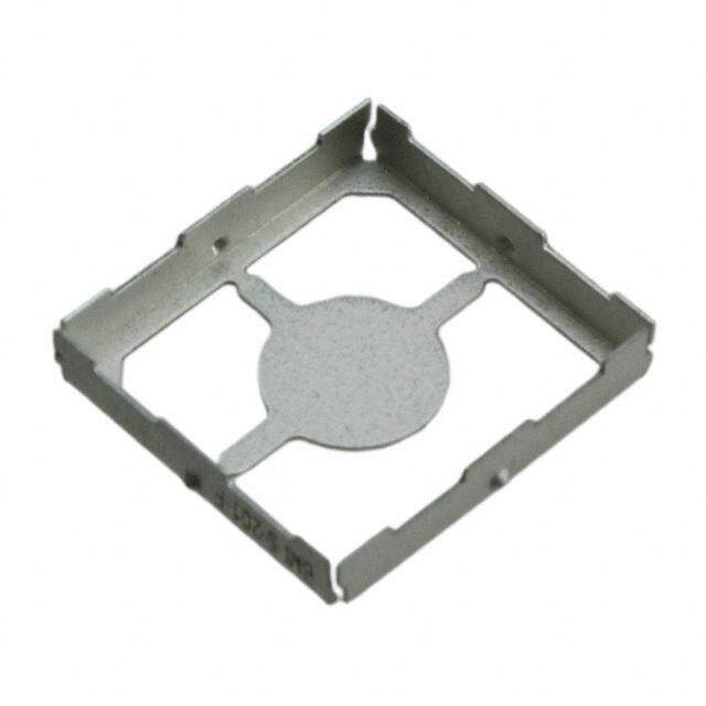
ICGOO电子元器件商城为您提供BMI-S-205-C由Laird Technologies设计生产,在icgoo商城现货销售,并且可以通过原厂、代理商等渠道进行代购。 BMI-S-205-C价格参考。Laird TechnologiesBMI-S-205-C封装/规格:RF 屏蔽, RF Shield Cover 1.018" (25.86mm) X 1.518" (38.56mm) Vent Holes in Pattern Adhesive。您可以下载BMI-S-205-C参考资料、Datasheet数据手册功能说明书,资料中有BMI-S-205-C 详细功能的应用电路图电压和使用方法及教程。
Laird Technologies EMI 的 BMI-S-205-C 属于 RF(射频)屏蔽产品系列,主要用于电磁干扰 (EMI) 和射频干扰 (RFI) 的防护。以下是该型号的应用场景:

1. 电子设备的射频屏蔽
   BMI-S-205-C 可广泛应用于需要高频率屏蔽效能的电子设备中,例如通信设备、医疗仪器、工业自动化设备等。它能够有效减少外部射频信号对敏感电子元件的干扰,同时防止内部射频信号泄漏。

2. 移动通信设备
   在手机、平板电脑和其他无线通信设备中,BMI-S-205-C 能够提供可靠的射频屏蔽,确保设备在高频环境下的稳定运行,避免信号串扰和数据传输错误。

3. 汽车电子系统
   随着汽车智能化的发展,车载信息娱乐系统、导航模块和自动驾驶传感器等都需要高水平的射频屏蔽。BMI-S-205-C 可以保护这些系统免受外界射频干扰,同时确保其正常工作。

4. 医疗设备
   在医疗领域,如 MRI 机器、超声波设备和心电图仪等,射频干扰可能导致测量不准确或设备故障。BMI-S-205-C 提供的屏蔽解决方案可以保障设备的精确性和可靠性。

5. 物联网 (IoT) 设备
   IoT 设备通常包含多个无线模块,容易受到射频干扰的影响。BMI-S-205-C 可以为这些设备提供有效的屏蔽,确保无线通信的稳定性和安全性。

6. 航空航天与国防
   在航空航天和国防领域,射频屏蔽对于保护关键通信和导航系统至关重要。BMI-S-205-C 的高性能屏蔽能力适用于卫星通信、雷达系统和军用通信设备。

7. 消费类电子产品
   包括智能手表、蓝牙耳机和智能家居设备在内的消费类产品,也需要射频屏蔽来保证性能。BMI-S-205-C 的小型化设计和高效屏蔽特性非常适合这些应用。

总之,BMI-S-205-C 是一种适用于多种行业的高性能射频屏蔽解决方案,能够满足现代电子设备对电磁兼容性 (EMC) 的严格要求。
| 参数 | 数值 |
| 产品目录 | |
| 描述 | BOARD SHIELD 1.0X1.5" COVER |
| 产品分类 | |
| 品牌 | Laird Technologies EMI |
| 数据手册 | http://www.lairdtech.com/WorkArea/linkit.aspx?LinkIdentifier=id&ItemID=2924http://www.lairdtech.com/WorkArea/linkit.aspx?LinkIdentifier=id&ItemID=5765 |
| 产品图片 |
|
| 产品型号 | BMI-S-205-C |
| rohs | 无铅 / 符合限制有害物质指令(RoHS)规范要求 |
| 产品系列 | - |
| 产品培训模块 | http://www.digikey.cn/PTM/IndividualPTM.page?site=cn&lang=zhs&ptm=25191 |
| 产品目录绘图 |
|
| 产品目录页面 | |
| 其它名称 | 903-1017 |
| 包装 | 散装 |
| 安装类型 | 卡入式 |
| 宽度-总 | 1.000" (25.40mm) |
| 标准包装 | 250 |
| 特色产品 | http://www.digikey.cn/product-highlights/cn/zh/laird-emi-two-piece-board-level-shields/3367 |
| 类型 | 盖 |
| 通风 | 通风孔,按样式排列 |
| 长度-总 | 1.500"(38.10mm) |
| 高度-总 | 0.236" (6.00 mm) |


PDF Datasheet 数据手册内容提取
global solutions : local support ª | Board Level Shields and Contacts www.lairdtech.com
Laird Technologies is the world-leader in the design and supply of customized performance-critical products for wireless and other advanced electronic applications. Laird Technologies partners with its customers to help find solutions for applications in various industries such as: Network Equipment Telecommunications Data Communications Automotive Electronics Computers Aerospace Military Medical Equipment Consumer Electronics Laird Technologies offers its customers unique product solutions, dedication to research and development and a seamless network of manufacturing and customer support facilities located all across the globe. global solutions : local support ™ www.lairdtech.com www.lairdtech.com
TABLE OF CONTENTS INTRODUCTION TO BOARD LEVEL SHIELDS AND CONTACTS Board Level Shields and Contacts . . . . . . . . . . . . . . . . . . . . . . 2 Design Engineering . . . . . . . . . . . . . . . . . . . . . . . . . . . . . . . . 2 Prototyped Parts . . . . . . . . . . . . . . . . . . . . . . . . . . . . . . . . . . 2 Packaging Automation . . . . . . . . . . . . . . . . . . . . . . . . . . . . . . 2 Quality ISO 9001:2000 Certified . . . . . . . . . . . . . . . . . . . . . . 2 RoHS Statement . . . . . . . . . . . . . . . . . . . . . . . . . . . . . . . . . . . 2 STANDARD DESIGN SHIELDS AND CONTACTS 97-2000 Shields (Series 97-2000) . . . . . . . . . . . . . . . . . . . . . 3 Printed Circuit Board Shields (Series 97-860, 866, 870) . . . . . 5 Standard Surface Mount Shields One-Piece and Two-Piece . . . . . 6 Part No . BMIS-101 and 201 . . . . . . . . . . . . . . . . . 7 Part No . BMIS-102 and 202 . . . . . . . . . . . . . . . . . 8 Part No . BMIS-103 and 203 . . . . . . . . . . . . . . . . . 9 Part No . BMIS-104 and 204 . . . . . . . . . . . . . . . . 10 Part No . BMIS-105 and 205 . . . . . . . . . . . . . . . . 11 Part No . BMIS-106 and 206 . . . . . . . . . . . . . . . . 12 Part No . BMIS-107 and 207 . . . . . . . . . . . . . . . . 13 Part No . BMIS-208 . . . . . . . . . . . . . . . . . . . . . . . 14 Part No . BMIS-209 . . . . . . . . . . . . . . . . . . . . . . . 14 Part No . BMIS-210 . . . . . . . . . . . . . . . . . . . . . . . 15 EZ PeelTM Standard Shields . . . . . . . . . . . . . . . . . . . . . . . . . . 16 Part No . 97-2002 . . . . . . . . . . . . . . . . . . . . . . . . 17 Part No . 97-2003 . . . . . . . . . . . . . . . . . . . . . . . . 17 Part No . 97-2004 . . . . . . . . . . . . . . . . . . . . . . . . 17 Part No . 97-2005 . . . . . . . . . . . . . . . . . . . . . . . . 17 Standard Precision Electronic Contacts . . . . . . . . . . . . . . . . 18 Part No . BMIC-001 . . . . . . . . . . . . . . . . . . . . . . . 18 Part No . BMIC-002 . . . . . . . . . . . . . . . . . . . . . . . 18 Part No . BMIC-004 . . . . . . . . . . . . . . . . . . . . . . . 18 Part No . BMIC-006 . . . . . . . . . . . . . . . . . . . . . . . 19 Part No . BMIC-007-01 . . . . . . . . . . . . . . . . . . . . . 19 Part No . BMI-C-010-* . . . . . . . . . . . . . . . . . . . . . 19 CUSTOM DESIGN SHIELDS AND CONTACTS Introduction . . . . . . . . . . . . . . . . . . . . . . . . . . . . . . . . . . . . . 20 One-Piece Shield Design . . . . . . . . . . . . . . . . . . . . . . . . . . . 20 Two-Piece Shield Design . . . . . . . . . . . . . . . . . . . . . . . . . . . 20 EZ PeelTM Shield Design . . . . . . . . . . . . . . . . . . . . . . . . . . . . . 21 Multi-Compartmental Shield Design . . . . . . . . . . . . . . . . . . 21 Drawn Board Level Shields (Series 97-2100) . . . . . . . . . . . . 21 Custom Precision Electronic Contacts . . . . . . . . . . . . . . . . . 22 Products/specifications are subject to change. Please contact Laird Technologies for potential changes in product specifications. www.lairdtech.com 1
INTRODUCTION TO BOARD LEVEL SHIELDS AND CONTACTS BOARD LEVEL SHIELDS AND CONTACTS PACKAGING AUTOMATION For innovations in packaging and in shield assemblies, a dedicated in-house Laird Technologies one-piece shields, multi-compartmental shields and automation engineering department routinely develops new automation precision contacts are designed to maximize performance in a minimum technologies . An array of packaging options is available for shields and timeframe . Metal electronic components are packaged for surface mount contacts, including tape and reel, tray, tube and bulk . Laird Technologies applications suitable for a variety of industries . Laird Technologies expertise is tape and reel packaging allows for the lowest installed cost and is Electronic in numerous key divisions to ensure each part optimizes individual applications . Industries Association (EIA) 481 compliant . Tape sizes are supplied on Here's how we help you succeed: 13-inch and15-inch diameter reels . A transparent cover tape allows component verification and inspection without having to remove or handle DESIGN ENGINEERING components . Before contacting a Laird Technologies engineer, determine the right board level shield or contact design for the application . Based upon specifications, Two-piece shields, including multi-compartmental shields, are packaged as Laird Technologies experts will use the latest Pro-Engineering/AutoCAD either assembled or unassembled parts . systems to develop part designs in hours . Drawing upon extensive experience Laird Technologies innovative automation engineering allows engineers to with application engineering, advanced design and materials engineering, design small and complex contacts requiring pick-up zones of 1 mm and Laird Technologies engineers will solve the most complex board level shield weighing less than 0 .01 grams . Custom automation equipment places the and contact problems . miniature contacts into tape pockets quickly and cost effectively . The tape and reel packaged parts are ready for installation onto printed circuit boards Laird Technologies engineers and technical specialists look beyond the initial using standard pick-and-place equipment . component to the entire application . Each engineer will create the ideal Vision recognition marks, such as holes and tabs, can orient parts . This finished product at the best value . Example considerations include board eliminates an added step and leads to faster production . Laird Technologies layout, EMI shielding requirements and grounding terminations . ensures each design has an adequate pick-up area for pick-and-place FAST TURNAROUND ON PROTOTYPES equipment, without sacrificing performance . Accuracy and speed in the prototyping process are crucial in creating a QUALITY-ISO 9001:2000 CERTIFIED successful product . Laird Technologies staff quickly responds within days with By placing a premium on quality, Laird Technologies has received the highest a prototyped part . By manufacturing with precision, the prototype meets the ratings on major customer qualification audits . Customers continually rank tolerances of a progressive die manufacturing production environment . Laird Technologies among one of the top suppliers for quality and If design modifications are necessary, Laird Technologies prototype performance . The board level shield and contact facilities are ISO 9001:2000 department is flexible and will address changes without affecting the certified by TUV-America Inc . delivery of the prototyped part . To ensure parts are delivered at optimum performance and meet specifications, all prototyped parts are 100% Built-in quality systems, including Laird Technologies proprietary 100% inspected on critical dimensions . automated co-planarity inspection for board level shields, ensures rigid standards are met through all stages of operations (design, production, Laird Technologies also provides pre-production support to help get the shipping, as well as prompt customer concern resolution) . production line up and running quickly . Parts designed in pre-production can be supplied while progressive die tools are being produced . Laird Technologies executes real-time, automated SPC on all critical With manufacturing plants throughout North America, Asia and Europe dimensions throughout production . By taking these measurements, quality Laird Technologies provides worldwide access to parts and offers the capacity assurance technicians can make necessary adjustments on the spot to ensure to handle any size job . quality parts are on schedule . Maintaining traceability with SPC results for all jobs; captured data includes operator, shift, raw material, job number, work center and more . Additionally, non-contact, automated coordinate measuring machines (CMM) are located throughout Laird Technologies factory floors . RoHS Statement All products in this catalog, along with all other Board Level Shield products are compliant to the RoHS standards . 2 www.lairdtech.com
STANDARD DESIGN SHIELDS AND CONTACTS 97-2000 SHIELDS Range of Pin and Pad Mounting Styles Maximizes Flexibility The 97-2000 series allows mounting options including various pin styles for through-hole mounting or pad styles for surface mounting . The frame material forms the walls of the enclosure and the cover is held securely in place by spring force alone . Covers can be easily removed and replaced to provide access to components . Large or small quantities are easily manufactured using automated tooling, short run capabilities or photochemical machining operations . • 97-2000 frame heights from 0 .130" (3,0 mm) to 1" (25,4 mm), with other heights available upon request • Cover design permits retention even when severe shock or vibration are a consideration; cover designed for easy removal and replacement • Design allows for automated pick-and-place operations • Locking feature on frame guarantees corner joint stability • Variety of pin style options available including a surface mountable style • Pin location can be customized to hole location or a defined pitch • Frames can be hand-formed or supplied formed and with cover assembled • A modified pin style is available for extra retention in through hole application • All parts are treated as custom, so standards exist • RoHS compliant ^Test performance in accordance with MIL-STD-285 using an aperture the same size as t he 1-3/4" x 2" (44,5 mm x 5,08 mm) PC shield as reference . Measurement below 400 MHz were not possible because of the aperture attenuation . 97-2000 SHIELDS Frame Height and Pin Option PIN STYLE 1. FIGURE 1. Through Hole with Standoff Hole Pattern Layout .130 to 1.000 (3,3 to 25,4) Under Cover Height Range Pitch 1/2 Pitch + 0.006 1/2 Pitch + 0.006 (Consult engineering for irregular hole patterns .) All dimensions shown are in inches (millimeters) unless otherwise specified . www.lairdtech.com 3
STANDARD DESIGN SHIELDS AND CONTACTS PIN STYLE 2. FIGURE 2. Surface Mount Tab Pitch Selection Placement and Corner Locking Feature .130 to 1.000 .130 to 1.000 (3,3 to 25,4) (3,3 to 25,4) Under Cover Under Cover Height Range Height Range Any pitch (P) with minimum of .200 (5,08) PIN STYLE 3. FIGURE 3. Through Hole Cover Detail Standard cover material thickness 0.010" (0,25 mm) tin plated phosphor bronze, in coated steel or stainless steel .130 to 1.000 (3,3 to 25,4) Under Cover Height Range Phantom lines indicate optional L-shaped Type on configuration random locations PIN STYLE 4. Flush Surface Mount .130 to 1.000 (3,3 to 25,4) Under Cover Height Range All dimensions shown are in inches (millimeters) unless otherwise specified . 4 www.lairdtech.com
STANDARD DESIGN SHIELDS AND CONTACTS High-Performance, Readily Available PRINTED CIRCUIT BOARD SHIELDS Laird Technologies standard board level shields and contacts offer readily available, low-cost EMI shield and contact alternatives to custom designed solutions . A variety of sizes and designs are available to choose from, so finding a product that delivers the desired results for a project is easy . 97-860 Modifications are an option if the standard product does not fully fit space requirement constraints . Laird Technologies standard shields and contacts are available in a range of 97-866 material choices, and all allow for full solderability . Standard shield offerings incorporate proprietary design criteria for maximum performance and are available in one-piece and two-piece designs . Laird Technologies standard contacts base materials include beryllium copper, phosphor bronze, nickel and stainless steel . Many plating options are offered for maximum electrical current carrying performance . Patent No. 4,754,101 97-870 PC SHIELD DIMENSIONS APPROX . SERIES A B C D E LENGTH FT (M) Front View 97-860 ( .1532,20) .(10,415) .(31,220) .(00,380) ( .1400,20) (72,56 ) 97-860 and 97-866 97-866 ( .2802,80) .(10,415) .(31,220) .(00,380) ( .1770,80) (72,56 ) 25 ft. (7,6 m) 97-870 1(2 .81,240) .(10,415) .(31,220) .(00,380) (125 .0,40) (72,56 ) Other heights and custom-designed cover configurations available . Consult sales department . Typical Mounting Configuration .200 (5,08) .115 Dia. (2,92) Typ. Clearance Flat Cover Front View 97-870 Side View Nominal Cover Thickness-Any Conductive Material 25 ft. (7,6 m) D .020 (0,51) .300 (7,62) B Spring Finger Standard Strip A E Solder Tab Mounting Pin C Mount .300 (7,62) Hole Centerline All dimensions shown are in inches (millimeters) unless otherwise specified . www.lairdtech.com 5
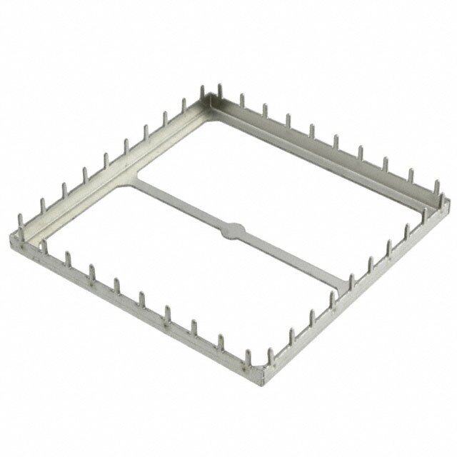
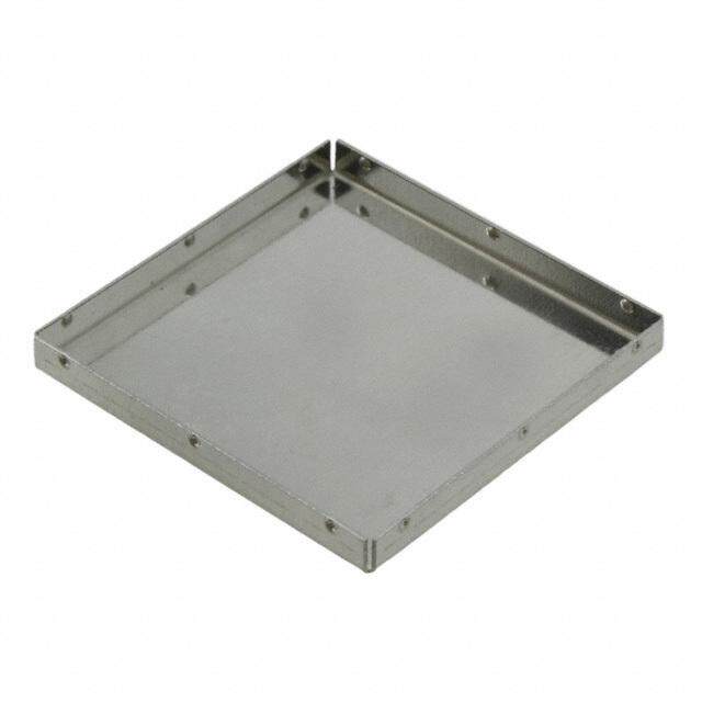
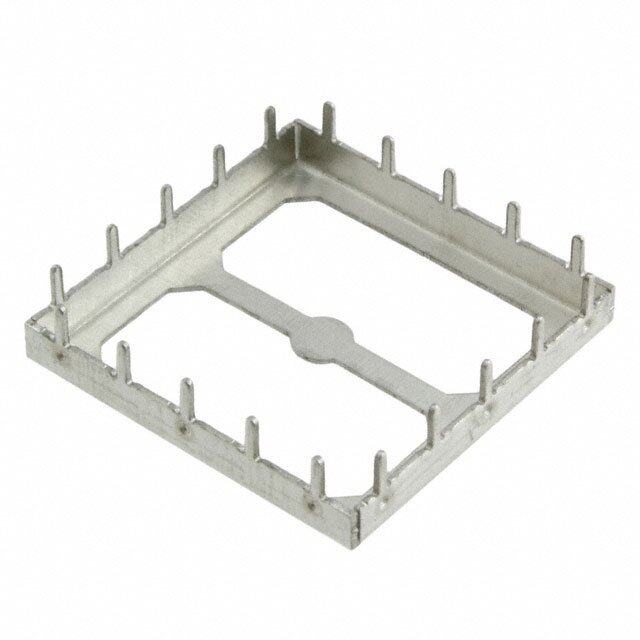
STANDARD DESIGN SHIELDS AND CONTACTS STANDARD SURFACE MOUNT SHIELDS ONE-PIECE Off the Shelf, On Spec and On Budget One-piece standard surface mount shields offer six sides of protection, with the sixth side being the board itself . One-piece designs offer economical shielding protection where access to covered components is not necessary . There are no tooling costs associated with either the one and/or two-piece design . STANDARD SURFACE MOUNT SHIELDS TWO-PIECE Reduce Board Damage From Inspection and Repairs Two-piece standard surface mount shields offer users the flexibility to inspect or repair shielded components without risking board damage by removing the entire shield or incurring tooling costs . Covers snap on and off with ease, which makes repair of the component under the shield quicker and easier and reduces board re-work . Two-piece shields are available unassembled* and are designed to survive drop, shock and no-rattle tests . *Pre-assembly is an option . Consult sales . STANDARD ONE-PIECE BOARD LEVEL SHIELDS TYPICAL PROPERTIES & PERFORMANCE - ALL PART NUMBERS NUPAMRBTE R MOLAEVXNEIRGMATULHLM MOAWVXIEDIMRTAHULM MOHAVEXEIIGRMAHULTLM C WATARIDRPTIEEH R C APTARITRPCIEHE R PEPRA RRTESE L WEIGHT CPoR-OplPaEnRaTriYty TELSTTW MI-1ET1H19OD <0R,E1S0U mLTm BMI-S-101 (1 .533,686 ) (1 .427,160 ) ( .21,0504 ) 24 mm 20 mm 1000 0 .4 g Solderability ANSI/JSTD-002 >99% Solderability MIL-STD-202 Method 208 >99% BMI-S-102 (1 .665,500) (1 .665,500 ) ( .31,4620) 32 mm 24 mm 700 0 .7 g Adhesion ASTM B-571 Passes BMI-S-103 (12 .60,3221) (12 .60,3221 ) ( .52,0008) 44 mm 32 mm 300 1 .6 g 3 Axis Mechanical Shock LTES-461 Passes BMI-S-104 (13 .22,6000) (13 .22,6000 ) ( .62,3060) 44 mm 36 mm 225 2 .4 g DESIGN PARAMETERS - ALL PART NUMBERS BMI-S-106 (13 .64,5803) (13 .33,2668 ) ( .52,0008) 56 mm 40 mm 300 2 .4 g PIDCIKA-MUPE TSEPROT MATERIAL MATERIAL THICKNESS CAMRARTIEERR ITAALPE BMI-S-105 (13 .85,0100 ) (12 .50,0400 ) ( .62,3060) 56 mm 32 mm 250 2 .5 g 6 mm or greater 0,20 mm CRS Tin 0,20 mm LTIMS-LCB BMI-S-107 (14 .47,4377 ) (14 .47,4377 ) ( .93,8745) 56 mm 56 mm 120 6 .5 g Cover tape material REEL DIAMETER REEL MATERIAL PACKAGING 330 mm (101, 102, 103, STANDARD TWO-PIECE BOARD LEVEL SHIELD FRAMES 104, 201 202 203 204) LTIMS-PSA 381 mm (105, 106, 107, Plastic EIA-481 PART OVERALL OVERALL OVERALL TAPE TAPE PARTS PER 205, 206, 207, 208, NUMBER LEGNTH WIDTH HEIGHT WIDTH PITCH REEL 209, 210) BMI-S-201-F (1 .533,686 ) (1 .427,160 ) ( .21,0504) 24 mm 20 mm 1000 BMI-S-202-F (1 .665,500) (1 .665,500 ) ( .31,4620) 32 mm 24 mm 700 BMI-S-203-F (12 .60,3221) (12 .60,3212 ) ( .52,0008) 44 mm 32 mm 300 BMI-S-209-F (12 .91,5366 ) (3 .722,080 ) ( .72,7050 ) 56 mm 28 mm 400 BMI-S-204-F (13 .22,6000) (13 .22,6000 ) ( .62,3060) 44 mm 36 mm 225 BMI-S-206-F (13 .64,5803 ) (13 .33,2668 ) ( .52,0008) 56 mm 40 mm 300 BMI-S-205-F (13 .85,0100) (12 .50,0400 ) ( .62,3060) 56 mm 44 mm 250 BMI-S-210-F (14 .47,3022) (13 .02,0510 ) ( .31,1080) 56 mm 40 mm 450 BMI-S-207-F (14 .47,4377) (14 .47,4377 ) ( .93,8745) 56 mm 56 mm 120 BMI-S-208-F (13 .95,5690 ) (13 .95,5690 ) ( .72,7060 ) 56 mm 48 mm 200 All dimensions shown are in inches (millimeters) unless otherwise specified . 6 www.lairdtech.com
STANDARD DESIGN SHIELDS AND CONTACTS STANDARD SURFACE MOUNT SHIELD ONE-PIECE DESIGN SPECIFICATIONS NUPAMRBTE R DMOIMAVXEENIRMASUILOLMN MOHAVEXEIIGRMAHULTLM CARWRIIEDRT HTAPE CARPRIITECRH TAPE PARRTESE LPER A• PWPoLrIkCsA eTxIcOeNptSio:nally well BMI-S-101 (1 .35,3686 xx .1427,67 0) ( .21,0504 ) 24 mm 20 mm 1000 in small component areas • 48 VQFP Dimensions (mm) Footprint Carrier Tape APPLICATIONS: STANDARD SURFACE MOUNT SHIELD • Works exceptionally well TWO-PIECE in small component areas • 48 VQFP DESIGN SPECIFICATIONS NUPAMRBTE R DMOIMAVXEENIRMASUILOLMN MOHAVEXEIIGRMAHULTLM CARWRIIEDRT HTAPE CARPRIITECRH TAPE PARRTESE LPER BMI-S-201-F (1 .35,3686 xx .1427,670) ( .21,0504 ) 24 mm 20 mm 1000 The cover is ordered as a separate part . The part number is BMI-S-201-C and is packaged in the same quantity as the frame . Dimensions (mm) Footprint Carrier Tape www.lairdtech.com 7
STANDARD DESIGN SHIELDS AND CONTACTS STANDARD SURFACE MOUNT SHIELD ONE-PIECE PART NO. BMI-S-102 DESIGN SPECIFICATIONS APPLICATIONS: NUPAMRBTE R DMOIMAVXEENIRMASUILOLMN MOHAVEXEIIGRMAHULTLM CARWRIIEDRT HTA PE CARPRIITECRH TAPE PARTS PER REEL •• 4484 , V4Q8F QPFP BMI-S-102 (1 .66,5500 xx .1665,05 0) ( .31,4620 ) 32 mm 24 mm 700 Dimensions (mm) Footprint Carrier Tape STANDARD SURFACE MOUNT SHIELD TWO-PIECE PART NO. BMI-S-202 DESIGN SPECIFICATIONS NUPAMRBTE R DMOIMAVXEENIRMASUILOLMN MOHAVEXEIIGRMAHULTLM CARWRIIEDRT HTAPE CARPRIITECRH TAPE PARRTESE LPER APPLICATIONS: • 48 VQFP BMI-S-202-F (1 .66,5500 xx .1665,05 0) ( .31,4620 ) 32 mm 24 mm 700 • 44, 48 QFP The cover is ordered as a separate part . The part number is BMI-S-202-C and is packaged in the same quantity as the frame . Dimensions (mm) Footprint Carrier Tape 8 www.lairdtech.com
STANDARD DESIGN SHIELDS AND CONTACTS STANDARD SURFACE MOUNT SHIELD ONE-PIECE DESIGN SPECIFICATIONS NUPAMRBTE R DMOIMAVXEENIRMASUILOLMN MOHAVEXEIIGRMAHULTLM TACPAER WRIIEDRT H TACPAER PRIITECRH PARRTESE LPER A• P3P2L, I4C4A, T5I2O pNinS :PLCC BMI-S-103 (12 .60,3221 xx 12 .60,3221 ) ( .52,0008 ) 44 mm 32 mm 300 • 121, 169 BGA • 48, 100 VQFP • 44, 48, 64, 80 QFP Dimensions (mm) Footprint Carrier Tape STANDARD SURFACE MOUNT SHIELD TWO-PIECE DESIGN SPECIFICATIONS APPLICATIONS: NUPAMRBTE R DMOIMAVXEENIRMASUILOLMN MOHAVEXEIIGRMAHULTLM TACPAER WRIIEDRT H TACPAER PRIITECRH PARRTESE LPER • 32, 44, 52 pin PLCC • 121, 169 BGA BMI-S-203-F (12 .60,3221 xx 12 .60,3221 ) ( .52,0008 ) 44 mm 32 mm 300 • 48, 100 VQFP The cover is ordered as a separate part . The part number is BMI-S-203-C and is packaged in the same • 44, 48, 64, 80 QFP quantity as the frame . Dimensions (mm) Footprint Carrier Tape www.lairdtech.com 9
STANDARD DESIGN SHIELDS AND CONTACTS STANDARD SURFACE MOUNT SHIELD ONE-PIECE DESIGN SPECIFICATIONS NUPAMRBTE R DMOIMAVXEENIRMASUILOLMN MOHAVEXEIIGRMAHULTLM TACPAER WRIIEDRT H TACPAER PRIITECRH PARRTESE LPER A• P1P2L1I,C 1A6T9I,O 2N25S :BGA BMI-S-104 (13 .22,6000 xx 13 .22,6000 ) ( .62,3060) 44 mm 36 mm 225 • 32, 44, 52, 68 PLCC • 48, 100 VQFP • 44, 48, 64, 80, 100 QFP Dimensions (mm) Footprint Carrier Tape STANDARD SURFACE MOUNT SHIELD APPLICATIONS: TWO-PIECE • 121, 169, 225 BGA • 32, 44, 52, 68 PLCC DESIGN SPECIFICATIONS • 48, 100 VQFP NUPAMRBTE R DMOIMAVXEENIRMASUILOLMN MOHAVEXEIIGRMAHULTLM TACPAER WRIIEDRT H TACPAER PRIITECRH PARRTESE LPER • 44, 48, 64, 80, 100 QFP BMI-S-204-F (13 .22,6000 xx 13 .22,6000 ) ( .62,3060 ) 44 mm 36 mm 225 The cover is ordered as a separate part . The part number is BMI-S-204-C and is packaged in the same quantity as the frame . Dimensions (mm) Footprint Carrier Tape 10 www.lairdtech.com
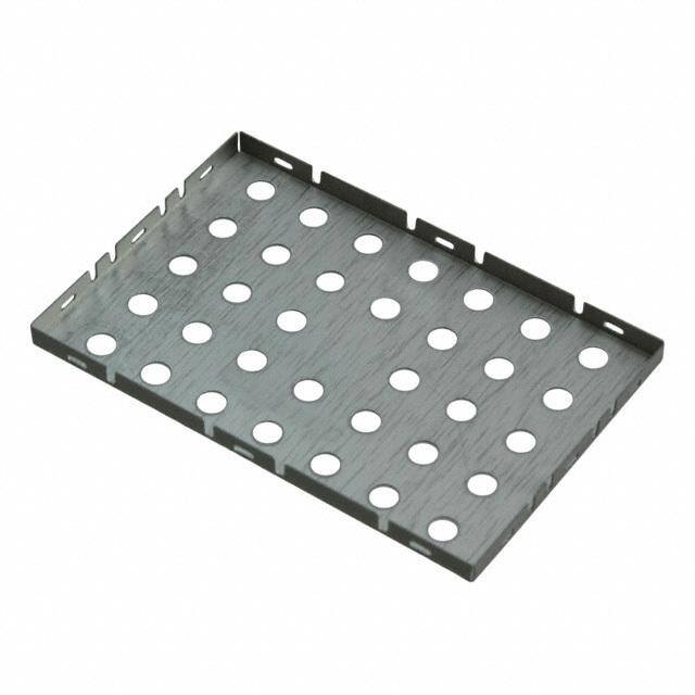
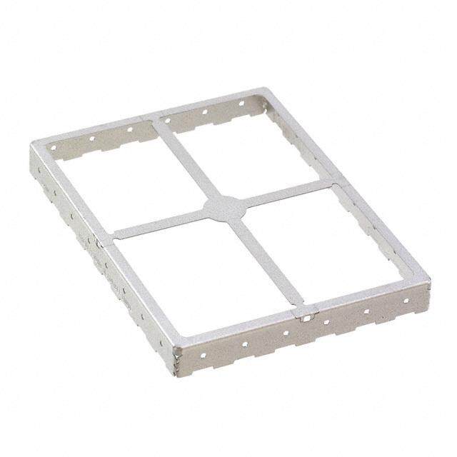
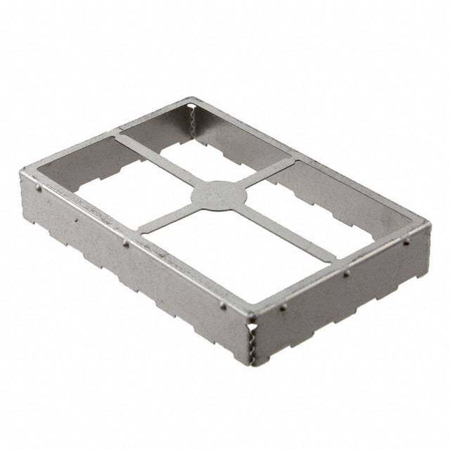
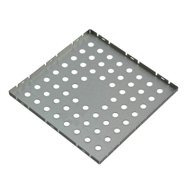
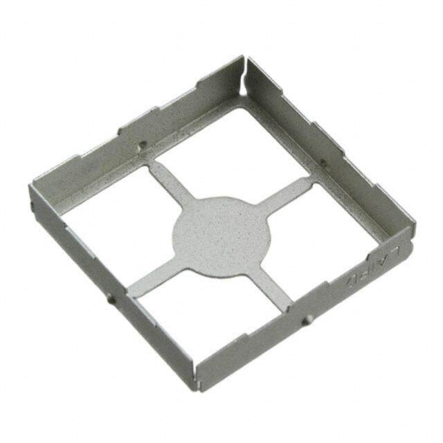
STANDARD DESIGN SHIELDS AND CONTACTS STANDARD SURFACE MOUNT SHIELD ONE-PIECE DESIGN SPECIFICATIONS APPLICATIONS: NUPAMRBTE R DMOIMAVXEENIRMASUILOLMN MOHAVEXEIIGRMAHULTLM TACPAER WRIIEDRT H TACPAER PRIITECRH PARRTESE LPER • 121 BGA • 32, 44, 52 PLCC BMI-S-105 (13 .85,0100 xx 12 .50,0400 ) ( .62,3060 ) 56 mm 32 mm 250 • 48, 100 VQFP • 44, 48, 64, 80, 100 QFP Dimensions (mm) Footprint Carrier Tape STANDARD SURFACE MOUNT SHIELD TWO-PIECE PART NO. BMI-S-205 DESIGN SPECIFICATIONS NUPAMRBTE R DMOIMAVXEENIRMASUILOLMN MOHAVEXEIIGRMAHULTLM TACPAER WRIIEDRT H TACPAER PRIITECRH PARRTESE LPER A• P1P2L1I CBAGTAIONS: BMI-S-205-F (13 .85,0100 xx 12 .50,0400 ) ( .62,3060 ) 56 mm 44 mm 250 •• 3428,, 4140,0 5 V2Q PFLPCC The cover is ordered as a separate part . The part number is BMI-S-205-C and is packaged in the same • 44, 48, 64, 80, 100 QFP quantity as the frame . Dimensions (mm) Footprint Carrier Tape www.lairdtech.com 11
STANDARD DESIGN SHIELDS AND CONTACTS STANDARD SURFACE MOUNT SHIELD ONE-PIECE PART NO. BMI-S-106 DESIGN SPECIFICATIONS NUPAMRBTE R DMOIMAVXEENIRMASUILOLMN MOHAVEXEIIGRMAHULTLM TACPAER WRIIEDRT H TACPAER PRIITECRH PARRTESE LPER A• P1P2L1I,C 1A6T9I,O 2N25S :BGA BMI-S-106 (13 .64,5803 xx 13 .33,2668 ) ( .52,0008 ) 56 mm 40 mm 300 •• 3428,, 4140,0 5 V2Q, F6P8 PLCC • 44, 48, 64, 80, 100 QFP Dimensions (mm) Footprint Carrier Tape STANDARD SURFACE MOUNT SHIELD TWO-PIECE PART NO. BMI-S-206 DESIGN SPECIFICATIONS NUPAMRBTE R DMOIMAVXEENIRMASUILOLMN MOHAVEXEIIGRMAHULTLM TACPAER WRIIEDRT H TACPAER PRIITECRH PARRTESE LPER APPLICATIONS: BMI-S-206-F (13 .64,5803 xx 13 .33,2668 ) ( .52,0008 ) 56 mm 40 mm 300 •• 13221, 4, 146, 592, 2, 6285 PBLGCAC Tqhuea nctoitvye ra sis t ohred ferraemd ea .s a separate part . The part number is BMI-S-206-C and is packaged in the same • 48, 100 VQFP • 44, 48, 64, 80, 100 QFP Dimensions (mm) Footprint Carrier Tape 12 www.lairdtech.com
STANDARD DESIGN SHIELDS AND CONTACTS STANDARD SURFACE MOUNT SHIELD ONE-PIECE BMI-S-107 DESIGN SPECIFICATIONS APPLICATIONS: NUPAMRBTE R DMOIMAVXEENIRMASUILOLMN MOHAVEXEIIGRMAHULTLM TACPAER WRIIEDRT H TACPAER PRIITECRH PARRTESE LPER • Supplied in 56 mm EIA standard carrier tape • 121, 169, 225, 313 BGA BMI-S-107 (14 .47,4377 xx 14 .47,4377 ) ( .93,8745 ) 56 mm 56 mm 120 • 32, 44, 52, 68, 84 PLCC • 48, 100, 208 VQFP • 44, 48, 64, 80, 100, 120, 160 QFP Dimensions (mm) Footprint Carrier Tape STANDARD SURFACE MOUNT SHIELD APPLICATIONS: TWO-PIECE BMI-S-207 • 121, 169, 225, 313 BGA DESIGN SPECIFICATIONS • 32, 44, 52, 68, 84 PLCC • 48, 100, 208 VQFP NUPAMRBTE R DMOIMAVXEENIRMASUILOLMN MOHAVEXEIIGRMAHULTLM TACPAER WRIIEDRT H TACPAER PRIITECRH PARRTESE LPER • 44, 48, 64, 80, 100, 120, 160 QFP BMI-S-207-F (14 .47,4377 xx 14 .47,4377 ) ( .93,8745 ) 56 mm 56 mm 120 The cover is ordered as a separate part . The part number is BMI-S-207-C and is packaged in the same quantity as the frame . Dimensions (mm) Footprint Carrier Tape www.lairdtech.com 13
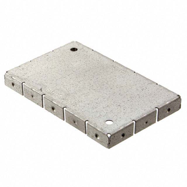
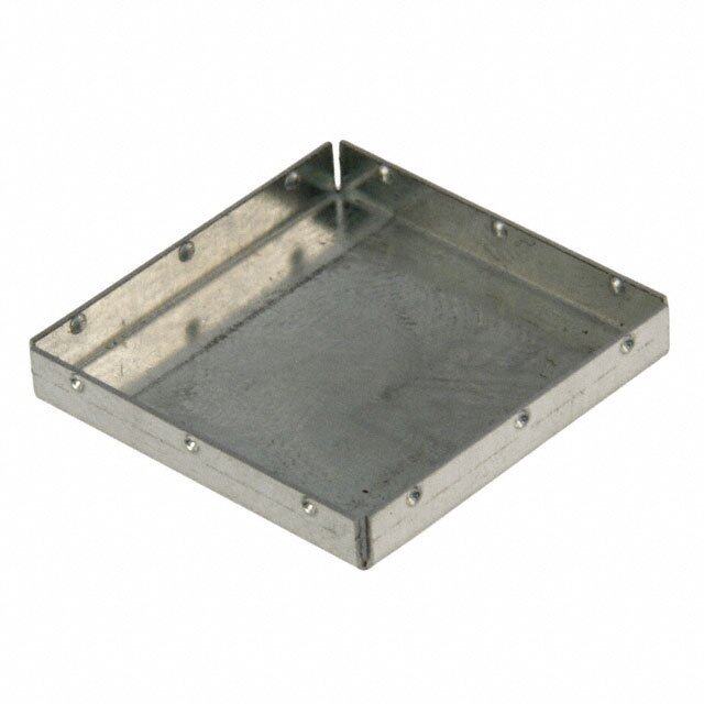
STANDARD DESIGN SHIELDS AND CONTACTS STANDARD SURFACE MOUNT SHIELD TWO-PIECE BMI-S-208 DESIGN SPECIFICATIONS NUPAMRBTE R DMOIMAVXEENIRMASUILOLMN MOHAVEXEIIGRMAHULTLM TACPAER WRIIEDRT H TACPAER PRIITECRH PARRTESE LPER BMI-S-208-F (13 .95,5690 xx 13 .95,5690 ) ( .72,7060 ) 56 mm 48 mm 200 The cover is ordered as a separate part . The part number is BMI-S-208-C and is packaged in the same quantity as the frame . Dimensions (mm) Footprint 39,60 6,00 40,20 1TY,0P0 38,10 40,40 36,30 34,10 30,30 19,80 28,10 24,30 1,50 x 2 22,10 18,30 1,50 0,00 0,00 16,10 00,005,1 19,80 38,10 39,60 0,00 40,20 1120,,3100 6,30 4,10 0,00 0,50 7,00 3 .00 0,00 4,106,30 10,10 12,30 16,1018,30 22,1024,30 28,1030,30 34,1036,30 40,40 TYP 0,10 0,003,306,309,3012,3015,3018,3021,3024,3027,3030,3033,3036,30 STANDARD SURFACE MOUNT SHIELD TWO-PIECE BMI-S-209 DESIGN SPECIFICATIONS NUPAMRBTE R DMOIMAVXEENIRMASUILOLMN MOHAVEXEIIGRMAHULTLM TACPAER WRIIEDRT H TACPAER PRIITECRH PARRTESE LPER BMI-S-209-F (12 .91,5366 xx 01 .87,2580 ) ( .72,7050 ) 44 mm 28 mm 400 The cover is ordered as a separate part . The part number is BMI-S-209-C and is packaged in the same quantity as the frame . Dimensions (mm) Footprint R0,25 x 4 3,00X Z 1TY,0P0 6,00 19,10 18,50 16,10 19,30 17,00 X 16,00 x 2 Z 1,50 x 2 13,75 11,55 9,25 3,00 0,00 7,75 2,5001 ,,x05 200 0,00 26,9626,96 5,55 0,00 00,01,502,50 x 2 13,9314,6815,43 6,86 x 227,8629,36 0TY,5P0 0,00 4,98 7,18 10,9813,18 16,9819,18 22,9825,18 30,16 2 3,00 0,002,98 x 25,73 8,98 x 211,7314,98 x 217,7320,98 x 223,73 26,98 x 2 14 www.lairdtech.com
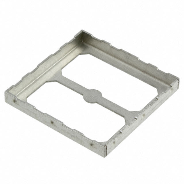
STANDARD DESIGN SHIELDS AND CONTACTS STANDARD SURFACE MOUNT SHIELD TWO-PIECE BMI-S-210 DESIGN SPECIFICATIONS NUPAMRBTE R DMOIMAVXEENIRMASUILOLMN MOHAVEXEIIGRMAHULTLM TACPAER WRIIEDRT H TACPAER PRIITECRH PARRTESE LPER BMI-S-210-F (14 .47,3020 xx 13 .02,0510 ) ( .31,1080 ) 56 mm 40 mm 120 The cover is ordered as a separate part . The part number is BMI-S-210-C and is packaged in the same quantity as the frame . Dimensions (mm) Footprint 1,00 TYP 31,30 2x 28,75 2X 26,55 2X 22,75 2X 20,55 2X 16,75 2X 14,55 2X 10,75 2X 8,55 3,00 A B 2X 4,75 31,10 2X 2,55 28,10 A B 27,55 x2 0,00 24,30 21,55 x2 18,30 1,50 x2 16915,,235,,50535 0 x 2x2 0,00 2X 3,30 2X 5,50 2X 9,302X 11,50 2X 15,302X 17,50 2X 21,302X 23,50 2X 27,30 2X 29,50 2X 33,302X 35,50 2X 39,302X 41,50 44,80 3,00 3,55 x2 0,00 0,00 0,00 41,6044,60 0TY,5P0 2,40 0,00 4,30 x27,0510,30 x213,0516,30 x219,0522,30 x225,0528,30 x231,0534,30 x237,0540,30 x2 www.lairdtech.com 15
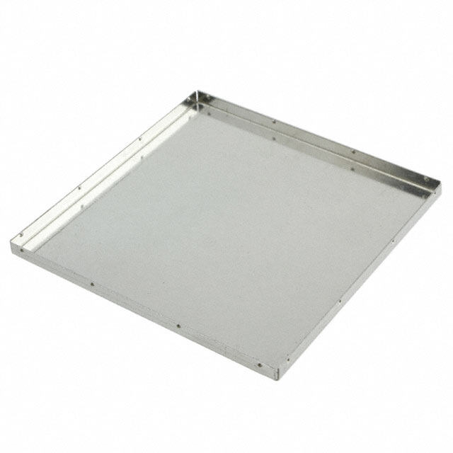
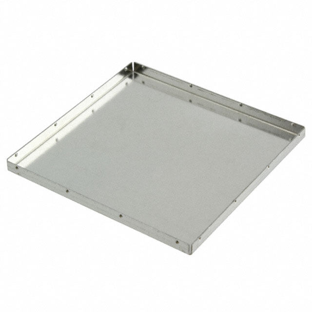
STANDARD DESIGN SHIELDS AND CONTACTS EZ PEELTM STANDARD SHIELDS For Quick and Easy Access to Board Level Components Laird Technologies offers four standard sizes of EZ Peel removable cover board level shields . These patented shields have a solid top, scored to allow peel-off when access to board level components within the shield is required . The peel-off feature prevents damage to the board and components by eliminating the need for labor intensive de-soldering, which often results in increased scrap . Peeling off the cover is accomplished by using a small starter hole for simple removal . This hand operation requires minimal force using a hook scriber or tweezers . After repair, replacement or adjustment of internal components, the shield can be resealed using a replacement cover . Laird Technologies offers two replacement cover options: a snap-in cover and a dish cover . The snap-in cover utilizes a lance and hole design . The replacement cover TABLE 1 snaps into place and locks into a lance feature on the frame of the original shield . REPLACEMENT LID OPTIONS EZ PEEL SHIELD PART NUMBER SNAP-IN LID NUMBER DISH LID NUMBER The other option is a dish cover that gets soldered into place on the board . 97-2002 97-2007 97-2014 The dish shape allows for self-location of the cover for soldering . 97-2003 97-2006 97-2013 Standard EZ Peel board level shields can be packaged in tape and reel 97-2004 Not Available 97-2016 formats for easy SMT installation using conventional pick-and-place 97-2005 97-2008 97-2015 equipment . The four standard sizes are also available without the EZ Peel (scored) feature . • Easy removal of scored cover area • Only 1 .5 lbs . force required for cover removal Original EZ Peel Board Level Shield • Simple replacement technique for cover • Used on surface mount or through-hole applications • Shield retains all physical properties after PCMCIA/ JEIDA testing for shock, bending, torque, drop and vibration • CRS 1008/1010 (tin plated) for solderability • RoHS compliant Snap-in Cover Application Dish Cover Application ^After removal of scored section and ^After removal of scored section and application of snap-in cover application of dish cover All dimensions shown are in (inches) millimeters unless otherwise specified . 16 www.lairdtech.com
STANDARD DESIGN SHIELDS AND CONTACTS EZ PEELTM STANDARD SHIELDS PROFILES/DIMENSIONS EZ Peel Board Level Shields Solder Pad Footprint Carrier Tape 97-2002 97-2003 97-2004 97-2005 All dimensions shown are in (inches) millimeters unless otherwise specified . www.lairdtech.com 17
STANDARD DESIGN SHIELDS AND CONTACTS STANDARD PRECISION ELECTRONIC CONTACTS Laird Technologies standard precision electronic contacts ground, carry current and signals and interconnect boards and devices . A wide variety of plating options allow for the maximum electrical current carrying performance . An array of designs in a standard format are ready for production . Installed costs are lower with our tape and reel . Typical Deflection Behavior of BMIC-001, BMIC-004, BMIC-006, and BMIC-007-01 STANDARD PRECISION ELECTRONIC CONTACTS MATERIAL VARIATIONS NUPAMRBTE R MATERIAL APVLAAITLIANBGLSE APPTLYICPIACTAIOL NS PEPRA RRTESE L STANDARD PRECISION ELECTRONIC CONTACTS BMI-C-001 0,10 mm BeCu Gold enGerrgoyu ncdairnrygin, g 3000 NUPAMRBTE R MATERIAL APVLAAITLIANBGLSE APPTLYIPCIACTAIOL N S PARTS PER REEL BMI-C-001-SN 0,10 mm BeCu Tin enGerroguyn cdairnrgyi,ng 3000 BMI-C-001 0,10 mm BeCu Gold enGerrgoyu ncdairnrygi,ng 3000 BMI-C-002 0,10 mm BeCu Gold enGerrgoyu ncdairnrygin, g 3500 BMI-C-001-SN 0,10 mm BeCu Tin enGerrgoyu ncdairnrygi,n g 3000 BMI-C-004 0,10 mm BeCu Gold enGerrgoyu ncdairnrygin, g 1400 BMI-C-004-SN 0,10 mm BeCu Tin enGerrgoyu ncdairnrygin, g 1400 BMI-C-006 0,10 mm BeCu Tin enGerrgoyu ncdairnrygin, g 3500 BMI-C-007-01 0,13 mm BeCu Tin enGerrgoyu ncdairnrygin, g 2300 BMI-C-010-* 0,20 mStmee Slpring Tin Standoff, support 3500 (Var) Material properties are for reference only . Product testing by purchaser is recommended to confirm . Laird Technologies assumes no liability for product failure unless specifically stated in writing . STANDARD PRECISION ELECTRONIC CONTACTS NUPAMRBTE R MATERIAL APVLAAITLIANBGLSE APPTLYIPCIACTAIOL N S PEPRA RRTESE L BMI-C-004 0,10 mm BeCu Gold enGerrgoyu ncdairnrygi,n g 1400 Footprint BMI-C-004-SN 0,10 mm BeCu Tin enGerrgoyu ncdairnrygi,n g 1400 STANDARD PRECISION ELECTRONIC CONTACTS Side View Front View CONTACTS MATERIAL APVLAAITLIANBGLSE APPTLYIPCIACTAIOL N S PEPRA RRTESE L 5,97 4,31 5,18 BMI-C-002 0,10 mm BeCu Gold enGerrgoyu ncdairnrygi,n g 3500 2,08 1,52 Top View 5,18 30.000o 3,81 Right Side 4,313,66 Front View Footprint 0,65 5,73 All dimensions shown are in (inches) millimeters unless otherwise specified . 18 www.lairdtech.com
STANDARD DESIGN SHIELDS AND CONTACTS PART NO. BMI-C-006 PART NO. BMIC-007-01 NUPAMRBTE R MATERIAL APVLAAITLIANBGLSE APPTLYIPCIACTAIOL N S PEPRA RRTESE L NUPAMRBTE R MATERIAL APVLAAITLIANBGLSE TYPICAL APPLICATIONS PARTS PER REEL BMI-C-006 0,10mm BeCu Tin Grounding, energy carrying 3500 BMI-C-007-01 0,13 mm Tin Grounding, energy carrying 2300 Front View Side View Front View Side View 2,30 1.50 1,50 RO.10 TYP 2,00 INSIDER0,10 TYP 2,86 INSIDE 1,40 2,00 3,20 2,48 1,50 RO,55X2 INSIDE 2,30 1.00 1,00 Footprint 3,30 2,00 1,50 Footprint 2,00 2,12 STANDARD SIZED PROTOTYPE PARTS PART NO. BMI-C-010-* Standard prototype parts are available in select one-piece and two-piece sizes . Pricing based on volume and required prototype methods cost . Parts are manu- CONTACTS MATERIAL APVLAAITLIANBGLSE APPTLYICPIACTAIOL NS PEPRA RRTESE L factured in the prototype department to production tolerances with lead times typically less than two weeks . BMI-C-010-* 0,20 mm Spring Steel Tin Standoff, support 3500 (Var) Front View Side View Shields are made from high quality steel for excellent shielding performance across a wide frequency range . The tin plated surface provides excellent solderability and A compatibility with lead-free processes . Upon request, part drawings and solder pad B layouts are available . ONE PIECE PART NUMBER BLS TYPE DIMENSIONS in (mm) R0,30 C LENGTH WIDTH HEIGHT LT-BLS-139 one piece BLS 0 .736 (18,70) 0 .575 (14,60) 0 .236 (6,00) LT-BLS-137 one piece BLS 1 .193 (30,30) 0 .583 (14,80) 0 .236 (6,00) Footprint LT-BLS-138 one piece BLS 1 .193 (30,30) 0 .961 (24,40) 0 .236 (6,00) -0 -1 -2 -3 LT-BLS-141 one piece BLS 1 .346 (34,20) 0 .575 (14,60) 0 .236 (6,00) 1,77 LT-BLS-136 one piece BLS 1 .433 (36,40) 0 .685 (17,40) 0 .236 (6,00) 3,00 LT-BLS-143 one piece BLS 1 .551 (39,40) 1 .390 (35,30) 0 .236 (6,00) 1,50 1,80 8,50 TWO PIECE PART NUMBER BLS TYPE DIMENSIONS in (mm) 15,50 LENGTH WIDTH HEIGHT 4,00 LT-BLS-215 two piece 1 .300 (33,02) 1 .065 (27,05) 0 .400 (10,16) LT-BLS-224 two piece 1 .650 (41,91) 1 .375 (34,93) 0 .400 (10,16) LT-BLS-216 two piece 1 .770 (44,96) 1 .065 (27,05) 0 .400 (10,16) A B C LT-BLS-213 two piece 2 .130 (54,10) 1 .065 (27,05) 0 .400 (10,16) * LT-BLS-225 two piece 2 .250 (57,15) 1 .375 (34,93) 0 .400 (10,16) -0 1 .5 1 .27 1 .80 5,00 LT-BLS-219 two piece 2 .756 (70,00) 2 .240 (56,90) 0 .400 (10,16) -1 5 .0 2 .50 1 .27 LT-BLS-229 two piece 2 .775 (70,49) 1 .685 (42,80) 0 .400 (10,16) LT-BLS-226 two piece 2 .800 (71,12) 1 .375 (34,93) 0 .400 (10,16) -2 5 .00 15 .00 1 .27 LT-BLS-227 two piece 3 .375 (85,73) 1 .375 (34,93) 0 .400 (10,16) -3 4 .00 8 .00 1 .27 On two piece BLS, dimensions shown are the exterior frame dimensions . www.lairdtech.com 19
CUSTOM DESIGN SHIELDS AND CONTACTS INTRODUCTION The complexities of today's electronics pose several design challenges . Resolving EMI needs to be balanced with space, weight and production restraints . When designing a custom shielding solution, beginning in the earliest stages of the application design allows effective elimination of EMI while meeting all specifications . Laird Technologies board level shielding experts work through all phases of development . From design, rapid prototyping and pre-production through production and automated packaging, Laird Technologies has the experience to help speed a product to market and stay within budget . ONE-PIECE SHIELD DESIGN Low Cost/Excellent Effectiveness To increase manufacturing throughout and reduce costs, Laird Technologies Custom surface mount shields are available in both one-piece and two- has developed a proprietary in-line production process that includes part for- piece designs . One-piece shields provide six sides of protection, with the mation, wash, assembly, inspection and automated packaging . sixth side being the board itself . One-piece designs offer economical shielding alternatives where access to covered components for repair is not By integrating quality processes, board level shield quality and performance necessary . is ensured from design stage through final packaging . One process is the automated co-planarity inspection system . Laird Technologies replicates the TWO-PIECE SHIELD DESIGN customer application by measuring shields in the same plane as the printed Quick, Easy Repair and Inspection of Covered Components circuit board . This is accomplished without "securing" or "touching" shields, which could throw off measurement and/or deform parts . Laird Technologies Two-piece board level shields offer users the flexibility to inspect or repair measures shields immediately prior to placement into carrier tape at speeds shielded components without having to risk board damage by removing that match automation packing . the entire shield . Covers snap on and off with ease, making repairs quicker and easier, and reducing board re-work . Two-piece shields are available Shield base materials include our exclusive Shield-LiteTM, CRS 1008/1010, pre-assembled or unassembled . Large locking dimples snap into slots on beryllium copper alloys, nickel-silver alloys, copper-based alloys and spring covers to provide mechanical retention force . Smaller grounding dimples steels . All shields are fully solderable . provide electrical grounding for proper shielding and to prevent rattle . Two-piece shields survive drop, shock and no-rattle tests . Here are critical test results: SURFACE MOUNT SHIELDS MATERIAL VARIATIONS • Able to withstand acceleration of 4g from 10 Hz to 2000 Hz for three RAW MATERIAL* THinIC (KmNmE)SS HEAT TREATMENT PLATING COMMENTS hours in each of three planes as per SAE J1455 • Pass EN 50 155 for railway electrical equipment including vibration test CRS1 b0a0s8e/ 1b0o1x 0steel (00 .,010257 ttoo 02 .,029806 ) No heat treatment Tin Pre-plated of 30g from 5 Hz to 200 Hz in 3 directions and a shock test with 500 m/s Beryllium-copper 0 .004 to 0 .008 Heat treatable in Tin, palladium, Pre-tempered & for 11/ms alloys (0,102 to 0,203) all temperatures nickel, gold pre-plated • Pass standard telecommunications drop tests [6 faces, dropped 1 meter Nickel-silver alloys (00 .,010042 ttoo 00 .,041066 ) Stress annealed proF(iupf lruliyes tesaodrl ydw epirtrahob cLleTes s ) No psolaflodtiren rgSaM breiTlqi t uyired onto concrete floor] Coppaellor-ybsased (00 .,010042 ttoo 00 .,031025 ) No heat treatment Tinni, cpkaelll,a gdoiuldm, Prep-rtee-mpplaetreedd & Spring steel (00 .,010562 ttoo 01 .,056204 ) Austemper Tin, niocxkiedle, black Spdreaintpegpr mlpicrianotepidoe nrbtiye s Phospahlolory Bsronze (00 .,010040 ttoo 00 .,052100 ) N/A Tinni, cpkaelll,a gdoiuldm, PreP-treemplpaeteredd & *Other materials may be available, please consult sales . Material properties are for reference only . Product testing by purchaser is recommended to confirm . Laird Technologies assumes no liability for product failure unless specifically stated in writing . 20 www.lairdtech.com
CUSTOM DESIGN SHIELDS AND CONTACTS • Available in cold rolled steel, brass, stainless steel and nickel silver • Molded Compartment Shields and Form-In-Place elastomers can be combined with drawn board level shields to achieve shielding of multiple components with a single part • Available with an EZ Peel scored cover feature; allows for easy top section removal for component repair and re-sealing EZ PEELTM SHIELD DESIGN • Ventilation holes as needed for solder outgassing . Economical Access for Low Incidences of Repairs In cases where there is a low incidence of repairable circuit defects, access may be needed to shielded components . An economical solution is EZ Peel shields . These one-piece shields feature an easy-to-remove top section that can be peeled back using simple tools for access to components . Built-in flexibility controls the ease of removing the top, and the robust design delivers superior flatness . EZ Peel shields are designed to accept a snap-on cover in the same manner as our two-piece shields, following circuit repair . Series 97-2100 MULTI-COMPARTMENTAL SHIELD DESIGN Shield Multiple Circuit Groups Save PCB Space and Production Time Printed circuit boards with multiple circuit groups pose unique design challenges . Shielding these groups separately adversely affects circuit board real estate and increases part count . Multi-compartmental shields allow replacement of three or more single shields with one shield divided into several walled compartments . Installing a single part reduces part count, along with production time through faster pick-and-place speeds . This allows for a reduction the number of parts in inventory, which lowers overhead costs . Multi-compartmental shields feature internal dividing walls of one material thickness and meet all on-board shield requirements for FCC, VDE, CISPR and CE . These shields are available in two-piece designs, either assembled or unassembled . Our unassembled versions allow for automatic optical inspection prior to cover placement . As in all our shielding offerings, Laird Technologies proprietary process for 100% automatic optical inspection verifies co-planarity including inner walls . DRAWN BOARD LEVEL SHIELDS Seamless Corners Address High-Frequency Leakage As microprocessor speeds continue to increase, so does the potential for EMI leakage through the smallest apertures in board level shields . Laird Technologies drawn board level shields are designed to provide additional near-field and far-field circuit isolation (attenuation) at higher frequencies by eliminating the apertures found in the corners of traditional board level solutions . Drawn board level shields utilize small ground trace sizes, thereby preserving space on the circuit board . ^The receive antenna test region from 1 GHz to 10 GHz that defines the Far-Field and Near-Field is 2 .0" and 0 .190", respectfully, from the transmit antenna . This test is performed • Solid corner designs when additional circuit isolation (attenuation) is for worst case orientation . required at higher frequencies Circuit Isolation is a measurement that defines the resultant attenuation level in dB provided • Available in custom heights up to .250" (6,4 mm) with length and width by a PCB shield from an initial reference level as defined in Laird test procedure PDA-PRO- dimensions from .300" (7,6 mm) to 2 .0" (50,8 mm) 027 . • Tape and reel packaging provides an economical and automated SMT Notice: The data set forth in all text, tables, charts, graphs and figures herein are based on samples tested and are attachment method not guaranteed for all samples or applications . Such data are intended as guides and do not reflect product specification for any specific part . www.lairdtech.com 21
CUSTOM DESIGN SHIELDS AND CONTACTS CUSTOM PRECISION ELECTRONIC CONTACTS Gain Maximum Electrical and Carrying Performance From concept to placement, Laird Technologies has the expertise to deliver custom precision surface mount contacts . Using the latest computer simulation techniques, Laird Technologies provides properly designed contacts that ground, carry current and signals, and interconnect boards and devices . Laird Technologies uses basic geometric parameters (length, width, uncompressed height, compressed height, contact force) to conduct Finite Element Analysis (FEA) on your prospective design . With the FEA results, we can then identify the best design to optimize a product's operational performance . Features are incorporated to provide for placement and soldering of the contact onto the circuit board . Laird Technologies offers a wide range of plating options to allow for ^Automated packaging allows for complex and small designs with lower maximum electrical current carrying performance . installed costs . Contact base materials include beryllium copper, phosphor bronze, nickel and stainless steel . All contacts are fully solderable as required . CUSTOM PRECISION ELECTRONIC CONTACTS MATERIAL VARIATIONS TYPE THinIC (KmNmE)SS HEAT TREATMENT PLATING/COATING COMMENTS B1e7ry2l0liu0m, 1 C9o0p, p2e9r0 A, 1llo7y4s: ( .00,008395 ttoo .20,0830) Heat Treatable Tin, palladium, nickel, gold, silver HPerea-tP Tlraetaetde do ra Pso nset cPelasstaedry 5P1h0o,s 5p0h5or, 5B1ro1n, z5e2 A1l,l o5y4s4: ( .00,1004 ttoo .20,2990) N/A Tin, palladium, nickel, gold, silver Pre-Plated or Post Plated 110C, o1p0p2e, r1 A2l2lo, y1s0: 93 ( .00,1056 ttoo .31,1285) N/A Tin, palladium, nickel, gold, silver Pre-Plated or Post Plated 2602,4 201B, 0r2a,6 s28s2 ,A 03l,l5 o20y2s, :63 ,5 2330, ( .00,1004 ttoo .20,2990) N/A Tin, palladium, nickel, gold, silver Pre-Plated or Post Plated Ni7ck7e0l , S7il5ve2r, A76llo2ys: ( .00,1004 ttoo .10,5620) N/A Tin, palladium, nickel, gold, silver (ifS uosldeedr awbilteh inLT u pnrpolpartieedta cryo npdroitcioenss ) 105S0p,r i1n0g6 S5t,e 1e0l A7l4lo, y1s0: 95 ( .00,2008 ttoo .20,0830) Austemper Tin, nickel, black oxide Plated after heat treatment 301, S3ta0i2n,l e3s0s5 S, t3ee1l6 A, l2lo0y1s,: 202 ( .00,1004 ttoo .20,2990) N/A Tin, gold Pre-Plated or Post Plated Stainle4s1s0 S, t4ee2l0 Alloys: ( .00,1004 ttoo .20,2990) Heat Treatable Tin, gold HPerea-tP Tlraetaetde do ra Pso nset cPelasstaedry Titanium Copper ( .00,1004 ttoo .00,3102) N/A Tin, palladium, nickel, gold, silver HPerea-tP Tlraetaetde do ra Pso nset cPelasstaedry Special Alloys: Clad metals ( .00,008395 ttoo .20,0830) N/A Tin, palladium, nickel, gold, silver, palladium-silver Pre-Plated or Post Plated Post Plating Thickness as required N/A Tin, nickel, goldz,i nsiclv, eprh, ozisnpch, abtleack oxide, black N/A Additional material choices are available upon request . Material properties are for reference only . Product testing by purchaser is recommended to confirm . Laird Technologies assumes no liability for product failure unless specifically stated in writing . 22 www.lairdtech.com
NOTES www.lairdtech.com 23
NOTES 24 www.lairdtech.com