ICGOO在线商城 > 射频/IF 和 RFID > 平衡-不平衡变压器 > BD2425N50ATI
 Datasheet下载
- 型号: BD2425N50ATI
- 制造商: Anaren Microwave
- 库位|库存: xxxx|xxxx
- 要求:
| 数量阶梯 | 香港交货 | 国内含税 |
| +xxxx | $xxxx | ¥xxxx |
查看当月历史价格
查看今年历史价格
BD2425N50ATI产品简介:
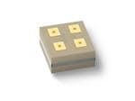
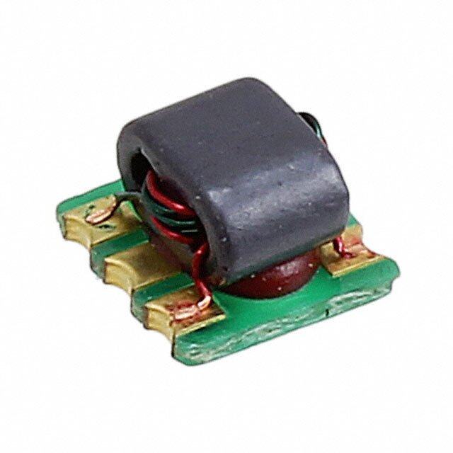
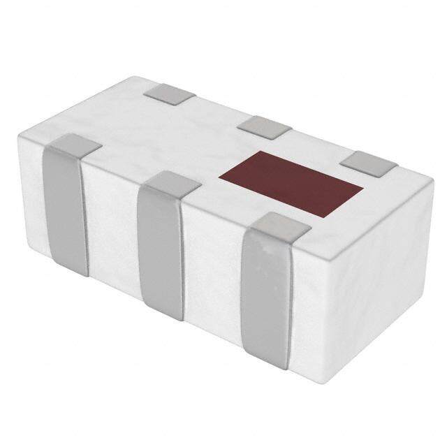
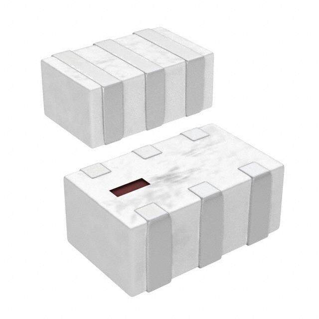
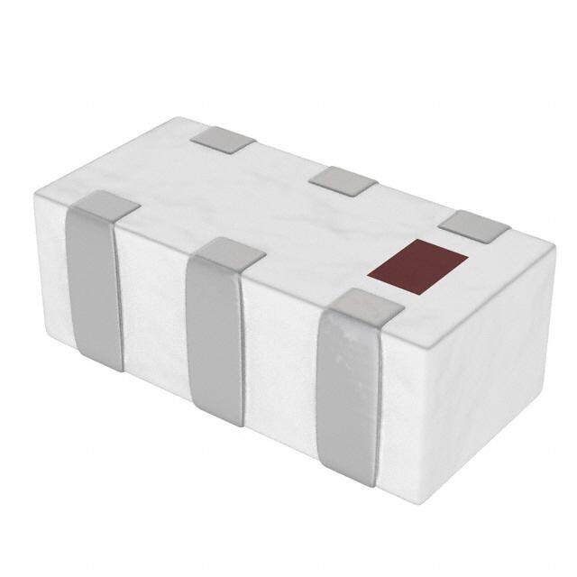
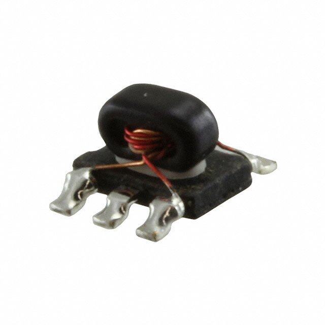
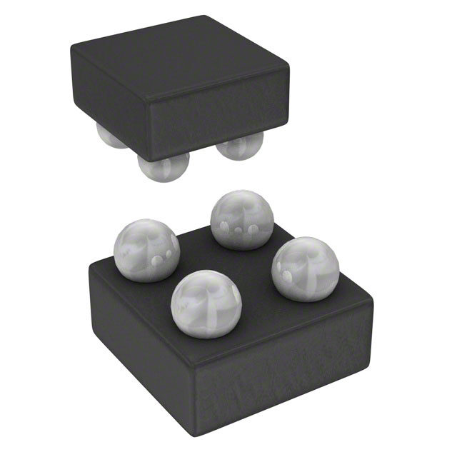
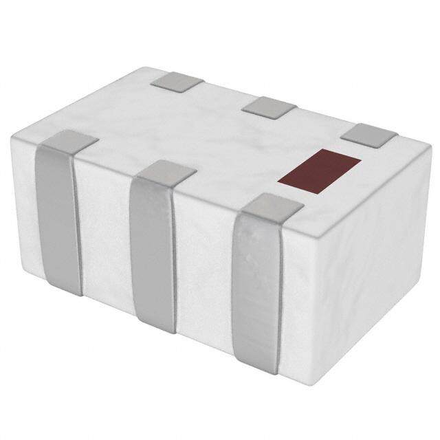
ICGOO电子元器件商城为您提供BD2425N50ATI由Anaren Microwave设计生产,在icgoo商城现货销售,并且可以通过原厂、代理商等渠道进行代购。 BD2425N50ATI价格参考¥1.50-¥4.49。Anaren MicrowaveBD2425N50ATI封装/规格:平衡-不平衡变压器, RF Balun 2.3GHz ~ 2.6GHz 0404 (1010 Metric)。您可以下载BD2425N50ATI参考资料、Datasheet数据手册功能说明书,资料中有BD2425N50ATI 详细功能的应用电路图电压和使用方法及教程。
Anaren品牌的BD2425N50ATI是一款平衡-不平衡变压器(巴伦),主要应用于无线通信系统中。该器件工作频率范围为2.4GHz至2.5GHz,特别适用于ISM(工业、科学和医疗)频段的射频应用。典型应用场景包括Wi-Fi无线局域网(WLAN)、蓝牙通信、ZigBee网络以及物联网(IoT)设备等短距离无线传输系统。

BD2425N50ATI采用表面贴装封装,具有小型化、高集成度的特点,适合空间受限的便携式电子设备。其主要功能是实现差分信号与单端信号之间的转换,常用于射频前端电路中连接功率放大器、射频收发芯片与天线之间,提升信号传输效率并减少电磁干扰。

此外,该巴伦具备良好的阻抗匹配性能(通常为50欧姆系统),有助于降低信号反射、提高系统整体射频性能。由于其高可靠性和稳定性,BD2425N50ATI广泛应用于智能家居设备、无线传感器、无线音频设备及嵌入式无线模块中,是现代高频无线通信设计中的关键无源元件之一。
| 参数 | 数值 |
| 产品目录 | |
| 描述 | XFRMR BALUN RF 2400-2500MHZ 0404信号调节 2.3-2.6GHz 50 Ohm IL=.6dB |
| 产品分类 | |
| 品牌 | Anaren |
| 产品手册 | |
| 产品图片 |
|
| rohs | 符合RoHS无铅 / 符合限制有害物质指令(RoHS)规范要求 |
| 产品系列 | Anaren BD2425N50ATIXinger® |
| mouser_ship_limit | 该产品可能需要其他文件才能进口到中国。 |
| 数据手册 | |
| 产品型号 | BD2425N50ATI |
| RoHS指令信息 | |
| 产品 | Baluns |
| 产品种类 | 信号调节 |
| 介入损耗 | 0.4 dB |
| 其它名称 | 1173-1065-2 |
| 包装 | 带卷 (TR) |
| 商标 | Anaren |
| 商标名 | Xinger |
| 回波损耗(最小值) | 13dB |
| 安装类型 | 表面贴装 |
| 封装 | Reel |
| 封装/外壳 | 4-SMD,无引线 |
| 封装/箱体 | 0404 (1010 metric) |
| 工作温度范围 | - 55 C to + 85 C |
| 工厂包装数量 | 4000 |
| 插入损耗(最大值) | 0.6dB |
| 标准包装 | 4,000 |
| 相位差 | - |
| 端接类型 | SMD/SMT |
| 类型 | Ultral Low Profile Balun |
| 阻抗 | 50 Ohms |
| 阻抗-非平衡/平衡 | - |
| 频率范围 | 2.3GHz ~ 2.6GHz |


- 商务部:美国ITC正式对集成电路等产品启动337调查
- 曝三星4nm工艺存在良率问题 高通将骁龙8 Gen1或转产台积电
- 太阳诱电将投资9.5亿元在常州建新厂生产MLCC 预计2023年完工
- 英特尔发布欧洲新工厂建设计划 深化IDM 2.0 战略
- 台积电先进制程称霸业界 有大客户加持明年业绩稳了
- 达到5530亿美元!SIA预计今年全球半导体销售额将创下新高
- 英特尔拟将自动驾驶子公司Mobileye上市 估值或超500亿美元
- 三星加码芯片和SET,合并消费电子和移动部门,撤换高东真等 CEO
- 三星电子宣布重大人事变动 还合并消费电子和移动部门
- 海关总署:前11个月进口集成电路产品价值2.52万亿元 增长14.8%
PDF Datasheet 数据手册内容提取
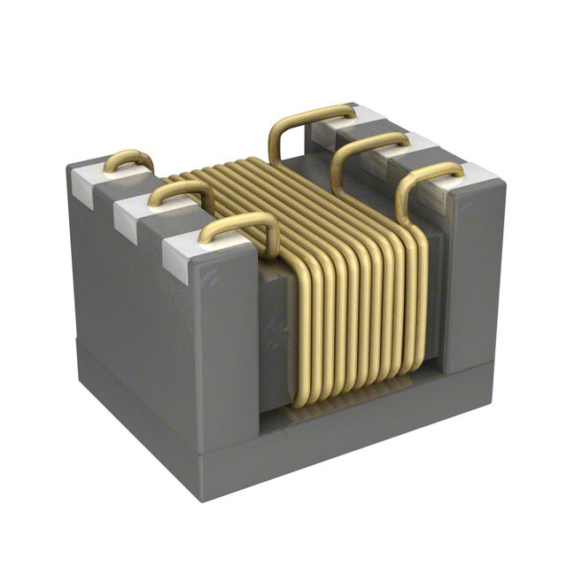
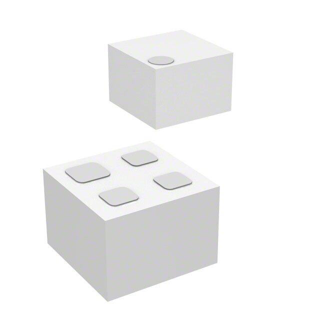
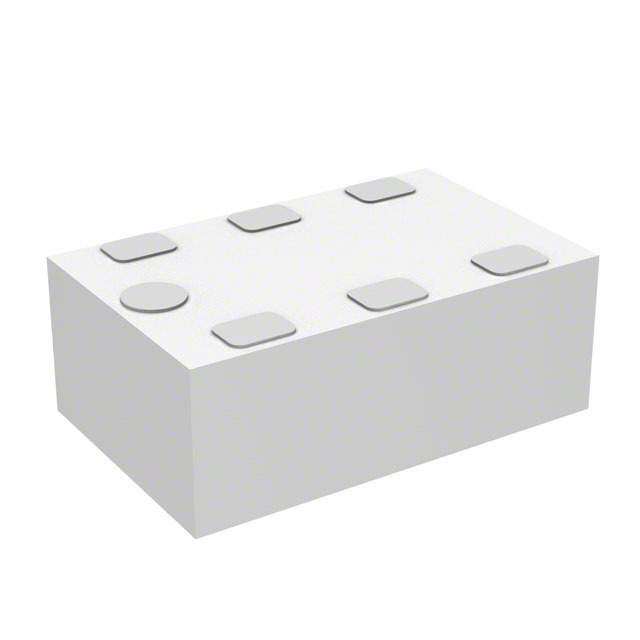
Model BD2425N50ATI Rev A Ultra Low Profile 0404 Balun for TI transceiver CC2500 50Ω to 127+j34Ω Balanced (Anaren Application Note Ann-2003) Description The BD2425N50ATI is a low cost, low profile sub-miniature unbalanced to balanced transformer designed for differential inputs and output locations on modern chipsets in an easy to use surface mount package. The BD2425N50ATI is ideal for high volume manufacturing and delivers higher performance than traditional ceramic baluns. The BD2425N50ATI has an unbalanced port impedance of 50Ω and 127+ j34Ω balanced port impedance. This transformation enables single ended signals to be applied to differential ports on modern integrated chipsets. The output ports have equal amplitude (-3dB) with 180 degree phase differential. The BD2425N50ATI is available on tape and reel for pick and place high volume manufacturing. Detailed Electrical Specifications: Specifications subject to change without notice. Features: ROOM (25°°°°C) 2400 – 2500 MHz Parameter Min. Typ. Max Unit 0.65mm Height Profile 50 Ohm to 2 x 63.5+j17 Ohm Frequency 2300 2600 MHz Low Insertion Loss Unbalanced Port Impedance** 50 Ω Surface Mountable Balanced Port Impedance** 127+j34 Ω Tape & Reel Return Loss** 13 17 dB Non-conductive Surface RoHS Compliant Insertion Loss* ** 0.4 0.6 dB Zigbee Power Handling 1 TBD Watts Operating Temperature -55 +85 ºC * Insertion Loss stated at room temperature (Insertion Loss is approximately 0.1 dB higher at +85 ºC) * Stated performance assumes proper matching network found in application note: ANN-2003 Outline Drawing Top View (Near-side) Side View Bottom View (Far-side) .041+.003 .012 [0.30] [.10.4015+-+..00000.0238] [1.05-+.-0000..00268] [.00.2642±±.000.02654] 0.12 [0.30] 1 2 -0.06 3x.010 [0.25] 4 3 3x.010 [0.25] 4X .020 [0.50] Pin Designation 1 GND / DC Feed + RF GND 2 Unbalanced Port Dimensions are in Inches [Millimeters] 3 Balanced Port Mechanical Outline 4 Balanced Port Tolerances are Non-Cumulative Sales Desk USA: Voice: (800) 544-2414 Fax: (315) 432-9121 Sales Desk Europe: Voice: (+44) 2392 232392 Fax: (+44) 2392 251369
Model BD2425N50ATI Rev A Mounting Configuration: In order for Xinger surface mount components to work optimally, the proper impedance transmission lines must be used to connect to the RF ports. If this condition is not satisfied, insertion loss, Isolation and VSWR may not meet published specifications. All of the Xinger components are constructed from ceramic filled PTFE composites which possess excellent electrical and mechanical stability having X and Y thermal coefficient of expansion (CTE) of 17 ppm/oC. An example of the PCB footprint used in the testing of these parts is shown below. An example of a DC-biased footprint is also shown below. In specific designs, the transmission line widths need to be adjusted to the unique dielectric coefficients and thicknesses as well as varying pick and place equipment tolerances With DC Bias 3X .011 Plated thru [0.29] hole to .008 [0.21] ground 3X .011 [0.29] .014 [0.36] .020 .008 [0.21] [0.50] 3X Transmission Line .020 [0.50] Circuit Pattern Footprint Pad (s) Dimensions are in Inches [Millimeters] Solder Resist Mounting Footprint Sales Desk USA: Voice: (800) 544-2414 Fax: (315) 432-9121 Sales Desk Europe: Voice: (+44) 2392 232392 Fax: (+44) 2392 251369
Model BD2425N50ATI Rev A Packaging and Ordering Information Parts are available in reel and are packaged per EIA 481-2. Parts are oriented in tape and reel as shown below. Minimum order quantities are 4000 per reel. See Model Numbers below for further ordering information. ØA ØC ØD TABLE 1 QUANTITY/REEL REEL DIMENSIONS (inches [mm]) B ØA 7.00 [177.8] B 0.32 [8.0] 4000 ØC 2.0 [50.8] ØD 0.512 [13.0] Sales Desk USA: Voice: (800) 544-2414 Fax: (315) 432-9121 Sales Desk Europe: Voice: (+44) 2392 232392 Fax: (+44) 2392 251369
Mouser Electronics Authorized Distributor Click to View Pricing, Inventory, Delivery & Lifecycle Information: A naren: BD2425N50ATI