ICGOO在线商城 > 连接器,互连器件 > 矩形连接器 - 针座,公插针 > B7PS-VH(LF)(SN)
(SN).jpg)
 Datasheet下载
- 型号: B7PS-VH(LF)(SN)
- 制造商: JST
- 库位|库存: xxxx|xxxx
- 要求:
| 数量阶梯 | 香港交货 | 国内含税 |
| +xxxx | $xxxx | ¥xxxx |
查看当月历史价格
查看今年历史价格
B7PS-VH(LF)(SN)产品简介:
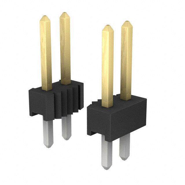
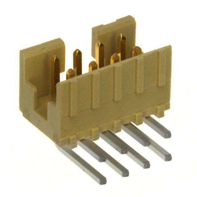
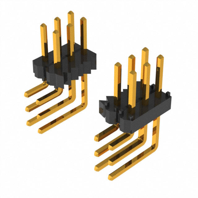
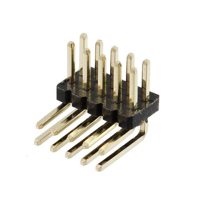
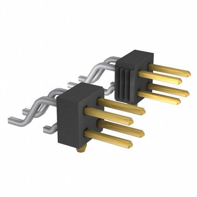
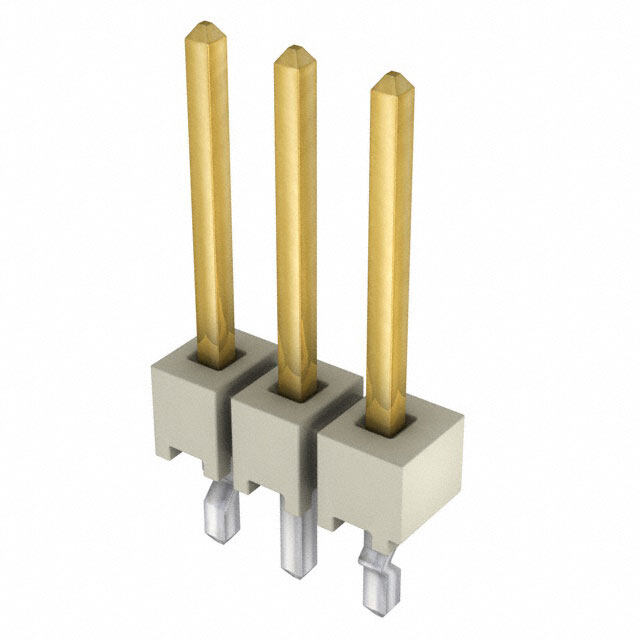
ICGOO电子元器件商城为您提供B7PS-VH(LF)(SN)由JST设计生产,在icgoo商城现货销售,并且可以通过原厂、代理商等渠道进行代购。 B7PS-VH(LF)(SN)价格参考。JSTB7PS-VH(LF)(SN)封装/规格:矩形连接器 - 针座,公插针, 7 位 接头 连接器 0.156"(3.96mm) 通孔,直角 锡。您可以下载B7PS-VH(LF)(SN)参考资料、Datasheet数据手册功能说明书,资料中有B7PS-VH(LF)(SN) 详细功能的应用电路图电压和使用方法及教程。
JST Sales America Inc. 生产的型号为 B7PS-VH(LF)(SN) 的矩形连接器(针座,公插针)是一种广泛应用于电子设备和系统的连接器。以下是该型号的一些典型应用场景:

 1. 汽车电子
   - 用于车载电子系统中的信号传输,例如传感器、控制单元(ECU)、仪表盘、照明系统等。
   - 在电动车和混合动力车中,可作为电池管理系统(BMS)或其他电力电子模块的连接组件。

 2. 工业自动化
   - 应用于工业机器人、PLC控制器、伺服驱动器和其他自动化设备中的信号和电源连接。
   - 提供稳定的电气连接,确保设备在高振动或恶劣环境下的可靠运行。

 3. 消费类电子产品
   - 用于家用电器(如空调、冰箱、洗衣机)的内部电路板连接。
   - 在音频/视频设备中,作为信号传输接口,支持高质量的数据传递。

 4. 医疗设备
   - 用于便携式医疗设备(如血压计、血糖仪)或大型医疗仪器(如超声波设备、监护仪)中的连接。
   - 其紧凑设计和可靠性使其适合对精度要求较高的医疗应用。

 5. 通信与网络设备
   - 在路由器、交换机、基站等通信设备中,用作内部模块之间的连接。
   - 支持高速数据传输,同时具备良好的抗干扰能力。

 6. 航空航天与国防
   - 在需要高可靠性和耐久性的环境中,如无人机、卫星、导航系统等,该连接器可用于关键部件的连接。
   - 其耐用性和稳定性能够应对极端温度和高震动条件。

 7. 照明系统
   - 用于LED灯具、智能照明控制系统中的电源和信号连接。
   - 提供高效的电能传输,同时减少能量损耗。

 8. 物联网(IoT)设备
   - 在智能家居、传感器网络和其他物联网设备中,作为数据采集和传输的关键组件。
   - 其小型化设计便于集成到各种紧凑型设备中。

 特点总结:
- 尺寸紧凑:适合空间受限的设计。
- 高可靠性:适用于多种复杂环境。
- 易于安装:简化生产和维护流程。
- 多样化兼容性:适配多种电路板和设备需求。

总之,B7PS-VH(LF)(SN) 连接器凭借其出色的性能和广泛适用性,成为众多行业和领域的理想选择。
| 参数 | 数值 |
| 产品目录 | |
| 描述 | CONN HEADER VH SIDE 7POS 3.96MM |
| 产品分类 | |
| 品牌 | JST Sales America Inc |
| 数据手册 | |
| 产品图片 |
|
| 产品型号 | B7PS-VH(LF)(SN) |
| rohs | 无铅 / 符合限制有害物质指令(RoHS)规范要求 |
| 产品系列 | VH |
| 产品目录绘图 |
|
| 产品目录页面 | |
| 其它名称 | (D)B7PS-VH(LF)(SN) |
| 加载的针脚数 | 全部 |
| 包装 | 散装 |
| 安装类型 | 通孔,直角 |
| 排数 | 1 |
| 排距 | - |
| 标准包装 | 250 |
| 特性 | - |
| 端接 | |
| 紧固类型 | 锁销滑道 |
| 触头类型 | 公形引脚 |
| 触头配接长度 | 0.303"(7.70mm) |
| 触头镀层 | 锡 |
| 触头镀层厚度 | - |
| 连接器类型 | 接头,无罩 |
| 配套产品 | /product-detail/zh/VHR-7N/455-1181-ND/608622 |
| 针脚数 | 7 |
| 间距 | 0.156"(3.96mm) |
| 颜色 | 自然色 |


- 商务部:美国ITC正式对集成电路等产品启动337调查
- 曝三星4nm工艺存在良率问题 高通将骁龙8 Gen1或转产台积电
- 太阳诱电将投资9.5亿元在常州建新厂生产MLCC 预计2023年完工
- 英特尔发布欧洲新工厂建设计划 深化IDM 2.0 战略
- 台积电先进制程称霸业界 有大客户加持明年业绩稳了
- 达到5530亿美元!SIA预计今年全球半导体销售额将创下新高
- 英特尔拟将自动驾驶子公司Mobileye上市 估值或超500亿美元
- 三星加码芯片和SET,合并消费电子和移动部门,撤换高东真等 CEO
- 三星电子宣布重大人事变动 还合并消费电子和移动部门
- 海关总署:前11个月进口集成电路产品价值2.52万亿元 增长14.8%
PDF Datasheet 数据手册内容提取
VH CONNECTOR 3.96mm pitch/Disconnectable Crimp style connectors 6 Specifications ––––––––––––––––––– 5 4 3 2 • Current rating: 10 A AC, DC(AWG #16) 6 1 TSJ • Voltage rating: 250 V AC, DC • Temperature range: -25˚C to +85˚C (including temperature rise in applying electrical current) • Contact resistance: Initial value/ 10 mΩmax. After environmental tests/ 20 mΩmax. • Insulation resistance: 1,000 MΩmin. • Withstanding voltage: 1,500 VAC/minute • Applicable wire: AWG #22 to #16 • Applicable PC board thickness: 1.6 mm Note: Do not branch in parallel current which exceeds the rated current. If branched in parallel, current imbalance or other problems may develop. If it is absolutely necessary to branch such a large current in parallel, be sure to use contacts made of phosphor bronze. Design the circuits without causing imbalance and provide an extra margin for each circuit. This small, field-proven connector for *Refer to "General Instruction and Notice when using printed circuit boards is reliable and has a Terminals and Connectors" at the end of this catalog. large current carrying capacity. It can be * Contact JST for details. used with a wide variety of signal, power *Compliant with RoHS. supply, and output circuits that appear in Standards––––––––––––––––––––––– consumer electronic products. 0 Recognized E60389 • Proven box contact 1 Certified LR20812 • Compact connector with a large capacity 2 • Secure contact and mounting R75122 PC board layout and Assembly layout Locking header Locking header Top entry type Side entry type 10.5 3.96±0.05 min (20.5) 3.96±0.05 7.2 * 5 8 10. φ1.65 +00.1 16.5) φ1.65 +00.1 ( * 7.2min *11.0 max. when used with the VR connector receptacle. Locking header Shrouded header 10.5 Side entry type with PCB stabilizer 3.96±0.05 1.5±0.05 3.96±0.05 (21) φ1.4 +00.1 Circuit No.1 10.5 ±0.053.4 (16.5) φ1.65 +00.1 φ1.65 +00.1 19 Note:1. The above figure is the figure viewed from soldering side. 2. Tolerances are non-cumulative: ±0.05 mm for all centers. 3. Please consider the pattern layout design in case of applying the large current. 4. Hole dimensions differ according to the type of PC board and piercing method. The dimensions above should serve as a guideline. Contact JST for details. 1
VH CONNECTOR Contact Applicable wire Insulation O.D. Model No. mm2 AWG# (mm) Q'ty/reel SVH-21T-P1.1 0.33〜0.83 22〜18 1.7〜3.0 4,500 10.6 SVH-41T-P1.1 0.5 〜1.25 20〜16 1.7〜3.0 3,500 3 4 4.2 Material and Finish Phosphor bronze, tin-plated (reflow treatment) 8 3. RoHS compliance Note: When using retainer mountable type housing, applicable wire's insulation O. D. shall be 1.7 to 2.2 mm. Crimping Applicator Crimping Applicator Contact Contact machine Crimp applicator Dies Crimp applicator with dies machine Crimp applicator Dies Crimp applicator with dies MKS-L MK/SVH-21-11 APLMK SVH21-11 MKS-L MK/SVH-41-11 APLMK SVH41-11 SVH-21T-P1.1 AP-K2N SVH-41T-P1.1 AP-K2N *MKS-SC SC/SVH-21-11 APLSC SVH21-11 − − − Note: *Strip-crimp applicator Housing N type M type Retainer mountable type B B B A A A Circuit No.1 5.7 10.5 Circuit No.1 6.2 10.6 Circuit No.1 5.7 10.5 13.3 13.3 15 Model No. Dimensions (mm) Note: 1. Models identified as VHR-( ) M incorporate measures to prevent Circuits Retaine Q'ty/ electric shock and are thus safer in regard to high voltages. N type M type mountable type A B bag 2. The applicable housing for 2 circuits shrouded header is "VHR-2N" 2 VHR-2N VHR-2M VHRR-2N 3.96 7.86 1,000 only. "VHRR-2N" is not applicable. 3 VHR-3N VHR-3M VHRR-3N 7.92 11.82 (*) 3. Contact JST for Glow Wire compliant connectors. 4 VHR-4N VHR-4M ― 11.88 15.78 1,000 (*) N / M type ; 1,000 5 VHR-5N VHR-5M VHRR-5N 15.84 19.74 (*) Retainer mountable type ; 500 6 VHR-6N VHR-6M ― 19.80 23.70 500 7 VHR-7N VHR-7M VHRR-7N 23.76 27.66 500 <For reference> As the color identification, the following alphabet shall be put in the underlined part. 8 VHR-8N ― VHRR-8N 27.72 31.62 500 For availability, delivery and minimum order quantity, contact JST. 9 VHR-9N VHR-9M VHRR-9N 31.68 35.58 500 10 VHR-10N ― ― 35.64 39.54 500 ex. VHR-2N-oo- 11 VHR-11N ― ― 39.60 43.50 500 (blank)…natural (white) BK…black R…red BL…blue M…green D…orange Y…yellow Material PK…pink H…gray PA 6, UL94V-0, natural (white) RoHS compliance Retainer Circuits Model No. A Q'ty/bag 2 VHS-2V 3.70 1,000 circuits2 : 2.6circuits3 to 9 : 4.2 3578 VVVVHHHHSSSS----3578VVVV 122 5377....43354622 1111,,,,000000000000 A 9 VHS-9V 31.28 1,000 Material Glass-filled PA 66, UL94V-0, natural (ivory) RoHS compliance 7.1 2
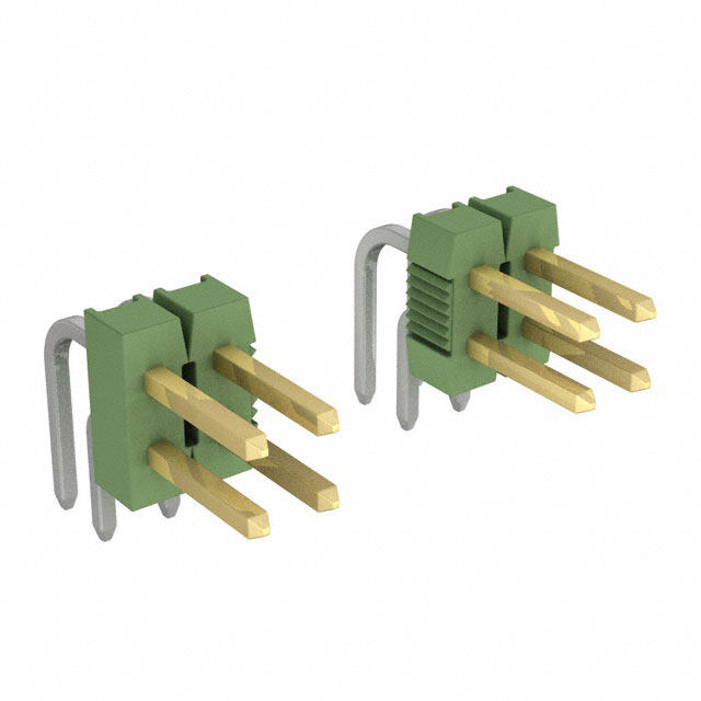
VH CONNECTOR Locking header Model No. Dimensions (mm) Q'ty/box Top entry type Circuits Top entry Side entry Top entry Side entry type type A B type type (9.4) 2 B2P-VH B2PS-VH 3.96 7.86 1,000 1,000 14 3 B3P-VH B3PS-VH 7.92 11.82 1,000 500 1. 4 B4P-VH B4PS-VH 11.88 15.78 500 500 5 Circuit No.1 1 8 8. 2 5 B5P-VH B5PS-VH 15.84 19.74 500 250 H JST 6 B6P-VH B6PS-VH 19.80 23.70 250 250 A 7.7 3.2 7 B7P-VH B7PS-VH 23.76 27.66 250 250 B 14.6 8 B8P-VH B8PS-VH 27.72 31.62 200 200 9 B9P-VH B9PS-VH 31.68 35.58 200 200 10 B10P-VH B10PS-VH 35.64 39.54 200 100 Material and Finish Side entry type Post: Brass, copper-undercoated, tin-plated (reflow treatment) Wafer: PA 66, UL94V-0, natural (white) (9.4) RoHS compliance This product displays (LF)(SN) on a label. Note: 1. Headers with a reduced number of posts are also available. 5 Contact JST for details. Circuit No.1 1 8 8.2 2. Contact JST for Glow Wire compliant connectors. H JST <For reference> As the color identification, the following alphabet shall be put in the underlined part. 1.14 3.96 7.7 3.2 For availability, delivery and minimum order quantity, contact JST. A 14.9 ex. B2P(S)-VH-oo- B (blank)…natural (white) BK…black R…red TR…tomato red BL…blue M…green O…orange Y…yellow PK…pink H…gray Model No. Dimensions (mm) Q'ty/box Top entry type of PBT Circuits Top entry Side entry Top Side type of type with A B entry entry B (9.4) PBT PCB stabilizer type type 1.7 2 B2P-VH-B S2P-VH 3.96 7.86 1,000 1,000 3 B3P-VH-B S3P-VH 7.92 11.82 1,000 500 5 4 B4P-VH-B S4P-VH 11.88 15.78 500 500 6.8 8. 2 4 5 B5P-VH-B S5P-VH 15.84 19.74 500 250 1.1 6 B6P-VH-B S6P-VH 19.80 23.70 250 250 Circuit No.1 7.7 3.2 7 B7P-VH-B S7P-VH 23.76 27.66 250 250 (1.95) A (1.95) (14.6) 8 B8P-VH-B ― 27.72 31.62 200 ― 9 B9P-VH-B ― 31.68 35.58 200 ― 10 B10P-VH-B ― 35.64 39.54 200 ― 11 B11P-VH-B ― 39.60 43.50 200 ― Material and Finish Side entry type with PCB stabilizer Post: Brass, copper-undercoated, tin-plated (reflow treatment) Wafer: Top entry type of PBT: Glass-filled PBT, UL94V-0, natural (white) Side entry type with PCB stabilizer: PA 66, UL94V-0, natural (white) RoHS compliance This product displays (LF)(SN) on a label. B (9.4) 4.5 <For reference> As the color identification, the following alphabet shall be put in the underlined part. For availability, delivery and minimum order quantity, contact JST. <Top entry type of PBT> Circuit No.1 21.14 ex. B2P-VH-B-oo- 6 (blank)…natural (white) 3. 7.7 C…black R…red E…blue M…green Y…yellow A 13.4 <Side entry type with PCB stabilizer> ex. S2P-VH-oo- (blank)…natural (white) BK…black R…red BL…blue M…green Y…yellow 3
VH CONNECTOR Shrouded header <2 , 3 circuits> Circuits Model No. Dimensions (mm) Q’ty/ A B box B 9.7 2 B2P-VH-FB-B 3.96 9.80 250 3 B3P-VH-FB-B 7.92 13.76 200 4 B4P-VH-FB-B 11.88 17.72 150 5 B5P-VH-FB-B 15.84 21.68 200 1 1 6 B6P-VH-FB-B 19.80 25.64 200 5 1. 7 B7P-VH-FB-B 23.76 29.60 100 7 8 B8P-VH-FB-B 27.72 33.56 100 3. 9 B9P-VH-FB-B 31.68 37.52 100 A Circuit No.1 1.14 10 B10P-VH-FB-B 35.64 41.48 125 Material and Finish <4 to 10 circuits> Post: Copper alloy, copper-undercoated, tin-plated (reflow treatment) Wafer: Glass-filled PBT, UL94V-0, natural (white) B 9.7 RoHS compliance This product displays (LF)(SN) on a label. Note:The applicable housing for 2 circuits shrouded header is "VHR-2N" only. "VHRR-2N" is not applicable. 1 <For reference> As the color identification, 1 5 the following alphabet shall be put in the underlined part. 1. For availability, delivery and minimum order quantity, contact JST. 3.7 ex. B2P-VH-FB-B-oo- (blank)…natural (white) 3.96 Circuit No.1 1.14 C…black R…red E…blue M…green O…orange Y…yellow A PK…pink H…gray Post-omitted Header 1) When giving the polarity to the product by removing the post (N-1)th circuit However, since the product that the 2nd post of 3-circuit connector is omitted doesn't have polarity, select 3). e.g.) B P -VH Circuit No. 1 2 3 4 5 6 7 *1 *2 Circuit (post) *1; No. of circuits (No. of posts) Model No. B6P7-VH *2; Circuit No. of used original header ; With circuit (post) ; Without circuit (post) 2) When giving the polarity to the product by removing the post in 2nd circuit However, since the product that the 2nd post of 3-circuit connector is omitted doesn't have polarity, select 3). e.g.) B P -VH-L Circuit No. 1 2 3 4 5 6 7 *1 *2 Circuit (post) Model No. B6P7-VH-L 3) When the pitch is set again 1. When setting two times of pitch with omitting every other one post However, posts shall be inserted in No.1-circuit and No. N-circuit. e.g.) Circuit No. 1 2 3 4 5 6 7 B P -VH *1 *2 Circuit (post) Model No. B4P7-VH 2. When setting three times of pitch with omitting every other two posts However, posts shall be inserted in No.1-circuit and No. N-circuit. e.g.) B P -VH Circuit No. 1 2 3 4 5 6 7 *1 *2 Circuit (post) Model No. B3P7-VH 3. When setting four times of pitch with omitting every other three posts However, posts shall be inserted in No.1-circuit and No. N-circuit. e.g.) Circuit No. 1 2 3 4 5 6 7 8 9 B P -VH *1 *2 Circuit (post) Model No. B3P9-VH 4