ICGOO在线商城 > 集成电路(IC) > 嵌入式 - 微控制器 > AT89LP52-20AU
/AT89LP52-20AU.jpg)
 Datasheet下载
- 型号: AT89LP52-20AU
- 制造商: Atmel
- 库位|库存: xxxx|xxxx
- 要求:
| 数量阶梯 | 香港交货 | 国内含税 |
| +xxxx | $xxxx | ¥xxxx |
查看当月历史价格
查看今年历史价格
AT89LP52-20AU产品简介:
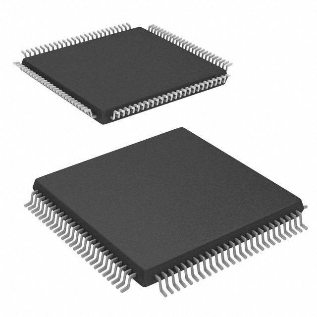
ICGOO电子元器件商城为您提供AT89LP52-20AU由Atmel设计生产,在icgoo商城现货销售,并且可以通过原厂、代理商等渠道进行代购。 AT89LP52-20AU价格参考¥13.81-¥13.81。AtmelAT89LP52-20AU封装/规格:嵌入式 - 微控制器, 8051 微控制器 IC 89LP 8-位 20MHz 8KB(8K x 8) 闪存 44-TQFP(10x10)。您可以下载AT89LP52-20AU参考资料、Datasheet数据手册功能说明书,资料中有AT89LP52-20AU 详细功能的应用电路图电压和使用方法及教程。
Microchip Technology的AT89LP52-20AU是一款基于80C51架构的低功耗、高性能嵌入式微控制器,广泛应用于各种嵌入式系统中。以下是该型号微控制器的一些典型应用场景:

 1. 工业自动化
AT89LP52-20AU可以用于工业自动化控制系统中,例如PLC(可编程逻辑控制器)和传感器接口模块。它具有丰富的I/O端口和定时器资源,能够实时采集和处理来自传感器的数据,并控制执行器的动作。其低功耗特性也适合长时间运行的工业设备。

 2. 智能家居
在智能家居领域,AT89LP52-20AU可用于智能照明、温控系统、安防监控等设备。它可以连接多种传感器(如温度、湿度、光敏传感器),并通过无线或有线通信模块与家庭网关进行数据交互,实现远程控制和自动化管理。

 3. 消费电子
该微控制器适用于各类消费电子产品,如遥控器、电子秤、玩具等。它具备良好的性价比和易用性,开发周期短,适合快速迭代的产品设计。此外,其内置的UART、SPI、I²C等通信接口方便与其他外设进行数据传输。

 4. 医疗设备
AT89LP52-20AU也可用于便携式医疗设备,如血糖仪、血压计等。这些设备通常要求高精度的数据采集和处理能力,而AT89LP52-20AU凭借其高效的处理器内核和丰富的外设接口,能够满足这类应用的需求。同时,其低功耗特性有助于延长电池寿命。

 5. 农业物联网
在农业物联网领域,AT89LP52-20AU可以作为环境监测节点的核心控制器,负责采集土壤湿度、空气温湿度、光照强度等数据,并通过无线通信模块将数据上传到云端平台。它还可以根据预设条件自动控制灌溉系统或温室通风设备。

总之,AT89LP52-20AU凭借其性能稳定、功耗低、成本适中的特点,在多个行业中都有着广泛的应用前景。
| 参数 | 数值 |
| 产品目录 | 集成电路 (IC)半导体 |
| 描述 | IC MCU 8BIT 8KB FLASH 44TQFP8位微控制器 -MCU Single-Cycle 8051 8K ISP Flash MCU |
| EEPROM容量 | - |
| 产品分类 | |
| I/O数 | 36 |
| 品牌 | Atmel |
| 产品手册 | |
| 产品图片 |
|
| rohs | 符合RoHS无铅 / 符合限制有害物质指令(RoHS)规范要求 |
| 产品系列 | 嵌入式处理器和控制器,微控制器 - MCU,8位微控制器 -MCU,Atmel AT89LP52-20AU89LP |
| 数据手册 | |
| 产品型号 | AT89LP52-20AU |
| PCN设计/规格 | |
| RAM容量 | 256 x 8 |
| 产品培训模块 | http://www.digikey.cn/PTM/IndividualPTM.page?site=cn&lang=zhs&ptm=26162http://www.digikey.cn/PTM/IndividualPTM.page?site=cn&lang=zhs&ptm=26159http://www.digikey.cn/PTM/IndividualPTM.page?site=cn&lang=zhs&ptm=26180 |
| 产品种类 | 8位微控制器 -MCU |
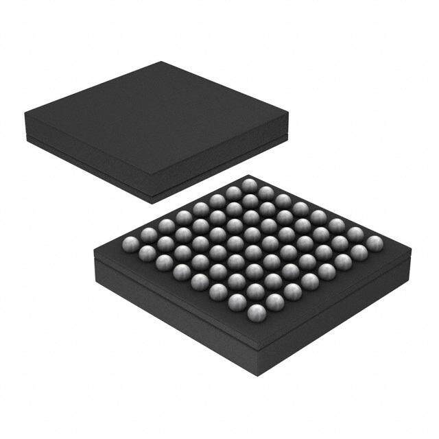
| 供应商器件封装 | 44-TQFP |
| 其它名称 | AT89LP5220AU |
| 包装 | 托盘 |
| 可编程输入/输出端数量 | 36 |
| 商标 | Atmel |
| 处理器系列 | AT89x |
| 外设 | 欠压检测/复位,POR,PWM,WDT |
| 安装风格 | SMD/SMT |
| 定时器数量 | 3 Timer |
| 封装 | Bulk |
| 封装/外壳 | 44-TQFP |
| 封装/箱体 | TQFP-44 |
| 工作温度 | -40°C ~ 85°C |
| 工作电源电压 | 2.7 V to 5.5 V |
| 工厂包装数量 | 160 |
| 振荡器类型 | 内部 |
| 接口类型 | Serial |
| 数据RAM大小 | 256 B |
| 数据Ram类型 | Flash |
| 数据总线宽度 | 8 bit |
| 数据转换器 | - |
| 最大工作温度 | + 85 C |
| 最大时钟频率 | 20 MHz |
| 标准包装 | 160 |
| 核心 | 8051 |
| 核心处理器 | 8051 |
| 核心尺寸 | 8-位 |
| 电压-电源(Vcc/Vdd) | 2.4 V ~ 5.5 V |
| 程序存储器大小 | 8 kB |
| 程序存储器类型 | Flash |
| 程序存储容量 | 8KB(8K x 8) |
| 输入/输出端数量 | 36 I/O |
| 连接性 | EBI/EMI, I²C, SPI, UART/USART |
| 速度 | 20MHz |


- 商务部:美国ITC正式对集成电路等产品启动337调查
- 曝三星4nm工艺存在良率问题 高通将骁龙8 Gen1或转产台积电
- 太阳诱电将投资9.5亿元在常州建新厂生产MLCC 预计2023年完工
- 英特尔发布欧洲新工厂建设计划 深化IDM 2.0 战略
- 台积电先进制程称霸业界 有大客户加持明年业绩稳了
- 达到5530亿美元!SIA预计今年全球半导体销售额将创下新高
- 英特尔拟将自动驾驶子公司Mobileye上市 估值或超500亿美元
- 三星加码芯片和SET,合并消费电子和移动部门,撤换高东真等 CEO
- 三星电子宣布重大人事变动 还合并消费电子和移动部门
- 海关总署:前11个月进口集成电路产品价值2.52万亿元 增长14.8%


PDF Datasheet 数据手册内容提取
Features • 8-bit Microcontroller Compatible with 8051 Products (cid:129) Enhanced 8051 Architecture – Single Clock Cycle per Byte Fetch – 12 Clock per Machine Cycle Compatibility Mode – Up to 20 MIPS Throughput at 20 MHz Clock Frequency – Fully Static Operation: 0 Hz to 20 MHz – On-chip 2-cycle Hardware Multiplier – 256 x 8 Internal RAM – External Data/Program Memory Interface 8-bit – Dual Data Pointers – 4-level Interrupt Priority Microcontroller (cid:129) Nonvolatile Program and Data Memory – 4K/8K Bytes of In-System Programmable (ISP) Flash Program Memory with 4K/8K – 256 Bytes of Flash Data Memory – 256-byte User Signature Array Bytes In-System – Endurance: 10,000 Write/Erase Cycles – Serial Interface for Program Downloading Programmable – 64-byte Fast Page Programming Mode – 3-level Program Memory Lock for Software Security Flash – In-Application Programming of Program Memory (cid:129) Peripheral Features – Three 16-bit Timer/Counters with Clock Out Modes AT89LP51 – Enhanced UART (cid:129) Automatic Address Recognition AT89LP52 (cid:129) Framing ErrorDetection (cid:129) SPI and TWI Emulation Modes – Programmable Watchdog Timer with Software Reset and Prescaler (cid:129) Special Microcontroller Features – Brown-out Detection and Power-on Reset with Power-off Flag – Selectable Polarity External Reset Pin – Low Power Idle and Power-down Modes – Interrupt Recovery from Power-down Mode – Internal 1.8432 MHz Auxiliary Oscillator (cid:129) I/O and Packages – Up to 36 Programmable I/O Lines – Green (Pb/Halide-free) Packages (cid:129) 40-lead PDIP (cid:129) 44-lead TQFP/PLCC (cid:129) 44-pad VQFN/MLF – Configurable Port Modes (per 8-bit port) (cid:129) Quasi-bidirectional (80C51 Style) (cid:129) Input-only (Tristate) (cid:129) Push-pull CMOS Output (cid:129) Open-drain (cid:129) Operating Conditions – 2.4V to 5.5V V Voltage Range CC – -40°C to 85°C Temperature Range – 0 to 20 MHz @ 2.4V–5.5V – 0 to 25 MHz @ 4.5V–5.5V 3709D–MICRO–12/11
1. Pin Configurations 1.1 40-lead PDIP (T2) P1.0 1 40 VCC (T2 EX) P1.1 2 39 P0.0 (AD0) P1.2 3 38 P0.1 (AD1) P1.3 4 37 P0.2 (AD2) P1.4 5 36 P0.3 (AD3) (MOSI) P1.5 6 35 P0.4 (AD4) (MISO) P1.6 7 34 P0.5 (AD5) (SCK) P1.7 8 33 P0.6 (AD6) RST 9 32 P0.7 (AD7) (RXD) P3.0 10 31 POL (TXD) P3.1 11 30 P4.2 (ALE) (INT0) P3.2 12 29 P4.3 (PSEN) (INT1) P3.3 13 28 P2.7 (A15) (T0) P3.4 14 27 P2.6 (A14) (T1) P3.5 15 26 P2.5 (A13) (WR) P3.6 16 25 P2.4 (A12) (RD) P3.7 17 24 P2.3 (A11) (XTAL2) P4.1 18 23 P2.2 (A10) (XTAL1) P4.0 19 22 P2.1 (A9) GND 20 21 P2.0 (A8) 1.2 44-lead TQFP X) E 0) 1) 2) 3) 2 2) D D D D T T A A A A 1.4 1.3 1.2 1.1 ( 1.0 ( NC CC 0.0 ( 0.1 ( 0.2 ( 0.3 ( P P P P P * V P P P P 4 3 2 1 0 9 8 7 6 5 4 4 4 4 4 4 3 3 3 3 3 3 (MOSI) P1.5 1 33 P0.4 (AD4) (MISO) P1.6 2 32 P0.5 (AD5) (SCK) P1.7 3 31 P0.6 (AD6) RST 4 30 P0.7 (AD7) (RXD) P3.0 5 29 POL *NC 6 28 *NC (TXD) P3.1 7 27 P4.4 (ALE) (INT0) P3.2 8 26 P4.5 (PSEN) (INT1) P3.3 9 25 P2.7 (A15) (T0) P3.4 10 24 P2.6 (A14) (T1) P3.5 11 23 P2.5 (A13) 2 3 4 5 6 7 8 9 0 1 2 1 1 1 1 1 1 1 1 2 2 2 6 7 7 6 D C 0 1 2 3 4 3. 3. 4. 4. N N 2. 2. 2. 2. 2. P P P P G * P P P P P R) D) 2) 1) 8) 9) 0) 1) 2) (W (R TAL TAL (A (A (A1 (A1 (A1 X X ( ( AT89LP51/52 2 3709D–MICRO–12/11
AT89LP51/52 1.3 44-lead PLCC X) E 0) 1) 2) 3) 2 2) D D D D T T A A A A 1.4 1.3 1.2 1.1 ( 1.0 ( NC CC 0.0 ( 0.1 ( 0.2 ( 0.3 ( P P P P P * V P P P P 6 5 4 3 2 1 4 3 2 1 0 4 4 4 4 4 (MOSI) P1.5 7 39 P0.4 (AD4) (MISO) P1.6 8 38 P0.5 (AD5) (SCK) P1.7 9 37 P0.6 (AD6) RST 10 36 P0.7 (AD7) (RXD) P3.0 11 35 POL *NC 12 34 *NC (TXD) P3.1 13 33 P4.4 (ALE) (INT0) P3.2 14 32 P4.5 (PSEN) (INT1) P3.3 15 31 P2.7 (A15) (T0) P3.4 16 30 P2.6 (A14) (T1) P3.5 17 29 P2.5 (A13) 8 9 0 1 2 3 4 5 6 7 8 1 1 2 2 2 2 2 2 2 2 2 6 7 7 6 D C 0 1 2 3 4 3. 3. 4. 4. N N 2. 2. 2. 2. 2. P P P P G * P P P P P R) D) 2) 1) 8) 9) 0) 1) 2) (W (R TAL TAL (A (A (A1 (A1 (A1 X X ( ( 1.4 44-pad VQFN/QFN/MLF X E 0 1 2 3 2 2 D D D D T T A A A A 1.4 1.3 1.2 1.1/ 1.0/ NC DD 0.0/ 0.1/ 0.2/ 0.3/ P P P P P * V P P P P 4 3 2 1 0 9 8 7 6 5 4 4 4 4 4 4 3 3 3 3 3 3 MOSI/P1.5 1 33 P0.4/AD4 MISO/P1.6 2 32 P0.5/AD5 SCK/P1.7 3 31 P0.6/AD6 RST 4 30 P0.7/AD7 RXD/P3.0 5 29 POL *NC 6 28 *NC TXD/P3.1 7 27 P4.4/ALE INT0/P3.2 8 26 P4.5/PSEN INT1/P3.3 9 25 P2.7/A15 T0/P3.4 10 24 P2.6/A14 T1/P3.5 11 23 P2.5/A13 NOTE: 12 13 14 15 16 17 18 19 20 21 22 Bottom pad should be 6 7 7 6 D C 0 1 2 3 4 soldered to ground 3. 3. 4. 4. N N 2. 2. 2. 2. 2. P P P P G * P P P P P R/ D/ 2/ 1/ 8/ 9/ 0/ 1/ 2/ W R AL AL A A A1 A1 A1 T T X X 3 3709D–MICRO–12/11
1.5 Pin Description Table 1-1. AT89LP51/52 Pin Description Pin Number TQFP PLCC PDIP VQFN Symbol Type Description I/O P1.5: I/O Port 1 bit 5. 1 7 6 1 P1.5 I/O MOSI: SPI master-out/slave-in. In UART SPI mode this pin is an output. During In- System Programming, this pin is an input. I/O P1.6: I/O Port 1 bit 6. 2 8 7 2 P1.6 I/O MISO: SPI master-in/slave-out. In UART SPI mode this pin is an input. During In- System Programming, this pin is an output. I/O P1.7: I/O Port 1 bit 7. 3 9 8 3 P1.7 I/O SCK: SPI Clock. In UART SPI mode this pin is an output. During In-System Programming, this pinis an input. RST: External Reset input (Reset polarity depends on POL pin. See “External Reset” I/O 4 10 9 4 RST on page 33.). The RST pin can output a pulse when the internal Watchdog reset is active. I/O P3.0: I/O Port 3 bit 0. 5 11 10 5 P3.0 I RXD: Serial Port Receiver Input. 6 12 6 NC Not internally connected I/O P3.1: I/O Port 3 bit 1. 7 13 11 7 P3.1 O TXD: Serial Port Transmitter Output. I/O P3.2: I/O Port 3 bit 2. 8 14 12 8 P3.2 I INT0: External Interrupt 0 Input or Timer 0 Gate Input. I/O P3.3: I/O Port 3 bit 3. 9 15 13 9 P3.3 I INT1: External Interrupt 1 Input or Timer 1 Gate Input I/O P3.4: I/O Port 3 bit 4. 10 16 14 10 P3.4 I/O T1: Timer/Counter 0 External input or output. I/O P3.5: I/O Port 3 bit 5. 11 17 15 1 P3.5 I/O T1: Timer/Counter 1 External input or output. I/O P3.6: I/O Port 3 bit 6. 12 18 16 12 P3.6 O WR: External memory interface Write Strobe (active-low). I/O P3.7: I/O Port 3 bit 7. 13 19 17 13 P3.7 O RD: External memory interface Read Strobe (active-low). I/O P4.7: I/O Port 4 bit 7. 14 20 18 14 P4.7 O XTAL2: Output from inverting oscillator amplifier. It may be used as a port pin if the internal RCoscillator or external clock is selected as the clock source. P4.6: I/O Port 4 bit 6. I/O XTAL1: Input to the inverting oscillator amplifier and internal clock generation circuits. 15 21 19 15 P4.6 I It may be used as a port pin if the internal RC oscillator is selected as the clock source. 16 22 20 16 GND I Ground 17 23 17 NC Not internally connected I/O P2.0: I/O Port 2 bit 0. 18 24 21 18 P2.0 O A8: External memory interface Address bit 8. I/O P2.1: I/O Port 2 bit 1. 19 25 22 19 P2.1 O A9: External memory interface Address bit 9. I/O P2.2: I/O Port 2 bit 2. 20 26 23 20 P2.1 O A10: External memory interface Address bit 10. AT89LP51/52 4 3709D–MICRO–12/11
AT89LP51/52 Table 1-1. AT89LP51/52 Pin Description Pin Number TQFP PLCC PDIP VQFN Symbol Type Description I/O P2.3: I/O Port 2 bit 3. 21 27 24 21 P2.3 O A11: External memory interface Address bit 11. I/O P2.4: I/O Port 2 bit 5. 22 28 25 22 P2.4 O A12: External memory interface Address bit 12. I/O P2.5: I/O Port 2 bit 5. 23 29 26 23 P2.5 O A13: External memory interface Address bit 13. I/O P2.6: I/O Port 2 bit 6. 24 30 27 24 P2.6 O A14: External memory interface Address bit 14. I/O P2.7: I/O Port 2 bit 7. 25 31 28 25 P2.7 O A15: External memory interface Address bit 15. I/O P4.5: I/O Port 4 bit 5. 26 32 29 26 P4.5 O PSEN: External memory interface Program Store Enable (active-low). I/O P4.4: I/O Port 4 bit 4. 27 33 30 27 P4.4 O ALE: External memory interface Address Latch Enable. 28 34 28 NC Not internally connected 29 35 31 29 POL I POL: Reset polarity (See “External Reset” on page 33.) I/O P0.7: I/O Port 0 bit 7. 30 36 32 30 P0.7 I/O AD7: External memory interface Address/Data bit 7. I/O P0.6: I/O Port 0 bit 6. 31 37 33 31 P0.6 I/O AD6: External memory interface Address/Data bit 6. I/O P0.5: I/O Port 0 bit 5. 32 38 34 32 P0.5 I/O AD5: External memory interface Address/Data bit 5. I/O P0.4: I/O Port 0 bit 4. 33 39 35 33 P0.4 I/O AD4: External memory interface Address/Data bit 4. I/O P0.3: I/O Port 0 bit 3. 34 40 36 34 P0.3 I/O AD3: External memory interface Address/Data bit 3. I/O P0.2: I/O Port 0 bit 2. 35 41 37 35 P0.2 I/O AD2: External memory interface Address/Data bit 2. I/O P0.1: I/O Port 0 bit 1. 36 42 38 36 P0.1 I/O AD1: External memory interface Address/Data bit 1. I/O P0.0: I/O Port 0 bit 0. 37 43 39 37 P0.0 I/O AD0: External memory interface Address/Data bit 0. 38 44 40 38 VDD I Supply Voltage 39 1 39 NC Not internally connected I/O P1.0: I/O Port 1 bit 0. 40 2 1 40 P1.0 I/O T2: Timer 2 External Input or Clock Output. I/O P1.1: I/O Port 1 bit 1. 41 3 2 41 P1.1 I T2EX: Timer 2 External Capture/Reload Input. 42 4 3 42 P1.2 I/O P1.2: I/O Port 1 bit 2. 43 5 4 43 P1.3 I/O P1.3: I/O Port 1 bit 3. 44 6 5 44 P1.4 I/O P1.4: I/O Port 1 bit 4. 5 3709D–MICRO–12/11
2. Overview The AT89LP51/52 is a low-power, high-performance CMOS 8-bit microcontroller with 4K/8K bytes of In-System Programmable Flash program memory and 256 bytes of Flash data memory. The device is manufactured using Atmel's high-density nonvolatile memory technology and is compatible with the industry-standard 80C52 instruction set. The AT89LP51/52 is built around an enhanced CPU core that can fetch a single byte from mem- ory every clock cycle. Inthe classic 8051 architecture, each fetch requires 6 clock cycles, forcing instructions to execute in 12, 24 or 48 clock cycles. In the AT89LP51/52 CPU, instructions need only 1 to 4 clock cycles providing 6 to 12 times more throughput than the standard 8051. Sev- enty percent of instructions need only as many clock cycles as they have bytes to execute, and most of the remaining instructions require only one additional clock. The enhanced CPU core is capable of 20 MIPS throughput whereas the classic 8051 CPU can deliver only 4MIPS at the same current consumption. Conversely, at the same throughput as the classic 8051, the new CPU core runs at a much lower speed and thereby greatly reducing power consumption and EMI. The AT89LP51/52 also includes a compatibility mode that will enable classic 12 clock per machine cycle operation for true timing compatibility with AT89S51/52. The AT89LP51/52 provides the following standard features: 4K/8K bytes of In-System ProgrammableFlash program memory, 256 bytes of Flash data memory, 256 bytes of RAM, up to 36 I/O lines, three 16-bit timer/counters, a programmable watchdog timer, a full-duplex serial port, an on-chip crystal oscillator, an internal 1.8432 MHz auxiliary oscillator, and a four-level, six-vector interrupt system. A block diagram is shown in Figure 2-1. Key Benefits: (cid:129) Full software and timing compatibility with AT89S52 means no changes to existing software, including fetching from external ROM or read/write from/to external RAM (cid:129) Disable compatibility mode to achieve on average 9 times more throughput at the same current consumption and frequency as AT89S52; or lower the clock frequency 9 times and achieve the same speed as AT89S52 but with more than 5 times less current consumption (cid:129) Save even more power and the cost of a quartz crystal by using the internal 1.8432 MHz RC oscillator, which is Vcc and temperature compensated well enough to ensure proper UART serial communications. Together with the built-in POR and the BOD circuits, you do not need any external components for AT89LP52 to provide the reset and clock functions (cid:129) All three timer/counters of the AT89LP51/52, Timer 0, Timer 1 and Timer 2, can be configured to toggle a port pin on overflow for clock/waveform generation. Unlike AT89S51, Timer 2 is also present on AT89LP51 (cid:129) The enhanced full-duplex UART of the AT89LP51/52 includes Framing Error Detection and Automatic Address Recognition. In addition, enhancements to Mode 0 allow hardware accelerated emulation of a master SPI or TWI (cid:129) Use In-Application Programming to alter the built-in 8K Flash program memory while executing the application, in effect making it possible to have programmable data tables embedded in the program code. Or use the 256-byte Flash Data memory for nonvolatile data storage (cid:129) Each 8-bit I/O port of the AT89LP51/52 can be independently configured in one of four operating modes. In quasi-bidirectional mode, the port operates as in the classic 8051. In input-only mode, the port is tristated. Push-pull output mode provides full CMOS drivers and open-drain mode provides just a pull-down. Unlike other 8051s, this allows Port 0 to operate with on-chip pull-ups if desired AT89LP51/52 6 3709D–MICRO–12/11
AT89LP51/52 2.1 Block Diagram Figure 2-1. AT89LP51/52 Block Diagram 4K/8K Bytes 256 Bytes 256 Bytes XRAM Flash Code Flash Data RAM Interface 8051 Single Cycle CPU with 12-cycle Compatibility Port 0 UART Configurable I/O Port 1 16-bit Timer 0 Configurable I/O 16-bit Timer 1 Port 2 16-bit Timer 2 Configurable I/O Port 3 Watchdog Configurable I/O Timer Port 4 POR Configurable I/O BOD Crystal or Configurable RC Auxiliary Resonator Oscillator Oscillator 2.2 System Configuration The AT89LP51/52 supports several system configuration options. Nonvolatile options are set through user fuses that must be programmed through the flash programming interface. Volatile options are controlled by software through individual bits of special function registers (SFRs). The AT89LP51/52 must be properly configured before correct operation can occur. 2.2.1 Fuse Options Table 2-1 lists the fusable options for the AT89LP51/52. These options maintain their state even when the device is powered off, but can only be changed with an external device programmer. For more information, see Section 17.7 “User Configuration Fuses” on page 86. 7 3709D–MICRO–12/11
Table 2-1. User Configuration Fuses Fuse Name Description Selects between the High Speed Crystal Oscillator, Low Speed Clock Source Crystal Oscillator, External Clock or Internal RC Oscillator for the source of the system clock. Start-up Time Selects time-out delay for the POR/BOD/PWD wake-up period. Configures the CPU in 12-clock Compatibility mode or single-cycle Compatibility Mode Fast mode In-System Programming Enable Enables or disables In-System Programming. User Signature Programming Enables or disables programming of User Signature array. Configures the default port state as input-only mode (tristated) or Tristate Ports quasi-bidirectional mode (weakly pulled high). In-Application Programming Enables or disables In-Application (self) Programming R1 Enable 2.2.2 Software Options Table 2-2 lists some important software configuration bits that affect operation at the system level. These can be changed by the application software but are set to their default values upon any reset. Most peripherals also have multipe configuration bits that are not listed here. Table 2-2. Important Software Configuration Bits Bit(s) SFR Location Description Configures the I/O mode of all pins of Port x to be nput-only, quasi- PxM0 PMOD bidirectional, push-pull output or open-drain. The default state is PxM1 controlled by the Default Port State fuse above CDV CLKREG.3-1 Selects the division ratio between the oscillator and the system clock 2-0 TPS CLKREG.7-4 Selects the division ratio between the system clock and the timers 3-0 DISALE AUXR.0 Enables/disables toggling of ALE Enables/disables access to on-chip memories that are mapped to the EXRAM AUXR.1 external data memory address space Selects the number of wait states when accessing external data WS AUXR.3-2 1-0 memory DMEN MEMCON.3 Enables/disables access to the on-chip flash data memory IAP MEMCON.7 Enbles/disables the self programming feature when the fuse allows 2.3 Comparison to AT89S51/52 The AT89LP51/52 is part of a family of devices with enhanced features that are fully binary com- patible with the 8051 instruction set. The AT89LP51/52 has two modes of operations, Compatibility mode and Fast mode. In Compatibility mode the instruction timing, peripheral behavior, SFR addresses, bit assignments and pin functions are identical to Atmel's existing AT89S51/52 product. Additional enhancements are transparent to the user and can be used if desired. Fast mode allows greater performance, but with some differences in behavior. The major enhancements from the AT89S51/52 are outlined in the following paragraphs and may be useful to users migrating to the AT89LP51/52 from older devices. A summary of the differences between Compatibility and Fast modes is given in Table 2-3 on page 10. See also the Applica- tion note “Migrating from AT89S52 to AT89LP52.” AT89LP51/52 8 3709D–MICRO–12/11
AT89LP51/52 2.3.1 Instruction Execution In Compatibility mode the AT89LP51/52 CPU uses the six-state machine cycle of the standard 8051 where instruction bytes are fetched every three system clock cycles. Execution times in this mode are identical to AT89S51/52. For greater performance the user can enable Fast mode by disabling the Compatibility fuse. In Fast mode the CPU fetches one code byte from memory every clock cycle instead of every three clock cycles. This greatly increases the throughput of the CPU. Each standard instruction executes in only 1 to 4 clock cycles. See “Instruction Set Summary” on page 75 for more details. Any software delay loops or instruction-based timing operations may need to be retuned to achieve the desired results in Fast mode. 2.3.2 System Clock By default in Compatibility mode the system clock frequency is divided by 2 from the externally supplied XTAL1 frequency for compatibility with standard 8051s (12 clocks per machine cycle). The System Clock Divider can scale the system clock versus the oscillator source (See Section 6.4 on page 31). The divide-by-2 can be disabled to operate in X2 mode (6 clocks per machine cycle) or the clock may be further divided to reduce the operating frequency. In Fast mode the clock divider defaults to divide by 1. The system clock source is selectable between the crystal oscillator, an externally driven clock and an internal 1.8432 MHz auxiliary oscillator. See “System Clock” on page 29 and “User Con- figuration Fuses” on page 86. 2.3.3 Reset The RST pin of the AT89LP51/52 has selectable polarity using the POL pin (formerly EA). When POL is high the RST pin is active high with a pull-down resistor and when POL is low the RST pin is active low with a pull-up resistor. For existing AT89S51/52 sockets where EA is tied to VDD, replacing AT89S51/52 with AT89LP51/52 will maintain the active high reset. Note that forcing external execution by tying EA low is not supported. The AT89LP51/52 includes an on-chip Power-On Reset and Brown-out Detector circuit that ensures that the device is reset from system power up. In most cases a RC startup circuit is not required on the RST pin, reducing system cost, and the RST pin may be left unconnected if a board-level reset is not present. 2.3.4 Timer/Counters A common prescaler is available to divide the time base for Timer 0, Timer 1, Timer 2 and the WDT. The TPS bits in the CLKREG SFR control the prescaler (Table 6-2 on page 31). In 3-0 Compatibility mode TPS defaults to 0101B, which causes the timers to count once every 3-0 machine cycle. The counting rate can be adjusted linearly from the system clock rate to 1/16 of the system clock rate by changing TPS . In Fast mode TPS defaults to 0000B, or the system 3-0 3-0 clock rate. TPS does not affect Timer 2 in Clock Out or Baud Generator modes. In Compatibility mode the sampling of the external Timer/Counter pins: T0, T1, T2 and T2EX; and the external interrupt pins, INT0 and INT1, is also controlled by the prescaler. In Fast mode these pins are always sampled at the system clock rate. Both Timer 0 and Timer 1 can toggle their respective counter pins, T0 and T1, when they over- flow by setting the output enable bits in TCONB. The Watchdog Timer includes a 7-bit prescaler for longer timeout periods than the AT89S51/52. Note that in Fast Mode the WDIDLE and DISRTO bits are located in WDTCON and not in AUXR. 9 3709D–MICRO–12/11
2.3.5 Interrupt Handling With the addition of the IPH register, the AT89LP51/52 provides four levels of interrupt priority for greater flexibility in handling multiple interrupts. Also, Fast mode allows for faster interrupt response due to the shorter instruction execution times. 2.3.6 Serial Port The timer prescaler increases the range of achievable baud rates when using Timer 1 to gener- ate the baud rate in UART Modes 1 or 3, including an increase in the maximum baud rate available in Compatibility mode. Additional features include automatic address recognition and framing error detection. The shift register mode (Mode 0) has been enhanced with more control of the polarity, phase and frequency of the clock and full-duplex operation. This allows emulation of master serial pheriperal (SPI) and two-wire (TWI) interfaces. 2.3.7 I/O Ports The P0, P1, P2 and P3 I/O ports of the AT89LP51/52 may be configured in four different modes. The default setting depends on the Tristate-Port User Fuse (See Section 17.7 on page 86). When the fuse is set all the I/O ports revert to input-only (tristated) mode at power-up or reset. When the fuse is not active, ports P1, P2 and P3 start in quasi-bidirectional mode and P0 starts in open-drain mode. P4 always operates in quasi-bidirectional mode. P0 can be configured to have internal pull-ups by placing it in quasi-bidirectional or output modes. This can reduce sys- tem cost by removing the need for external pull-ups on Port 0. The P4.4–P4.7 pins are additional I/Os that replace the normally dedicated ALE, PSEN, XTAL1 and XTAL2 pins of the AT89S51/52. These pins can be used as additional I/Os depending on the configuration of the clock and external memory. 2.3.8 Security The AT89LP51/52 does not support the extenal access pin (EA). Therefore it is not possible to execute from external program memory in address range 0000H–1FFFH. When the third Lockbit is enabled (Lock Mode 4) external program execution is disabled for all addresses above 1FFFH. This differs from AT89S51/52 where Lock Mode 4 prevents EA from being sampled low, but may still allow external execution at addresses outside the 8K internal space. 2.3.9 Programming The AT89LP51/52 supports a richer command set for In-System Programming (ISP). Existing AT89S51/52 programmers should be able to program the AT89LP51/52 in byte mode. In page mode the AT89LP51/52 only supports programming of a half-page of 64 bytes and therefore requires an extra address byte as compared to AT89S51/52. Furthermore the device signature is located at addresses 0000H, 0001H and 0003H instead of 0000H, 0100H and 0200H. Table 2-3. Compatibility Mode versus Fast Mode Summary Feature Compatibility Fast Instruction Fetch in System Clocks 3 1 Instruction Execution Time in System Clocks 6, 12, 18 or 24 1, 2, 3, 4 or 5 Default System Clock Divisor 2 1 Default Timer Prescaler Divisor 6 1 AT89LP51/52 10 3709D–MICRO–12/11
AT89LP51/52 Table 2-3. Compatibility Mode versus Fast Mode Summary Feature Compatibility Fast Pin Sampling Rate (INT0, INT1, T0, T1, T2, T2EX) Prescaler Rate System Clock Minimum RST input pulse in System Clocks 12 2 WDIDLE and DISRTO bit locations AUXR WDTCON 3. Memory Organization The AT89LP51/52 uses a Harvard Architecture with separate address spaces for program and data memory. The program memory has a regular linear address space with support for 64K bytes of directly addressable application code. The data memory has 256 bytes of internal RAM and 128 bytes of Special Function Register I/O space. The AT89LP51/52 supports up to 64K bytes of external data memory, with portions of the external data memory space implemented on chip as nonvolatile Flash data memory. External program memory is supported for addresses above 8K. The memory address spaces of the AT89LP51/52 are listed in Table 3-1. Table 3-1. AT89LP51/52 Memory Address Spaces Name Description Range DATA Directly addressable internal RAM 00H–7FH IDATA Indirectly addressable internal RAM and stack space 00H–FFH SFR Directly addressable I/O register space 80H–FFH FDATA On-chip nonvolatile Flash data memory 0000H–00FFH XDATA External data memory 0100H–FFFFH 0000H–0FFFH (AT89LP51) CODE On-chip nonvolatile Flash program memory 0000H–1FFFH (AT89LP52) 2000H–FFFFH (AT89LP51) XCODE External program memory 1000H–FFFFH (AT89LP52) SIG On-chip nonvolatile Flash signature array 0000H–01FFH 3.1 Program Memory The AT89LP51/52 contains 4K/8K bytes of on-chip In-System Programmable Flash memory for programstorage, plus support for up to 60K/56K bytes of external program memory. The Flash memory has an endurance of at least 10,000 write/erase cycles and a minimum data retention time of 10 years. The reset and interrupt vectors are located within the first 83 bytes of program memory (refer to Table 9-1 on page 38). Constant tables can be allocated within the entire 64K program memory address space for access by the MOVC instruction. A map of the AT89LP51/52 program memory is shown in Figure 3-1. 11 3709D–MICRO–12/11
Figure 3-1. Program Memory Map AT89LP51 AT89LP52 01FF 01FF User Signature Array User Signature Array 0100 0100 SIGEN=1 007F 007F Atmel Signature Array Atmel Signature Array 0000 0000 FFFF FFFF External Program External Program Memory Memory (XCODE: 60KB) (XCODE: 56KB) SIGEN=0 2000 1000 1FFF Internal Program 0FFF Internal Program Memory Memory (CODE: 8KB) (CODE: 4KB) 0000 0000 3.1.1 External Program Memory Interface The AT89LP51/52 uses the standard 8051 external program memory interface with the upper address on Port 2, the lower address and data in/out multiplexed on Port 0, and the ALE and PSEN strobes. Program memory addresses are always 16-bits wide, even though the actual amount of program memory used may be less than 64K byes. External program execution sacri- fices two full 8-bit ports, P0 and P2, to the function of addressing the program memory. Figure 3-2 shows a hardware configuration for accessing up to 64K bytes of external ROM using a 16-bit linear address. Port 0 serves as a multiplexed address/data bus to the ROM. The Address Latch Enable strobe (ALE) is used to latch the lower address byte into an external reg- ister so that Port 0 can be freed for data input/output. Port 2 provides the upper address byte throughout the operation. PSEN strobes the external memory. Figure 3-3 shows the timing of the external program memory interface. ALE is emitted at a con- stant rate of 1/3 of the system clock with a 1/3 duty cycle. PSEN is emitted at a similar rate, but with 50% duty cycle. The new address changes in the middle of the ALE pulse for latching on the falling edge and is tristated at the falling edge of PSEN. The instruction data is sampled from P0 and latched internally during the high phase of the clock prior to the rising edge of PSEN. This timing applies to both Compatibility and Fast modes. In Compatibility mode there is no dif- ference in instruction timing between internal and external execution. Figure 3-2. Executing from External Program Memory AT89LP EXTERNAL PROGRAM MEMORY P1 P0 INSTR. ALE LATCH ADDR P3 P2 PSEN OE AT89LP51/52 12 3709D–MICRO–12/11
AT89LP51/52 Figure 3-3. External Program Memory Fetches CLK ALE PSEN DATA DATA DATA SAMPLED SAMPLED SAMPLED P0 PCL PCL PCL OUT FLOAT OUT OUT P2 PCH OUT PCH OUT PCH OUT In order for Fast mode to fetch externally, two wait states must be inserted for every clock cycle, increasing the instruction execution time by a factor of 3. However, due to other optimizations, external Fast mode instructions may still be 1/4 to 1/2 faster than their Compatibility mode equiv- alents. Note that if ALE is allowed to toggle in Fast mode, there is a possibility that when the CPU jumps from internal to external execution a short pulse may occur on ALE as shown in Fig- ure 3-4. The setup time from the address to the falling edge of ALE remains the same. However, this behavior can be avoided by setting the DISALE bit prior to any jump above the 8K border. Figure 3-4. Internal/External Program Memory Boundary (Fast Mode) CLK SHORT ALE PULSE DISALE=0 ALE DISALE=1 INTERNAL EXECUTION EXTERNAL EXECUTION PSEN DATA SAMPLED P0 P0 SFR OUT PCL OUT FLOAT PCL OUT P2 P2 SFR OUT PCH OUT PCH OUT 3.1.2 SIG In addition to the 64K code space, the AT89LP51/52 also supports a 256-byte User Signature Array and a 128-byte Atmel Signature Array that are accessible by the CPU. The Atmel Signa- ture Array is initialized with the Device ID in the factory. The User Signature Array is available for user identification codes or constant parameter data. Data stored in the signature array is not secure. Security bits will disable writes to the array; however, reads by an external device pro- grammer are always allowed. In order to read from the signature arrays, the SIGEN bit (AUXR1.3) must be set (See Table 5-3 on page 28). While SIGEN is one, MOVC A,@A+DPTR will access the signature arrays. The User Signature Array is mapped from addresses 0100h to 01FFh and the Atmel Signature Array is mapped from addresses 0000h to 007Fh. SIGEN must be cleared before using MOVC to 13 3709D–MICRO–12/11
access the code memory. The User Signature Array may also be modified by the In-Application Programming interface. When IAP = 1 and SIGEN = 1, MOVX@DPTR instructions will access the array (See Section 3.4 on page 23). 3.2 Internal Data Memory The AT89LP51/52 contains 256 bytes of general SRAM data memory plus 128 bytes of I/O memory mapped into a single 8-bit address space. Access to the internal data memory does not require any configuration. The internal data memory has three address spaces: DATA, IDATA and SFR; as shown in Figure 3-5. Some portions of external data memory are also implemented internally. See “External Data Memory” below for more information. Figure 3-5. Internal Data Memory Map FFH FFH IDATA SFR ACCESSIBLE ACCESSIBLE UPPER 128 BY INDIRECT BY DIRECT ADDRESSING ADDRESSING ONLY 80H 80H 7FH DATA/IDATA ACCESSIBLE SPECIAL PORTS LOWER BY DIRECT FUNCTION STATUS AND 128 AND INDIRECT REGISTERS CONTROL BITS ADDRESSING TIMERS REGISTERS 0 STACK POINTER ACCUMULATOR (ETC.) 3.2.1 DATA The first 128 bytes of RAM are directly addressable by an 8-bit address (00H–7FH) included in the instruction. The lowest 32bytes of DATA memory are grouped into 4 banks of 8 registers each. The RS0 and RS1 bits (PSW.3 and PSW.4) select which register bank is in use. Instruc- tions using register addressing will only access the currently specified bank. The lower 128 bit addresses are also mapped into DATA addresses 20H—2FH. 3.2.2 IDATA The full 256 byte internal RAM can be indirectly addressed using the 8-bit pointers R0 and R1. The first 128 bytes of IDATA include the DATA space. The hardware stack is also located in the IDATA space. 3.2.3 SFR The upper 128 direct addresses (80H–FFH) access the I/O registers. I/O registers on AT89LP devices are referred to as Special Function Registers. The SFRs can only be accessed through direct addressing. All SFR locations are not implemented. See Section 4. for a listed of available SFRs. 3.3 External Data Memory AT89LP microcontrollers support a 16-bit external memory address space for up to 64K bytes of external data memory (XDATA). The external memory space is accessed with the MOVX instructions. Some internal data memory resources are mapped into portions of the external AT89LP51/52 14 3709D–MICRO–12/11
AT89LP51/52 address space as shown in Figure 3-6. These memory spaces may require configuration before the CPU can access them. The AT89LP51/52 includes 256 bytes of nonvolatile Flash data memory (FDATA). 3.3.1 XDATA The external data memory space can accommodate up to 64KB of external memory. The AT89LP51/52 uses the standard 8051 external data memory interface with the upper address byte on Port 2, the lower address byte and data in/out multiplexed on Port 0, and the ALE, RD and WR strobes. XDATA can be accessed with both 16-bit (MOVX @DPTR) and 8-bit (MOVX @Ri) addresses. See Section 3.3.3 on page 18 for more details of the external memory interface. Some internal data memory spaces are mapped into portions of the XDATA address space. In this case the lower address ranges will access internal resources instead of external memory. Addresses above the range implemented internally will default to XDATA. The AT89LP51/52 supports up to 63.75K or 56K bytes of external memory when using the internally mapped mem- ories. Setting the EXRAM bit (AUXR.1) to one will force all MOVX instructions to access the entire 64KB XDATA regardless of their address (See “AUXR – Auxiliary Control Register” on page 20). Figure 3-6. External Data Memory Map FFFF FFFF FFFF External Data (XDATA: 56KB) External Data External Data (XDATA: 64KB) (XDATA: 63.75KB) 2000 1FFF Flash Program 0100 (CODE: 8KB) 00FF Flash Data (FDATA: 256) 0000 EXRAM = 1 or EXRAM = 0 EXRAM = 0 DMEN = 0 DMEN = 1 DMEN = x IAP = 0 IAP = 0 IAP = 1 3.3.2 FDATA The Flash Data Memory is a portion of the external memory space implemented as an internal nonvolatile data memory. Flash Data Memory is enabled by setting the DMEN bit (MEMCON.3) to one. When IAP = 0 and DMEN = 1, the Flash Data Memory is mapped into the FDATA space, at the bottom of the external memory address space, from 0000H to 00FFH. (See Figure 3-6). MOVX instructions to this address range will access the internal nonvolatile memory. FDATA is 15 3709D–MICRO–12/11
not accessible while DMEN = 0. FDATA can be accessed only by 16-bit (MOVX @DPTR) addresses. MOVX@Ri instructions to the FDATA address range will access external memory. Addresses above the FDATA range are mapped to XDATA. 3.3.2.1 Write Protocol The FDATA address space accesses an internal nonvolatile data memory. This address space can be read just like EDATA by issuing a MOVXA,@DPTR; however, writes to FDATA require a more complex protocol and take several milliseconds to complete. For internal execution the AT89LP51/52 uses an idle-while-write architecture where the CPU is placed in an idle state while the write occurs. When the write completes, the CPU will continue executing with the instruction after the MOVX@DPTR,A instruction that started the write. All peripherals will continue to function during the write cycle; however, interrupts will not be ser- viced until the write completes. For external execution the AT89LP51/52 uses an execute-while-write architecture where the CPU continues to operate while the write occurs. The software should poll the state of the BUSY flag to determine when the write completes. Interrupts must be disabled during the write sequence as the CPU will not be able to vector to the internal interrupt table and care should be taken that the application does not jump to an internal address until the write completes. To enable write access to the nonvolatile data memory, the MWEN bit (MEMCON.4) must be set to one. When MWEN=1 and DMEN=1, MOVX@DPTR,A may be used to write to FDATA. FDATA uses flash memory with a page-based programming model. Flash data memory differs from traditional EEPROM data memory in the method of writing data. EEPROM generally can update a single byte with any value. Flash memory splits programming into write and erase operations. A Flash write can only program zeroes, i.e change ones into zeroes (1→0 ). Any ones in the write data are ignored. A Flash erase sets an entire page of data to ones so that all bytes become FFH. Therefore after an erase, each byte in the page can only be written once with any possible value. Bytes can be overwritten without an erase as long as only ones are changed into zeroes. However, if even a single bit needs updating from zero to one (0→1 ); then the contents of the page must first be saved, the entire page must be erased and the zero bits in all bytes (old and new data combined) must be written. Avoiding unnecessary page erases greatly improves the endurance of the memory.. The AT89LP51/52 includes 2 data pages of 128 bytes each. One or more bytes in a page may be written at one time. The AT89LP51/52 includes a temporary page buffer of 64 bytes, or half of a page. Because the page buffer is 64 bytes long, the maximum number of bytes written at one time is 64. Therefore, two write cycles are required to fill the entire 128-byte page, one for the low half page (00H–3FH) and one for the high half page (40H–7FH) as shown in Figure 3-7. Figure 3-7. Page Programming Structure 00 3F Page Buffer Data Memory Low Half Page High Half Page 00 3F 40 7F AT89LP51/52 16 3709D–MICRO–12/11
AT89LP51/52 The LDPG bit (MEMCON.5) allows multiple data bytes to be loaded to the temporary page buf- fer. While LDPG=1, MOVX@DPTR,A instructions will load data to the page buffer, but will not start a write sequence. Note that a previously loaded byte must not be reloaded prior to the write sequence. To write the half page into the memory, LDPG must first be cleared and then a MOVX@DPTR,A with the final data byte is issued. The address of the final MOVX determines which half page will be written. If a MOVX@DPTR,A instruction is issued while LDPG=0 with- out loading any previous bytes, only a single byte will be written. The page buffer is reset after each write operation. Figures 3-8 and Figure 3-9 on page 17 show the difference between byte writes and page writes. Figure 3-8. FDATA Byte Write DMEN MWEN LDPG IDLE t t WC WC MOVX Figure 3-9. FDATA Page Write DMEN MWEN LDPG IDLE t WC MOVX The auto-erase bit AERS (MEMCON.6) can be set to one to perform a page erase automatically at the beginning of any write sequence. The page erase will erase the entire page, i.e. both the low and high half pages. However, the write operation paired with the auto-erase can only pro- gram one of the half pages. A second write cycle without auto-erase is required to update the other half page. Frequently just a few bytes within a page must be updated while maintaining the state of the other bytes. There are two options for handling this situation that allow the Flash Data memory to emulate a traditional EEPROM memory. The simplest method is to copy the entire page into a buffer allocated in RAM, modify the desired byte locations in the RAM buffer, and then load and write back first the low half page (with auto-erase) and then the high half page to the Flash mem- ory. This option requires that at least one page size of RAM is available as a temporary buffer. The second option is to store only one half page in RAM. The unmodified bytes of the other page are loaded directly into the Flash memory’s temporary load buffer before loading the updated values of the modified bytes. For example, if just the low half page needs modification, the user must first store the high half page to RAM, followed by reading and loading the unaffected bytes of the low half page into the page buffer. Then the modified bytes of the low half page are stored 17 3709D–MICRO–12/11
to the page buffer before starting the auto-erase sequence. The stored value of the high half page must be written without auto-erase after the programming of the low half page completes. This method reduces the amount of RAM required; however, more software overhead is needed because the read-and-load-back routine must skip those bytes in the page that need to be updated in order to prevent those locations in the buffer from being loaded with the previous data, as this will block the new data from being loaded correctly. A write sequence will not occur if the Brown-out Detector is active. If a write currently in progress is interrupted by the BOD due to a low voltage condition, the ERR flag will be set. Table 3-2. MEMCON – Memory Control Register MEMCON = 96H Reset Value = 0000 0XXXB Not Bit Addressable IAP AERS LDPG MWEN DMEN ERR BUSY WRTINH Bit 7 6 5 4 3 2 1 0 Symbol Function IAP In-Application Programming Enable. When IAP = 1 and the IAP Fuse is enabled, programming of the CODE/SIG space is enabled and MOVX @DPTR instructions will access CODE/SIG instead of EDATA or FDATA. Clear IAP to disable programming of CODE/SIG and allow access to EDATA and FDATA. AERS Auto-Erase Enable. Set to perform an auto-erase of a Flash memory page (CODE, SIG or FDATA) during the next write sequence. Clear to perform write without erase. LDPG Load Page Enable. Set to this bit to load multiple bytes to the temporary page buffer. Byte locations may not be loaded more than once before a write. LDPG must be cleared before writing. MWEN Memory Write Enable. Set to enable programming of a nonvolatile memory location (CODE, SIG or FDATA). Clear to disable programming of all nonvolatile memories. DMEN Data Memory Enable. Set to enable nonvolatile data memory and map it into the FDATA space. Clear to disable nonvolatile data memory. ERR Error Flag. Set by hardware if an error occurred during the last programming sequence due to a brownout condition (low voltage on VDD). Must be cleared by software. BUSY Busy Flag. WRTINH Write Inhibit Flag. Cleared by hardware when the voltage on VDD has fallen below the minimum programming voltage. Set by hardware when the voltage on VDD is above the minimum programming voltage. 3.3.3 External Data Memory Interface The AT89LP51/52 uses the standard 8051 external data memory interface with the upper address on Port 2, the lower address and data in/out multiplexed on Port 0, and the ALE, RD and WR strobes. The interface may be used in two different configurations depending on which type of MOVX instruction is used to access XDATA. Figure 3-10 shows a hardware configuration for accessing up to 64K bytes of external RAM using a 16-bit linear address. Port 0 serves as a multiplexed address/data bus to the RAM. The Address Latch Enable strobe (ALE) is used to latch the lower address byte into an external reg- ister so that Port 0 can be freed for data input/output. Port 2 provides the upper address byte throughout the operation. The MOVX@DPTR instructions use Linear Address mode. AT89LP51/52 18 3709D–MICRO–12/11
AT89LP51/52 Figure 3-10. External Data Memory 16-bit Linear Address Mode AT89LP EXTERNAL DATA MEMORY P1 P0 DATA ALE LATCH ADDR P2 P3 RD WR WE OE Figure 3-11 shows a hardware configuration for accessing 256-byte blocks of external RAM using an 8-bit paged address. Port 0 serves as a multiplexed address/data bus to the RAM. The ALE strobe is used to latch the address byte into an external register so that Port 0 can be freed for data input/output. The Port 2 I/O lines (or other ports) can provide control lines to page the memory; however, this operation is not handled automatically by hardware. The software appli- cation must change the Port 2 register when appropriate to access different pages. The MOVX@Ri instructions use Paged Address mode. Figure 3-11. External Data Memory 8-bit Paged Address Mode AT89LP EXTERNAL DATA MEMORY P1 P0 DATA ALE LATCH ADDR P3 P2 RD I/O PAGE WR WE OE BITS Note that prior to using the external memory interface, WR (P3.6) and RD (P3.7) must be config- ured as outputs. See Section 10.1 “Port Configuration” on page 41. P0 and P2 are configured automatically to push-pull output mode when outputting address or data and P0 is automatically tristated when inputting data regardless of the port configuration. The Port 0 configuration will determine the idle state of Port 0 when not accessing the external memory. Figure 3-12 and Figure 3-13 show examples of external data memory write and read cycles, respectively. The address on P0 and P2 is stable at the falling edge of ALE. The idle state of ALE is controlled by DISALE (AUXR.0). When DISALE=0 the ALE toggles at a constant rate when not accessing external memory. When DISALE=1 the ALE is weakly pulled high. DISALE must be one in order to use P4.4 as a general-purpose I/O. The WS bits in AUXR can extended the RD and WR strobes by 1, 2 or 3 cycles as shown in Figures 3-16, 3-17 and 3-18. If a longer strobe is required, the application can scale the system clock with the clock divider to meet the requirements (SeeSection 6.4 on page 31). 19 3709D–MICRO–12/11
Table 3-3. AUXR – Auxiliary Control Register AUXR = 8EH Reset Value = xxx0 0000B Not Bit Addressable DISRTO(1) – – – WDIDLE(1) WS0 EXRAM DISALE WS1(2) Bit 7 6 5 4 3 2 1 0 Symbol Function WDT Disable during Idle(1). When WDIDLE=0 the WDT continues to count in Idle mode. When WDIDLE=1 the WDT WDIDLE halts counting in Idle mode. Disable Reset Output(1). When DISTRO=0 the reset pin is driven to the same level as POL when the WDT resets. DISRTO When DISRTO=1 the reset pin is input only. WS[1-0] Wait State Select. Determines the number of wait states inserted into external memory accesses. WS1(2) WS0 Wait States RD / WR Strobe Width ALE to RD / WR Setup 0 0 0 1 x t (Fast); 3 x t (Compatibility) 1 x t (Fast); 1.5 x t (Compatibility) CYC CYC CYC CYC 0 1 1 2 x t (Fast); 15 x t (Compatibility) 1 x t (Fast); 1.5 x t (Compatibility) CYC CYC CYC CYC 1 0 2 2 x t (Fast) 2 x t (Fast) CYC CYC 1 1 3 3 x t (Fast) 2 x t (Fast) CYC CYC External RAM Enable. When EXRAM=0, MOVX instructions can access the internally mapped portions of the address EXRAM space. Accesses to addresses above internally mapped memory will access external memory. Set EXRAM=1 to bypass the internal memory and map the entire address space to external memory. ALE Disable. When DISALE=0 the ALE pulse is active at 1/3 of the system clock frequency in Compatibility mode and DISALE 1/2 of the system clock frequency in Fast mode. When DISALES=1 the ALE is inactive (high) unless an external memory access occurs. DISALE must be set to use P4.4 as a general I/O. Notes: 1. AUXR.4 and AUXR.3 function as WDIDLE and DISRTO only in Compatibility mode. In Fast mode these bits are located in WDTCON. 2. WS1 is only available in Fast mode. WS1 is forced to 0 in Compatibility mode. Figure 3-12. Fast Mode External Data Memory Write Cycle (WS=00B) S1 S2 S3 S4 CLK ALE WR P0 P0 SFR DPL or Ri OUT DATA OUT P0 SFR P2 P2 SFR DPH or P2 OUT P2 SFR AT89LP51/52 20 3709D–MICRO–12/11
AT89LP51/52 Figure 3-13. Fast Mode External Data Memory Read Cycle (WS=00B) S1 S2 S3 S4 CLK ALE RD DATA SAMPLED P0 P0 SFR DPL or Ri OUT P0 SFR FLOAT P2 P2 SFR DPH or P2 OUT P2 SFR Figure 3-14. Compatibility Mode External Data Memory Write Cycle (WS0=0) S4 S5 S6 S1 S2 S3 S4 S5 CLK ALE WR P0 P0 SFR DPL or Ri DATA OUT PCL or OUT P0 SFR P2 PCH or DPH or P2 OUT PCH or P2 SFR P2 SFR Figure 3-15. Compatibility Mode External Data Memory Read Cycle (WS0=0) S4 S5 S6 S1 S2 S3 S4 S5 CLK ALE RD DATA SAMPLED P0 P0 SFR DPL or Ri PCL or OUT FLOAT P0 SFR P2 PCH or DPH or P2 OUT PCH or P2 SFR P2 SFR 21 3709D–MICRO–12/11
Figure 3-16. MOVX with One Wait State (WS=01B) S1 S2 S3 W1 S4 CLK ALE P2 P2 SFR DPH or P2 OUT P2 SFR WR P0 P0 SFR DPL OUT DATA OUT P0 SFR RD FLOAT P0 P0 SFR DPL OUT P0 SFR Figure 3-17. MOVX with Two Wait States (WS=10B) S1 S2 S3 W1 W2 S4 CLK ALE P2 P2 SFR DPH or P2 OUT P2 SFR WR P0 P0 SFR DPL OUT DATA OUT P0 SFR RD FLOAT P0 P0 SFR DPL OUT P0 SFR Figure 3-18. MOVX with Three Wait States (WS=11B) S1 S2 S3 W1 W2 W3 S4 CLK ALE P2 P2 SFR DPH or P2 OUT P2 SFR WR P0 P0 SFR DPL OUT DATA OUT P0 SFR RD FLOAT P0 P0 SFR DPL OUT P0 SFR AT89LP51/52 22 3709D–MICRO–12/11
AT89LP51/52 3.4 In-Application Programming (IAP) The AT89LP51/52 supports In-Application Programming (IAP), allowing the program memory to be modified during execution. IAP can be used to modify the user application on the fly or to use program memory for nonvolatile data storage. The same page structure write protocol for FDATA also applies to IAP (See Section 3.3.2.1 “Write Protocol” on page 16). The CPU is always placed in idle while modifying the program memory. When the write completes, the CPU will continue executing with the instruction after the MOVX@DPTR,A instruction that started the write. To enable access to the program memory, the IAP bit (MEMCON.7) must be set to one and the IAP User Fuse must be enabled. The IAP User Fuse can disable all IAP operations. When this fuse is disabled, the IAP bit will be forced to 0. While IAP is enabled, all MOVX@DPTR instruc- tions will access the CODE space instead of EDATA/FDATA/XDATA. IAP also allows reprogramming of the User Signature Array when SIGEN = 1. The IAP access settings are sum- marized in Table 3-4 and Table 3-5. Table 3-4. IAP Access Settings for AT89LP52 IAP SIGEN DMEN MOVX @DPTR MOVC @DPTR CODE (0000–1FFFH) 0 0 0 XDATA (0000–FFFFH) XCODE (2000–FFFFH) FDATA (0000–00FFH) CODE (0000–1FFFH) 0 0 1 XDATA (0100–FFFFH) XCODE (2000–FFFFH) 0 1 0 XDATA (0000–FFFFH) SIG (0000–01FFH) FDATA (0000–00FFH) 0 1 1 SIG (0000–01FFH) XDATA (0100–FFFFH) CODE (0000–1FFFH) CODE (0000–1FFFH) 1 0 X XDATA (2000–FFFFH) XCODE (2000–FFFFH) SIG (0000–01FFH) 1 1 X SIG (0000–01FFH) XDATA (2000–FFFFH) Table 3-5. IAP Access Settings for AT89LP51 IAP SIGEN DMEN MOVX @DPTR MOVC @DPTR CODE (0000–0FFFH) 0 0 0 XDATA (0000–FFFFH) XCODE (1000–FFFFH) FDATA (0000–00FFH) CODE (0000–0FFFH) 0 0 1 XDATA (0100–FFFFH) XCODE (1000–FFFFH) 0 1 0 XDATA (0000–FFFFH) SIG (0000–01FFH) FDATA (0000–00FFH) 0 1 1 SIG (0000–01FFH) XDATA (0100–FFFFH) CODE (0000–0FFFH) CODE (0000–0FFFH) 1 0 X XDATA (1000–FFFFH) XCODE (1000–FFFFH) SIG (0000–01FFH) 1 1 X SIG (0000–01FFH) XDATA (1000–FFFFH) Note: When In-Application programming is not required, it is recommended that the IAP User Fuse be disabled. 23 3709D–MICRO–12/11
4. Special Function Registers A map of the on-chip memory area called the Special Function Register (SFR) space is shown in Table 4-1. Note that not all of the addresses are occupied, and unoccupied addresses may not be imple- mented on the chip. Read accesses to these addresses will in general return random data, and write accesses will have an indeterminate effect. User software should not write to these unlisted locations, since they may be used in future products to invoke new features. Table 4-1. AT89LP51/52 SFR Map and Reset Values 8 9 A B C D E F 0F8H 0FFH B 0F0H 0F7H 00000000 0E8H 0EFH ACC 0E0H 0E7H 00000000 0D8H 0DFH PSW 0D0H 0D7H 00000000 0C8H T2CON T2MOD RCAP2L RCAP2H TL2 TH2 0CFH 00000000 00000000 0000000 00000000 0000000 00000000 P4 PMOD 0C0H 0C7H 11111111 (2) IP SADEN 0B8H 0BFH xx000000 00000000 P3 IPH 0B0H 0B7H 11111111 xx000000 IE SADDR 0A8H 0AFH 0x000000 00000000 0A0H P2 AUXR1 WDTRST WDTCON 0A7H 11111111 000000x0 (write-only) 00000xx0 SCON SBUF 98H 9FH 00000000 xxxxxxxx P1 TCONB MEMCON 90H 97H 11111111 000xxxxx 000000xx TCON TMOD TL0 TL1 TH0 TH1 AUXR CLKREG 88H 8FH 00000000 00000000 00000000 00000000 00000000 00000000 00000000 (3) P0 SP DP0L DP0H DP1L DP1H PCON 80H 87H 11111111 00000111 00000000 00000000 00000000 00000000 000x0000 0 1 2 3 4 5 6 7 Notes: 1. All SFRs in the left-most column are bit-addressable. 2. Reset value is 01010101B when Tristate-Port Fuse is enabled and 00000011B when disabled. 3. Reset value is 01010010B when Compatibility mode is enabled and 00000000B when disabled. AT89LP51/52 24 3709D–MICRO–12/11
AT89LP51/52 5. Enhanced CPU The AT89LP51/52 uses an enhanced 8051 CPU that runs at 6 to 12 times the speed of standard 8051 devices (or 3 to 6 times the speed of X2 8051 devices). The increase in performance is due to two factors. First, the CPU fetches one instruction byte from the code memory every clock cycle. Second, the CPU uses a simple two-stage pipeline to fetch and execute instructions in parallel. This basic pipelining concept allows the CPU to obtain up to 1 MIPS per MHz. The AT89LP51/52 also has a Compatibility mode that preserves the 12-clock machine cycle of stan- dard 8051s like the AT89S51/52. 5.1 Fast Mode Fast (Single-Cycle) mode must be enabled by clearing the Compatibility User Fuse. (See “User Configuration Fuses” on page 86.) In this mode one instruction byte is fetched every system clock cycle. The 8051 instruction set allows for instructions of variable length from 1 to 3 bytes. In a single-clock-per-byte-fetch system this means each instruction takes at least as many clocks as it has bytes to execute. The majority of instructions in the AT89LP51/52 follow this rule: the instruction execution time in system clock cycles equals the number of bytes per instruction, with a fewexceptions. Branches and Calls require an additional cycle to compute the target address and some other complex instructions require multiple cycles. See “Instruction Set Summary” on page 75. for more detailed information on individual instructions. Example of Fast mode instructions are shown in Figure 5-1. Note that Fast mode instructions take three times as long to execute if they are fetched from external program memory. Figure 5-1. Instruction Execution Sequences in Fast Mode CLK READ NEXT OPCODE S1 (A) 1-byte, 1-cycle instruction, e.g. INC A READ OPERAND READ NEXT OPCODE S1 S2 (B) 2-byte, 2-cycle instruction, e.g. ADD A, #data READ NEXT OPCODE S1 S2 (C) 1-byte, 2-cycle instruction, e.g. INC DPTR READ NEXT OPCODE S1 S2 S3 S4 ADDR DATA ACCESS EXTERNAL MEMORY (D) MOVX (1-byte, 4-cycle) 25 3709D–MICRO–12/11
5.2 Compatibility Mode Compatibility (12-Clock) mode is enabled by default from the factory or by setting the Compati- bility User Fuse. In Compatibility mode instruction bytes are fetched every three system clock cycles and the CPU operates with 6-state machine cycles and a divide-by-2 system clock for 12 oscillator periods per machine cycle. Standard instructions execute in1, 2 or 4 machine cycles. Instruction timing in this mode is compatible with standard 8051s such as the AT89S51/52. Compatibility mode can be used to preserve the execution profiles of legacy applications. For a summary of differences between Fast and Compatibility modes see Table 2-3 on page 10. Examples of Compatibility mode instructions are shown in Figure 5-2. Figure 5-2. Instruction Execution Sequences in Compatibility Mode SS11 SS22 SS33 SS44 SS55 SS66 SS11 SS22 SS33 SS44 SS55 SS66 SS11 CCLLKK AALLEE RREEAADD OOPPCCOODDEE RREEAADD NNEEXXTT OOPPCCOODDEE RREEAADD NNEEXXTT OOPPCCOODDEE AAGGAAIINN ((DDIISSCCAARRDD)) SS11 SS22 SS33 SS44 SS55 SS66 (A) 1-byte, 1-cycle instruction, e.g., INC AA RREEAADD OOPPCCOODDEE RREEAADD 22NNDD RREEAADD NNEEXXTT OOPPCCOODDEE BBYYTTEE SS11 SS22 SS33 SS44 SS55 SS66 ((BB)) 22--bbyyttee,, 11--ccyyccllee iinnssttrruuccttiioonn,, ee..gg..,, AADDDD AA,, ##ddaattaa RREEAADD NNEEXXTT RREEAADD OOPPCCOODDEE OOPPCCOODDEE ((DDIISSCCAARRDD)) RREEAADD NNEEXXTT OOPPCCOODDEE AAGGAAIINN SS11 SS22 SS33 SS44 SS55 SS66 SS11 SS22 SS33 SS44 SS55 SS66 ((CC)) 11--bbyyttee,, 22--ccyyccllee iinnssttrruuccttiioonn,, ee..gg..,, IINNCC DDPPTTRR RREEAADD RREEAADD NNEEXXTT NNOO NNOO RREEAADD NNEEXXTT OOPPCCOODDEE OOPPCCOODDEE ((DDIISSCCAARRDD)) FFEETTCCHH NNOO FFEETTCCHH OOPPCCOODDEE ((MMOOVVXX)) AALLEE AAGGAAIINN SS11 SS22 SS33 SS44 SS55 SS66 SS11 SS22 SS33 SS44 SS55 SS66 ((DD)) MMOOVVXX ((11--bbyyttee,, 22--ccyyccllee)) AADDDDRR DDAATA AACCCCEESSSS EEXXTTEERRNNAALL MMEEMMOORRY 5.3 Enhanced Dual Data Pointers The AT89LP51/52 provides two 16-bit data pointers: DPTR0 formed by the register pair DPOL and DPOH (82H an 83H), and DPTR1 formed by the register pair DP1L and DP1H (84H and 85H). The data pointers are used by several instructions to access the program or data memo- ries. The Data Pointer Configuration Register (AUXR1) controls operation of the dual data pointers (Table 5-3 on page 28). The DPS bit in AUXR1 selects which data pointer is currently referenced by instructions including the DPTR operand. Each data pointer may be accessed at its respective SFR addresses regardless of the DPS value. The AT89LP51/52 provides two methods for fast context switching of the data pointers: AT89LP51/52 26 3709D–MICRO–12/11
AT89LP51/52 (cid:129) Bit 2 of AUXR1 is hard-wired as a logic 0. The DPS bit may be toggled (to switch data pointers) simply by incrementing the AUXR1 register, without altering other bits in the register unintentionally. This is the preferred method when only a single data pointer will be used at one time. EX: INC AUXR1 ; Toggle DPS (cid:129) In some cases, both data pointers must be used simultaneously. To prevent frequent toggling of DPS, the AT89LP51/52 supports a prefix notation for selecting the opposite data pointer per instruction. All DPTR instructions, with the exception of JMP@A+DPTR, when prefixed with an 0A5H opcode will use the inverse value of DPS (DPS) to select the data pointer. Some assemblers may support this operation by using the /DPTR operand. For example, the following code performs a block copy within EDATA: MOV AUXR1, #00H ; DPS = 0 MOV DPTR, #SRC ; load source address to dptr0 MOV /DPTR, #DST ; load destination address to dptr1 MOV R7, #BLKSIZE ; number of bytes to copy COPY: MOVX A, @DPTR ; read source (dptr0) INC DPTR ; next src (dptr0+1) MOVX @/DPTR, A ; write destination (dptr1) INC /DPTR ; next dst (dptr1+1) DJNZ R7, COPY For assemblers that do not support this notation, the 0A5H prefix must be declared in-line: EX: DB 0A5H INC DPTR ; equivalent to INC /DPTR A summary of data pointer instructions with fast context switching is listed inTable 5-1. Table 5-1. Data Pointer Instructions Operation Instruction DPS = 0 DPS = 1 JMP @A+DPTR JMP @A+DPTR0 JMP @A+DPTR1 MOV DPTR, #data16 MOV DPTR0, #data16 MOV DPTR1, #data16 MOV /DPTR, #data16 MOV DPTR1, #data16 MOV DPTR0, #data16 INC DPTR INC DPTR0 INC DPTR1 INC /DPTR INC DPTR1 INC DPTR0 MOVC A,@A+DPTR MOVC A,@A+DPTR0 MOVC A,@A+DPTR1 MOVC A,@A+/DPTR MOVC A,@A+DPTR1 MOVC A,@A+DPTR0 MOVX A,@DPTR MOVX A,@DPTR0 MOVX A,@DPTR1 MOVX A,@/DPTR MOVX A,@DPTR1 MOVX A,@DPTR0 MOVX @DPTR, A MOVX @DPTR0, A MOVX @DPTR1, A MOVX @/DPTR, A MOVX @DPTR1, A MOVX @DPTR0, A 5.3.1 Data Pointer Update The Dual Data Pointers on the AT89LP51/52 include two features that control how the data pointers are updated. The data pointer decrement bits, DPD1 and DPD0 in AUXR1, configure the INC DPTR instruction to act as DEC DPTR. The resulting operation will depend on DPS as shown in Table 5-2. These bits also control the direction of auto-updates during MOVC and MOVX. 27 3709D–MICRO–12/11
Table 5-2. Data Pointer Decrement Behavior Equivalent Operation for INC DPTR and INC /DPTR DPS = 0 DPS = 1 DPD1 DPD0 INC DPTR INC /DPTR INC DPTR INC /DPTR 0 0 INC DPTR0 INC DPTR1 INC DPTR1 INC DPTR0 0 1 DEC DPTR0 INC DPTR1 INC DPTR1 DEC DPTR0 1 0 INC DPTR0 DEC DPTR1 DEC DPTR1 INC DPTR0 1 1 DEC DPTR0 DEC DPTR1 DEC DPTR1 DEC DPTR0 Table 5-3. AUXR1 – Data Pointer Configuration Register AUXR1 = A2H Reset Value = 0000 00X0B Not Bit Addressable DPU1 DPU0 DPD1 DPD0 SIGEN 0 – DPS Bit 7 6 5 4 3 2 1 0 Symbol Function DPU1 Data Pointer 1 Update. When set, MOVX @DPTR and MOVC @DPTR instructions that use DPTR1 will also update DPTR1 based on DPD1. If DPD1 = 0 the operation is post-increment and if DPD1 = 1 the operation is post-decrement. When DPU1 = 0, DPTR1 is not updated. DPU0 Data Pointer 0 Update. When set, MOVX @DPTR and MOVC @DPTR instructions that use DPTR0 will also update DPTR0 based on DPD0. If DPD0 = 0 the operation is post-increment and if DPD0 = 1 the operation is post-decrement. When DPU0 = 0, DPTR0 is not updated. DPD1 Data Pointer 1 Decrement. When set, INC DPTR instructions targeted to DPTR1 will decrement DPTR1. When cleared, INC DPTR instructions will increment DPTR1. DPD1 also determines the direction of auto-update for DPTR1 when DPU1=1. DPD0 Data Pointer 0 Decrement. When set, INC DPTR instructions targeted to DPTR0 will decrement DPTR0. When cleared, INC DPTR instructions will increment DPTR0. DPD0 also determines the direction of auto-update for DPTR0 when DPU0=1. SIGEN Signature Enable. When SIGEN = 1 all MOVC @DPTR instructions and all IAP accesses will target the signature array memory. When SIGEN = 0, all MOVC and IAP accesses target CODE memory. DPS Data Pointer Select. DPS selects the active data pointer for instructions that reference DPTR. When DPS = 0, DPTR will target DPTR0 and /DPTR will target DPTR1. When DPS = 1, DPTR will target DPTR1 and /DPTR will target DPTR0. The data pointer update bits, DPU1 and DPU0, allow MOVX @DPTR and MOVC @DPTR instructions to update the selected data pointer automatically in a post-increment or post-decre- ment fashion. The direction of update depends on the DPD1 and DPD0 bits as shown in Table 5-4. These bits can be used to make block copy routines more efficient. Table 5-4. Data Pointer Auto-Update Update Operation for MOVX and MOVC (DPU1 = 1 & DPU0 = 1) DPS = 0 DPS = 1 DPD1 DPD0 DPTR /DPTR DPTR /DPTR 0 0 DPTR0++ DPTR1++ DPTR1++ DPTR0++ 0 1 DPTR0-- DPTR1++ DPTR1++ DPTR0-- 1 0 DPTR0++ DPTR1-- DPTR1-- DPTR0++ 1 1 DPTR0-- DPTR1-- DPTR1-- DPTR0-- AT89LP51/52 28 3709D–MICRO–12/11
AT89LP51/52 6. System Clock The system clock is generated directly from one of three selectable clock sources. The three sources are the on-chip crystal oscillator, external clock source, and internal RC oscillator. A dia- gram of the clock subsystem is shown in Figure 6-1. The on-chip crystal oscillator may also be configured for low or high power operation. The clock source is selected by the Clock Source User Fuses as shown in Table 6-1. See “User Configuration Fuses” on page 86. By default, in Fast mode no internal clock division is used to generate the CPU clock from the system clock. In Compatibility mode the default is to divide the oscillator output by two. The system clock divider may be used to prescale the system clock with other values. The choice of clock source also affects the start-up time after a POR, BOD or Power-down event (See “Reset” on page 32 or “Power-down Mode” on page 35) Figure 6-1. Clock Subsystem Diagram CLOCK FUSES INTERNAL 1.8432MHz CLKIRC 0 OSC CLKEXT 1 5-BIT CLOCK CLKXTAL 2 DIVIDER XTAL1 3 6 2 2 4 8 1 3 osc /osc/osc/osc/osc/osc K K K K K K L L L L L L C C C C C C XTAL2 TPS3-0 CDV2-0 0 1 2 3 4 5 Timer 0 4-BIT Timer 1 PRESCALER Timer 2 Watchdog SYSTEM CLOCK (CLKSYS) Table 6-1. Clock Source Settings Clock Source Clock Source Fuse 1 Fuse 0 Selected Clock Source 1 1 High Power Crystal Oscillator (f > 12 MHz) 1 0 Low Power Crystal Oscillator (f ≤ 12 MHz) 0 1 External Clock on XTAL1 0 0 Internal 1.8432 MHz Auxiliary Oscillator 6.1 Crystal Oscillator When enabled, the internal inverting oscillator amplifier is connected between XTAL1 and XTAL2 for connection to an external quartz crystal or ceramic resonator. The oscillator may operate in either high-power or low-power mode. Low-speed mode is intended for crystals of 12 MHz or less and consumes less power than the higher speed mode. The configuration as shown in Figure 6-2 applies for both high and low power oscillators. Note that in some cases, external capacitors C1 and C2 may NOT be required due to the on-chip capacitance of the XTAL1 and XTAL2 inputs (approximately 10 pF each). When using the crystal oscillator, P4.6 and P4.7 will have their inputs and outputs disabled. Also, XTAL2 in crystal oscillator mode should not be used to directly drive a board-level clock without a buffer. 29 3709D–MICRO–12/11
An optional 5 MΩ on-chip resistor can be connected between XTAL1 and GND. This resistor can improve the startup characteristics of the oscillator especially at higher frequencies. The resistor can be enabled/disabled with the R1 User Fuse (See “User Configuration Fuses” on page 86.) Figure 6-2. Crystal Oscillator Connections C2 ~10 pF C1 R1 ~10 pF ~5 MΩ Note: 1. C1, C2 = 5 pF ± 5pF for Crystals = 5 pF ± 5pF for Ceramic Resonators 6.2 External Clock Source The external clock option disables the oscillator amplifier and allows XTAL1 to be driven directly by an external clock source as shown in Figure 6-3. XTAL2 may be left unconnected, used as general purpose I/O P4.7, or configured to output a divided version of the system clock. Figure 6-3. External Clock Drive Configuration NC GPIO XTA L2 (P4.7) EXTERNAL OSCILLAT O R XTA L1 (P4.6) SIGNAL GND 6.3 Internal RC Oscillator The AT89LP51/52 has an Internal Auxiliary oscillator tuned to 1.8432 MHz ±2.0%. When enabled astheclock source, XTAL1 and XTAL2 may be used as P4.6 and P4.7 respectively. AT89LP51/52 30 3709D–MICRO–12/11
AT89LP51/52 6.4 System Clock Divider The CDV bits in CLKREG allow the system clock to be divided down from the selected clock 2-0 source by powers of 2. The clock divider provides users with a greater frequency range when using the Internal Oscillator. For example, to achieve a 230.4 kHz system frequency when using the RC oscillator, CDV should be set to 011B for divide-by-8 operation. The divider can also 2-0 be used to reduce power consumption by decreasing the operational frequency during non-criti- cal periods. The resulting system frequency is given by the following equation: f f = ---O----S---C--- SYS CDV 2 where f is the frequency of the selected clock source. The clock divider will prescale the clock OSC for the CPU and all peripherals. The value of CDV may be changed at any time without interrupt- ing normal execution. Changes to CDV are synchronized such that the system clock will not pass through intermediate frequencies. When CDV is updated, the new frequency will take affect within a maximum period of 32 x t . OSC In Compatibility mode the divider defaults to divide-by-2 and and in Fast mode it defaults to no division. Table 6-2. CLKREG – Clock Control Register CLKREG = 8FH Reset Value = 0?0? 00?0B Not Bit Addressable TPS3 TPS2 TPS1 TPS0 CDV2 CDV1 CDV0 — Bit 7 6 5 4 3 2 1 0 Symbol Function TPS[3-0] Timer Prescaler. The Timer Prescaler selects the time base for Timer 0, Timer 1, Timer 2 and the Watchdog Timer. The prescaler is implemented as a 4-bit binary down counter. When the counter reaches zero it is reloaded with the value stored in the TPS bits to give a division ratio between 1 and 16. By default the timers will count every clock cycle in Fast mode (TPS = 0000B) and every six cycles in Compatibility mode (TPS = 0101B). System Clock Division. Determines the frequency of the system clock relative to the oscillator clock source. CDIV2 CDIV1 CDIV0 System Clock Frequency 0 0 0 f /1 OSC 0 0 1 f /2 OSC 0 1 0 f /4 OSC CDV[2-0] 0 1 1 f /8 OSC 1 0 0 f /16 OSC 1 0 1 f /32 OSC 1 1 0 Reserved 1 1 1 Reserved Note: The reset value of CLKREG is 0000000B in Fast mode and 01010010B in Compatibility mode. 31 3709D–MICRO–12/11
7. Reset During reset, all I/O Registers are set to their initial values, the port pins are set to their default mode, and the program starts execution from the Reset Vector, 0000H. The AT89LP51/52 has five sources of reset: power-on reset, brown-out reset, external reset, watchdog reset, and soft- ware reset. 7.1 Power-on Reset A Power-on Reset (POR) is generated by an on-chip detection circuit. The detection level V POR is nominally 1.4V. The POR is activated whenever V is below the detection level. The POR cir- DD cuit can be used to trigger the start-up reset or to detect a major supply voltage failure. The POR circuit ensures that the device is reset from power-on. A power-on sequence is shown in Figure 7-1. When V reaches the Power-on Reset threshold voltage V , an initialization sequence DD POR lasting t is started. When the initialization sequence completes, the start-up timer determines POR how long the device is kept in POR after V rise. The start-up timer does not begin counting DD until after V reaches the Brown-out Detector (BOD) threshold voltage V . The POR signal is DD BOD activated again, without any delay, when V falls below the POR threshold level. A Power-on DD Reset (i.e. a cold reset) will set the POF flag in PCON. The internally generated reset can be extended beyond the power-on period by holding the RST pin active longer than the time-out. Figure 7-1. Power-on Reset Sequence V BOD VDD VPOR t SUT Time-out tPOR POL (POL Tied to VCC) RST (RST Tied to GND) Internal Reset RST (RST Controlled Externally) VIL Internal t RHD Reset Note: t is approximately 143 µs ± 5%. POR The start-up timer delay is user-configurable with the Start-up Time User Fuses and depends on the clock source (Table 7-1). The Start-Up Time fuses also control the length of the start-up time after a Brown-out Reset or when waking up from Power-down during internally timed mode. The start-up delay should be selected to provide enough settling time for V and the selected clock DD source. The device operating environment (supply voltage, frequency, temperature, etc.) must meet the minimum system requirements before the device exits reset and starts normal opera- tion. The RST pin may be held active externally until these conditions are met. AT89LP51/52 32 3709D–MICRO–12/11
AT89LP51/52 Table 7-1. Start-up Timer Settings SUT Fuse 1 SUT Fuse 0 Clock Source t (± 5%) µs SUT Internal RC/External Clock 16 0 0 Crystal Oscillator 1024 Internal RC/External Clock 512 0 1 Crystal Oscillator 2048 Internal RC/External Clock 1024 1 0 Crystal Oscillator 4096 Internal RC/External Clock 4096 1 1 Crystal Oscillator 16384 7.2 Brown-out Reset The AT89LP51/52 has an on-chip Brown-out Detection (BOD) circuit for monitoring the V level DD during operation by comparing it to a fixed trigger level. The trigger level V for the BOD is BOD nominally 2.0V. The purpose of the BOD is to ensure that if V fails or dips while executing at DD speed, the system will gracefully enter reset without the possibility of errors induced by incorrect execution. A BOD sequence is shown in Figure 7-2. When V decreases to a value below the DD trigger level V , the internal reset is immediately activated. When V increases above the BOD DD trigger level plus about 200mV of hysteresis, the start-up timer releases the internal reset after the specified time-out period has expired (Table 7-1). Figure 7-2. Brown-out Detector Reset V VBOD DD VPOR tSUT Time-out Internal Reset The AT89LP51/52 allows for a wide V operating range. The on-chip BOD may not be suffi- DD cient to prevent incorrect execution if V is lower than the minimum required V range, such BOD DD as when a 5.0V supply is coupled with high frequency operation. In such cases an external Brown-out Reset circuit connected to the RST pin may be required. 7.3 External Reset The RST pin of the AT89LP51/52 can function as either an active-low reset input or as an active- high reset input. The polarity of the RST pin is selectable using the POL pin (formerly EA). When POL is high the RST pin is active high with an on-chip pull-down resistor tied to GND. When POL is low the RST pin is active low with an on-chip pull-up resistor tied to V . The RST pin DD structure is shown in Figure 7-3. In Compatibility mode the reset pin is sampled every six clock cycles and must be held active for at least twelve clock cycles to trigger the internal reset. In Fast mode the reset pin is sampled every clock cycle and must be held active for at least two clock cycles to trigger the internal reset. 33 3709D–MICRO–12/11
The AT89LP51/52 includes an on-chip Power-On Reset and Brown-out Detector circuit that ensures that the device is reset from system power up. In most cases a RC startup circuit is not required on the RST pin, reducing system cost, and the RST pin may be left unconnected if a board-level reset is not present. Note: RST also serves as the In-System Programming (ISP) enable. ISP is enabled when the external reset pin is held active. When ISP is disabled by fuse, ISP may only be entered by pulling RST active during power-up. If this behavior is necessary, it is recommended to use an active-low reset so that ISP can be entered by shorting RST to GND at power-up. Figure 7-3. Reset Pin Structure VCC POL = 1 VCC POL = 0 DISRTO WDT Reset Internal Reset RST RST Internal Reset DISRTO WDT Reset 7.4 Watchdog Reset When the Watchdog times out, it will generate a reset pulse lasting 49 clock cycles. By default this pulse is also output on the RST pin. To disable the RST output the DISRTO bit in AUXR (Compatibility mode) or WDTCON (Fast mode) must be set to one. Watchdog reset will set the WDTOVF flag in WDTCON. To prevent a Watchdog reset, the watchdog reset sequence 1EH/E1H must be written to WDTRST before the Watchdog times out. See “Programmable Watchdog Timer” on page 73. for details on the operation of the Watchdog. 7.5 Software Reset The CPU may generate a 49-clock cycle reset pulse by writing the software reset sequence 5AH/A5H to the WDRST register. A software reset will set the SWRST bit in WDTCON. See “Software Reset” on page 73 for more information on software reset. Writing any sequences other than 5AH/A5H or 1EH/E1H to WDTRST will generate an immediate reset and set both WDTOVF and SWRST to flag an error. Software reset will also drive the RST pin active unless DISRTO is set. 8. Power Saving Modes The AT89LP51/52 supports two different power-reducing modes: Idle and Power-down. These modes are accessed through the PCON register. Additional steps may be required to achieve the lowest possible power consumption while using these modes. 8.1 Idle Mode Setting the IDL bit in PCON enters idle mode. Idle mode halts the internal CPU clock. The CPU state is preserved in its entirety, including the RAM, stack pointer, program counter, program status word, and accumulator. The Port pins hold the logic states they had at the time that Idle was activated. Idle mode leaves the peripherals running in order to allow them to wake up the AT89LP51/52 34 3709D–MICRO–12/11
AT89LP51/52 CPU when an interrupt is generated. The timer and UART peripherals continue to function dur- ing Idle. If these functions are not needed during idle, they should be explicitly disabled by clearing the appropriate control bits in their respective SFRs. The watchdog may be selectively enabled or disabled during Idle by setting/clearing the WDIDLE bit. The Brown-out Detector is always active during Idle. Any enabled interrupt source or reset may terminate Idle mode. When exiting Idle mode with an interrupt, the interrupt will immediately be serviced, and following RETI the next instruction to be executed will be the one following the instruction that put the device into Idle. The power consumption during Idle mode can be further reduced by prescaling down the system clock using the System Clock Divider (Section 6.4 on page 31). Be aware that the clock divider will affect all peripheral functions and baud rates may need to be adjusted to maintain their rate with the new clock frequency. . Table 8-1. PCON – Power Control Register PCON = 87H Reset Value = 000X 0000B Not Bit Addressable SMOD1 SMOD0 PWDEX POF GF1 GF0 PD IDL Bit 7 6 5 4 3 2 1 0 Symbol Function SMOD1 Double Baud Rate bit. Doubles the baud rate of the UART in Modes 1, 2, or 3. SMOD0 Frame Error Select. When SMOD0 = 1, SCON.7 is SM0. When SMOD0 = 1, SCON.7 is FE. Note that FE will be set after a frame error regardless of the state of SMOD0. PWDEX Power-down Exit Mode. When PWDEX = 0, wake up from Power-down is externally controlled. When PWDEX = 1, wake up from Power-down is internally timed. POF Power Off Flag. POF is set to “1” during power up (i.e. cold reset). It can be set or reset under software control and is not affected by RST or BOD (i.e. warm resets). GF1, GF0 General-purpose Flags PD Power-down bit. Setting this bit activates power-down operation. The PD bit is cleared automatically by hardware when waking up from power-down. IDL Idle Mode bit. Setting this bit activates Idle mode operation. The IDL bit is cleared automatically by hardware when waking up from idle 8.2 Power-down Mode Setting the Power-down (PD) bit in PCON enters Power-down mode. Power-down mode stops the oscillator, disables the BOD and powers down the Flash memory in order to minimize power consumption. Only the power-on circuitry will continue to draw power during Power-down. Dur- ing Power-down, the power supply voltage may be reduced to the RAM keep-alive voltage. The RAM contents will be retained, but the SFR contents are not guaranteed once V has been DD reduced. Power-down may be exited by external reset, power-on reset, or certain enabled interrupts. 35 3709D–MICRO–12/11
8.2.1 Interrupt Recovery from Power-down Two external interrupt sources may be configured to terminate Power-down mode: external interrupts INT0 (P3.2) and INT1 (P3.3). To wake up by external interrupt INT0 or INT1, that inter- rupt must be enabled by setting EX0 or EX1 in IE and must be configured for level-sensitive operation by clearing IT0 or IT1. When terminating Power-down by an interrupt, two different wake-up modes are available. When PWDEX in PCON is one, the wake-up period is internally timed as shown in Figure 8-1. At the falling edge on the interrupt pin, Power-down is exited, the oscillator is restarted, and an internal timer begins counting. The internal clock will not be allowed to propagate to the CPU until after the timer has timed out. After the time-out period the interrupt service routine will begin. The time-out period is controlled by the Start-up Timer Fuses (see Table 7-1 on page 33). The interrupt pin need not remain low for the entire time-out period. Figure 8-1. Interrupt Recovery from Power-down (PWDEX = 1) PWD XTAL1 tSUT INT1 Internal Clock When PWDEX = “0”, the wake-up period is controlled externally by the interrupt. Again, at the falling edge on the interrupt pin, power-down is exited and the oscillator is restarted. However, the internal clock will not propagate until the rising edge of the interrupt pin as shown in Figure 8- 2. The interrupt pin should be held low long enough for the selected clock source to stabilize. After the rising edge on the pin the interrupt service routine will be executed. Figure 8-2. Interrupt Recovery from Power-down (PWDEX = 0) PWD XTAL1 INT1 Internal Clock 8.2.2 Reset Recovery from Power-down The wake-up from Power-down through an external reset is similar to the interrupt with PWDEX= “1”. At the rising edge of RST, Power-down is exited, the oscillator is restarted, and an internal timer begins counting as shown in Figure 8-3. The internal clock will not be allowed to propagate to the CPU until after the timer has timed out. The time-out period is controlled by the Start-up Timer Fuses. (See Table 7-1 on page 33). If RST returns low before the time-out, a two clock cycle internal reset is generated when the internal clock restarts. Otherwise, the device will remain in reset until RST is brought low. AT89LP51/52 36 3709D–MICRO–12/11
AT89LP51/52 Figure 8-3. Reset Recovery from Power-down (POL=1) PWD XTAL1 tSUT RST Internal Clock Internal Reset 8.3 Reducing Power Consumption Several possibilities need consideration when trying to reduce the power consumption in an 8051-based system. Generally, Idle or Power-down mode should be used as often as possible. All unneeded functions should be disabled. The System Clock Divider can scale down the oper- ating frequency during periods of low demand. The ALE output can be disabled by setting DISALE in AUXR, thereby also reducing EMI. 9. Interrupts The AT89LP51/52 provides 6 interrupt sources: two external interrupts, three timer interrupts, and a serial port interrupt. These interrupts and the system reset each have a separate program vector at the start of the program memory space. Each interrupt source can be individually enabled or disabled by setting or clearing a bit in the interrupt enable register IE. The IE register also contains a global disable bit, EA, which disables all interrupts. Each interrupt source can be individually programmed to one of four priority levels by setting or clearing bits in the interrupt priority registers IP and IPH. IP holds the low order priority bits and IPH holds the high priority bits for each interrupt. An interrupt service routine in progress can be interrupted by a higher priority interrupt, but not by another interrupt of the same or lower priority. The highest priority interrupt cannot be interrupted by any other interrupt source. If two requests of different priority levels are pending at the end of an instruction, the request of higher priority level is serviced. If requests of the same priority level are pending at the end of an instruction, an internal polling sequence determines which request is serviced. The polling sequence is based on the vector address; an interrupt with a lower vector address has higher priority than an inter- rupt with a higher vector address. Note that the polling sequence is only used to resolve pending requests of the same priority level. The External Interrupts INT0 and INT1 can each be either level-activated or edge-activated, depending on bits IT0 and IT1 in Register TCON. The flags that actually generate these inter- rupts are the IE0 and IE1 bits in TCON. When the service routine is vectored to, hardware clears the flag that generated an external interrupt only if the interrupt was edge-activated. If the inter- rupt was level activated, then the external requesting source (rather than the on-chip hardware) controls the request flag. The Timer 0 and Timer 1 Interrupts are generated by TF0 and TF1, which are set by a rollover in their respective Timer/Counter registers (except for Timer 0 in Mode 3). When a timer interrupt is generated, the on-chip hardware clears the flag that generated it when the service routine is 37 3709D–MICRO–12/11
vectored to. The Timer 2 Interrupt is generated by a logic OR of bits TF2 and EXF2 in register T2CON. Neither of these flags is cleared by hardware when the CPU vectors to the service rou- tine. The service routine normally must determine whether TF2 or EXF2 generated the interrupt and that bit must be cleared by software. The Serial Port Interrupt is generated by the logic OR of RI and TI in SCON. Neither of these flags is cleared by hardware when the CPU vectors to the service routine. The service routine normally must determine whether RI or TI generated the interrupt and that bit must be cleared by software. All of the bits that generate interrupts can be set or cleared by software, with the same result as though they had been set or cleared by hardware. That is, interrupts can be generated and pending interrupts can be canceled in software. Table 9-1. Interrupt Vector Addresses Interrupt Source Vector Address System Reset RST or POR or BOD 0000H External Interrupt 0 IE0 0003H Timer 0 Overflow TF0 000BH External Interrupt 1 IE1 0013H Timer 1 Overflow TF1 001BH Serial Port Interrupt RI or TI 0023H Timer 2 Interrupt TF2 or EXF2 002BH 9.1 Interrupt Response Time The interrupt flags may be set by their hardware in any clock cycle. The interrupt controller polls the flags in the last clock cycle of the instruction in progress. If one of the flags was set in the preceding cycle, the polling cycle will find it and the interrupt system will generate an LCALL to the appropriate service routine as the next instruction, provided that the interrupt is not blocked by any of the following conditions: an interrupt of equal or higher priority level is already in prog- ress; the instruction in progress is RETI or any write to the IE, IP or IPH registers; the CPU is currently forced into idle by an IAP or FDATA write. Each of these conditions will block the gen- eration of the LCALL to the interrupt service routine. The second condition ensures that if the instruction in progress is RETI or any access to IE, IP or IPH, then at least one more instruction will be executed before any interrupt is vectored to. The polling cycle is repeated at the last cycle of each instruction, and the values polled are the values that were present at the previous clock cycle. If an active interrupt flag is not being serviced because of one of the above conditions and is no longer active when the blocking conditionis removed, the denied interrupt will not be ser- viced. In other words, the fact that the interrupt flag was once active but not serviced is not remembered. Every polling cycle is new. If a request is active and conditions are met for it to be acknowledged, a hardware subroutine call to the requested service routine will be the next instruction executed. The call itself takes four cycles. Thus, a minimum of five complete clock cycles elapsed between activation of an interrupt request and the beginning of execution of the first instruction of the service routine. A longer response time results if the request is blocked by one of the previously listed conditions. If an interrupt of equal or higher priority level is already in progress, the additional wait time depends on the nature of the other interrupt's service routine. If the instruction in progress is not in its final clock cycle, the additional wait time cannot be more than 4 cycles, since the longest AT89LP51/52 38 3709D–MICRO–12/11
AT89LP51/52 instruction is 5 cycles long. If the instruction in progress is RETI, the additional wait time cannot be more than 9 cycles (a maximum of 4 more cycles to complete the instruction in progress, plus a maximum of 5 cycles to complete the next instruction). Thus, in a single-interrupt system, the response time is always more than 5 clock cycles and less than 14 clock cycles. See Figure 9-1 and Figure 9-2. Figure 9-1. Minimum Interrupt Response Time (Fast Mode) Clock Cycles 1 5 INT0 IE0 Ack. Instruction Cur. Instr. LCALL 1st ISR Instr. Figure 9-2. Maximum Interrupt Response Time (Fast Mode) Clock Cycles 1 5 10 14 INT0 IE0 Ack. Instruction RETI MOVX @/DPTR, A LCALL 1st ISR Instr. Figure 9-3. Minimum Interrupt Response Time (Compatibility Mode) Clock Cycles 1 14 INT0 Ack. IE0 Instruction LCALL ISR Figure 9-4. Maximum Interrupt Response Time (Compatibility Mode) Clock Cycles 1 13 37 49 INT0 IE0 Ack. Instruction RETI MUL AB LCALL ISR 39 3709D–MICRO–12/11
Table 9-2. IE – Interrupt Enable Register IE = A8H Reset Value = 0000 0000B Bit Addressable EA – ET2 ES ET1 EX1 ET0 EX0 Bit 7 6 5 4 3 2 1 0 Symbol Function Global enable/disable. All interrupts are disabled when EA = 0. When EA = 1, each interrupt source is enabled/disabled by setting EA /clearing its own enable bit. ET2 Timer 2 Interrupt Enable ES Serial Port Interrupt Enable ET1 Timer 1 Interrupt Enable EX1 External Interrupt 1 Enable ET0 Timer 0 Interrupt Enable EX0 External Interrupt 0 Enable Table 9-3. IP – Interrupt Priority Register IP = B8H Reset Value = 0000 0000B Bit Addressable – – PT2 PS PT1 PX1 PT0 PX0 Bit 7 6 5 4 3 2 1 0 Symbol Function PT2 Timer 2 Interrupt Priority Low PS Serial Port Interrupt Priority Low PT1 Timer 1 Interrupt Priority Low PX1 External Interrupt 1 Priority Low PT0 Timer 0 Interrupt Priority Low PX0 External Interrupt 0 Priority Low Table 9-4. IPH – Interrupt Priority High Register IPH = B7H Reset Value = 0000 0000B Not Bit Addressable – – PT2H PSH PT1H PX1H PT0H PX0H Bit 7 6 5 4 3 2 1 0 Symbol Function PT2H Timer 2 Interrupt Priority High PSH Serial Port Interrupt Priority High PT1H Timer 1 Interrupt Priority High PX1H External Interrupt 1 Priority High PT0H Timer 0 Interrupt Priority High PX0H External Interrupt 0 Priority High AT89LP51/52 40 3709D–MICRO–12/11
AT89LP51/52 10. I/O Ports The AT89LP51/52 can be configured for between 32 and 36 I/O pins. The exact number of I/O pins available depends on the clock, external memory and package type as shown in Table 10- 1. Table 10-1. I/O Pin Configurations Number of I/O Clock Source External Program Access External Data Access Pins Yes (RD+WR) 14 Yes (PSEN+ALE+P0+P2) No 16 External Crystal or Resonator Yes (ALE+RD+WR+P0) 31 No No 34 Yes (RD+WR) 15 Yes (PSEN+ALE+P0+P2) No 17 External Clock Yes (ALE+RD+WR+P0) 32 No No 35 Yes (RD+WR) 16 Yes (PSEN+ALE+P0+P2) Internal RC No 18 Oscillator Yes (ALE+RD+WR+P0) 33 No No 36 10.1 Port Configuration Each 8-bit port on the AT89LP51/52 may be configured in one of four modes: quasi-bidirectional (standard 8051 port outputs), push-pull output, open-drain output, or input-only. Port modes may be assigned in software on a port-by-port basis as shown in Table 10-2 using the PMOD register listed in Table 10-3. The Tristate-Port User Fuse determines the default state of the port pins (See “User Configuration Fuses” on page 86). When the fuse is enabled, all port pins default to input-only mode after reset. When the fuse is disabled, all port pins on P1, P2 and P3 default to quasi-bidirectional mode after reset and are weakly pulled high. P0 is set to Open-drain mode. P4 always operates in quasi-bidirectional mode. Each port pin also has a Schmitt-triggered input for improved input noise rejection. During Power-down all the Schmitt-triggered inputs are disabled with the exception of P3.2 (INT0), P3.3 (INT1), RST, P4.6 (XTAL1) and P4.7 (XTAL2). Therefore, P3.2, P3.3, P4.6 and P4.7 should not be left floating during Power-down. .Table 10-2. Configuration Modes for Port x PxM0 PxM1 Port Mode 0 0 Quasi-bidirectional 0 1 Push-pull Output 1 0 Input Only (High Impedance) 1 1 Open-Drain Output 41 3709D–MICRO–12/11
. Table 10-3. PMOD – Port Mode Register PMOD = C1H Reset Value = 0000 0011B Not Bit Addressable P3M1 P3M0 P2M1 P2M0 P1M1 P1M0 P0M1 P0M0 Bit 7 6 5 4 3 2 1 0 Symbol Function P3M Port 3 Configuration Mode 1-0 P2M Port 2 Configuration Mode 1-0 P1M Port 1 Configuration Mode 1-0 P0M Port 0 Configuration Mode 1-0 10.1.1 Quasi-bidirectional Output Port pins in quasi-bidirectional output mode function similar to standard 8051 port pins. A Quasi- bidirectional port can be used both as an input and output without the need to reconfigure the port. This is possible because when the port outputs a logic high, it is weakly driven, allowing an external device to pull the pin low. When the pin is driven low, it is driven strongly and able to sink a large current. There are three pull-up transistors in the quasi-bidirectional output that serve different purposes. One of these pull-ups, called the “very weak” pull-up, is turned on whenever the port latch for the pin contains a logic “1”. This very weak pull-up sources a very small current that will pull the pin high if it is left floating. When the pin is pulled low externally this pull-up will always source some current. A second pull-up, called the “weak” pull-up, is turned on when the port latch for the pin contains a logic “1” and the pin itself is also at a logic “1” level. This pull-up provides the primary source current for a quasi-bidirectional pin that is outputting a “1”. If this pin is pulled low by an external device, this weak pull-up turns off, and only the very weak pull-up remains on. In order to pull the pin low under these conditions, the external device has to sink enough current to overpower the weak pull-up and pull the port pin below its input threshold voltage. The third pull-up is referred to as the “strong” pull-up. This pull-up is used to speed up low-to- high transitions on a quasi-bidirectional port pin when the port latch changes from a logic “0” to a logic “1”. When this occurs, the strong pull-up turns on for one CPU clock, quickly pulling the port pin high. The quasi-bidirectional port configuration is shown in Figure 10-1. 10.1.2 Input-only Mode The input only port configuration is shown in Figure 10-2. The output drivers are tristated. The input includes a Schmitt-triggered input for improved input noise rejection. The input circuitry of P3.2, P3.3, P4.6 and P4.7 is not disabled during Power-down (see Figure 10-3) and therefore these pins should not be left floating during Power-down when configured in this mode. Input-only mode can reduce power consumption for low-level inputs over quasi-bidirectional mode because the “very weak” pull-up is turned off and only very small leakage current in the sub microamp range is present. AT89LP51/52 42 3709D–MICRO–12/11
AT89LP51/52 Figure 10-1. Quasi-bidirectional Output V V V CC CC CC 1 Clo ck Del ay (D Flip-Flop) Strong Ve r y We a k We a k Po r t Pin Fr om Po r t Register Input Data PWD Figure 10-2. Input Only Input Po r t Data Pin PWD Figure 10-3. Input Circuit for P3.2, P3.3, P4.6 and P4.7 Input Port Data Pin 10.1.3 Open-drain Output The open-drain output configuration turns off all pull-ups and only drives the pull-down transistor of the port pin when the port latch contains a logic “0”. To be used as a logic output, a port con- figured in this manner must have an external pull-up, typically a resistor tied to V . The pull- DD down for this mode is the same as for the quasi-bidirectional mode. The open-drain port configu- ration is shown in Figure 10-4. The input circuitry of P3.2, P3.3, P4.6 and P4.7 is not disabled during Power-down (see Figure 10-3) and therefore these pins should not be left floating during Power-down when configured in this mode. Figure 10-4. Open-Drain Output Po r t Pin Fr om Po r t Register Input Data PWD 43 3709D–MICRO–12/11
10.1.4 Push-pull Output The push-pull output configuration has the same pull-down structure as both the open-drain and the quasi-bidirectional output modes, but provides a continuous strong pull-up when the port latch contains a logic “1”. The push-pull mode may be used when more source current is needed from a port output. The push-pull port configuration is shown in Figure 10-5. Figure 10-5. Push-pull Output VC C Po r t Pin Fr om Po r t Register Input Data PWD 10.2 Port Read-Modify-Write A read from a port will read either the state of the pins or the state of the port register depending on which instruction is used. Simple read instructions will always access the port pins directly. Read-modify-write instructions, which read a value, possibly modify it, and then write it back, will always access the port register. This includes bit write instructions such as CLR or SETB as they actually read the entire port, modify a single bit, then write the data back to the entire port. See Table 10-4 for a complete list of Read-Modify-Write instruction which may access the ports. Table 10-4. Port Read-Modify-Write Instructions Mnemonic Instruction Example ANL Logical AND ANL P1, A ORL Logical OR ORL P1, A XRL Logical EX-OR XRL P1, A JBC Jump if bit set and clear bit JBC P3.0, LABEL CPL Complement bit CPL P3.1 INC Increment INC P1 DEC Decrement DEC P3 DJNZ Decrement and jump if not zero DJNZ P3, LABEL MOV PX.Y, C Move carry to bit Y of Port X MOV P1.0, C CLR PX.Y Clear bit Y of Port X CLR P1.1 SETB PX.Y Set bit Y of Port X SETB P3.2 AT89LP51/52 44 3709D–MICRO–12/11
AT89LP51/52 10.3 Port Alternate Functions Most general-purpose digital I/O pins of the AT89LP51/52 share functionality with the various I/Os needed for the peripheral units. Table 10-6 lists the alternate functions of the port pins. Alternate functions are connected to the pins in a logic AND fashion. In order to enable the alternatefunction on a port pin, that pin must have a “1” in its corresponding port register bit, otherwisethe input/output will always be “0”. However, alternate functions may be temporarily forced to “0” by clearing the associated port bit, provided that the pin is not in input-only mode. Furthermore, each pin must be configured forthecorrect input/output mode as required by its peripheral before it may be used as such. Table 10-5 shows how to configure a generic pin for use with an alternate function. If two or more port pins on the same 8-bit require difference direc- tions, the port must be configured for bidirectional operation. Table 10-5. Pin Function Configurations for Port x Pin y PxM0 PxM1 Px.y I/O Mode 0 0 1 bidirectional (internal pull-up) 0 1 1 output 1 0 X input 1 1 1 bidirectional (external pull-up) Table 10-6. Port Pin Alternate Functions Configuration Bits Alternate Port Pin PxM0 PxM1 Function Notes Address and data on Port 0 are automatically configured as output P0.0–P0.7 N/A AD0–AD7 or input regardless of P0M0 and P0M1. P1.0 P1M0 P1M1 T2 T2 Clock out toggles P1.0 directly P1.1 P1M0 P1M1 T2EX P1.5 P1M0 P1M1 MOSI P1.6 P1M0 P1M1 MISO P1.7 P1M0 P1M1 SCK Address on Port 2 is automatically P2.0–P2.7 N/A A8–A15 configured as output regardless of P2M0 and P2M1. P3.0 P3M0 P3M1 RXD P3.1 P3M0 P3M1 TXD P3.2 P3M0 P3M1 INT0 P3.3 P3M0 P3M1 INT1 P3.4 P3M0 P3M1 T0 T0 Clock out toggles P3.4 directly P3.5 P3M0 P3M1 T1 T1 Clock out toggles P3.5 directly P3.6 P3M0 P3M1 WR P3.7 P3M0 P3M1 RD 45 3709D–MICRO–12/11
11. Timer 0 and Timer 1 The AT89LP51/52 has two 16-bit Timer/Counters, Timer 0 and Timer 1, with the following features: (cid:129) Two independent 16-bit timer/counters with 8-bit reload registers (cid:129) UART baud rate generation using Timer 1 (cid:129) Output pin toggle on timer overflow (cid:129) Split timer mode allows for three separate timers (2 8-bit, 1 16-bit) (cid:129) Gated modes allow timers to run/halt based on an external input Timer 0 and Timer 1 have similar modes of operation. As timers, the timer registers normally increase every clock cycle. Thus, the registers count clock cycles. The timer rate can be pres- caled by a value between 1 and 16 using the Timer Prescaler (see Table 6-2 on page 31). Both Timers share the same prescaler. In Compatibility mode CDV defaults to 2, so a clock cycle con- sists of two oscillator periods,and the prescaler defaults to 6 making the count rate equal to 1/12 of the oscillator frequency. By default in Fast mode CDV=0 and TPS=0 so the count rate is equal to the oscillator frequency. As counters, the timer registers are incremented in response to a 1-to-0 transition at the corre- sponding input pins, T0 or T1. In Fast mode the external input is sampled every clock cycle. When the samples show a high in one cycle and a low in the next cycle, the count is incre- mented. The new count value appears in the register during the cycle following the one in which the transition was detected. Since 2 clock cycles are required to recognize a 1-to-0 transition, the maximum count rate is 1/2 of the system frequency. There are no restrictions on the duty cycle of the input signal, but it should be held for at least one full clock cycle to ensure that a given level is sampled at least once before it changes. In Compatibility mode the counter input sampling is controlled by the prescaler. Since TPS defaults to 6 in this mode, the pins are sampled every six system clocks. Therefore the input sig- nal should be held for at least six clock cycles to ensure that a given level is sampled at least once before it changes. Furthermore, the Timer or Counter functions for Timer 0 and Timer 1 have four operating modes: 13-bit timer, 16-bit timer, 8-bit auto-reload timer, and split timer. The control bits C/T in the Spe- cial Function Register TMOD select the Timer or Counter function. The bit pairs (M1, M0) in TMOD select the operating modes. Table 11-1. Timer 0/1 Register Summary Name Address Purpose Bit-Addressable TCON 88H Control Y TMOD 89H Mode N TL0 8AH Timer 0 low-byte N TL1 8BH Timer 1 low-byte N TH0 8CH Timer 0 high-byte N TH1 8DH Timer 1 high-byte N TCONB 91H Mode N AT89LP51/52 46 3709D–MICRO–12/11
AT89LP51/52 11.1 Mode 0 – 13-bit Timer/Counter Both Timers in Mode 0 are 8-bit Counters with a divide-by-32 prescaler. Figure 11-1 shows the Mode 0 operation as it applies to Timer 1. As the count rolls over from all “1”s to all “0”s, it sets the Timer interrupt flag TF1. The counter input is enabled to the Timer when TR1=1 and either GATE1=0 or INT1=1. Setting GATE1=1 allows the Timer to be controlled by external input INT1, to facilitate pulse width measurements. TR1 is a control bit in the Special Function Regis- ter TCON. GATE1 is in TMOD. The 13-bit register consists of all 8 bits of TH1 and the lower 5 bits of TL1. The upper 3 bits of TL1 are indeterminate and should be ignored. Setting the run flag (TR1) does not clear the registers. 8192 Mode 0: Time-out Period = --------------------------------------------------× (TPS+1) System Frequency Figure 11-1. Timer/Counter 1 Mode 0: 13-bit Counter OSC ÷CDV ÷TPS C/T = 0 TL1 TH1 TF1 Interrupt (5 Bits) (8 Bits) C/T = 1 T1 Pin Control TR1 GATE1 INT1 Pin Mode 0 operation is the same for Timer 0 as for Timer 1, except that TR0, TF0, GATE0 and INT0 replace the corresponding Timer 1 signals in Figure 11-1. There are two different C/T bits, one for Timer 1 (TMOD.6) and one for Timer 0 (TMOD.2). 11.2 Mode 1 – 16-bit Timer/Counter In Mode 1 the Timers are configured for 16-bit operation. The Timer register is run with all 16bits and the clock is applied to the combined high and low timer registers (TH1/TL1). As clock pulses are received, the timer counts up: 0000H, 0001H, 0002H, etc. An overflow occurs on the FFFFH-to-0000H transition, upon which the overflow flag bit in TCON is set. See Figure 11-2. Mode 1 operation is the same for Timer/Counter 0. 65536 Mode 1: Time-out Period = --------------------------------------------------× (TPS+1) System Frequency Figure 11-2. Timer/Counter 1 Mode 1: 16-bit Counter OSC ÷CDV ÷TPS C/T = 0 TL1 TH1 TF1 Inter r upt (8 Bits) (8 Bits) C/T =1 T1 Pin Control TR1 GATE1 INT1 Pin 47 3709D–MICRO–12/11
11.3 Mode 2 – 8-bit Auto-Reload Timer/Counter Mode 2 configures the Timer register as an 8-bit Counter (TL1) with automatic reload, as shown in Figure 11-3. Overflow from TL1 not only sets TF1, but also reloads TL1 with the contents of TH1, which is preset by software. The reload leaves TH1 unchanged. Mode 2 operation is the same for Timer/Counter 0. (256–TH0) Mode 2: Time-out Period = --------------------------------------------------× (TPS+1) System Frequency Figure 11-3. Timer/Counter 1 Mode 2: 8-bit Auto-Reload OSC ÷CDV ÷TPS C/T = 0 TL1 TF1 Inter r up t (8 Bits) C/T = 1 T1 Pin Control Reload TR1 TH1 GATE1 (8 Bits) INT0 Pin 11.4 Mode 3 – 8-bit Split Timer Timer 1 in Mode 3 simply holds its count. The effect is the same as setting TR1 = 0. Timer 0 in Mode 3 establishes TL0 and TH0 as two separate counters. The logic for Mode 3 on Timer 0 is shown in Figure 11-4. TL0 uses the Timer 0 control bits: C/T, GATE0, TR0, INT0, and TF0. TH0 is locked into a timer function (counting clock cycles) and takes over the use of TR1 and TF1 from Timer 1. Thus, TH0 now controls the Timer 1 interrupt. While Timer 0 is in Mode 3, Timer 1 will still obey its settings in TMOD but cannot generate an interrupt. Mode 3 is for applications requiring an extra 8-bit timer or counter. With Timer 0 in Mode3, the AT89LP51/52 can appear to have four Timer/Counters. When Timer 0 is in Mode 3, Timer 1 can be turned on and off by switching it out of and into its own Mode 3. In this case, Timer 1 can still be used by the serial port as a baud rate generator or in any application not requiring an interrupt. Figure 11-4. Timer/Counter 0 Mode 3: Two 8-bit Counters OSC ÷CDV ÷TPS C/T = 0 Inter r upt (8 Bits) C/T =1 T0 Pin Control GATE0 INT0 Pin OSC ÷CDV ÷TPS (8 Bits) Inter r up t Control AT89LP51/52 48 3709D–MICRO–12/11
AT89LP51/52 T. able 11-2. TCON – Timer/Counter Control Register TCON = 88H Reset Value = 00000000B Bit Addressable TF1 TR1 TF0 TR0 IE1 IT1 IE0 IT0 Bit 7 6 5 4 3 2 1 0 Symbol Function Timer 1 overflow flag. Set by hardware on Timer/Counter overflow. Cleared by hardware when the processor vectors TF1 tointerrupt routine. TR1 Timer 1 run control bit. Set/cleared by software to turn Timer/Counter on/off. Timer 0 overflow flag. Set by hardware on Timer/Counter overflow. Cleared by hardware when the processor vectors TF0 tointerrupt routine. TR0 Timer 0 run control bit. Set/cleared by software to turn Timer/Counter on/off. IE1 Interrupt 1 edge flag. Set by hardware when external interrupt edge detected. Cleared when interrupt processed. IT1 Interrupt 1 type control bit. Set/cleared by software to specify falling edge/low level triggered external interrupts. IE0 Interrupt 0 edge flag. Set by hardware when external interrupt edge detected. Cleared when interrupt processed. IT0 Interrupt 0 type control bit. Set/cleared by software to specify falling edge/low level triggered external interrupts. Table 11-3. TCONB – Timer/Counter Control Register B TCONB = 91H Reset Value = 00000000B Not Bit Addressable T1OE T0OE SPEN – – – – – Bit 7 6 5 4 3 2 1 0 Symbol Function T1OE Timer 1 Output Enable. Configures Timer 1 to toggle T1 (P3.5) upon overflow. T0OE Timer 0 Output Enable. Configures Timer 0 to toggle T0 (P3.4) upon overflow. SPEN Enables SPI mode for UART mode 0 11.5 Clock Output (Pin Toggle Mode) On the AT89LP51/52, Timer 0 and Timer 1 may be independently configured to toggle their respective counter pins, T0 and T1, on overflow by setting the T0OE or T1OE bits in TCONB. The C/Tx bits must be set to “0” when in toggle mode and the T0 (P3.4) and T1 (P3.5) pins must be configured in an output mode. The Timer Overflow Flags and Interrupts will continue to func- tion while in toggle mode and Timer 1 may still generate the baud rate for the UART. The timer GATE function also works in toggle mode, allowing the output to be halted by an external input. Toggle mode can be used with Timer Mode 2 to output a 50% duty cycle clock with 8-bit pro- grammable frequency. Tx is toggled at every Timer x overflow with the pulse width determined by the value of THx. An example waveform is given in Figure 11-5. The following formula gives the output frequency for Timer 0 in Mode 2. System Frequency 1 Mode 2: f = --------------------------------------------------× --------------------- out 2× (256–TH0) TPS+1 49 3709D–MICRO–12/11
Figure 11-5. Timer 0/1 Toggle Mode 2 Waveform FFh THx Tx Table 11-4. TMOD – Timer/Counter Mode Control Register TMOD Address = 089H Reset Value = 0000 0000B Not Bit Addressable GATE1 C/T1 T1M1 T1M0 GATE0 C/T0 T0M0 T0M1 Bit 7 6 5 4 3 2 1 0 Symbol Function Timer 1 Gating Control. When set, Timer/Counter 1 is enabled only while INT1 pin is high and TR1 control pin is set. GATE1 When cleared, Timer 1 is enabled whenever TR1 control bit isset. Timer or Counter Selector 1. Cleared for Timer operation (input from internal system clock). Set for Counter operation C/T1 (input from T1 input pin). C/T1 must be zero when using Timer 1 in Clock Out mode. T1M1 Timer 1 Operating Mode T1M0 Mode T1M1 T1M0 Operation 0 0 0 13-bit Timer Mode. 8-bit Timer/Counter TH1 with TL1 as 5-bit prescaler. 1 0 1 16-bit Timer Mode. TH1 and TL1 are cascaded to form a 16-bit Timer/Counter. 8-bit Auto Reload Mode. TH1 holds a value which is reloaded into 8-bit Timer/Counter 2 1 0 TL1 each time it overflows. 3 1 1 Timer/Counter 1 is stopped Timer 0 Gating Control. When set, Timer/Counter 0 is enabled only while INT0 pin is high and TR0 control pin is set. GATE0 When cleared, Timer 0 is enabled whenever TR0 control bit isset. Timer or Counter Selector 0. Cleared for Timer operation (input from internal system clock). Set for Counter operation C/T0 (input from T0 input pin). C/T0 must be zero when using Timer 0 in Clock Out mode. T0M1 Timer 0 Operating Mode T0M0 Mode T0M1 T0M0 Operation 0 0 0 13-bit Timer Mode. 8-bit Timer/Counter TH0 with TL0 as 5-bit prescaler. 1 0 1 16-bit Timer Mode. TH0 and TL0 are cascaded to form a 16-bit Timer/Counter. 8-bit Auto Reload Mode. TH0 holds a value which is reloaded into 8-bit Timer/Counter 2 1 0 TL0 each time it overflows. Split Timer Mode. TL0 is an 8-bit Timer/Counter controlled by the standard Timer0 3 1 1 control bits. TH0 is an 8-bit timer only controlled by Timer 1 control bits. AT89LP51/52 50 3709D–MICRO–12/11
AT89LP51/52 12. Timer 2 The AT89LP51/52 includes a 16-bit Timer/Counter 2 with the following features: (cid:129) 16-bit timer/counter with one 16-bit reload/capture register (cid:129) One external reload/capture input (cid:129) Up/Down counting mode with external direction control (cid:129) UART baud rate generation (cid:129) Output-pin toggle on timer overflow (cid:129) Dual slope symmetric operating modes (cid:129) Timer 2 is included in AT89LP51, unlike AT89S51. Timer 2 is a 16-bit Timer/Counter that can operate as either a timer or an event counter. The type of operation is selected by bit C/T2 in the SFR T2CON. Timer 2 has three operating modes: capture, auto-reload (up or down counting), and baud rate generator. The modes are selected by bits in T2CON and T2MOD, as shown in Table 12-3. Timer 2 also serves as the time base for the Compare/Capture Array (See Section 13. “External Interrupts” on page 57). Timer 2 consists of two 8-bit registers, TH2 and TL2. In the Timer function, the register is incre- mented every clock cycle. Since a clock cycle consists of one oscillator period, the count rate is equal to the oscillator frequency. The timer rate can be prescaled by a value between 1 and 16 using the Timer Prescaler (see Table 6-2 on page 31). In the Counter function, the register is incremented in response to a 1-to-0 transition at its corre- sponding external input pin, T2. In this function, the external input is sampled every clock cycle. When the samples show a high in one cycle and a low in the next cycle, the count is incre- mented. The new count value appears in the register during the cycle following the one in which the transition was detected. Since two clock cycles are required to recognize a 1-to-0 transition, the maximum count rate is 1/2 of the oscillator frequency. To ensure that a given level is sam- pled at least once before it changes, the level should be held for at least one full clock cycle. Table 12-1. Timer 2 Operating Modes RCLK + TCLK CP/RL2 DCEN T2OE TR2 MODE 0 0 0 0 1 16-bit Auto-reload 0 0 1 0 1 16-bit Auto-reload Up-Down 0 1 X 0 1 16-bit Capture 1 X X X 1 Baud Rate Generator X X X 1 1 Frequency Generator X X X X 0 (Off) The following definitions for Timer 2 are used in the subsequent paragraphs: Table 12-2. Timer 2 Definitions Symbol Definition MIN 0000H MAX FFFFH BOTTOM 16-bit value of {RCAP2H,RCAP2L} 51 3709D–MICRO–12/11
12.1 Timer 2 Registers Control and status bits for Timer 2 are contained in registers T2CON (see Table 12-3) and T2MOD (see Table 12-4). The register pair {TH2, TL2} at addresses 0CDH and 0CCH are the 16-bit timer register for Timer 2. The register pair {RCAP2H, RCAP2L} at addresses 0CBH and 0CAH are the 16-bit Capture/Reload register for Timer 2 in capture and auto-reload modes. Table 12-3. T2CON – Timer/Counter 2 Control Register T2CON Address = 0C8H Reset Value = 0000 0000B Bit Addressable TF2 EXF2 RCLK TCLK EXEN2 TR2 C/T2 CP/RL2 Bit 7 6 5 4 3 2 1 0 Symbol Function Timer 2 overflow flag set by a Timer 2 overflow and must be cleared by software. TF2 will not be set when either TF2 RCLK = 1 or TCLK = 1. Timer 2 external flag set when either a capture or reload is caused by a negative transition on T2EX and EXEN2 = 1. EXF2 When Timer 2 interrupt is enabled, EXF2 = 1 will cause the CPU to vector to the Timer 2 interrupt routine. EXF2 must be cleared by software. EXF2 does not cause an interrupt in up/down counter mode (DCEN = 1) or dual-slope mode. Receive clock enable. When set, causes the serial port to use Timer 2 overflow pulses for its receive clock in serial port RCLK Modes 1 and 3. RCLK = 0 causes Timer 1 overflows to be used for the receive clock. Transmit clock enable. When set, causes the serial port to use Timer 2 overflow pulses for its transmit clock in serial port TCLK Modes 1 and 3. TCLK = 0 causes Timer 1 overflows to be used for the transmit clock. Timer 2 external enable. When set, allows a capture or reload to occur as a result of a negative transition on T2EX if EXEN2 Timer 2 is not being used to clock the serial port. EXEN2 = 0 causes Timer 2 to ignore events at T2EX. TR2 Start/Stop control for Timer 2. TR2 = 1 starts the timer. Timer or counter select for Timer 2. C/T2 = 0 for timer function. C/T2 = 1 for external event counter (falling edge C/T2 triggered). Capture/Reload select. CP/RL2 = 1 causes captures to occur on negative transitions at T2EX if EXEN2 = 1. CP/RL2 = 0 CP/RL2 causes automatic reloads to occur when Timer 2 overflows or negative transitions occur at T2EX when EXEN2 = 1. When either RCLK or TCLK = 1, this bit is ignored and the timer is forced to auto-reload on Timer 2 overflow. Table 12-4. T2MOD – Timer 2 Mode Control Register T2MOD Address = 0C9H Reset Value = 0000 0000B Not Bit Addressable – – – – – – T2OE DCEN Bit 7 6 5 4 3 2 1 0 Symbol Function T2OE Timer 2 Output Enable. When T2OE = 1 and C/T2 = 0, the T2 pin will toggle after every Timer 2 overflow. DCEN Timer 2 Down Count Enable. When Timer 2 operates in Auto-Reload mode and EXEN2 = 1, setting DCEN = 1 will cause Timer 2 to count up or down depending on the state of T2EX. AT89LP51/52 52 3709D–MICRO–12/11
AT89LP51/52 12.2 Capture Mode In the Capture mode, Timer 2 is a fixed 16-bit timer or counter that counts up from MIN to MAX. An overflow from MAX to MIN sets bit TF2 in T2CON. If EXEN2 = 1, a 1-to-0 transition at exter- nal input T2EX also causes the current value in TH2 and TL2 to be captured into RCAP2H and RCAP2L, respectively. In addition, the transition at T2EX causes bit EXF2 in T2CON to be set. The EXF2 and TF2 bits can generate an interrupt. Capture mode is illustrated in Figure 12-1. The Timer 2 overflow rate in Capture mode is given by the following equation: 65536 Capture Mode: Time-out Period = --------------------------------------------------× (TPS+1) System Frequency Figure 12-1. Timer 2 Diagram: Capture Mode OSC ÷CDV ÷TPS C/T2 = 0 TL2 TH2 TF2 OV ERFLOW TR2 C/T2 = 1 T2 PI N CAPTURE RCAP2L RCAP2H TRANSITION DETECTO R TIMER 2 INTERRU PT T2EX PI N EXF2 EXEN2 12.3 Auto-Reload Mode Timer 2 can be programmed to count up or down when configured in its 16-bit auto-reload mode. This feature is invoked by the DCEN (Down Counter Enable) bit located in the SFR T2MOD (see Table 12-4). Upon reset, the DCEN bit is set to 0 so that timer 2 will default to count up. When DCEN is set, Timer 2 can count up or down, depending on the value of the T2EX pin. A summary of the Auto-Reload behaviors is listed in Table 12-5. Table 12-5. Summary of Auto-Reload Modes DCEN T2EX Direction Behavior 0 X Up BOTTOM→MAX reload to BOTTOM 1 0 Down MAX→BOTTOM underflow to MAX 1 1 Up BOTTOM→MAX overflow to BOTTOM 12.3.1 Up Counter Figure 12-2 shows Timer 2 automatically counting up when DCEN = 0. In this mode Timer 2 counts up to MAX and then sets the TF2 bit upon overflow. The overflow also causes the timer registers to be reloaded with BOTTOM, the 16-bit value in RCAP2H and RCAP2L. If EXEN2 = 1, a 16-bit reload can be triggered either by an overflow or by a 1-to-0 transition at external input T2EX. This transition also sets the EXF2 bit. Both the TF2 and EXF2 bits can generate an inter- rupt. The Timer 2 overflow rate for this mode is given in the following equation: Auto-Reload Mode: 65536–{RCAP2H ,RCAP2L} Time-out Period = -------------------------------------------------------------------------------× (TPS+1) DCEN = 0 System Frequency 53 3709D–MICRO–12/11
Figure 12-2. Timer 2 Diagram: Auto-Reload Mode (DCEN = 0) OSC ÷CDV ÷TPS TL2 TH2 Figure 12-3. Timer 2 Waveform: Auto-Reload Mode (DCEN = 0) TF2 Set MAX BOTTOM MIN 12.3.2 Up or Down Counter Setting DCEN = 1 enables Timer 2 to count up or down, as shown in Figure 12-5. In this mode, the T2EX pin controls the direction of the count (if EXEN2=1). A logic 1 at T2EX makes Timer 2 count up. When T2CM = 00B, the timer will overflow at MAX and set the TF2 bit. This overflow 1-0 also causes BOTTOM, the 16-bit value in RCAP2H and RCAP2L, to be reloaded into the timer registers, TH2 and TL2, respectively. A logic 0 at T2EX makes Timer 2 count down. The timer underflows when TH2 and TL2 equal BOTTOM, the 16-bit value stored in RCAP2H and RCAP2L. The underflow sets the TF2 bit and causes MAX to be reloaded into the timer regis- ters. The EXF2 bit toggles whenever Timer 2 overflows or underflows and can be used as a 17th bit of resolution. In this operating mode, EXF2 does not flag an interrupt. The behavior of Timer 2 when DCEN is enabled is shown in Figure 12-4. Figure 12-4. Timer 2 Waveform: Auto-Reload Mode (DCEN = 1) TF2 Set MAX BOTTOM MIN T2EX EXF2 AT89LP51/52 54 3709D–MICRO–12/11
AT89LP51/52 Figure 12-5. Timer 2 Diagram: Auto-Reload Mode (DCEN = 1) ÷TPS The timer overflow/underflow rate for up-down counting mode is the same as for up counting mode, provided that the count direction does not change. Changes to the count direction may result in longer or shorter periods between time-outs. 12.4 Baud Rate Generator Timer 2 is selected as the baud rate generator by setting TCLK and/or RCLK in T2CON (Table 12-3). Note that the baud rates for transmit and receive can be different if Timer 2 is used for the receiver or transmitter and Timer 1 is used for the other function. Setting RCLK and/or TCLK puts Timer 2 into its baud rate generator mode, as shown in Figure 12-6. The baud rate generator mode is similar to the auto-reload mode, in that a rollover in TH2 causes the Timer 2 registers to be reloaded with the 16-bit value in registers RCAP2H and RCAP2L, which are preset by software. The baud rates in UART Modes 1 and 3 are determined by Timer 2’s overflow rate according to the following equation. Timer 2 Overflow Rate Modes 1 and 3 Baud Rates = ------------------------------------------------------------ 16 The Timer can be configured for either timer or counter operation. In most applications, it is con- figured for timer operation (CP/T2 = 0). The baud rate formulas are given below. Modes 1, 3 System Frequency = --------------------------------------------------------------------------------------------------------------------------------- Baud Rate 16× (TPS+1)× [65536–(RCAP2H,RCAP2L)] where (RCAP2H, RCAP2L) is the content of RCAP2H and RCAP2L taken as a 16-bit unsigned integer. Timer 2 as a baud rate generator is shown in Figure 12-6. This figure is valid only if RCLK or TCLK = 1 in T2CON. Note that a rollover in TH2 does not set TF2 and will not generate an inter- rupt. Note too, that if EXEN2 is set, a 1-to-0 transition in T2EX will set EXF2 but will not cause a reload from (RCAP2H, RCAP2L) to (TH2, TL2). Thus when Timer 2 is in use as a baud rate gen- erator, T2EX can be used as an extra external interrupt. Also note that the Baud Rate and Frequency Generator modes may be used simultaneously. 55 3709D–MICRO–12/11
Figure 12-6. Timer 2 in Baud Rate Generator Mode TIMER 1 OVERFLOW ÷2 "0" "1" SMOD1 OSC ÷CDV C/T2 = 0 "1" "0" TL2 TH2 RCLK Rx CLOCK ÷1 6 TR2 C/T2 = 1 "1" "0" T2 PI N TCLK RCAP2L RCAP2H Tx TRANSITION EXEN2 ÷ 16 CLOCK DETECTO R TIMER 2 T2EX PI N EXF2 INTERRU PT 12.5 Frequency Generator (Programmable Clock Out) Timer 2 can generate a 50% duty cycle clock on T2 (P1.0), as shown in Figure 13.. This pin, besides being a regular I/O pin, has two alternate functions. It can be programmed to input the external clock for Timer/Counter 2 or to toggle its output at every timer overflow. To configure the Timer/Counter 2 as a clock generator, bit C/T2 (T2CON.1) must be cleared and bit T2OE (T2MOD.1) must be set. Bit TR2 (T2CON.2) starts and stops the timer. The clock-out frequency depends on the system frequency and the reload value of Timer 2 capture registers (RCAP2H, RCAP2L), as shown in the following equation. System Frequency Clock Out Frequency = -------------------------------------------------------------------------------------------- 2× [65536–(RCAP2H,RCAP2L)] In the frequency generator mode, Timer 2 roll-overs will not generate an interrupt. This behavior is similar to when Timer 2 is used as a baud-rate generator. It is possible to use Timer 2 as a baud-rate generator and a clock generator simultaneously. Note, however, that the baud-rate and clock-out frequencies cannot be determined independently from one another since they both use RCAP2H and RCAP2L. Figure 12-7. Timer 2 in Clock-out Mode OSC ÷CDV TL2 TH2 TR2 RCAP2L RCAP2H C/T2 T2OE T2 PIN ÷2 TIMER 2 T2EX PIN EXF2 INTERRUPT TRANSITION DETECTOR EXEN2 AT89LP51/52 56 3709D–MICRO–12/11
AT89LP51/52 13. External Interrupts The INT0 (P3.2) and INT1 (P3.3) pins of the AT89LP51/52 may be used as external interrupt sources. The external interrupts can be programmed to be level-activated or transition-activated by setting or clearing bit IT1 or IT0 in Register TCON. If ITx = 0, external interrupt x is triggered by a detected low at the INTx pin. If ITx = 1, external interrupt x is edge-triggered. In this mode if successive samples of the INTx pin show a high in one cycle and a low in the next cycle, inter- rupt request flag IEx in TCON is set. Flag bit IEx then requests the interrupt. Since the external interrupt pins are sampled once each clock cycle, an input high or low should hold for at least 2 system periods to ensure sampling. If the external interrupt is transition-activated, the external source has to hold the request pin high for at least two clock cycles, and then hold it low for at least two clock cycles to ensure that the transition is seen so that interrupt request flag IEx will be set. IEx will be automatically cleared by the CPU when the service routine is called if gener- ated in edge-triggered mode. If the external interrupt is level-activated, the external source has to hold the request active until the requested interrupt is actually generated. Then the external source must deactivate the request before the interrupt service routine is completed, or else another interrupt will be generated. Both INT0 and INT1 may wake up the device from the Power-down state. 14. Serial Interface (UART) The serial interface on the AT89LP51/52 implements a Universal Asynchronous Receiver/Transmitter (UART). The UART has the following features: (cid:129) Full-duplex Operation (cid:129) 8 or 9 Data Bits (cid:129) Framing Error Detection (cid:129) Multiprocessor Communication Mode with Automatic Address Recognition (cid:129) Baud Rate Generator Using Timer 1 or Timer 2 (cid:129) Interrupt on Receive Buffer Full or Transmission Complete (cid:129) Synchronous SPI or TWI Master Emulation The serial interface is full-duplex, which means it can transmit and receive simultaneously. It is also receive-buffered, which means it can begin receiving a second byte before a previously received byte has been read from the receive register. (However, if the first byte still has not been read when reception of the second byte is complete, one of the bytes will be lost.) The serial port receive and transmit registers are both accessed at the Special Function Register SBUF. Writing to SBUF loads the transmit register, and reading SBUF accesses a physically separate receive register. The serial port can operate in the following four modes. (cid:129) Mode 0: Serial data enters and exits through RXD. TXD outputs the shift clock. Eight data bits are transmitted/received, with the LSB first. The baud rate is programmable to 1/6 or 1/3 the system frequency in Compatibility mode, 1/4 or 1/2 the system frequency in Fast mode, or variable based on Time 1. (cid:129) Mode 1: 10 bits are transmitted (through TXD) or received (through RXD): a start bit (0), 8data bits (LSB first), and a stop bit (1). On receive, the stop bit goes into RB8 in the Special Function Register SCON. The baud rate is variable based on Timer 1 or Timer 2. (cid:129) Mode 2: 11 bits are transmitted (through TXD) or received (through RXD): a start bit (0), 8data bits (LSB first), a programmable 9th data bit, and a stop bit (1). On transmit, the 9th data bit (TB8 in SCON) can be assigned the value of “0” or “1”. For example, the parity bit (P,in the PSW) can be moved into TB8. On receive, the 9th data bit goes into RB8 in the 57 3709D–MICRO–12/11
Special Function Register SCON, while the stop bit is ignored. The baud rate is programmable to either 1/16 or 1/32 the system frequency. (cid:129) Mode 3: 11 bits are transmitted (through TXD) or received (through RXD): a start bit (0), 8data bits (LSB first), a programmable 9th data bit, and a stop bit (1). In fact, Mode 3 is the same as Mode 2 in all respects except the baud rate, which is variable based on Timer 1 or Timer 2 in Mode 3. In all four modes, transmission is initiated by any instruction that uses SBUF as a destination register. Reception is initiated in Mode 0 by the condition RI = 0 and REN = 1. Reception is initi- ated in the other modes by the incoming start bit if REN = 1. Table 14-1. SCON – Serial Port Control Register SCON Address = 98H Reset Value = 0000 0000B Bit Addressable SM0/FE SM1 SM2 REN TB8 RB8 T1 RI Bit 7 6 5 4 3 2 1 0 (SMOD0 = 0/1)(1) Symbol Function Framing error bit. This bit is set by the receiver when an invalid stop bit is detected. The FE bit is not cleared by valid FE frames and must be cleared by software. The SMOD0 bit must be set to enable access to the FE bit. FE will be set regardless of the state of SMOD0. SM0 Serial Port Mode Bit 0, (SMOD0 must = 0 to access bit SM0) Serial Port Mode Bit 1 SM0 SM1 Mode Description Baud Rate (Compat.)(2) Baud Rate (Fast)(2) 0 0 0 shift register f /3 or f /6 or Timer 1 f /2 or f /4 or Timer 1 SYS SYS SYS SYS SM1 0 1 1 8-bit UART variable (Timer 1 or Timer 2) variable (Timer 1 or Timer 2) 1 0 2 9-bit UART f /32 or f /16 f /32 or f /16 SYS SYS SYS SYS 1 1 3 9-bit UART variable (Timer 1 or Timer 2) variable (Timer 1 or Timer 2) Enables the Automatic Address Recognition feature in Modes 2 or 3. If SM2 = 1 then Rl will not be set unless the received 9th data bit (RB8) is 1, indicating an address, and the received byte is a Given or Broadcast Address. In Mode 1, if SM2 = SM2 1 then Rl will not be activated unless a valid stop bit was received, and the received byte is a Given or Broadcast Address. In Mode 0, SM2 determines the idle state of the shift clock such that the clock is the inverse of SM2, i.e. when SM2 = 0 the clock idles high and when SM2 = 1 the clock idles low. REN Enables serial reception. Set by software to enable reception. Clear by software to disable reception. The 9th data bit that will be transmitted in Modes 2 and 3. Set or clear by software as desired. In Mode 0, setting TB8 TB8 enables Timer 1 as the shift clock generator. In Modes 2 and 3, the 9th data bit that was received. In Mode 1, if SM2 = 0, RB8 is the stop bit that was received. In Mode RB8 0, RB8 is not used. Transmit interrupt flag. Set by hardware at the end of the 8th bit time in Mode 0, or at the beginning of the stop bit in the TI other modes, in any serial transmission. Must be cleared by software. Receive interrupt flag. Set by hardware at the end of the 8th bit time in Mode 0, or halfway through the stop bit time in the RI other modes, in any serial reception (except see SM2). Must be cleared by software. Notes: 1. SMOD0 is located at PCON.6. 2. f = system frequency. The baud rate depends on SMOD1 (PCON.7). SYS AT89LP51/52 58 3709D–MICRO–12/11
AT89LP51/52 14.1 Multiprocessor Communications Modes 2 and 3 have a special provision for multiprocessor communications. In these modes, 9data bits are received, followed by a stop bit. The 9th bit goes into RB8. Then comes a stop bit. The port can be programmed such that when the stop bit is received, the serial port interrupt is activated only if RB8 = 1. This feature is enabled by setting bit SM2 in SCON. The following example shows how to use the serial interrupt for multiprocessor communications. When the master processor must transmit a block of data to one of several slaves, it first sends out an address byte that identifies the target slave. An address byte differs from a data byte in that the 9th bit is “1” in an address byte and “0” in a data byte. With SM2 = 1, no slave is interrupted by a data byte. An address byte, however, interrupts all slaves. Each slave can examine the received byte and see if it is being addressed. The addressed slave clears its SM2 bit and prepares to receive the data bytes that follows. The slaves that are not addressed set their SM2 bits and ignore the data bytes. See “Automatic Address Recognition” on page 61. The SM2 bit can be used to check the validity of the stop bit in Mode1. In a Mode 1 reception, if SM2 = 1, the receive interrupt is not activated unless a valid stop bit is received. 14.2 Baud Rates The baud rate in Mode 0 depends on the value of the SMOD1 bit in Special Function Register PCON.7. If SMOD1 = 0 (the value on reset) and TB8=0, the baud rate is 1/4 of the system fre- quency in Fast mode. If SMOD1 = 1 and TB8=0, the baud rate is 1/2 of the system frequency, as shown in the following equation: SMOD1 Mode 0 Baud Rate 2 = --------------------× System Frequency TB8 = 0 4 :In Compatibility mode the baud rate is 1/6 of the system frequency, scaling to 1/3 when SMOD1=1. SMOD1 Mode 0 Baud Rate 2 = --------------------× System Frequency TB8 = 0 6 The baud rate in Mode 2 also depends on the value of the SMOD1 bit. If SMOD1 = 0, the baud rate is 1/32 of the system frequency. If SMOD1 = 1, the baud rate is 1/16 of the system fre- quency, as shown in the following equation: SMOD1 2 Mode 2 Baud Rate = --------------------× System Frequency 32 14.2.1 Using Timer 1 to Generate Baud Rates Setting TB8=1 in Mode 0 enables Timer 1 as the baud rate generator. When Timer 1 is the baud rate generator for Mode 0, the baud rates are determined by the Timer 1 overflow rate and the value of SMOD1 according to the following equation: SMOD1 Mode 0 Baud Rate 2 = --------------------× (Timer 1 Overflow Rate) TB8 = 1 4 59 3709D–MICRO–12/11
The Timer 1 overflow rate normally determines the baud rates in Modes 1 and 3. When Timer 1 is the baud rate generator, the baud rates are determined by the Timer 1 overflow rate and the value of SMOD1 according to the following equation: SMOD1 Modes 1, 3 2 = --------------------× (Timer 1 Overflow Rate) Baud Rate 32 The Timer 1 interrupt should be disabled in this application. The Timer itself can be configured for either timer or counter operation in any of its 3 running modes. In the most typical applica- tions, it is configured for timer operation in auto-reload mode (high nibble of TMOD = 0010B). In this case, the baud rate is given by the following formula: SMOD1 Modes 1, 3 2 System Frequency 1 = --------------------× --------------------------------------------------× --------------------- Baud Rate 32 [256–(TH1)] TPS+1 Table 14-2 lists commonly used baud rates and how they can be obtained from Timer 1. Table 14-2. Commonly Used Baud Rates Generated by Timer 1 Timer 1 Baud Rate f (MHz) CDV SMOD1 C/T Mode TPS Reload Value OSC Mode 0 Max: 6 MHz 12 0 1 X X 0 X Mode 2 Max: 750K 12 0 1 X X 0 X Modes 1, 3 Max: 750K 12 0 1 0 2 0 F4H 19.2K 11.059 0 1 0 2 0 DCH 9.6K 11.059 0 0 0 2 0 DCH 4.8K 11.059 0 0 0 2 0 B8H 2.4K 11.059 0 0 0 2 0 70H 1.2K 11.059 0 0 0 1 0 FEE0H 137.5 11.986 0 0 0 1 0 F55CH 110 6 0 1 0 1 0 F2AFH 110 12 0 0 0 1 0 F2AFH 19.2K 11.059 1 1 0 2 5 FDH 9.6K 11.059 1 0 0 2 5 FDH 4.8K 11.059 1 0 0 2 5 FAH 2.4K 11.059 1 0 0 2 5 F4H 1.2K 11.059 1 0 0 2 5 E8H 137.5 11.986 1 0 0 2 5 1DH 110 6 1 0 0 2 5 72H 110 12 1 0 0 1 5 FEEBH 14.2.2 Using Timer 2 to Generate Baud Rates Timer 2 is selected as the baud rate generator by setting TCLK and/or RCLK in T2CON. Under these conditions, the baud rates for transmit and receive can be simultaneously different by using Timer 1 for transmit and Timer 2 for receive, or vice versa. The baud rate generator mode AT89LP51/52 60 3709D–MICRO–12/11
AT89LP51/52 is similar to the auto-reload mode, in that a rollover causes the Timer 2 registers to be reloaded with the 16-bit value in registers RCAP2H and RCAP2L, which are preset by software. In this case, the baud rates in Modes 1 and 3 are determined by Timer 2’s overflow rate according to the following equation: Modes 1 and 3 1 System Frequency = ------× --------------------------------------------------------------------------------- Baud Rate 16 [65536–(RCAP2H,RCAP2L)] Table 14-3 lists commonly used baud rates and how they can be obtained from Timer 2. Table 14-3. Commonly Used Baud Rates Generated by Timer 2 Timer 2 Baud Rate f (MHz) CDV CP/RL2 C/T2 TCLK or RCLK Reload Value OSC Max: 750K 12 0 0 0 1 FFFFH 19.2K 11.059 0 0 0 1 FFDCH 9.6K 11.059 0 0 0 1 FFB8H 4.8K 11.059 0 0 0 1 FF70H 2.4K 11.059 0 0 0 1 FEE0H 1.2K 11.059 0 0 0 1 FDC0H 137.5 11.986 0 0 0 1 EAB8H 110 6 0 0 0 1 F2AFH 110 12 0 0 0 1 E55EH 19.2K 11.059 1 0 0 1 FFEEH 9.6K 11.059 1 0 0 1 FFDCH 4.8K 11.059 1 0 0 1 FFB8H 2.4K 11.059 1 0 0 1 FF70H 1.2K 11.059 1 0 0 1 FEE0H 137.5 11.986 1 0 0 1 F55CH 110 12 1 0 0 1 F2AFH 14.3 Framing Error Detection In addition to all of its usual modes, the UART can perform framing error detection by looking for missing stop bits, and automatic address recognition. When used for framing error detect, the UART looks for missing stop bits in the communication. A missing bit will set the FE bit in the SCON register. The FE bit shares the SCON.7 bit with SM0 and the function of SCON.7 is deter- mined by PCON.6 (SMOD0). If SMOD0 is set then SCON.7 functions as FE. SCON.7 functions as SM0 when SMOD0 is cleared. When used as FE, SCON.7 can only be cleared by software. The FE bit will be set by a framing error regardless of the state of SMOD0. 14.4 Automatic Address Recognition Automatic Address Recognition is a feature which allows the UART to recognize certain addresses in the serial bit stream by using hardware to make the comparisons. This feature saves a great deal of software overhead by eliminating the need for the software to examine every serial address which passes by the serial port. This feature is enabled by setting the SM2 bit in SCON for Modes 1, 2 or 3. In the 9-bit UART modes, Mode 2 and Mode 3, the Receive 61 3709D–MICRO–12/11
Interrupt flag (RI) will be automatically set when the received byte contains either the “Given” address or the “Broadcast” address. The 9-bit mode requires that the 9th information bit be a “1” to indicate that the received information is an address and not data. In Mode 1 (8-bit) the RI flag will be set if SM2 is enabled and the information received has a valid stop bit following the 8th address bits and the information is either a Given or Broadcast address. Automatic Address Recognition is not available during Mode 0. Using the Automatic Address Recognition feature allows a master to selectively communicate with one or more slaves by invoking the given slave address or addresses. All of the slaves may be contacted by using the Broadcast address. Two special Function Registers are used to define the slave’s address, SADDR, and the address mask, SADEN. SADEN is used to define which bits in the SADDR are to be used and which bits are “don’t care”. The SADEN mask can be logically ANDed with the SADDR to create the “Given” address which the master will use for addressing each of the slaves. Use of the Given address allows multiple slaves to be recognized while excluding others. The following examples show the versatility of this scheme: Slave 0 SADDR = 1100 0000 SADEN = 1111 1101 Given = 1100 00X0 Slave 1 SADDR = 1100 0000 SADEN = 1111 1110 Given = 1100 000X In the previous example, SADDR is the same and the SADEN data is used to differentiate between the two slaves. Slave 0 requires a “0” in bit 0 and it ignores bit 1. Slave 1 requires a “0” in bit 1 and bit 0 is ignored. A unique address for slave 0 would be 1100 0010 since slave 1 requires a “0” in bit 1. A unique address for slave 1 would be 1100 0001 since a “1” in bit 0 will exclude slave 0. Both slaves can be selected at the same time by an address which has bit 0 = 0 (for slave 0) and bit 1 = 0 (for slave 1). Thus, both could be addressed with 1100 0000. In a more complex system, the following could be used to select slaves 1 and 2 while excluding slave 0: Slave 0 SADDR = 1100 0000 SADEN = 1111 1001 Given = 1100 0XX0 Slave 1 SADDR = 1110 0000 SADEN = 1111 1010 Given = 1110 0X0X Slave 2 SADDR = 1110 0000 SADEN = 1111 1100 Given = 1110 00XX In the above example, the differentiation among the 3 slaves is in the lower 3 address bits. Slave 0 requires that bit 0 = 0 and it can be uniquely addressed by 1110 0110. Slave 1 requires that bit1 = 0 and it can be uniquely addressed by 1110 and 0101. Slave 2 requires that bit 2 = 0 and its unique address is 1110 0011. To select Slaves 0 and 1 and exclude Slave 2, use address 1110 0100, since it is necessary to make bit 2 = 1 to exclude slave 2. AT89LP51/52 62 3709D–MICRO–12/11
AT89LP51/52 The Broadcast Address for each slave is created by taking the logic OR of SADDR and SADEN. Zeros in this result are trended as don’t cares. In most cases, interpreting the don’t cares as ones, the broadcast address will be FF hexadecimal. Upon reset SADDR (SFR address 0A9H) and SADEN (SFR address 0B9H) are loaded with “0”s. This produces a given address of all “don’t cares” as well as a Broadcast address of all “don’t cares”. This effectively disables the Automatic Addressing mode and allows the microcon- troller to use standard 80C51-type UART drivers which do not make use of this feature. 14.5 More About Mode 0 In Mode 0, the UART is configured as either a two wire half-duplex or three wire full-duplex syn- chronous serial interface. In two-wire mode serial data enters and exits through RXD and TXD outputs the shift clock. In three-wire mode serial data enters through MISO, exits through MOSI and SCK outputs the shift clock. Eight data bits are transmitted/received, with the LSB first. Fig- ure 14-3 and Figure 14-5 on page 67 show simplified functional diagrams of the serial port in Mode 0 and associated timing. The baud rate is programmable to 1/2 or 1/4 the system fre- quency by setting/clearing the SMOD1 bit in Fast mode, or 1/3 or 1/6 the system frequency in Compatibility mode. However, changing SMOD1 has an effect on the relationship between the clock and data as described below. The baud rate can also be generated by Timer 1 by setting TB8. Table 14-4 lists the baud rate options for Mode 0. Table 14-4. Mode 0 Baud Rates TB8 SMOD1 Baud Rate (Fast) Baud Rate (Compatibility) 0 0 f /4 f /6 SYS SYS 0 1 f /2 f /3 SYS SYS 1 0 (Timer 1 Overflow) / 4 (Timer 1 Overflow) / 4 1 1 (Timer 1 Overflow) / 2 (Timer 1 Overflow) / 2 14.5.1 Two-Wire (Half-Duplex) Mode Transmission is initiated by any instruction that uses SBUF as a destination register. The “write to SBUF” signal also loads a “1” into the 9th position of the transmit shift register and tells the TX Control Block to begin a transmission. The internal timing is such that one full bit slot may elapse between “write to SBUF” and activation of SEND. SEND transfers the output of the shift register to the alternate output function line of P3.0, and also transfers Shift Clock to the alternate output function line of P3.1. As data bits shift out to the right, “0”s come in from the left. When the MSB of the data byte is at the output position of the shift register, the “1” that was initially loaded into the 9th position is just to the left of the MSB, and all positions to the left of that contain “0”s. This condition flags the TX Control block to do one last shift, then deactivate SEND and set TI. Reception is initiated by the condition REN = 1 and RI = 0. At the next clock cycle, the RX Con- trol unit writes the bits 11111110B to the receive shift register and activates RECEIVE in the next clock phase. RECEIVE enables Shift Clock to the alternate output function line of P3.1. As data bits come in from the right, “1”s shift out to the left. When the “0” that was initially loaded into the right-most position arrives at the left-most position in the shift register, it flags the RX Control block to do one last shift and load SBUF. Then RECEIVE is cleared and RI is set. The relationship between the shift clock and data is determined by the combination of the SM2 and SMOD1 bits as listed in Table 14-5 and shown in Figure . The SM2 bit determines the idle 63 3709D–MICRO–12/11
state of the clock when not currently transmitting/receiving. The SMOD1 bit determines if the output data is stable for both edges of the clock, or just one. Table 14-5. Mode 0 Clock and Data Modes SM2 SMOD1 Clock Idle Data Changes Data Sampled 0 0 High While clock is high Positive edge of clock 0 1 High Negative edge of clock Positive edge of clock 1 0 Low While clock is low Negative edge of clock 1 1 Low Negative edge of clock Positive edge of clock In Two-Wire configuration Mode 0 may be used as a hardware accelerator for software emula- tion of serial interfaces such as a half-duplex Serial Peripheral Interface (SPI) master in mode (0,0) or (1,1) or a Two-Wire Interface (TWI) in master mode. An example of Mode 0 emulating a TWI master device is shown in Figure 14-2. In this example, the start, stop, and acknowledge are handled in software while the byte transmission is done in hardware. Falling/rising edges on TXD are created by setting/clearing SM2. Rising/falling edges on RXD are forced by set- ting/clearing the P3.0 register bit. SM2 and P3.0 must be 1 while the byte is being transferred. Figure 14-1. Mode 0 Waveforms (Two-Wire) SMOD1 = 0 TXD SM2 = 0 RXD (TX) 0 1 2 3 4 5 6 7 RXD (RX) 0 1 2 3 4 5 6 7 SMOD1 = 1 TXD SM2 = 0 RXD (TX) 0 1 2 3 4 5 6 7 RXD (RX) 0 1 2 3 4 5 6 7 SMOD1 = 0 TXD SM2 = 1 RXD (TX) 0 1 2 3 4 5 6 7 RXD (RX) 0 1 2 3 4 5 6 7 SMOD1 = 1 TXD SM2 = 1 RXD (TX) 0 1 2 3 4 5 6 7 RXD (RX) 0 1 2 3 4 5 6 7 Figure 14-2. UART Mode 0 TWI Emulation (SMOD1 = 1) (SCL) TXD (SDA) RXD 0 1 2 3 4 5 6 7 ACK SM2 P3.0 Sample ACK Write to SBUF TI AT89LP51/52 64 3709D–MICRO–12/11
AT89LP51/52 Figure 14-3. Serial Port Mode 0 (Two-Wire) INTERNAL BU S TIMER 1 OV ERF LO W “1“ f sys 1 0 TB8 ÷2 ÷2 0 1 SMOD1 SM2 INTERNAL BU S WRITE TO S BU F SEND SHIFT RXD ( DA T A OUT ) TXD (SHIFT CLOCK) TI WRITE TO SCON (CLEAR RI) RI RECEIVE SHIFT RXD ( DA T A IN) TXD (SHIFT CLOCK) 65 3709D–MICRO–12/11
Mode 0 transfers data LSB first whereas SPI or TWI are generally MSB first. Emulation of these interfaces may require bit reversal of the transferred data bytes. The following code example reverses the bits in the accumulator: EX: MOV R7, #8 REVRS: RLC A ; C << msb (ACC) XCH A, R6 RRC A ; msb (ACC) >> B XCH A, R6 DJNZ R7, REVRS 14.5.2 Three-Wire (Full-Duplex) Mode Three-Wire Mode is similar to Two-Wire except that the shift data input and data output are sep- arated for full-duplex operation. Three-Wire Mode is enabled by setting the SPEN bit in TCONB. Transmission is initiated by any instruction that uses SBUF as a destination register. The “write to SBUF” signal also loads a “1” into the 9th position of the transmit shift register and tells the TX Control Block to begin a transmission. The internal timing is such that one full bit slot may elapse between “write to SBUF” and activation of SEND. SEND transfers the output of the shift register to the alternate output function line of P1.5, and also transfers Shift Clock to the alternate output function line of P1.7. As data bits shift out to the right, “0”s come in from the left. When the MSB of the data byte is at the output position of the shift register, the “1” that was initially loaded into the 9th position is just to the left of the MSB, and all positions to the left of that contain “0”s. This condition flags the TX Control block to do one last shift, then deactivate SEND and set TI. Reception occurs simultaneously with transmission if REN = 1. Data is input from P1.6. When REN = 1 any write to SBUF causes the RX Control unit to write the bits 11111110B to the receive shift register and activates RECEIVE in the next clock phase. As data bits come in from the right, “1”s shift out to the left. When the “0” that was initially loaded into the right-most posi- tion arrives at the left-most position in the shift register, it flags the RX Control block to do one last shift and load SBUF. Then RECEIVE is cleared and RI is set. When REN=0, the receiver is not enabled. When a transmission occurs, SBUF will not be updated and RI will not be set even though serial data is received on P1.6. The relationship between the shift clock and data is identical to Two-Wire mode as listed in Table 14-5 and shown in Figure . Three-Wire mode uses different I/Os from Two-Wire mode and can be connected to SPI slave devices as shownin Figure 14-4. It is possible to time share the UART hardware between SPI devices connected on P1 and UART devices on P3 with the caveat that any asynchronous receptions on the RXD pin will be ignored while the UART is in Mode 0. Figure 14-4. SPI Connections for UART Mode 0 Master Slave MSB LSB MSB LSB MISO MISO 8-Bit Shift Register 8-Bit Shift Register MOSI MOSI AT89LP52 SS GPIO SCK SCK Clock Generator AT89LP51/52 66 3709D–MICRO–12/11
AT89LP51/52 Figure 14-5. Serial Port Mode 0 (Three-Wire) INTERNAL BUS TIMER 1 OV ERF LO W “1“ f sys 1 0 MOSI TB8 P1.5 ALT OUTPUT FUNCTION ÷2 ÷2 0 1 SMOD1 TI SCK SERIAL P1.7 ALT PORT SM2 OUTPUT INTERRUPT FUNCTION MISO P1.6 ALT OUTPUT FUNCTION INTERNAL BU S WRITE T O S BU F SEND SHIFT MOSI (DATA OUT) SCK (SHIFT CLOCK) MISO (DATA IN) TI RI 67 3709D–MICRO–12/11
14.6 More About Mode 1 Ten bits are transmitted (through TXD), or received (through RXD): a start bit (0), 8 data bits (LSB first), and a stop bit (1). On receive, the stop bit goes into RB8 in SCON. In the AT89LP51/52, the baud rate is determined either by the Timer 1 overflow rate, the TImer 2 over- flow rate, or both. In this case one timer is for transmit and the other is for receive. Figure 14-6 shows a simplified functional diagram of the serial port in Mode 1 and associated timings for transmit and receive. Transmission is initiated by any instruction that uses SBUF as a destination register. The “write to SBUF” signal also loads a “1” into the 9th bit position of the transmit shift register and flags the TX Control unit that a transmission is requested. Transmission actually commences at S1P1 of the machine cycle following the next rollover in the divide-by-16 counter. Thus, the bit times are synchronized to the divide-by-16 counter, not to the “write to SBUF” signal. The transmission begins when SEND is activated, which puts the start bit at TXD. One bit time later, DATA is activated, which enables the output bit of the transmit shift register to TXD. The first shift pulse occurs one bit time after that. As data bits shift out to the right, “0”s are clocked in from the left. When the MSB of the data byte is at the output position of the shift register, the “1” that was initially loaded into the 9th position is just to the left of the MSB, and all positions to the left of that contain “0”s. This condition flags the TX Control unit to do one last shift, then deactivate SEND and set TI. This occurs at the tenth divide-by-16 rollover after “write to SBUF.” Reception is initiated by a 1-to-0 transition detected at RXD. For this purpose, RXD is sampled at a rate of 16 times the established baud rate. When a transition is detected, the divide-by-16 counter is immediately reset, and 1FFH is written into the input shift register. Resetting the divide-by-16 counter aligns its roll-overs with the boundaries of the incoming bit times. The 16 states of the counter divide each bit time into 16ths. At the 7th, 8th, and 9th counter states of each bit time, the bit detector samples the value of RXD. The value accepted is the value that was seen in at least 2 of the 3 samples. This is done to reject noise. In order to reject false bits, if the value accepted during the first bit time is not 0, the receive circuits are reset and the unit continues looking for another 1-to-0 transition. If the start bit is valid, it is shifted into the input shift register, and reception of the rest of the frame proceeds. As data bits come in from the right, “1”s shift out to the left. When the start bit arrives at the left- most position in the shift register, (which is a 9-bit register in Mode 1), it flags the RX Control block to do one last shift, load SBUF and RB8, and set RI. The signal to load SBUF and RB8 and to set RI is generated if, and only if, the following conditions are met at the time the final shift pulse is generated. RI = 0 and Either SM2 = 0, or the received stop bit = 1 If either of these two conditions is not met, the received frame is irretrievably lost. If both condi- tions are met, the stop bit goes into RB8, the 8 data bits go into SBUF, and RI is activated. At this time, whether or not the above conditions are met, the unit continues looking for a 1-to-0 transition in RXD. AT89LP51/52 68 3709D–MICRO–12/11
AT89LP51/52 Figure 14-6. Serial Port Mode 1 TIMER 1 TIMER 2 INTERNAL BUS OVERFLOW OVERFLOW “1” WRITE ÷2 TO SBUF S D Q SBUF “0” “1” CL TXD SMOD1 ZERO DETECTOR “0” “1” START SHIFT DATA TCLK TX CONTROL ÷16 RX CLOCK SEND TTII SERIAL “0” “1” PORT INTERRUPT RCLK ÷16 SAMPLE 1-TO-0 RX CLOCK RI LOAD TRANSITION START SBUF RX CONTROL DETECTOR SHIFT 1FFH BIT DETECTOR INPUT SHIFT REG. (9 BITS) RXD SHIFT LOAD SBUF SBUF READ SBUF INTERNAL BUS TX CLOCK WRITE TO SBUF SEND MIT S DATA N A SHIFT R T TXD D0 D1 D2 D3 D4 D5 D6 D7 STOP BIT START BIT TI RX ÷16 RESET CLOCK RXD E START BIT D0 D1 D2 D3 D4 D5 D6 D7 STOP BIT V EI BIT DETECTOR SAMPLE TIMES C E SHIFT R RI 69 3709D–MICRO–12/11
14.7 More About Modes 2 and 3 Eleven bits are transmitted (through TXD), or received (through RXD): a start bit (0), 8 data bits (LSB first), a programmable 9th data bit, and a stop bit (1). On transmit, the 9th data bit (TB8) can be assigned the value of “0” or “1”. On receive, the 9th data bit goes into RB8 in SCON. The baud rate is programmable to either 1/16 or 1/32 of the oscillator frequency in Mode 2. Mode 3 may have a variable baud rate generated from either Timer 1 or Timer 2, depending on the state of RCLK and TCLK. Figures 14-7 and 14-8 show a functional diagram of the serial port in Modes 2 and 3. The receive portion is exactly the same as in Mode 1. The transmit portion differs from Mode 1 only in the 9th bit of the transmit shift register. Transmission is initiated by any instruction that uses SBUF as a destination register. The “write to SBUF” signal also loads TB8 into the 9th bit position of the transmit shift register and flags the TX Control unit that a transmission is requested. Transmission commences at S1P1 of the machine cycle following the next rollover in the divide-by-16 counter. Thus, the bit times are syn- chronized to the divide-by-16 counter, not to the “write to SBUF” signal. The transmission begins when SEND is activated, which puts the start bit at TXD. One bit time later, DATA is activated, which enables the output bit of the transmit shift register to TXD. The first shift pulse occurs one bit time after that. The first shift clocks a “1” (the stop bit) into the 9th bit position of the shift register. Thereafter, only “0”s are clocked in. Thus, as data bits shift out to the right, “0”s are clocked in from the left. When TB8 is at the output position of the shift register, then the stop bit is just to the left of TB8, and all positions to the left of that contain “0”s. This con- dition flags the TX Control unit to do one last shift, then deactivate SEND and set TI. This occurs at the 11th divide-by-16 rollover after “write to SBUF.” Reception is initiated by a 1-to-0 transition detected at RXD. For this purpose, RXD is sampled at a rate of 16 times the established baud rate. When a transition is detected, the divide-by-16 counter is immediately reset, and 1FFH is written to the input shift register. At the 7th, 8th and 9th counter states of each bit time, the bit detector samples the value of RXD. The value accepted is the value that was seen in at least 2 of the 3 samples. If the value accepted during the first bit time is not 0, the receive circuits are reset and the unit continues looking for another 1-to-0 transition. If the start bit proves valid, it is shifted into the input shift register, and reception of the rest of the frame proceeds. As data bits come in from the right, “1”s shift out to the left. When the start bit arrives at the left- most position in the shift register (which in Modes 2 and 3 is a 9-bit register), it flags the RX Con- trol block to do one last shift, load SBUF and RB8, and set RI. The signal to load SBUF and RB8 and to set RI is generated if, and only if, the following conditions are met at the time the final shift pulse is generated: RI = 0, and Either SM2 = 0 or the received 9th data bit = 1 If either of these conditions is not met, the received frame is irretrievably lost, and RI is not set. If both conditions are met, the received 9th data bit goes into RB8, and the first 8 data bits go into SBUF. One bit time later, whether the above conditions were met or not, the unit continues look- ing for a 1-to-0 transition at the RXD input. Note that the value of the received stop bit is irrelevant to SBUF, RB8, or RI. AT89LP51/52 70 3709D–MICRO–12/11
AT89LP51/52 Figure 14-7. Serial Port Mode 2 INTERNAL BUS CPU CLOCK SMOD1 1 SMOD1 0 INTERNAL BUS 71 3709D–MICRO–12/11
Figure 14-8. Serial Port Mode 3 TIMER 1 TIMER 2 INTERNAL BUS OVERFLOW OVERFLOW TB8 WRITE ÷2 TO SBUF S D Q SBUF “0” “1” CL TXD SMOD1 ZERO DETECTOR “0” “1” START STOP BIT SHIFT DATA TCLK TX CONTROL ÷16 RX CLOCK SEND TI SERIAL “0” “1” PORT INTERRUPT RCLK ÷16 SAMPLE 1-TO-0 RX CLOCK RI LOAD TRANSITION START SBUF RX CONTROL DETECTOR SHIFT 1FFH BIT DETECTOR INPUT SHIFT REG. (9 BITS) RXD SHIFT LOAD SBUF SBUF READ SBUF INTERNAL BUS TX CLOCK WRITETO SBUF SEND T MI DATA S N SHIFT A R T TXD D0 D1 D2 D3 D4 D5 D6 D7 TB8 STOP BIT START BIT TI STOP BIT GEN RX ÷16 RESET CLOCK RXD START BIT D0 D1 D2 D3 D4 D5 D6 D7 RB8 STOP E BIT V BIT DETECTOR SAMPLETIMES EI EC SHIFT R RI AT89LP51/52 72 3709D–MICRO–12/11
AT89LP51/52 15. Programmable Watchdog Timer The programmable Watchdog Timer (WDT) protects the system from incorrect execution by trig- gering a system reset when it times out after the software has failed to feed the timer prior to the timer overflow. By Default the WDT counts CPU clock cycles. The prescaler bits, PS0, PS1 and PS2 in SFR WDTCON are used to set the period of the Watchdog Timer from 16K to 2048K clock cycles. The Timer Prescaler can also be used to lengthen the time-out period (see Table 6-2 on page 31) The WDT is disabled by Reset and during Power-down mode. When the WDT times out without being serviced, an internal RST pulse is generated to reset the CPU. See Table 15-1 for the available WDT period selections. Table 15-1. Watchdog Timer Time-out Period Selection WDT Prescaler Bits Period(1) PS2 PS1 PS0 (Clock Cycles) 0 0 0 16K 0 0 1 32K 0 1 0 64K 0 1 1 128K 1 0 0 256K 1 0 1 512K 1 1 0 1024K 1 1 1 2048K Note: 1. The WDT time-out period is dependent on the system clock frequency. (PS+14) 2 Time-out Period = --------------------------------------------------× (TPS+1) System Frequency The Watchdog Timer consists of a 14-bit timer with 7-bit programmable prescaler. Writing the sequence 1EH/E1H to the WDTRST register enables the timer. When the WDT is enabled, the WDTEN bit in WDTCON will be set to “1”. To prevent the WDT from generating a reset when if overflows, the watchdog feed sequence must be written to WDTRST before the end of the time- out period. To feed the watchdog, two write instructions must be sequentially executed success- fully. Between the two write instructions, SFR reads are allowed, but writes are not allowed. The instructions should move 1EH to the WDTRST register and then 1EH to the WDTRST register. An incorrect feed or enable sequence will cause an immediate watchdog reset. The program sequence to feed or enable the watchdog timer is as follows: MOV WDTRST, #01Eh MOV WDTRST, #0E1h 15.1 Software Reset A Software Reset of the AT89LP51/52 is accomplished by writing the software reset sequence 5AH/A5H to the WDTRST SFR. The WDT does not need to be enabled to generate the software reset. A normal software reset will set the SWRST flag in WDTCON. However, if at any time an incorrect sequence is written to WDTRST (i.e. anything other than 1EH/E1H or 5AH/A5H), a software reset will immediately be generated and both the SWRST and WDTOVF flags will be set. In this manner an intentional software reset may be distinguished from a software error-gen- erated reset. The program sequence to generate a software reset is as follows: 73 3709D–MICRO–12/11
MOV WDTRST, #05Ah MOV WDTRST, #0A5h Table 15-2. WDTCON – Watchdog Control Register WDTCON Address = A7H Reset Value = 0000 0XX0B Not Bit Addressable PS2 PS1 PS0 WDIDLE(1) DISRTO(1) SWRST WDTOVF WDTEN Bit 7 6 5 4 3 2 1 0 Symbol Function PS2 Prescaler bits for the watchdog timer (WDT). When all three bits are cleared to 0, the watchdog timer has a nominal PS1 period of 16K clock cycles. When all three bits are set to 1, the nominal period is 2048K clock cycles. PS0 WDT Disable during Idle(1). When WDIDLE=0 the WDT continues to count in Idle mode. When WDIDLE=1 the WDT WDIDLE halts counting in Idle mode. Disable Reset Output(1). When DISTRO=0 the reset pin is driven to the same level as POL when the WDT resets. DISRTO When DISRTO=1 the reset pin is input only. Software Reset Flag. Set when a software reset is generated by writing the sequence 5AH/A5H to WDTRST. Also set SWRST when an incorrect sequence is written to WDTRST. Must be cleared by software. Watchdog Overflow Flag. Set when a WDT rest is generated by the WDT timer overflow. Also set when an incorrect WDTOVF sequence is written to WDTRST. Must be cleared by software. Watchdog Enable Flag. This bit is READ-ONLY and reflects the status of the WDT (whether it is running or not). The WDTEN WDT is disabled after any reset and must be re-enabled by writing 1EH/E1H to WDTRST Note: 1. WDTCON.4 and WDTCON.3 function as WDIDLE and DISRTO only in Fast mode. In Compatibility mode these bits are in AUXR. (See Table 3-3 on page 20) Table 15-3. WDTRST – Watchdog Reset Register WDTCON Address = A6H (Write-Only) Not Bit Addressable – – – – – – – – Bit 7 6 5 4 3 2 1 0 The WDT is enabled by writing the sequence 1EH/E1H to the WDTRST SFR. The current status may be checked by reading the WDTEN bit in WDTCON. To prevent the WDT from resetting the device, the same sequence 1EH/E1H must be written to WDTRST before the time-out interval expires. A software reset is generated by writing the sequence 5AH/A5H to WDTRST. AT89LP51/52 74 3709D–MICRO–12/11
AT89LP51/52 16. Instruction Set Summary The AT89LP51/52 is fully binary compatible with the 8051 instruction set. In Compatibility mode the AT89LP51/52 has identical execution time with AT89S51/52 and other standard 8051s. The difference between the AT89LP51/52 in Fast mode and the standard 8051 is the number of cycles required to execute an instruction. Fast mode instructions may take 1 to 5 clock cycles to complete. The execution times of most instructions may be computed using Table 16-1. Note that for the purposes of this table, a clock cycle is one period of the output of the system clock divider. For Fast mode the divider defaults to 1, so the clock cycle equals the oscillator period. For Compatibility mode the divider defaults to 2, so the clock cycle is twice the oscillator period, or conversely the clock count is half the number of oscillator periods. Table 16-1. Instruction Execution Times and Exceptions(1) Generic Instruction Types Fast Mode Cycle Count Formula Most arithmetic, logical, bit and transfer instructions # bytes Branches and Calls # bytes + 1 Single Byte Indirect (i.e. ADD A, @Ri, etc.) 2 RET, RETI 4 MOVC 3 MOVX 4(3) MUL 2 DIV 4 INC DPTR 2 Clock Cycles Arithmetic Bytes Compatibility Fast Hex Code ADD A, Rn 1 6 1 28-2F ADD A, direct 2 6 2 25 ADD A, @Ri 1 6 2 26-27 ADD A, #data 2 6 2 24 ADDC A, Rn 1 6 1 38-3F ADDC A, direct 2 6 2 35 ADDC A, @Ri 1 6 2 36-37 ADDC A, #data 2 6 2 34 SUBB A, Rn 1 6 1 98-9F SUBB A, direct 2 6 2 95 SUBB A, @Ri 1 6 2 96-97 SUBB A, #data 2 6 2 94 INC Rn 1 6 1 08-0F INC direct 2 6 2 05 INC @Ri 1 6 2 06-07 INC A 2 6 2 04 DEC Rn 1 6 1 18-1F DEC direct 2 6 2 15 75 3709D–MICRO–12/11
Table 16-1. Instruction Execution Times and Exceptions(1) (Continued) DEC @Ri 1 6 2 16-17 DEC A 2 6 2 14 INC DPTR 1 12 2 A3 INC /DPTR(2) 2 18 3 A5 A3 MUL AB 1 24 2 A4 DIV AB 1 24 4 84 DA A 1 6 1 D4 Clock Cycles Logical Bytes Compatibility Fast Hex Code CLR A 1 6 1 E4 CPL A 1 6 1 F4 ANL A, Rn 1 6 1 58-5F ANL A, direct 2 6 2 55 ANL A, @Ri 1 6 2 56-57 ANL A, #data 2 6 2 54 ANL direct, A 2 6 2 52 ANL direct, #data 3 12 3 53 ORL A, Rn 1 6 1 48-4F ORL A, direct 2 6 2 45 ORL A, @Ri 1 6 2 46-47 ORL A, #data 2 6 2 44 ORL direct, A 2 6 2 42 ORL direct, #data 3 12 3 43 XRL A, Rn 1 6 1 68-6F XRL A, direct 2 6 2 65 XRL A, @Ri 1 6 2 66-67 XRL A, #data 2 6 2 64 XRL direct, A 2 6 2 62 XRL direct, #data 3 12 3 63 RL A 1 6 1 23 RLC A 1 6 1 33 RR A 1 6 1 03 RRC A 1 6 1 13 SWAP A 1 6 1 C4 Clock Cycles Data Transfer Bytes Compatibility Fast Hex Code MOV A, Rn 1 6 1 E8-EF MOV A, direct 2 6 2 E5 MOV A, @Ri 1 6 2 E6-E7 AT89LP51/52 76 3709D–MICRO–12/11
AT89LP51/52 Table 16-1. Instruction Execution Times and Exceptions(1) (Continued) MOV A, #data 2 6 2 74 MOV Rn, A 1 6 1 F8-FF MOV Rn, direct 2 12 2 A8-AF MOV Rn, #data 2 6 2 78-7F MOV direct, A 2 6 2 F5 MOV direct, Rn 2 12 2 88-8F MOV direct, direct 3 12 3 85 MOV direct, @Ri 2 12 2 86-87 MOV direct, #data 3 12 3 75 MOV @Ri, A 1 6 1 F6-F7 MOV @Ri, direct 2 12 2 A6-A7 MOV @Ri, #data 2 6 2 76-77 MOV DPTR, #data16 3 12 3 90 MOV /DPTR, #data16(2) 4 – 4 A5 90 MOVC A, @A+DPTR 1 12 3 93 MOVC A, @A+/DPTR(2) 2 – 4 A5 93 MOVC A, @A+PC 1 12 3 83 MOVX A, @Ri 1 12 2 E2-E3 MOVX A, @DPTR 1 12(3) 4(3) E0 MOVX A, @/DPTR(2) 2 18(3) 5(3) A5 E0 MOVX @Ri, A 1 12 2 F2-F3 MOVX @DPTR, A 1 12(3) 4(3) F0 MOVX @/DPTR, A(2) 2 18(3) 5(3) A5 F0 PUSH direct 2 12 2 C0 POP direct 2 12 2 D0 XCH A, Rn 1 6 1 C8-CF XCH A, direct 2 6 2 C5 XCH A, @Ri 1 6 2 C6-C7 XCHD A, @Ri 1 6 2 D6-D7 Clock Cycles Bit Operations Bytes Compatibility Fast Hex Code CLR C 1 6 1 C3 CLR bit 2 6 2 C2 SETB C 1 6 1 D3 SETB bit 2 6 2 D2 CPL C 1 6 1 B3 CPL bit 2 6 2 B2 ANL C, bit 2 12 2 82 ANL C, bit 2 12 2 B0 77 3709D–MICRO–12/11
Table 16-1. Instruction Execution Times and Exceptions(1) (Continued) ORL C, bit 2 12 2 72 ORL C, /bit 2 12 2 A0 MOV C, bit 2 6 2 A2 MOV bit, C 2 12 2 92 Clock Cycles Branching Bytes Compatibility Fast Hex Code JC rel 2 12 3 40 JNC rel 2 12 3 50 JB bit, rel 3 12 4 20 JNB bit, rel 3 12 4 30 JBC bit, rel 3 12 4 10 JZ rel 2 12 3 60 JNZ rel 2 12 3 70 SJMP rel 2 12 3 80 11,31,51,71,91, ACALL addr11 2 12 3 B1,D1,F1 LCALL addr16 3 12 4 12 RET 1 12 4 22 RETI 1 12 4 32 01,21,41,61,81, AJMP addr11 2 12 3 A1,C1,E1 LJMP addr16 3 12 4 02 JMP @A+DPTR 1 12 2 73 JMP @A+PC(2) 2 12 3 A573 CJNE A, direct, rel 3 12 4 B5 CJNE A, #data, rel 3 12 4 B4 CJNE Rn, #data, rel 3 12 4 B8-BF CJNE @Ri, #data, rel 3 12 4 B6-B7 CJNE A, @R0, rel(2) 3 18 4 A5 B6 CJNE A, @R1, rel(2) 3 18 4 A5 B7 DJNZ Rn, rel 2 12 3 D8-DF DJNZ direct, rel 3 12 4 D5 NOP 1 6 1 00 Notes: 1. A clock cycle is one period of the output of the system clock divider. For Fast mode the divider defaults to 1, so the clock cycle equals the oscillator period. For Compatibility mode the divider defaults to 2, so the clock cycle is twice the oscillator period, or conversely the clock count is half the number of oscillator periods. 2. This escaped instruction is an extension to the instruction set. 3. This is the minimum time for MOVX with no wait states. In Compatibility mode an additional 24 clocks are added for the wait state. In Fast mode, 1 clock is added for each wait state (0–3). AT89LP51/52 78 3709D–MICRO–12/11
AT89LP51/52 17. Programming the Flash Memory The Atmel AT89LP51/52 microcontroller features 8K bytes of on-chip In-System Programmable Flash program memory and 256bytes of nonvolatile Flash data memory. In-System Program- ming allows programming and reprogramming of the microcontroller positioned inside the end system. Using a simple 3-wire SPI interface, the programmer communicates serially with the AT89LP51/52 microcontroller, reprogramming all nonvolatile memories on the chip. In-System Programming eliminates the need for physical removal of the chips from the system. This will save time and money, both during development in the lab, and when updating the software or parameters in the field. The programming interface of the AT89LP51/52 includes the following features: (cid:129) Three-wire serial SPI Programming Interface or 11-pin Parallel Interface (cid:129) Selectable Polarity Reset Entry into Programming (cid:129) User Signature Array (cid:129) Flexible Page Programming (cid:129) Row Erase Capability (cid:129) Page Write with Auto-Erase Commands (cid:129) Programming Status Register For more detailed information on In-System Programming, refer to the Application Note entitled “AT89LP In-System Programming Specification”. 17.1 Physical Interface The AT89LP51/52 provides a standard programming command set with two physical interfaces: a bit-serial and a byte-parallel interface. Normal Flash programming utilizes the Serial Peripheral Interface (SPI) pins of an AT89LP51/52 microcontroller. The SPI is a full-duplex synchronous serial interface consisting of three wires: Serial Clock (SCK), Master-In/Slave-out (MISO), and Master-out/Slave-in (MOSI)). When programming an AT89LP51/52 device, the programmer always operates as the SPI master, and the target system always operates as the SPI slave. To enter or remain in Programming mode the device’s reset line (RST) must be held active. With the addition of VDD and GND, an AT89LP51/52 microcontroller can be programmed with a min- imum of seven connections as shown in Figure 17-1. Figure 17-1. In-System Programming Device Connections AT89LP51/52 Serial Clock P1.7/SCK Serial Out P1.6/MISO VDD Serial In P1.5/MOSI POL GND or VDD RST RST GND 79 3709D–MICRO–12/11
The Parallel interface is a special mode of the serial interface, i.e. the serial interface is used to enable the parallel interface. After enabling the interface serially over P1.7/SCK and P1.5/MOSI, P1.5 is reconfigured as an active-low output enable (OE) for data on Port 0. When OE=1, com- mand, address and write data bytes are input on Port 0 and sampled at the rising edge of SCK. When OE=0, read data bytes are output on Port 0 and should be sampled on the falling edge of SCK. The P1.7/SCK and RST pins continue to function in the same manner. With the addition of VDD and GND, the parallel interface requires a minimum of fourteen connections as shown in Figure 17-2. Note that a connection to P1.6/MISO is not required for using the parallel interface. Figure 17-2. Parallel Programming Device Connections AT89LP51/52 Clock P1.7/SCK RST RST VDD OE P1.5/MOSI GND or VDD POL 8 P0.7-0 Data In/Out GND The Programming Interface is the only means of externally programming the AT89LP51/52 microcontroller. The Interface can be used to program the device both in-system and in a stand- alone serial programmer. The Interface does not require any clock other than SCK and is not limited by the system clock frequency. During Programming the system clock source of the tar- get device can operate normally. When designing a system where In-System Programming will be used, the following observa- tions must be considered for correct operation: (cid:129) The ISP interface uses the SPI clock mode 0 (CPOL = 0, CPHA = 0) exclusively with a maximum frequency of 5MHz. (cid:129) The AT89LP51/52 will enter programming mode only when its reset line (RST) is active. To simplify this operation, it is recommended that the target reset can be controlled by the In- System programmer. To avoid problems, the In-System programmer should be able to keep the entire target system reset for the duration of the programming cycle. The target system should never attempt to drive the three SPI lines while reset is active. (cid:129) The ISP Enable Fuse must be set to allow programming during any reset period. If the ISP Fuse is disabled, ISP may only be entered at POR. To enter programming the RST pin must be driven active prior to the end of Power-On Reset (POR). After POR has completed the device will remain in ISP mode until RST is brought inactive. Once the initial ISP session has ended, the power to the target device must be cycled OFF and ON to enter another session. Note that if this method is required, an active-low reset polarity is recommended. (cid:129) For standalone programmers, an active-low reset polarity is recommended (POL=0). RST may then be tied directly to GND to ensure correct entry into Programming mode regardless of the device settings. AT89LP51/52 80 3709D–MICRO–12/11
AT89LP51/52 17.2 Memory Organization The AT89LP51/52 offers 8K bytes of In-System Programmable (ISP) nonvolatile Flash code memory and 256 bytes of nonvolatile Flash data memory. In addition, the device contains a 256- byte User Signature Array and a 128-byte read-only Atmel Signature Array. The memory organi- zation is shown in Table 17-1 and Figure 17-3. The memory is divided into pages of 128 bytes each. A single read or write command may only access half a page (64 bytes) in the memory; however, write with auto-erase commands will erase an entire 128-byte page even though they can only write one half page. Each memory type resides in its own address space and is accessed by commands specific to that memory. However, all memory types share the same page size. User configuration fuses are mapped as a row in the memory, with each byte representing one fuse. From a programming standpoint, fuses are treated the same as normal code bytes except they are not affected by Chip Erase. Fuses can be enabled at any time by writing 00h to the appropriate locations in the fuse row. However, to disable a fuse, i.e. set it to FFh, the entire fuse row must be erased and then reprogrammed. The programmer should read the state of all the fuses into a temporary location, modify those fuses which need to be disabled, then issue a Fuse Write with Auto-Erase command using the temporary data. Lock bits are treated in a simi- lar manner to fuses except they may only be erased (unlocked) by Chip Erase. Table 17-1. AT89LP51/52 Memory Organization Memory Capacity Page Size # Pages Address Range 4096 bytes 32 0000H – 0FFFH CODE 128 bytes 8192 bytes 64 0000H – 1FFFH DATA 256 bytes 128 bytes 2 0000H – 00FFH User Signature 256 bytes 128 bytes 2 0000H – 00FFH Atmel Signature 128 bytes 128 bytes 1 0000H – 007FH Figure 17-3. AT89LP52 Memory Organization 00 3F Page Buffer User Fuse Row Page 0 Low User Signature Array Page 1 Low Page 1 High Page 0 Low Page 0 High Atmel Signature Array Page 0 Low Page 0 High Data Memory Page 1 Low Page 1 High Page 0 Low Page 0 High Page 63 Low Page 63 High 1FFF Page 62 Low Page 62 High Code Memory Page 1 Low Page 1 High Page 0 Low Page 1 High 0000 00 3F 40 7F 81 3709D–MICRO–12/11
17.3 Command Format Programming commands consist of an opcode byte, two address bytes, and one or 64 data bytes. Figure 17-4 on page 82 shows a simplified flow chart of a command sequence. A sample command packet is shown in Figure 17-5 on page 83. The packet does not use a chip select. Command bytes are issued serially on MOSI. Data output bytes are received serially on MISO. The command is not complete until all bytes have been transfered, including any don’t care bytes. Page oriented instructions always include a full 16-bit address. The higher order bits select the page and the lower order bits select the byte within that page. The AT89LP51/52 allocates 6bits for byte address, 1 bit for low/high half page selection and 9 bits for page address. The half page to be accessed is always fixed by the page address and half select as transmitted. The byte address specifies the starting address for the first data byte. After each data byte has been transmitted, the byte address is incremented to point to the next data byte. This allows a page command to linearly sweep the bytes within a page. If the byte address is incremented past the last byte in the half page, the byte address will roll over to the first byte in the same half page. While loading bytes into the page buffer, overwriting previously loaded bytes will result in data corruption. For a summary of available commands, see Table 17-2 on page 84. Figure 17-4. Command Sequence Flow Chart Input Opcode Input Address High Byte Input Address Low Byte Input/Output Address +1 Data Byte Mode or no Count == 64 yes AT89LP51/52 82 3709D–MICRO–12/11
AT89LP51/52 Figure 17-5. ISP Command Packet (Serial Byte) SCK MOSI 7 6 5 4 3 2 1 0 7 6 5 4 3 2 1 0 7 6 5 4 3 2 1 0 7 6 5 4 3 2 1 0 Opcode Address High Address Low Data In MISO X X X 7 6 5 4 3 2 1 0 Data Out Figure 17-6. ISP Command Packet (Serial Page) SCK MOSI 7 6 5 4 3 2 1 0 7 6 5 4 3 2 1 0 7 6 5 4 3 2 1 0 7 6 5 4 3 2 1 0 7 6 5 4 3 2 1 0 Opcode Address High Address Low Data In 0 Data In 63 MISO X X X 7 6 5 4 3 2 1 0 7 6 5 4 3 2 1 0 Data Out 0 Data Out 63 Figure 17-7. ISP Command Packet (Parallel Byte) SCK WRITE OE P0 Opcode Address High Address Low Data In READ OE P0 Opcode Address High Address Low Data Out Figure 17-8. ISP Command Packet (Parallel Page) SCK WRITE OE P0 Opcode Address High Address Low Data In 0 Data In 63 READ OE P0 Opcode Address High Address Low Data Out 0 Out 62 Data Out 63 83 3709D–MICRO–12/11
Table 17-2. Programming Command Summary Command Opcode Addr High Addr Low Data 0 Data 1–63 xxxxxxxx Program Enable(1) 10101100 01010011 xxxxxxxx – (0110 1001)(2) Parallel Enable(3) 10101100 00110101 xxxxxxxx xxxxxxxx – Chip Erase 10101100 100xxxxx xxxxxxxx xxxxxxxx – Read Status 01100000 xxxxxxxx xxxxxxxx Status Out – Write Code Byte 01000000 000aaaaa asbbbbbb Data In – Read Code Byte 00100000 000aaaaa asbbbbbb Data Out – Write Code Page 01010000 000aaaaa as000000 Byte 0 Bytes 1–63 Write Code Page with Auto-Erase 01110000 000aaaaa as000000 Byte 0 Bytes 1–63 Read Code Page 00110000 000aaaaa as000000 Byte 0 Bytes 1–63 Write Data Byte 11000000 xxxxxxxx asbbbbbb Data In – Read Data Byte 10100000 xxxxxxxx asbbbbbb Data Out – Write Data Page 11010000 xxxxxxxx as000000 Byte 0 Bytes 1–63 Write Data Page with Auto-Erase 11010010 xxxxxxxx as000000 Byte 0 Bytes 1–63 Read Data Page 10110000 xxxxxxxx as000000 Byte 0 Bytes 1–63 Write User Fuse(5) 01000001 xxxxxxxx 00bbbbbb Fuse In(4) – Read User Fuse(5) 00100001 xxxxxxxx 00bbbbbb Fuse Out(4) – Write User Fuses(5) 01010001 xxxxxxxx 00000000 Fuse 0(4) Bytes 1–63 Write User Fuses with Auto-Erase(5) 01110001 xxxxxxxx 00000000 Fuse 0(4) Fuses 1–63(4) Read User Fuses(5) 00110001 xxxxxxxx 00000000 Fuse 0(4) Fuses 1–63(4) Write Lock Mode(6) 10101100 111000BB xxxxxxxx xxxxxxxx – Read Lock Mode(6) 00100100 xxxxxxxx xxxxxxxx xxxLLLxx – Write Lock Bit(6) 01000100 xxxxxxxx 00bbbbbb Data In(4) – Write Lock Bits(6) 01010100 xxxxxxxx 00000000 Byte 0(4) Bytes 1–63(4) Read Lock Bits(6) 00110100 xxxxxxxx 00000000 Byte 0(4) Bytes 1–63(4) Write User Signature Byte 01000010 xxxxxxxx asbbbbbb Data In – Read User Signature Byte 00100010 xxxxxxxx asbbbbbb Data Out – Write User Signature Page 01010010 xxxxxxxx as000000 Byte 0 Byte 1–63 Write User Signature Page with Auto-Erase 01110010 xxxxxxxx as000000 Byte 0 Byte 1–63 Read User Signature Page 00110010 xxxxxxxx as000000 Byte 0 Byte 1–63 Read Atmel Signature Byte(7) 00101000 xxxxxxxx 0sbbbbbb Data Out – Read Atmel Signature Page(7) 00111000 xxxxxxxx 0s000000 Byte 0 Byte 1–63 Notes: 1. Program Enable must be the first command issued after entering into programming mode. 2. 01101001B is returned on MISO when Program Enable was successful. 3. Parallel Enable switches the interface from serial to parallel format until RST goes inactive. 4. Each byte address selects one fuse or lock bit. Data bytes must be 00h or FFh. 5. See Table 17-5 on page 86 for Fuse definitions. 6. See Table 17-4 on page 86 for Lock Bit definitions. AT89LP51/52 84 3709D–MICRO–12/11
AT89LP51/52 7. Atmel Signature Bytes: Address: 0000H 0001H 0002H AT89LP51: 1EH 54H 05H AT89LP52: 1EH 54H 06H 8. Symbol Key: a: Page Address Bit s: Half Page Select Bit b: Byte Address Bit x: Don’t Care Bit 17.4 Status Register The current state of the memory may be accessed by reading the status register. The status reg- ister is shown in Table 17-3. Table 17-3. Status Register – – – – LOAD SUCCESS WRTINH BUSY Bit 7 6 5 4 3 2 1 0 Symbol Function Load flag. Cleared low by the load page buffer command and set high by the next memory write. This flag signals that LOAD the page buffer was previously loaded with data by the load page buffer command. Success flag. Cleared low at the start of a programming cycle and will only be set high if the programming cycle SUCCESS completes without interruption from the brownout detector. Write Inhibit flag. Cleared low by the brownout detector (BOD) whenever programming is inhibited due to V falling DD WRTINH below the minimum required programming voltage. If a BOD episode occurs during programming, the SUCCESS flag will remain low after the cycle is complete. BUSY Busy flag. Cleared low whenever the memory is busy programming or if write is currently inhibited. 17.5 DATA Polling The AT89LP51/52 implements DATA polling to indicate the end of a programming cycle. While the device is busy, any attempted read of the last byte written will return the data byte with the MSB complemented. Once the programming cycle has completed, the true value will be acces- sible. During Erase the data is assumed to be FFH and DATA polling will return 7FH. When writing multiple bytes in a page, the DATA value will be the last data byte loaded before pro- gramming begins, not the written byte with the highest physical address within the page. 17.6 Flash Security The AT89LP51/52 provides three Lock Bits for Flash Code and Data Memory security. Lock bits can be left unprogrammed (FFh) or programmed (00h) to obtain the protection levels listed in Table 17-4. Lock bits can only be erased (set to FFh) by Chip Erase. Lock bit mode 2 disables programming of all memory spaces, including the User Signature Array and User Configuration Fuses. User fuses must be programmed before enabling Lock bit mode 2 or 3. Lock bit mode 3 85 3709D–MICRO–12/11
implements mode 2 and also blocks reads from the code and data memories; however, reads of the User Signature Array, Atmel Signature Array, and User Configuration Fuses are still allowed. The Lock Bits will not disable FDATA or IAP programming initiated by the application software. Table 17-4. Lock Bit Protection Modes Program Lock Bits (by address) Mode 00h 01h 02h Protection Mode 1 FFh FFh FFh No program lock features 2 00h FFh FFh Further programming of the Flash is disabled 3 00h 00h FFh Further programming of the Flash is disabled and verify (read) is also disabled Further programming of the Flash is disabled and verify (read) is also disabled; 4 00h 00h 00h External execution above 4K/8K is disabled 17.7 User Configuration Fuses The AT89LP51/52 includes 10 user fuses for configuration of the device. Each fuse is accessed at a separate address in the User Fuse Row as listed in Table 17-5. Fuses are cleared by pro- gramming 00h to their locations. Programming FFh to a fuse location will cause that fuse to maintain its previous state. To set a fuse (set to FFh) the fuse row must be erased and then reprogrammed using the Fuse Write with Auto-erase command. The default state for all fuses is FFh except for Tristate Ports, which defaults to 00h. Table 17-5. User Configuration Fuse Definitions Address Fuse Name Description Selects source for the system clock: CS1 CS0 Selected Source FFh FFh High Speed Crystal Oscillator (XTAL) 00 – 01h Clock Source – CS[0:1](2) FFh 00h Low Speed Crystal Oscillator (XTAL) 00h FFh External Clock on XTAL1 (XCLK) 00h 00h Internal Auxiliary Oscillator (IRC) Selects time-out delay for the POR/BOD/PWD wake-up period: SUT1 SUT0 Selected Time-out 00h 00h 1ms (XTAL); 16µs (XCLK/IRC) 02 – 03h Start-up Time – SUT[0:1] 00h FFh 2ms (XTAL); 512µs (XCLK/IRC) FFh 00h 4ms (XTAL); 1ms (XCLK/IRC) FFh FFh 16ms (XTAL); 4ms (XCLK/IRC) FFh: CPU functions in 12-clock Compatibility mode 04h Compatibility Mode 00h: CPU functions is single-cycle Fast mode FFh: In-System Programming Enabled 05h ISP Enable(3) 00h: In-System Programming Disabled (Enabled at POR only) FFh: Programming of User Signature Disabled 06H User Signature Programming 00h: Programming of User Signature Enabled AT89LP51/52 86 3709D–MICRO–12/11
AT89LP51/52 Table 17-5. User Configuration Fuse Definitions Address Fuse Name Description FFh: I/O Ports start in input-only mode (tristated) after reset 07H Tristate Ports 00h: I/O Ports start in quasi-bidirectional mode after reset FFh: In-Application Programming Disabled 08H In-Application Programming 00h: In-Application Programming Enabled FFh: 5 MΩ resistor on XTAL1 Disabled 09H R1 Enable 00h: 5 MΩ resistor on XTAL1 Enabled Notes: 1. The default state for Tristate Ports is 00h. All other fuses default to FFh. 2. Changes to these fuses will only take effect after a device POR. 3. Changes to these fuses will only take effect after the ISP session terminates by bringing RST inactive. 17.8 User Signature The User Signature Array contains 256 bytes of non-volatile memory in two 128-byte pages. The User Signature is available for serial numbers, firmware revision information, date codes or other user parameters. The User Signature Array may only be written by an external device when the User Signature Programming Fuse is enabled. When the fuse is enabled, Chip Erase will also erase the first page of the array. When the fuse is disabled, the array is not affected by write or erase commands. Programming of the Signature Array can also be disabled by the Lock Bits. However, reading the signature is always allowed and the array should not be used to store security sensitive information. The User Signature Array may be modified during execution through the In-Application Programming interface, regardless of the state of the User Signature Programming fuse or Lock Bits, provided that the IAP Fuse is enabled. Note that the address of the User Signature Array, as seen by the IAP interface, equals the User Signature address plus 256 (0100H–01FFH instead of 0000H–00FFH). 17.9 Programming Interface Timing This section details general system timing sequences and constraints for entering or exiting In- System Programming as well as parameters related to the Serial Peripheral Interface during ISP. The general timing parameters for the following waveform figures are listed in section “Tim- ing Parameters” on page 91. 17.9.1 Power-up Sequence Execute this sequence to enter programming mode immediately after power-up. In the RST pin is disabled or if the ISP Fuse is disabled, this is the only method to enter programming (see “External Reset” on page 33). 1. Apply power between VDD and GND pins. RST should remain low. 2. Wait at least t . and drive RST high if active-high otherwise keep low. PWRUP 3. Wait at least t for the internal Power-on Reset to complete. The value of t will SUT SUT depend on the current settings of the device. 4. Start programming session. 87 3709D–MICRO–12/11
Figure 17-9. Serial Programming Power-up Sequence VDD t PWRUP RST RST t + t POR SUT SCK MISO HIGH Z MOSI HIGH Z 17.9.2 Power-down Sequence Execute this sequence to power-down the device after programming. 1. Drive SCK low. 2. Wait at least t and Tristate MOSI. SSD 3. Wait at least t and drive RST low. RHZ 4. Wait at least t and tristate SCK. SSZ 5. Wait no more than t and power off VDD. PWRDN Figure 17-10. Serial Programming Power-down Sequence V DD t PWRDN RST t t t SSD RHZ SSZ SCK MISO HIGH Z MOSI HIGH Z 17.9.3 ISP Start Sequence Execute this sequence to exit CPU execution mode and enter ISP mode when the device has passed Power-On Reset and is already operational. 1. Drive RST high. 2. Wait t + t . RLZ STL 3. Drive SCK low. 4. Start programming session. AT89LP51/52 88 3709D–MICRO–12/11
AT89LP51/52 Figure 17-11. In-System Programming (ISP) Start Sequence V DD XTAL1 RST t t t RLZ STL ZSS t SSE SCK MISO HIGH Z MOSI HIGH Z 17.9.4 ISP Exit Sequence Execute this sequence to exit ISP mode and resume CPU execution mode. 1. Drive SCK low. 1. Wait at least t . SSD 2. Tristate MOSI. 3. Wait at least t and bring RST low. RHZ 4. Wait t and tristate SCK. SSZ Figure 17-12. In-System Programming (ISP) Exit Sequence V DD XTAL1 RST t t t SSD RHZ SSZ SCK MISO HIGH Z MOSI HIGH Z Note: The waveforms on this page are not to scale. 17.9.5 Serial Peripheral Interface The Serial Peripheral Interface (SPI) is a byte-oriented full-duplex synchronous serial communi- cation channel. During In-System Programming, the programmer always acts as the SPI master and the target device always acts as the SPI slave. The target device receives serial data on MOSI and outputs serial data on MISO. The Programming Interface implements a standard SPIPort with a fixed data order and For In-System Programming, bytes are transferred MSB first as shown in Figure 17-13. The SCK phase and polarity follow SPI clock mode 0 (CPOL = 0, CPHA = 0) where bits are sampled on the rising edge of SCK and output on the falling edge of SCK. For more detailed timing information see Figure 17-14. 89 3709D–MICRO–12/11
Figure 17-13. ISP Byte Sequence SCK MOSI 7 6 5 4 3 2 1 0 MISO 7 6 5 4 3 2 1 0 Data Sampled Figure 17-14. Serial Programming Interface Timing RST tSSE tSCK tSR tSF tSSD t t SCK SHSL SLSH t t t SOV SOH SOX MISO t t SIS SIH MOSI Figure 17-15. Parallel Programming Interface Timing RST tSSE tSCK tSR tSF tSSD t t SCK SHSL SLSH OE t t t POV PIS PIH tPOE tPOH tPOX P0 AT89LP51/52 90 3709D–MICRO–12/11
AT89LP51/52 17.9.6 Timing Parameters The timing parameters for Figure 17-9, Figure 17-10, Figure 17-11, Figure 17-12, Figure 17-14 and Figure 17-15 are shown in Table . Table 17-6. Programming Interface Timing Parameters Symbol Parameter Min Max Units t System Clock Cycle Time 0 60 ns CLCL t Power On to SS High Time 10 µs PWRUP t Power-on Reset Time 100 µs POR t SS Tristate to Power Off 1 µs PWRDN t RST Low to I/O Tristate t 2 t ns RLZ CLCL CLCL t RST Low Settling Time 100 ns STL t RST High to SS Tristate 0 2 t ns RHZ CLCL t Serial Clock Cycle Time 200(1) ns SCK t Clock High Time 75 ns SHSL t Clock Low Time 50 ns SLSH t Rise Time 25 ns SR t Fall Time 25 ns SF t Serial Input Setup Time 10 ns SIS t Serial Input Hold Time 10 ns SIH t Serial Output Hold Time 10 ns SOH t Serial Output Valid Time 35 ns SOV t Parallel Input Setup Time 10 ns PIS t Parallel Input Hold Time 10 ns PIH t Parallel Output Hold Time 10 ns POH t Parallel Output Valid Time 35 ns POV t Serial Output Enable Time 10 ns SOE t Serial Output Disable Time 25 ns SOX t Parallel Output Enable Time 10 ns POE t Parallel Output Disable Time 25 ns POX t RST Active Lead Time t ns SSE SLSH t RST Inactive Lag Time t ns SSD SLSH t SCK Setup to SS Low 25 ns ZSS t SCK Hold after SS High 25 ns SSZ t Write Cycle Time 2.5 ms WR t Write Cycle with Auto-Erase Time 5 ms AWR t Chip Erase Cycle Time 7.5 ms ERS Note: 1. t is independent of t . SCK CLCL 91 3709D–MICRO–12/11
18. Electrical Characteristics 18.1 Absolute Maximum Ratings* Operating Temperature...................................-40°C to +85°C *NOTICE: Stresses beyond those listed under “Absolute Maximum Ratings” may cause permanent dam- Storage Temperature.....................................-65°C to +150°C age to the device. This is a stress rating only and functional operation of the device at these or any Voltage on Any Pin with Respect to Ground......-0.7V to +5.5V other conditions beyond those indicated in the operational sections of this specification is not Maximum Operating Voltage............................................5.5V implied. Exposure to absolute maximum rating conditions for extended periods may affect Total DC Output Current...........................................150.0 mA devicereliability. 18.2 DC Characteristics T = -40°C to 85°C, V = 2.4V to 5.5V (unless otherwise noted) A DD Symbol Parameter Condition Min Max Units -0.5 min(0.25VDD, V V Input Low-voltage IL 0.8(3)) V Input High-voltage min(0.7VDD, VDD + 0.5 V IH 2.4(3)) I = 8 mA, V = 5V ± 10% V V Output Low-voltage(1) OL DD 0.5 OL I = 4 mA, V = 2.4V OL DD I = -60 µA, V = 5V ± 10% 2.4 V OH DD Output High-voltage VOH With Weak Pull-ups Enabled IOH = -25 µA 0.7 VDD V IOH = -10 µA 0.85 VDD V I = -7 mA, V = 5V ± 10% OH DD 0.9 VDD Output High-voltage IOH = -2.5 mA, VDD = 2.4V V OH1 With Strong Pull-ups Enabled I = -10 mA, V = 5V ± 10% OH DD 0.75 VDD I = -6 mA, V = 2.4V OH DD I Logic 0 Input Current V = 0.45V -50 µA IL IN I Logic 1 to 0 Transition Current V = 2V, V = 5V ± 10% -200 µA TL IN DD I Input Leakage Current 0 < V < V ±10 µA LI IN DD C Pin Capacitance Test Freq. = 1 MHz, T = 25°C 10 pF IO A Power Supply Current Active Mode, 12 MHz, VDD = 5V 10 mA (Fast Mode) Idle Mode, 12 MHz, V = 5V 3 mA DD Power Supply Current Active Mode, 12 MHz, VDD = 5V 4 mA I CC (Compatibility Mode) Idle Mode, 12 MHz, V = 5V 2 mA DD V = 5V 5 µA Power-down Mode(2) DD V = 3V 2 µA DD Notes: 1. Under steady state (non-transient) conditions, I must be externally limited as follows: OL Maximum I per port pin: 10 mA OL Maximum total I for all output pins: 100 mA OL If I exceeds the test condition, V may exceed the related specification. Pins are not guaranteed to sink current greater OL OL than the listed test conditions. AT89LP51/52 92 3709D–MICRO–12/11
AT89LP51/52 2. Minimum V for Power-down is 2V. DD 3. Inputs are TTL-compatible when VDD is 5V ± 10% 18.3 Typical Characteristics The following charts show typical behavior. These figures are not tested during manufacturing. All current consumption measurements are performed with all I/O pins configured as quasi-bidi- rectional (with internal pull-ups). A square wave generator with rail-to-rail output is used as an external clock source for consumption versus frequency measurements. 18.3.1 Supply Current (Internal Oscillator) Figure 18-1. Active Supply Current vs. Vcc (1.8432 MHz Internal Oscillator) Active Supply Current vs. Vcc 1.8432 MHz Internal Oscillator 1.25 85C Compatibility Mode -40C 1.00 25C ) A m (0.75 c c I 0.50 0.25 2.0 2.5 3.0 3.5 4.0 4.5 5.0 5.5 Vcc (V) 3.0 85C Fast Mode -40C 2.5 25C ) A m ( 2.0 c c I 1.5 1.0 2.0 2.5 3.0 3.5 4.0 4.5 5.0 5.5 Vcc (V) 93 3709D–MICRO–12/11
Figure 18-2. Idle Supply Current vs. Vcc (1.8432 MHz Internal Oscillator) Idle Supply Current vs. Vcc 1.8432 MHz Internal Oscillator 0.60 85C Compatibility Mode -40C 0.45 25C ) A m (0.30 c c I 0.15 0.00 2.0 2.5 3.0 3.5 4.0 4.5 5.0 5.5 Vcc (V) 0.8 85C Fast Mode -40C 0.6 25C ) A m ( 0.4 c c I 0.2 0.0 2.0 2.5 3.0 3.5 4.0 4.5 5.0 5.5 Vcc (V) AT89LP51/52 94 3709D–MICRO–12/11
AT89LP51/52 18.3.2 Supply Current (External Clock) Figure 18-3. Active Supply Current vs. Frequency Active Supply Current vs. Frequency External Clock Source 8 5.5V Compatibility Mode 7 5.0V 6 4.5V ) 5 A m ( 4 3.6V c c I 3 3.0V 2 2.4V 1 0 0 5 10 15 20 25 Frequency (MHz) 20 5.5V Fast Mode 18 16 5.0V 14 4.5V A)12 m (10 3.6V c c 8 I 3.0V 6 4 2.4V 2 0 0 5 10 15 20 25 Frequency (MHz) 20 5V Compat. 18 16 3V Compat. 14 5V Fast A)12 m (10 3V Fast c c 8 I 6 4 2 0 0 5 10 15 20 25 MIPS 95 3709D–MICRO–12/11
Figure 18-4. Idle Supply Current vs. Frequency Idle Supply Current vs. Frequency External Clock Source 3.0 Compatibility Mode 5.5V 2.5 5.0V 2.0 4.5V ) A m (1.5 3.6V c c I 3.0V 1.0 2.4V 0.5 0.0 0 5 10 15 20 25 Frequency (MHz) 6 Fast Mode 5.5V 5 5.0V 4 4.5V ) A m ( 3 3.6V c c I 3.0V 2 2.4V 1 0 0 5 10 15 20 25 Frequency (MHz) AT89LP51/52 96 3709D–MICRO–12/11
AT89LP51/52 18.3.3 Quasi-Bidirectional Input Figure 18-5. Quasi-bidirectional Input Transition Current at 5V 0.0 0.5 1.0 1.5 2.0 2.5 3.0 3.5 4.0 4.5 5.0 0 85C -30 -40C 25C ) -60 A μ ( L T I -90 -120 -150 V (V) IL Figure 18-6. Quasi-bidirectional Input Transition Current at 3V 0.0 0.5 1.0 1.5 2.0 2.5 3.0 0 85C -10 -40C -20 25C -30 ) A μ ( -40 L T I -50 -60 -70 -80 V (V) IL 97 3709D–MICRO–12/11
18.3.4 Quasi-Bidirectional Output Figure 18-7. Quasi-Bidirectional Output I-V Source Characteristic at 5V 1 2 3 4 5 0 85C -20 -40C -40 25C ) A -60 μ ( H O-80 I -100 -120 -140 V (V) OH Figure 18-8. Quasi-Bidirectional Output I-V Source Characteristic at 3V 1.0 1.5 2.0 2.5 3.0 0 85C -10 -40C -20 25C ) A -30 μ ( H O-40 I -50 -60 -70 V (V) OH AT89LP51/52 98 3709D–MICRO–12/11
AT89LP51/52 18.3.5 Push-Pull Output Figure 18-9. Push-Pull Output I-V Source Characteristic at 5V 0 1 2 3 4 5 0 85C -2 -40C ) 25C A -4 m ( 1 H O -6 I -8 -10 V (V) OH1 Figure 18-10. Push-Pull Output I-V Source Characteristic at 3V 0 1 2 3 0 85C -2 -40C ) 25C A -4 m ( 1 H O -6 I -8 -10 V (V) OH1 99 3709D–MICRO–12/11
Figure 18-11. Push-Pull Output I-V Sink Characteristic at 5V 10 85C 8 -40C 25C A) 6 m ( L O 4 I 2 0 0.0 0.1 0.2 0.3 0.4 0.5 0.6 V (V) OL Figure 18-12. Push-Pull Output I-V Sink Characteristic at 3V 10 85C 8 -40C 25C A) 6 m ( L O 4 I 2 0 0.0 0.2 0.4 0.6 0.8 1.0 V (V) OL Note: The I /V characteristic applies to Push-Pull, Quasi-Bidirectional and Open-Drain modes. OL OL 18.4 Clock Characteristics The values shown in this table are valid for T = -40°C to 85°C and V = 2.4 to 5.5V, unless otherwise noted. A DD Figure 18-13. External Clock Drive Waveform AT89LP51/52 100 3709D–MICRO–12/11
AT89LP51/52 Table 18-1. External Clock Parameters V = 2.4V to 5.5V V = 4.5V to 5.5V DD DD Symbol Parameter Min Max Min Max Units 1/t Oscillator Frequency(1) 0 20 0 25 MHz CLCL t Clock Period 50 40 ns CLCL t External Clock High Time 15 12 ns CHCX t External Clock Low Time 15 12 ns CLCX t External Clock Rise Time 5 5 ns CLCH t External Clock Fall Time 5 5 ns CHCL Note: 1. No wait state (single-cycle) fetch speed for Fast Mode Table 18-2. Clock Characteristics Symbol Parameter Condition Min Max Units Low Power Oscillator 0 12 MHz f Crystal Oscillator Frequency XTAL High Power Oscillator 0 24 MHz T = 25°C; V = 5.0V 1.824 1.862 MHz A DD f Internal Oscillator Frequency RC V = 2.4 to 5.5V 1.751 1.935 MHz DD 18.5 Reset Characteristics The values shown in this table are valid for T = -40°C to 85°C and V = 2.4 to 5.5V, unless otherwise noted. A DD Table 18-3. Reset Characteristics Symbol Parameter Condition Min Max Units Reset Pull-up Resistor 150 300 kΩ R RST Reset Pull-down Resistor 100 200 kΩ V Power-On Reset Threshold 1.3 1.6 V POR V Brown-Out Detector Threshold 1.9 2.2 V BOD V Brown-Out Detector Hysteresis 200 300 mV BH t Power-On Reset Delay 135 150 µs POR t Watchdog Reset Pulse Width 49t ns WDTRST CLCL 101 3709D–MICRO–12/11
18.6 External Memory Characteristics The values shown in this table are valid for T = -40°C to 85°C and V = 2.4 to 5.5V, unless otherwise noted. Under oper- A DD ating conditions, load capacitance for Port 0, ALE and PSEN = 100 pF; load capacitance for all other outputs = 80 pF. Parameters refer to Figure 18-14, Figure 18-15 and Figure 18-16. Table 18-4. External Program and Data Memory Characteristics Compatibility Mode(1) Fast Mode(1) Symbol Parameter Min Max Min Max Units 1/t System Frequency(6) 0 24 0 24 MHz CLCL t ALE Pulse Width t - 10 t - 10 (4) ns LHLL CLCL CLCL t Address Valid to ALE Low 0.5t - 20 (2) 0.5t - 20 (2) ns AVLL CLCL CLCL t Address Hold after ALE Low 0.5t - 20 (3) 0.5t - 20 (3) ns LLAX CLCL CLCL t ALE Low to Valid Instruction In 2t - 30 2t - 30 ns LLIV CLCL CLCL t ALE Low to PSEN Low 0.5t - 20 (2) 0.5t - 20 (2) ns LLPL CLCL CLCL t PSEN Pulse WIdth 1.5t - 10 (2) 1.5t - 10 (2) ns PLPH CLCL CLCL t PSEN Low to Valid Instruction In 1.5t - 30 (2) 1.5t - 30 (2) ns PLIV CLCL CLCL t Input Instruction Hold after PSEN 0 0 ns PXIX t Input Instruction Float after PSEN 0.5t - 20 (2) 0.5t - 20 (2) ns PXIZ CLCL CLCL t PSEN to Address Valid 0.5t - 20 (2) 0.5t - 20 (2) ns PXAV CLCL CLCL t Address to Valid Instruction In 2.5t - 30 (2) 2.5t - 30 (2) ns AVIV CLCL CLCL t PSEN Low to Address Float 10 10 ns PLAZ t RD Pulse Width(5) 3t - 10 t - 10 ns RLRH CLCL CLCL t WR Pulse Width(5) 3t - 10 t - 10 ns WLWH CLCL CLCL t RD Low to Valid Data In 2.5t - 30 t - 30 ns RLDV CLCL CLCL t Data Hold after RD 0 0 ns RHDX t Data Float after RD t - 20 t - 20 ns RHDZ CLCL CLCL t ALE Low to Valid Data In 4t - 30 2t - 30 ns LLDV CLCL CLCL t Address to Valid Data In 4.5t - 30 (2) 2.5t - 30 (2) ns AVDV CLCL CLCL t ALE Low to RD or WR Low 1.5t - 20 1.5t + 20 t - 20 t + 20 ns LLWL CLCL CLCL CLCL CLCL t Address to RD or WR Low 2t - 20 (2) 1.5t - 20 (2) ns AVWL CLCL CLCL t Data Valid to WR Transition 1t - 20 (2) 0.5t - 20 (2) ns QVWX CLCL CLCL t Data Valid to WR High 4t - 20 (2) 1.5t - 20 (2) ns QVWH CLCL CLCL t Data Hold after WR 1t - 20 (3) 0.5t - 20 (3) ns WHQX CLCL CLCL t RD Low to Address Float -1t + 20 (2) -0.5t + 20 (2) ns RLAZ CLCL CLCL t Address Hold after RD or WR High 1t - 20 (3) 0.5t - 20 (3) ns WHAX CLCL CLCL t RD or WR High to ALE High 0.5t - 20 0.5t + 20 t - 20 ns WHLH CLCL CLCL CLCL Notes: 1. Compatibility Mode timing for MOVX also applies to Fast Mode during exeternal execution of MOVX. 2. This assumes 50% clock duty cycle. The half period depends on the clock high value t (high duty cycle). CHCX 3. This assumes 50% clock duty cycle. The half period depends on the clock low value t (low duty cycle). CLCX 4. In some cases parameter t may have a minimum of 0.5t during Fast mode external execution with DISALE=0. LHLL CLCL 5. The strobe pulse width may be lengthened by 1, 2 or 3 additional t using wait states. CLCL 6. t is the internal system clock period. By default in Compatibility Mode, t = 2 t CLCL CLCL OSC AT89LP51/52 102 3709D–MICRO–12/11
AT89LP51/52 Figure 18-14. External Program Memory Read Cycle t LHLL ALE t PLPH t t AVLL t LLIV LLPL PSEN tPLIV t t PXAV PLAZ t t PXIZ LLAX t PXIX PORT0 A0-A7 INSTRIN A0-A7 t AVIV PORT2 A8-A15 A8-A15 Figure 18-15. External Data Memory Read Cycle t LHLL ALE t t LLDV WHLH t t LLWL RLRH RD t t t RLAZ RLDV RHDZ t t t AVLL LLAX RHDX PORT 0 A0 - A7 DATA IN t AVWL t t AVDV WHAX PORT 2 P2 A8 - A15 FROM DPH OR P2.0 - P2.7 P2 Figure 18-16. External Data Memory Write Cycle t LHLL ALE t t t LLWL WLWH WHLH WR t t QVWX WHQX t t AVLL LLAX PORT 0 A0 - A7 DATA OUT t QVWH t t AVWL WHAX PORT 2 P2 A8 - A15 FROM DPH OR P2.0 - P2.7 P2 103 3709D–MICRO–12/11
18.7 Serial Port Timing: Shift Register Mode The values in this table are valid for V = 2.4V to 5.5V and Load Capacitance = 80 pF. DD SMOD1 = 0 SMOD1 = 1 Symbol Parameter Min Max Min Max Units t Serial Port Clock Cycle Time 4t -15 2t -15 µs XLXL CLCL CLCL t Output Data Setup to Clock Rising Edge 3t -15 t -15 ns QVXH CLCL CLCL t Output Data Hold after Clock Rising Edge t -15 t -15 ns XHQX CLCL CLCL t Input Data Hold after Clock Rising Edge 0 0 ns XHDX t Input Data Valid to Clock Rising Edge 15 15 ns XHDV Figure 18-17. Shift Register Mode Timing Waveform SMOD1 = 0 Clock Write to SBUF Output Data 0 1 2 3 4 5 6 7 Clear RI Input Data Valid Valid Valid Valid Valid Valid Valid Valid SMOD1 = 1 Clock Write to SBUF Output Data 0 1 2 3 4 5 6 7 Clear RI Input Data Valid Valid Valid Valid Valid Valid Valid Valid 18.8 Test Conditions 18.8.1 AC Testing Input/Output Waveform(1) Note: 1. AC Inputs during testing are driven at V - 0.5V for a logic “1” and 0.45V for a logic “0”. Timing measurements are made at DD V min. for a logic “1” and V max. for a logic “0”. IH IL AT89LP51/52 104 3709D–MICRO–12/11
AT89LP51/52 18.8.2 Float Waveform(1) Note: 1. For timing purposes, a port pin is no longer floating when a 100 mV change from load voltage occurs. A port pin begins to float when 100 mV change from the loaded V /V level occurs. OH OL 18.8.3 I Test Condition, Active Mode, All Other Pins are Disconnected(1) CC V DD V DD I CC RST V DD GND POL (NC) X TA L 2 CLOCK SIGNAL X TA L 1 GND Notes: 1. For active supply current measurements all ports are configured in quasi-bidirectional mode. Timers 0, 1 and 2 are config- ured to be free running in their default timer modes. The CPU executes a simple random number generator that accesses RAM and SFR bus, and exercises the ALU and hardware multiplier. 18.8.4 I Test Condition, Idle Mode, All Other Pins are Disconnected CC V DD V DD I CC RST V DD GND POL (NC) X TA L 2 CLOCK SIGNAL X TA L 1 GND 18.8.5 Clock Signal Waveform for I Tests in Active and Idle Modes, t = t = 5 ns CC CLCH CHCL V - 0.5V CC 0.7 V t CC CHCX 0.2 V - 0.1V t 0.45V CC CLCH t t CHCL CHCX t CLCL 105 3709D–MICRO–12/11
18.8.6 I Test Condition, Power-down Mode, All Other Pins are Disconnected, V = 2V to 5.5V CC DD VDD VDD I CC RST VDD GND POL (NC) XTAL2 XTAL1 GND AT89LP51/52 106 3709D–MICRO–12/11
AT89LP51/52 19. Ordering Information 19.1 Green Package Option (Pb/Halide-free) Speed Power (MHz) Supply Code Memory Ordering Code Package Operation Range AT89LP51-20AU 44A AT89LP51-20PU 40P6 Industrial 20 2.4V to 5.5V 4KB AT89LP51-20JU 44J (-40°C to 85°C) AT89LP51-20MU 44M1 AT89LP52-20AU 44A AT89LP52-20PU 40P6 Industrial 20 2.4V to 5.5V 8KB AT89LP52-20JU 44J (-40°C to 85°C) AT89LP52-20MU 44M1 Package Types 44A 44-lead, Thin Plastic Quad Flat Package (TQFP) 40P6 40-lead, 0.600” Wide, Plastic Dual Inline Package (PDIP) 44J 44-lead, Plastic J-leaded Chip Carrier (PLCC) 44M1 44-pad, 7 x 7 x 1.0 mm Body, Plastic Very Thin Quad Flat No Lead Package (VQFN/MLF) 107 3709D–MICRO–12/11
20. Packaging Information 20.1 44A – TQFP D1 D e E E1 b BOTTOM VIEW TOP VIEW COMMON DIMENSIONS C (Unit of Measure = mm) 0°~7° SYMBOL MIN NOM MAX NOTE A – – 1.20 A1 A2 A L A1 0.05 – 0.15 SIDE VIEW A2 0.95 1.00 1.05 D 11.75 12.00 12.25 D1 9.90 10.00 10.10 Note 2 E 11.75 12.00 12.25 E1 9.90 10.00 10.10 Note 2 B 0.30 – 0.45 C 0.09 – 0.20 L 0.45 – 0.75 e 0.80 TYP Notes: 1. This package conforms to JEDEC reference MS-026, Variation ACB. 2. Dimensions D1 and E1 do not include mold protrusion. Allowable protrusion is 0.25 mm per side. Dimensions D1 and E1 are maximum plastic body size dimensions including mold mismatch. 3. Lead coplanarity is 0.10 mm maximum. 09/23/11 TITLE GPC DRAWING NO. REV. Package Drawing Contact: 44A, 44-lead 10.0 x 10.0x1.0 mm Body, 0.80 mm packagedrawings@atmel.com Lead Pitch, Thin Profile Plastic Quad Flat AIX 44A C Package (TQFP) AT89LP51/52 108 3709D–MICRO–12/11
AT89LP51/52 20.2 40P6 – PDIP 40 21 E1 1 20 D e A2 A BASE PLANE -C- SEATING PLANE A1 b2 L .015 b j 0.10m C E GAGE PLANE See Z Z Lead Detail COMMON DIMENSIONS (UNIT OF MEASURE=MM) Symbol Min. Nom. Max. Note C A - - 6.35 L A1 0.39 - - eA A2 3.18 - 4.95 eC c b 0.356 - 0.558 Lead Detail eB b2 0.77 - 1.77 c 0.204 - 0.381 D 50.3 - 53.2 Note 2 E 15.24 - 15.87 Notes: E1 12.32 - 14.73 Note 2 1. This package conforms to JEDEC reference MS-011, L 2.93 - 5.08 Variation AC. e 2.54 BSC 2. Dimensions D and E1 do not include mold Flash or Protrusion. Mold Flash or Protrusion shall not exceed eA 15.24 BSC 0.25 mm (0.010"). eB - - 17.78 eC 0.000 - 1.524 11/28/11 TITLE GPC DRAWING NO. REV. Package Drawing Contact: 40P6, 40-lead, 0.600”/15.24 mm Wide Plastic Dual packagedrawings@atmel.com Inline Package (PDIP) PBL 40P6 C 109 3709D–MICRO–12/11
20.3 44J – PLCC 1.14(0.045) X 45˚ 1.14(0.045) X 45˚ PIN NO. 1 0.318(0.0125) IDENTIFIER 0.191(0.0075) E1 E B1 D2/E2 B e A2 D1 A1 D A 0.51(0.020)MAX 45˚ MAX (3X) COMMON DIMENSIONS (Unit of Measure = mm) SYMBOL MIN NOM MAX NOTE A 4.191 – 4.572 A1 2.286 – 3.048 A2 0.508 – – D 17.399 – 17.653 D1 16.510 – 16.662 Note 2 E 17.399 – 17.653 Notes: 1.This package conforms to JEDEC reference MS-018, Variation AC. E1 16.510 – 16.662 Note 2 2.Dimensions D1 and E1 do not include mold protrusion. Allowable protrusion is .010"(0.254 mm) per side. Dimension D1 D2/E2 14.986 – 16.002 and E1 include mold mismatch and are measured at the extreme B 0.660 – 0.813 material condition at the upper or lower parting line. 3. Lead coplanarity is 0.004" (0.102 mm) maximum. B1 0.330 – 0.533 e 1.270 TYP 10/04/01 TITLE DRAWING NO. REV. 2325 Orchard Parkway 44J, 44-lead, Plastic J-leaded Chip Carrier (PLCC) San Jose, CA 95131 44J B R AT89LP51/52 110 3709D–MICRO–12/11
AT89LP51/52 20.4 44M1 – VQFN/MLF D Marked Pin# 1 ID E SEATING PLANE A1 TOP VIEW A3 A K L D2 Pin #1 Corner SIDE VIEW 1 Option A Pin #1 COMMON DIMENSIONS Triangle 2 (Unit of Measure = mm) 3 SYMBOL MIN NOM MAX NOTE A 0.80 0.90 1.00 E2 Option B A1 – 0.02 0.05 Pin #1 Chamfer (C 0.30) A3 0.20 REF b 0.18 0.23 0.30 D 6.9 0 7.00 7.10 K Option C Pin #1 D2 5.00 5.20 5.40 b e N(0o.2tc0h R) E 6.90 7.00 7.10 BOTTOM VIEW E2 5.00 5.20 5.40 e 0.50 BSC L 0.59 0.64 0.69 Note: JEDEC Standard MO-220, Fig. 1 (SAW Singulation) VKKD-3. K 0.20 0.26 0.41 9/26/08 TITLE GPC DRAWING NO. REV. Package Drawing Contact: 44M1, 44-pad, 7 x 7 x 1.0 mm Body, Lead packagedrawings@atmel.com Pitch 0.50 mm, 5.20 mm Exposed Pad, Thermally ZWS 44M1 H Enhanced Plastic Very Thin Quad Flat No Lead Package (VQFN) 111 3709D–MICRO–12/11
21. Revision History Revision No. History Revision A – September 2010 • Initial Release • Added AT89LP51 device Revision B – December 2010 • Updated Device IDs • Lowered Minimum Operating Voltage to 2.4V • Added System Configuration (Section 2.2 on page 7) Revision C – May 2011 • Added Code size to Ordering table • Removed Preliminary Status • Updated AC/DC characteristics (Section 18.2 on page 92 and Section 18.6 on page 102) Revision D – December 2011 • Added typical I/O characteristics (Section 18.3.3 on page 97, Section 18.3.4 on page 98 and Section 18.3.5 on page 99) • Added note on active power measurement (page 105) AT89LP51/52 112 3709D–MICRO–12/11
AT89LP51/52 Table of Contents Features.....................................................................................................1 1 Pin Configurations ...................................................................................2 1.1 40-lead PDIP .....................................................................................................2 1.2 44-lead TQFP ....................................................................................................2 ....................................................................................................................3 1.3 44-lead PLCC ....................................................................................................3 1.4 44-pad VQFN/QFN/MLF ....................................................................................3 1.5 Pin Description ..................................................................................................4 2 Overview ...................................................................................................6 2.1 Block Diagram ...................................................................................................7 2.2 System Configuration ........................................................................................7 2.3 Comparison to AT89S51/52 ..............................................................................8 3 Memory Organization ............................................................................11 3.1 Program Memory .............................................................................................11 3.2 Internal Data Memory ......................................................................................14 3.3 External Data Memory .....................................................................................14 3.4 In-Application Programming (IAP) ...................................................................23 4 Special Function Registers ...................................................................24 5 Enhanced CPU .......................................................................................25 5.1 Fast Mode ........................................................................................................25 5.2 Compatibility Mode ..........................................................................................26 5.3 Enhanced Dual Data Pointers .........................................................................26 6 System Clock .........................................................................................29 6.1 Crystal Oscillator .............................................................................................29 6.2 External Clock Source .....................................................................................30 6.3 Internal RC Oscillator ......................................................................................30 6.4 System Clock Divider ......................................................................................31 7 Reset .......................................................................................................32 7.1 Power-on Reset ...............................................................................................32 7.2 Brown-out Reset ..............................................................................................33 7.3 External Reset .................................................................................................33 7.4 Watchdog Reset ..............................................................................................34 i 3709D–MICRO–12/11
Table of Contents (Continued) 7.5 Software Reset ................................................................................................34 8 Power Saving Modes .............................................................................34 8.1 Idle Mode .........................................................................................................34 8.2 Power-down Mode ...........................................................................................35 8.3 Reducing Power Consumption ........................................................................37 9 Interrupts ................................................................................................37 9.1 Interrupt Response Time .................................................................................38 10 I/O Ports ..................................................................................................41 10.1 Port Configuration ............................................................................................41 10.2 Port Read-Modify-Write ...................................................................................44 10.3 Port Alternate Functions ..................................................................................45 11 Timer 0 and Timer 1 ...............................................................................46 11.1 Mode 0 – 13-bit Timer/Counter ........................................................................47 11.2 Mode 1 – 16-bit Timer/Counter ........................................................................47 11.3 Mode 2 – 8-bit Auto-Reload Timer/Counter .....................................................48 11.4 Mode 3 – 8-bit Split Timer ...............................................................................48 11.5 Clock Output (Pin Toggle Mode) .....................................................................49 12 Timer 2 ....................................................................................................51 12.1 Timer 2 Registers ............................................................................................52 12.2 Capture Mode ..................................................................................................53 12.3 Auto-Reload Mode ...........................................................................................53 12.4 Baud Rate Generator ......................................................................................55 12.5 Frequency Generator (Programmable Clock Out) ...........................................56 13 External Interrupts .................................................................................57 14 Serial Interface (UART) ..........................................................................57 14.1 Multiprocessor Communications .....................................................................59 14.2 Baud Rates ......................................................................................................59 14.3 Framing Error Detection ..................................................................................61 14.4 Automatic Address Recognition ......................................................................61 14.5 More About Mode 0 .........................................................................................63 14.6 More About Mode 1 .........................................................................................68 14.7 More About Modes2and 3 .............................................................................70 AT89LP51/52 ii 3709D–MICRO–12/11
AT89LP51/52 Table of Contents (Continued) 15 Programmable Watchdog Timer ...........................................................73 15.1 Software Reset ................................................................................................73 16 Instruction Set Summary ......................................................................75 17 Programming the Flash Memory ..........................................................79 17.1 Physical Interface ............................................................................................79 17.2 Memory Organization ......................................................................................81 17.3 Command Format ............................................................................................82 17.4 Status Register ................................................................................................85 17.5 DATA Polling ...................................................................................................85 17.6 Flash Security ..................................................................................................85 17.7 User Configuration Fuses ................................................................................86 17.8 User Signature .................................................................................................87 17.9 Programming Interface Timing ........................................................................87 18 Electrical Characteristics ......................................................................92 18.1 Absolute Maximum Ratings* ...........................................................................92 18.2 DC Characteristics ...........................................................................................92 18.3 Typical Characteristics ....................................................................................93 18.4 Clock Characteristics .....................................................................................100 18.5 Reset Characteristics ....................................................................................101 18.6 External Memory Characteristics ...................................................................102 18.7 Serial Port Timing: Shift Register Mode ........................................................104 18.8 Test Conditions ..............................................................................................104 19 Ordering Information ...........................................................................107 19.1 Green Package Option (Pb/Halide-free) ........................................................107 20 Packaging Information ........................................................................108 20.1 44A – TQFP ...................................................................................................108 20.2 40P6 – PDIP ..................................................................................................109 20.3 44J – PLCC ...................................................................................................110 20.4 44M1 – VQFN/MLF .......................................................................................111 21 Revision History ...................................................................................112 Table of Contents.......................................................................................i iii 3709D–MICRO–12/11
AT89LP51/52 iv 3709D–MICRO–12/11
Atmel Corporation Atmel Asia Limited Atmel Munich GmbH Atmel Japan 2325 Orchard Parkway Unit 1-5 & 16, 19/F Business Campus 9F, Tonetsu Shinkawa Bldg. San Jose, CA 95131 BEA Tower, Millennium City 5 Parkring 4 1-24-8 Shinkawa USA 418 Kwun Tong Road D-85748 Garching b. Munich Chuo-ku, Tokyo 104-0033 Tel: (+1) (408) 441-0311 Kwun Tong, Kowloon GERMANY JAPAN Fax: (+1) (408) 487-2600 HONG KONG Tel: (+49) 89-31970-0 Tel: (+81) (3) 3523-3551 www.atmel.com Tel: (+852) 2245-6100 Fax: (+49) 89-3194621 Fax: (+81) (3) 3523-7581 8051@atmel.com Fax: (+852) 2722-1369 Disclaimer: The information in this document is provided in connection with Atmel products. No license, express or implied, by estoppel or otherwise,to any intellectualproperty right is granted by this document or in connection with the sale of Atmel products. EXCEPT AS SET FORTH IN ATMEL’S TERMS AND CONDI- TIONS OF SALE LOCATED ON ATMEL’S WEB SITE, ATMEL ASSUMES NO LIABILITY WHATSOEVER AND DISCLAIMS ANY EXPRESS, IMPLIED OR STATUTORY WARRANTY RELATING TO ITS PRODUCTS INCLUDING, BUT NOT LIMITED TO, THE IMPLIED WARRANTY OF MERCHANTABILITY, FITNESS FOR A PARTICULAR PURPOSE, OR NON-INFRINGEMENT. IN NO EVENT SHALL ATMEL BE LIABLE FOR ANY DIRECT, INDIRECT, CONSEQUENTIAL, PUNITIVE, SPECIAL OR INCIDEN- TAL DAMAGES (INCLUDING, WITHOUT LIMITATION, DAMAGES FOR LOSS OF PROFITS, BUSINESS INTERRUPTION, OR LOSS OF INFORMATION) ARISING OUT OF THE USE OR INABILITY TO USE THIS DOCUMENT, EVEN IF ATMEL HAS BEEN ADVISED OF THE POSSIBILITY OF SUCH DAMAGES. Atmel makes no representationsor warranties with respect to the accuracy or completeness of the contents of this document and reserves the right to make changes to specifications and product descriptions at any time without notice. Atmel does not make any commitment to update the information contained herein. Unless specifically provided otherwise, Atmel products are not suitable for, and shall not be used in, automotive applications. Atmel’s products are not intended, authorized, or warranted for use as components in applications intended to support or sustainlife. © 2011 Atmel Corporation. All rights reserved. Atmel®, Atmel logo and combinations thereof, and others are registered trademarks or trade- marks of Atmel Corporation or its subsidiaries. Other terms and product names may be trademarks of others. 3709D–MICRO–12/11
Mouser Electronics Authorized Distributor Click to View Pricing, Inventory, Delivery & Lifecycle Information: M icrochip: AT89LP52-20AU AT89LP52-20JU AT89LP52-20MU AT89LP52-20PU AT89LP51-20MU AT89LP51-20JU AT89LP51-20AU AT89LP51-20PU