 Datasheet下载
- 型号: AQW612S
- 制造商: Panasonic Corporation
- 库位|库存: xxxx|xxxx
- 要求:
| 数量阶梯 | 香港交货 | 国内含税 |
| +xxxx | $xxxx | ¥xxxx |
查看当月历史价格
查看今年历史价格
AQW612S产品简介:
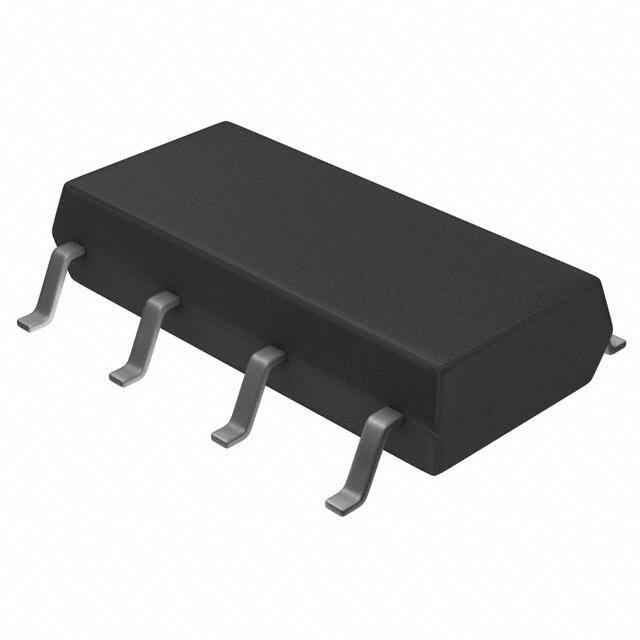
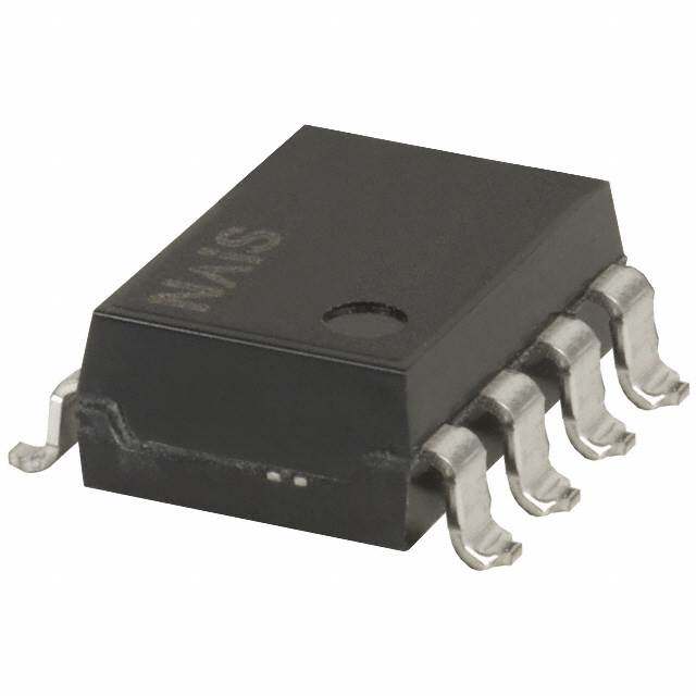
ICGOO电子元器件商城为您提供AQW612S由Panasonic Corporation设计生产,在icgoo商城现货销售,并且可以通过原厂、代理商等渠道进行代购。 AQW612S价格参考。Panasonic CorporationAQW612S封装/规格:固态继电器, 固体继电器 继电器 SPST-NO + SPST-NC(1 Form A 和 B) 8-SOP(0.173",4.40mm 宽)。您可以下载AQW612S参考资料、Datasheet数据手册功能说明书,资料中有AQW612S 详细功能的应用电路图电压和使用方法及教程。
Panasonic Electric Works(现为 Panasonic Industrial Devices)生产的 AQW612S 是一款固态继电器(SSR,Solid State Relay),广泛应用于需要高可靠性和低噪声开关的场景。以下是 AQW612S 的主要应用场景:

 1. 工业自动化控制
   - AQW612S 常用于工业设备中的电气控制,例如 PLC 输出控制、电机启动/停止、阀门控制等。
   - 它可以实现对加热器、冷却风扇或小型电机等负载的精确控制,适合需要频繁开关的场合。

 2. 温度控制系统
   - 在恒温控制设备中(如烤箱、烘干机、热压机等),AQW612S 能够通过 PID 控制器调节加热元件的通断,从而实现精准的温度管理。
   - 其零交叉开关功能可减少对电网的冲击并延长负载寿命。

 3. 照明控制
   - AQW612S 可用于控制 LED 灯、荧光灯或其他类型的灯具,尤其是在需要调光或定时开关的应用中。
   - 固态继电器的无触点设计避免了传统机械继电器在频繁开关时产生的电弧和磨损问题。

 4. 家用电器
   - 在家用电器(如微波炉、空调、洗衣机等)中,AQW612S 能够安全地控制压缩机、加热元件或风扇电机的运行。
   - 其紧凑的外形和高可靠性使其非常适合嵌入式应用。

 5. 医疗设备
   - 在某些医疗设备中(如诊断仪器、理疗设备等),AQW612S 提供稳定的电力切换能力,确保设备运行的安全性和准确性。

 6. 实验室与测试设备
   - AQW612S 可用于实验仪器中的电源切换或信号隔离,支持远程控制和自动化操作。
   - 其电磁干扰小的特点特别适合对环境要求较高的精密测试场景。

 7. 新能源领域
   - 在太阳能逆变器、储能系统或其他新能源相关设备中,AQW612S 可以用作辅助电路的开关元件,保证系统的高效运行。

 特性优势
- 高绝缘性能:提供良好的输入输出隔离,确保安全性。
- 长寿命:无机械部件,使用寿命远超传统继电器。
- 低噪音:无机械触点动作,适用于对电磁干扰敏感的场合。
- 快速响应:毫秒级开关速度,适合动态控制需求。

综上所述,AQW612S 的应用场景涵盖了工业、商业及家用等多个领域,尤其适合需要高频次、高精度和高稳定性的电力切换场合。
| 参数 | 数值 |
| 产品目录 | |
| 描述 | RELAY OPTO 60V 0.45A SOP8固态继电器-PCB安装 PhotoMOS (MOSFET) relay |
| 产品分类 | |
| 品牌 | Panasonic Electric Works |
| 产品手册 | |
| 产品图片 |
|
| rohs | RoHS 合规性豁免无铅 / 符合限制有害物质指令(RoHS)规范要求 |
| 产品系列 | 固态继电器,固态继电器-PCB安装,Panasonic Industrial Devices AQW612SPhotoMOS™ AQW |
| mouser_ship_limit | 该产品可能需要其他文件才能进口到中国。 |
| 数据手册 | |
| 产品型号 | AQW612S |
| 产品 | Telecommunication Relays |
| 产品目录绘图 |
|
| 产品目录页面 | |
| 产品种类 | 固态继电器-PCB安装 |
| 产品类型 | PCB Mount |
| 供应商器件封装 | 8-SOP |
| 其它名称 | 255-2678 |
| 其它有关文件 | |
| 包装 | 管件 |
| 商标 | Panasonic Industrial Devices |
| 安装类型 | 表面贴装 |
| 安装风格 | SMD/SMT |
| 导通电阻 | 2.5 欧姆 |
| 封装 | Tube |
| 封装/外壳 | 8-SOP (0.173", 4.40mm) |
| 封装/箱体 | SOP-8 |
| 工厂包装数量 | 50 |
| 应用说明 | |
| 控制电压范围 | 1.5 V to 5 V |
| 标准包装 | 50 |
| 特色产品 | http://www.digikey.com/cn/zh/ph/Panasonic/PhotoMOS.html |
| 电压-负载 | 0 ~ 60 V |
| 电压-输入 | 1.14VDC |
| 电路 | DPST-NO/NC(1 A 形和 B 形) |
| 端子类型 | 鸥翼型 |
| 端接类型 | Gull Wing Lead |
| 继电器类型 | |
| 触点形式 | SPST (1 Form A) |
| 负载电压额定值 | 60 V |
| 负载电流 | 450mA |
| 负载电流额定值 | 450 mA |
| 输入电流 | 50 mA |
| 输入转输出绝缘方法 | Optocoupler |
| 输出类型 | AC,DC |
| 输出设备 | MOSFET |


- 商务部:美国ITC正式对集成电路等产品启动337调查
- 曝三星4nm工艺存在良率问题 高通将骁龙8 Gen1或转产台积电
- 太阳诱电将投资9.5亿元在常州建新厂生产MLCC 预计2023年完工
- 英特尔发布欧洲新工厂建设计划 深化IDM 2.0 战略
- 台积电先进制程称霸业界 有大客户加持明年业绩稳了
- 达到5530亿美元!SIA预计今年全球半导体销售额将创下新高
- 英特尔拟将自动驾驶子公司Mobileye上市 估值或超500亿美元
- 三星加码芯片和SET,合并消费电子和移动部门,撤换高东真等 CEO
- 三星电子宣布重大人事变动 还合并消费电子和移动部门
- 海关总署:前11个月进口集成电路产品价值2.52万亿元 增长14.8%
.jpg)
PDF Datasheet 数据手册内容提取
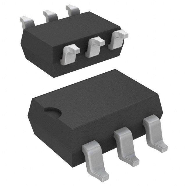
(AQW610S) (AQW612S) Both N.O. and N.C. contacts incorporated in a small GU SOP 1 Form A & 1 Form B SOP8-pin package (AQW61❍S) FEATURES TYPICAL APPLICATIONS 4.4 1. Normally open and normally closed • Power supply 9.37 .173 .369 2.1 contacts in a SOP package • Measuring equipment .083 The device comes in a miniature SOP • Security equipment mm inch measuring (W) 4.4 × (L) 9.37 × (H) 2.1 • Telephone equipment mm (W) .173× (L) .369× (H) .083 inch — • Computer input machines approx. 38% of the volume and 66% of • Industrial robots 1 8 N.C. the footprint size of DIP type. 2 7 2. 60V type couples high capacity 3 6 (0.45A) with low on-resistance (Typ. 1Ω) (AQW612S). 4 5 N.O. 3. Applicable for 1 Form A and 1 Form B use as well as two independent 1 Form A and 1 Form B RoHS compliant use 4. Controls low-level analog signals PhotoMOS feature extremely low closed- circuit offset voltage to enable control of low-level analog signals without distortion 5. Low-level off-state leakage current of max. 1 μA TYPES Output rating* Part No. Packing quantity Tape and reel packing style Load Load Package voltage current Tube packing style Picked from the Picked from the Tube Tape and reel 1/2/3/4-pin side 5/6/7/8-pin side 1 tube contains: 60V 450mA AQW612S AQW612SX AQW612SZ AC/DC 50 pcs. SOP8-pin 1,000 pcs. dual use 1 batch contains: 350V 100mA AQW610S AQW610SX AQW610SZ 1,000 pcs. * Indicate the peak AC and DC values. Note:The packing style indicator “X” or “Z” are not marked on the device. RATING 1. Absolute maximum ratings (Ambient temperature: 25°C 77°F) Item Symbol AQW612S AQW610S Remarks LED forward current IF 50 mA LED reverse voltage VR 5 V Input Peak forward current IFP 1 A f = 100 Hz, Duty factor = 0.1% Power dissipation Pin 75 mW Load voltage (peak AC) VL 60 V 350 V Peak AC, DC Output Continuous load current IL 0.45 A (0.55 A) 0.1 A (0.13 A) ( ): in case of using only 1a or 1b, 1 channel Peak load current Ipeak 1.5 A 0.3 A 100 ms (1 shot), VL = DC Power dissipation Pout 600 mW Total power dissipation PT 650 mW I/O isolation voltage Viso 1,500 Vrms Operating Topr –40 to +85°C –40 to +185°F (Non-icing at low temperatures) Ambient temperature Storage Tstg –40 to +100°C –40 to +212°F –1– ASCTB137E 201703-T
GU SOP 1 Form A & 1 Form B (AQW61❍S) 2. Electrical characteristics (Ambient temperature: 25°C 77°F) Item Symbol AQW612S AQW610S Condition LED operate current TMyapxicimalum IIFFoonff ((NN..OC..)) 03.9 m mAA IL = Max. Input LED reverse current MTyipniicmaulm IIFFoofnf ((NN..OC..)) 00..48 mmAA IL = Max. Typical 1.25 V (1.14 V at IF = 5 mA) LED dropout voltage VF IF = 50 mA Maximum 1.5 V Typical 1 Ω 18 Ω IF = 5 mA (N.O.) On resistance Maximum Ron 2.5 Ω 25 Ω IIFL == 0M maxA. (N.C.) Output Within 1 s IF = 0 mA (N.O.) Off state leakage current Maximum ILeak 1 μA IF= 5 mA (N.C.) VL = Max. Operate time* Typical Ton (N.O.) 0.65 ms (N.O.), 0.9 ms (N.C.) 0.28 ms (N.O.), 0.52 ms (N.C.) IF = 0 mA ➝ 5 mA Maximum Toff (N.C.) 3.0 ms 1.0 ms IL = Max. Transfer Reverse time* TMyapxicimalum TToofnf ((NN..OC..)) 0.08 ms (N.1O.0.) ,m 0s.2 ms (N.C.) 0.04 ms (N.O1..0), m0.s23 ms (N.C.) IIFL == M5 amxA. ➝ 0 mA characteristics Typical 0.8 pF f = 1 MHz I/O capacitance Maximum Ciso 1.5 pF VB = 0 V Initial I/O isolation resistance Minimum Riso 1,000 MΩ 500 V DC *Operate/Reverse time 1) N.O. 2) N.C. Input Input 90% Output 10% Output 10% Ton Toff 90% Toff Ton 3. Recommended operating conditions (Ambient temperature: 25°C 77°F) Please use under recommended operating conditions to obtain expected characteristics. Number of Item Symbol Min. Max. Unit used channels LED current IF 5 30 mA Load voltage (Peak AC) VL — 48 V AQW612S 1ch 0.55 Continuous load current IL 2ch — 0.45 A Load voltage (Peak AC) VL — 280 V AQW610S 1ch 0.13 Continuous load current IL 2ch — 0.1 A ■ These products are not designed for automotive use. If you are considering to use these products for automotive applications, please contact your local Panasonic Corporation technical representative. –2– ASCTB137E 201703-T
GU SOP 1 Form A & 1 Form B (AQW61❍S) REFERENCE DATA 1. Load current vs. ambient temperature 2. On resistance vs. ambient temperature 3. Operate time vs. ambient temperature characteristics characteristics characteristics Allowable ambient temperature:–40 to +85°C Measured portion: between terminals 5 and 6, LED current: 5 mA; –40 to +185°F 7 and 8; LED current: 5 mA; Load voltage: Max. (DC); Load voltage: Max. (DC); Continuous load current: Max. (DC) Continuous load current: Max. (DC) 600 50 2.0 AQW612S (Using only 1 channel) Between terminals 5 and 6(N.O.) Between terminals 5 and 6(N.O.) Between terminals 7 and 8(N.C.) Between terminals 7 and 8(N.C.) 500 AQW612S Load current, mA340000 (Using 2 channels) ΩOn resistance, 234000 AQW610S Operate time, ms011...826 AQW612S 200 AQW610S (Using only 1 channel) AQW610S 10 0.4 100 (Using 2 channels) AQW612S AQW610S 0 0 0 -40 -20 0 20 40 60 8085 100 -40 -20 0 20 40 60 8085 -40 -20 0 20 40 60 8085 Ambient temperature, °C Ambient temperature, °C Ambient temperature, °C 4. Reverse time vs. ambient temperature 5. LED operate current vs. ambient 6. LED reverse current vs. ambient characteristics temperature characteristics temperature characteristics LED current: 5 mA; Load voltage: Max. (DC); Load voltage: Max. (DC); Load voltage: Max. (DC); Continuous load current: Max. (DC) Continuous load current: Max. (DC) Continuous load current: Max. (DC) 1.0 5 5 Between terminals 5 and 6(N.O.) Between terminals 5 and 6(N.O.) Between terminals 5 and 6(N.O.) Between terminals 7 and 8(N.C.) Between terminals 7 and 8(N.C.) A Between terminals 7 and 8(N.C.) A m Reverse time, ms000...864 AQW612S AQW610S ED operate current, m 234 LED reverse current, 234 L 0.2 1 1 0 0 0 -40 -20 0 20 40 60 8085100 –40 –20 0 20 40 60 8085 –40 –20 0 20 40 60 8085 Ambient temperature, °C Ambient temperature, °C Ambient temperature, °C 7. LED dropout voltage vs. ambient 8-(1). Current vs. voltage characteristics of 8-(2). Current vs. voltage characteristics of temperature characteristics output at MOS portion output at MOS portion LED current: 5 to 50 mA Measured portion: between terminals 5 and 6, 7 and 8; Measured portion: between terminals 5 and 6, 7 and 8; Ambient temperature: 25°C 77°F Ambient temperature: 25°C 77°F 1.5 140 0.6 opout voltage, V11..43 B5B7 eeaattnnwwddee ee68nn (( NNttee..OCrrmm..))iinnaallCurrent, mAss 11246820000000 B5B7 eeaattnnwwddee ee68nn (( NNttee..OCrrmm..))iinnCurrent, Aaallss00..24 AQW612S LED dr11..21 532000mmmAAA -3 -2.5 -2-1.5-1 -0.5 --24000.5 1Vo1l.t5ag2e, V2.5 3 -1 -0.5 00-0.2 Vo0lt.a5ge, V 1 10mA -60 5mA -80 1.0 -100 -0.4 AQW610S -120 0 -140 -0.6 –40 –20 0 20 40 60 8085 Ambient temperature, °C 9-(1). Off state leakage current vs. load voltage 9-(2). Off state leakage current vs. load voltage 10. Operate time vs. LED forward current characteristics characteristics characteristics Measured portion: between terminals 5 and 6, 7 and 8; Measured portion: between terminals 5 and 6, 7 and 8; Measured portion: between terminals 5 and 6, 7 and 8; Ambient temperature: 25°C 77°F Ambient temperature: 25°C 77°F Load voltage: Max. (DC); Continuous load current: Max. (DC); Ambient temperature: 25°C 77°F 5 nt, A10–3 BBeettwweeeenn tteerrmmiinnaallss 57 aanndd 68((NN..OC..)) nt, A10–3 BBeettwweeeenn tteerrmmiinnaallss 57 aanndd 68((NN..OC..)) 4 BBeettwweeeenn tteerrmmiinnaallss 57 aanndd 68((NN..OC..)) Off state leakage curre1100––69 AQW610S Off state leakage curre1100––69 AQW612S Operate time, ms 23 AQAWQ6W106S12S 1 10–12 10–12 0 0 20 40 60 80 100 0 20 40 60 80 100 0 10 20 30 40 50 60 Load voltage, V Load voltage, V LED forward current, mA –3– ASCTB137E 201703-T
GU SOP 1 Form A & 1 Form B (AQW61❍S) 11. Reverse time vs. LED forward current 12. Output capacitance vs. applied voltage characteristics characteristics Measured portion: between terminals 5 and 6, 7 and 8; Measured portion: between terminals 5 and 6, 7 and 8; Load voltage: Max. (DC); Continuous load current: LED current: 0 mA (N.O.), 5 mA (N.C.); Frequency: Max. (DC); Ambient temperature: 25°C 77°F 1 MHz; Ambient temperature: 25°C 77°F 0.5 500 Between terminals 5 and 6(N.O.) Between terminals 5 and 6(N.O.) Between terminals 7 and 8(N.C.) Between terminals 7 and 8(N.C.) F ms0.4 e, p400 Reverse time, 00..32 AQW610S utput capacitanc320000 AQW612S O AQW612S 0.1 100 AQW610S 0 0 0 1100 2200 3300 4400 5500 6600 0 10 20 30 40 50 60 LED forward current, mA Applied voltage, V –4– ASCTB137E 201703-T
None
Mouser Electronics Authorized Distributor Click to View Pricing, Inventory, Delivery & Lifecycle Information: P anasonic: AQW610SZ AQW612S AQW612SX AQW612SZ AQW610S