ICGOO在线商城 > 集成电路(IC) > PMIC - 稳压器 - 线性 > AP130-28YL-13
 Datasheet下载
- 型号: AP130-28YL-13
- 制造商: Diodes Inc.
- 库位|库存: xxxx|xxxx
- 要求:
| 数量阶梯 | 香港交货 | 国内含税 |
| +xxxx | $xxxx | ¥xxxx |
查看当月历史价格
查看今年历史价格
AP130-28YL-13产品简介:
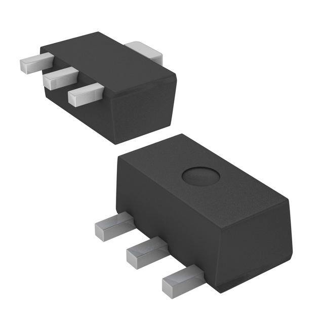
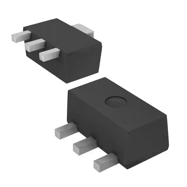
ICGOO电子元器件商城为您提供AP130-28YL-13由Diodes Inc.设计生产,在icgoo商城现货销售,并且可以通过原厂、代理商等渠道进行代购。 AP130-28YL-13价格参考。Diodes Inc.AP130-28YL-13封装/规格:PMIC - 稳压器 - 线性, Linear Voltage Regulator IC Positive Fixed 1 Output 2.8V 300mA SOT-89-3。您可以下载AP130-28YL-13参考资料、Datasheet数据手册功能说明书,资料中有AP130-28YL-13 详细功能的应用电路图电压和使用方法及教程。
Diodes 公司的 AP130-28YL-13 是一款线性稳压器(LDO),属于电源管理集成电路(PMIC)中的低压差稳压器类别。该器件常用于需要稳定电压输出、低噪声和高电源抑制比(PSRR)的应用场景。

AP130-28YL-13 的典型输出电压为2.8V,适用于便携式电子设备、电池供电系统以及对电压稳定性要求较高的数字和射频电路。例如,该器件可应用于智能手机、平板电脑、可穿戴设备、无线通信模块(如Wi-Fi、蓝牙模块)和传感器模块等产品中,为处理器、射频收发器、摄像头模块或其他敏感模拟电路提供干净稳定的电源。

此外,由于其低压差特性,AP130-28YL-13 能在输入和输出电压差较小的情况下仍保持稳定输出,提高了电池使用效率,延长了设备续航时间。其封装形式为SOT25,体积小巧,适合高密度PCB布局。

综上,AP130-28YL-13 主要用于对电源噪声敏感、空间受限且需要高效能稳压的便携式和无线电子产品中。
| 参数 | 数值 |
| 产品目录 | 集成电路 (IC)集成电路 (IC) |
| 描述 | IC REG LDO 2.8V 0.3A SOT89-3IC REG LDO 2.8V 0.3A SOT89-3 |
| 产品分类 | |
| 品牌 | Diodes IncorporatedDiodes/Zetex |
| 数据手册 | |
| 产品图片 |
|
| 产品型号 | AP130-28YL-13AP130-28YL-13 |
| rohs | 无铅 / 符合限制有害物质指令(RoHS)规范要求无铅 / 符合限制有害物质指令(RoHS)规范要求 |
| RoHS指令信息 | http://diodes.com/download/4349http://diodes.com/download/4349 |
| 产品系列 | -- |
| 供应商器件封装 | SOT-89-3SOT-89-3 |
| 其它名称 | AP130-28YLDICT |
| 包装 | 剪切带 (CT)带卷 (TR) |
| 安装类型 | 表面贴装表面贴装 |
| 封装/外壳 | TO-243AATO-243AA |
| 工作温度 | -40°C ~ 85°C-40°C ~ 85°C |
| 标准包装 | 12,500 |
| 电压-跌落(典型值) | 0.4V @ 300mA0.4V @ 300mA |
| 电压-输入 | 最高 5.5V最高 5.5V |
| 电压-输出 | 2.8V2.8V |
| 电流-输出 | 300mA300mA |
| 电流-限制(最小值) | 350mA350mA |
| 稳压器拓扑 | 正,固定式正,固定式 |
| 稳压器数 | 11 |


PDF Datasheet 数据手册内容提取
AP130 300mA LOW DROPOUT (LDO) LINEAR REGULATOR Features Description • Input Voltage Range: 2.7V to 5.5V The AP130 is a 300mA, fixed output voltage, low dropout • Dropout Voltage 400mV at 300mA Output Current linear regulator. The device includes pass element, error • Guaranteed 300mA Output Current amplifier, band-gap, current-limit and thermal shutdown • Internal RON = 1.5Ω PMOS Draws No Base Current circuitry. The characteristics of low dropout voltage and less quiescent current make it good for some critical • Low Quiescent Current 50µA current application, for example, some battery powered • Output Voltage: 1.5V/1.8V/2.0V/2.5V/2.8V/3.0V/ devices. The typical quiescent current is approximately • 3.3V/3.5; Accuracy 2% 50µA from zero to maximum load. Due to internal flexible • Fast Transient Response design, results in extensively fixed output voltage versions • Good Load Regulation and make it convenient to use for applications. Built-in • Current Limit and Thermal Shutdown Protection current-limit and thermal-shutdown functions prevent any • Short Circuit Current Fold-Back fault condition from IC damage. • Lead Free Packages: SC59, SC59R, SOT89-3L, and SOT89R-3L • SC59, SC59R, SOT23, SOT89-3L, and SOT89R-3L: Available in “Green” Molding Compound (No Br, Sb) (Note 9) • Lead Free Finish/ RoHS Compliant (Note 1) Notes: 1. EU Directive 2002/95/EC (RoHS). All applicable RoHS exemptions applied. Please visit our website at http://www.diodes.com/products/lead_free.html. Applications • Battery Powered Device • CD-ROM, DVD, and LAN Card • PC Peripheral • Wireless Communication Typical Application Circuit AP130 IN OUT GND V V IN OUT C C IN OUT 1uF 10uF AP130 1 of 11 December 2011 Document number: DS31027 Rev. 8 - 2 www.diodes.com © Diodes Incorporated
AP130 300mA LOW DROPOUT (LDO) LINEAR REGULATOR Pin Assignments Package No. Pin Name Description Type Code (Top View) 1 IN 3 W 2 OUT 1 2 3 GND (SC59) (Top View) 1 GND 3 R 2 OUT 1 2 (SC59R) 3 IN (Top View) 1 IN IN: Power Input 3 SA 2 OUT OUT: Output Voltage 1 2 GND: Ground 3 GND (SOT23) (Top View) 1 OUT Y 2 GND 1 2 3 (SOT89-3L) 3 IN (Top View) 1 GND YR 2 IN 1 2 3 (SOT89R-3L) 3 OUT AP130 2 of 11 December 2011 Document number: DS31027 Rev. 8 - 2 www.diodes.com © Diodes Incorporated
AP130 300mA LOW DROPOUT (LDO) LINEAR REGULATOR Functional Block Diagram IN OUT Error Current Limit Amp - + Thermal Bandgap 1.08V Shutdown GND Absolute Maximum Ratings Symbol Parameter Rating Unit VCC Input Voltage +6 V TOP Operating Junction Temperature -40 to +125 ºC TST Storage Temperature Range -65 to +150 ºC Recommended Operating Conditions Symbol Parameter Min Max Unit VIN Input Voltage 2.7 5.5 V IOUT Output Current 0 300 mA TA Operating Ambient Temperature -40 85 °C AP130 3 of 11 December 2011 Document number: DS31027 Rev. 8 - 2 www.diodes.com © Diodes Incorporated
AP130 300mA LOW DROPOUT (LDO) LINEAR REGULATOR Electrical Characteristics T = 25ºC, C = 1µF, C = 10µF, unless otherwise specified. A IN OUT Symbol Parameter Conditions Min Typ. Max Unit VDROP Dropout Voltage (Note 2) IL = 300mA - 400 500 mV ILIMIT Current Limit (Note 3) VIN = 5V, VOUT = 0V 350 450 - mA Ishort Short Circuit Current VOUT < 1.05V - 150 300 mA IOUT = 1mA, ΔVLINE Line Regulation - 0.1 0.3 %/V V = (V +1V) to 5.5V IN OUT F = 100Hz, PSRR Ripple Rejection CIN = 1μF, CO = 10uF, - 58 - dB I = 100mA L ΔVLOAD Load Regulation (Note 4) IL = 1~300mA, VIN = 5V - 30 40 mV Output Voltage Accuracy IL = 1mA, VIN = 5V -2 - +2 % ΔVOUT Output Voltage Temperature Coefficient - 50 150 PPM/ºC (Note 5) IQ Quiescent Current IL = 0mA, VIN = 5V - 50 100 μA SC59/SC59R (Note 6) - 250 - SOT23 (Note 7) - 200 - θJA Thermal Resistance Junction-to-Ambient ºC/W SOT89-3L/SOT89R-3L - - 100 (Note 8) SC59/SC59R (Note 6) - 79 - SOT23 (Note 7) - 43 - θJC Thermal Resistance Junction-to-Case ºC/W SOT89-3L/SOT89R-3L - - 23 (Note 8) Notes: 2. Dropout voltage is defined as the input to output differential voltage. Dropout is measured at constant junction temperature by using pulsed on time, and the criterion is VOUT inside target value ±2%. This test is skipped at the condition of VIN<3V. 3. Current limit is measured at constant junction temperature by using pulsed testing with a low ON time. 4. Regulation is measured at constant junction temperature by using pulsed testing with a low ON time. 5. Guaranteed by design. 6. Test condition for SC59/SC59R: Devices mounted on FR-4 PC board, 1*MRP, 2oz copper, single sided, calibrate at TJ=125ºC, TA=25ºC, with minimum recommended pad layout. 7. Test condition for SOT23: Devices mounted on FR-4 PC board, 1*MRP, calibrate at TJ=85ºC, TA=29ºC. 8. Test condition for SOT89-3L/SOT89R-3L: No Heat Sink, no air flow. AP130 4 of 11 December 2011 Document number: DS31027 Rev. 8 - 2 www.diodes.com © Diodes Incorporated
AP130 300mA LOW DROPOUT (LDO) LINEAR REGULATOR Typical Performance Characteristics AP130 PSRR vs. Frequency AP130 V vs. Load Current 70 3.35 out 65 3.345 60 55 3.34 50 B) 45 3.335 RR (d 3450 (V)ut 3.33 S 30 Vo P 3.325 25 20 3.32 15 10 3.315 5 0 3.31 10 100 1K 10K 100K 1M 0 30 60 90 120 150 180 210 240 270 300 Load Current Frequency (Hz) ( A) AP130 GND Current vs. Input Voltage AP130 Dropout vs. Load 50 450 45 400 VOUT=3.3V 40 350 A) 35 u 300 D Current ( 12235050 Dropout (V) 122505000 N G 10 100 5 50 0 0 0 0.5 1 1.5 2 2.5 3 3.5 4 4.5 5 5.5 6 0 50 100 150 200 250 300 Input Voltage (V) Load (Io) (mA) Functional Descriptions A minimum of 10µF capacitor must be connected from OUT to ground to insure stability. Typically a large storage capacitor is connected from V to ground to ensure that the input voltage does not sag below the minimum dropout voltage during the IN load transient response. AP130 5 of 11 December 2011 Document number: DS31027 Rev. 8 - 2 www.diodes.com © Diodes Incorporated
AP130 300mA LOW DROPOUT (LDO) LINEAR REGULATOR Ordering Information AP 130 - XX XX X - X Output Voltage Package Lead Free Packing 15 : 1.5V W : SC59 L : Lead Free 7/13 : Tape & Reel 18 : 1.8V R : SC59R G : Green (Note 9) 20 : 2.0V SA : SOT23 25 : 2.5V Y : SOT89-3L 28 : 2.8V YR : SOT89R-3L 30 : 3.0V 33 : 3.3V 35 : 3.5V Packaging 7”/13” Tape and Reel Device Package Code (Note 10) Quantity Part Number Suffix AP130-XXWL-7 W SC59 3000/Tape & Reel -7 Lead-free AP130-XXWG-7 W SC59 3000/Tape & Reel -7 AP130-XXRL-7 R SC59R 3000/Tape & Reel -7 Lead-free AP130-XXRG-7 R SC59R 3000/Tape & Reel -7 AP130-XXSAG-7 SA SOT23 3000/Tape & Reel -7 AP130-XXYL-13 Y SOT89-3L 2500/Tape & Reel -13 Lead-free AP130-XXYG-13 Y SOT89-3L 2500/Tape & Reel -13 AP130-XXYRL-13 YR SOT89R-3L 2500/Tape & Reel -13 Lead-free AP130-XXYRG-13 YR SOT89R-3L 2500/Tape & Reel -13 Notes: 9. SOT23 is available in “Green” product only. 10. Pad layout as shown on Diodes Inc. suggested pad layout document AP02001, which can be found on our website at http://www.diodes.com/datasheets/ap02001.pdf. AP130 6 of 11 December 2011 Document number: DS31027 Rev. 8 - 2 www.diodes.com © Diodes Incorporated
AP130 300mA LOW DROPOUT (LDO) LINEAR REGULATOR Marking Information (1) SC59, SC59R and SOT23 ( Top View ) 3 XX : Identification code Y : Year 0~9 W : Week : A~Z : 1~26 week; XX Y W X a~z : 27~52 week; z represents 52 and 53 week 1 2 X : A~Z : Green a~z : Lead Free Device Package (Note 11) Identification Code AP130-15W SC59W CA AP130-18W SC59W CD AP130-20W SC59W CF AP130-25W SC59W CK AP130-28W SC59W CN AP130-30W SC59W CP AP130-33W SC59W CS AP130-35W SC59W CU AP130-15R SC59R GO AP130-18R SC59R GR AP130-20R SC59R GT AP130-25R SC59R GY AP130-28R SC59R H1 AP130-30R SC59R H3 AP130-33R SC59R H9 AP130-35R SC59R HB AP130-15SA SOT23 U2 AP130-18SA SOT23 U3 AP130-20SA SOT23 U4 AP130-25SA SOT23 U5 AP130-28SA SOT23 U6 AP130-30SA SOT23 U7 AP130-33SA SOT23 U8 AP130-35SA SOT23 U9 AP130 7 of 11 December 2011 Document number: DS31027 Rev. 8 - 2 www.diodes.com © Diodes Incorporated
AP130 300mA LOW DROPOUT (LDO) LINEAR REGULATOR Marking Information (cont.) (2) SOT89-3L and SOT89R-3L ( Top View ) XX : Identification code Y : Year : 0~9 X X W : Week : A~Z : 1~26 week; Y W X a~z : 27~52 week; z represents 52 and 53 week X : Internal code 1 2 3 A~Z : Green a~z : Lead Free Device Package (Note 11) Identification Code AP130-15Y SOT89-3L CA AP130-18Y SOT89-3L CD AP130-20Y SOT89-3L CF AP130-25Y SOT89-3L CK AP130-28Y SOT89-3L CN AP130-30Y SOT89-3L CP AP130-33Y SOT89-3L CS AP130-35Y SOT89-3L CU AP130-15YR SOT89R-3L GO AP130-18YR SOT89R-3L GR AP130-20YR SOT89R-3L GT AP130-25YR SOT89R-3L GY AP130-28YR SOT89R-3L H1 AP130-30YR SOT89R-3L H3 AP130-33YR SOT89R-3L H9 AP130-35YR SOT89R-3L HB Notes: 11. For Packaging Details, go to our website at http://www.diodes.com/datasheets/ap02007.pdf. AP130 8 of 11 December 2011 Document number: DS31027 Rev. 8 - 2 www.diodes.com © Diodes Incorporated
AP130 300mA LOW DROPOUT (LDO) LINEAR REGULATOR Package Outline Dimensions (All Dimensions in mm) (1) Package Type: SC59 and SC59R 0.35/0.50 0/0 TOP VIEW 57 2.70/ 1.1. 3.00 1.90 2.90/3.10 1.00/ 1.30 0.10/0.20 0.013/0.10 0.95 0.35/0.55 0O/8O (2) Package Type: SOT23 AP130 9 of 11 December 2011 Document number: DS31027 Rev. 8 - 2 www.diodes.com © Diodes Incorporated
AP130 300mA LOW DROPOUT (LDO) LINEAR REGULATOR Package Outline Dimensions (cont.) (3) Package Type: SOT89-3L and SOT89R-3L 1.40/1.75 Typ 1.60 1.7 8 4 2. yp 2.7 T 5 60 4.2 2. 4/ 35/ 3.9 2. 0.4 9 80/20 1. 1.3 0.1. 1.45/1.55 Typ 1.50 0.9 1.5 2.90/3.10 Land Pattern Recommendation (Unit: mm) Typ 3.00 50(2x) 80(2x) 4.40/4.60 Typ 4.50 00 65 1.1. 0/p 4y 1.T 0.36/0.480.41/0.53 0.36/0.48 0.35/0.43 Typ 0.42 Typ 0.47 Typ 0.42 Typ 0.39 AP130 10 of 11 December 2011 Document number: DS31027 Rev. 8 - 2 www.diodes.com © Diodes Incorporated
AP130 300mA LOW DROPOUT (LDO) LINEAR REGULATOR IMPORTANT NOTICE DIODES INCORPORATED MAKES NO WARRANTY OF ANY KIND, EXPRESS OR IMPLIED, WITH REGARDS TO THIS DOCUMENT, INCLUDING, BUT NOT LIMITED TO, THE IMPLIED WARRANTIES OF MERCHANTABILITY AND FITNESS FOR A PARTICULAR PURPOSE (AND THEIR EQUIVALENTS UNDER THE LAWS OF ANY JURISDICTION). Diodes Incorporated and its subsidiaries reserve the right to make modifications, enhancements, improvements, corrections or other changes without further notice to this document and any product described herein. Diodes Incorporated does not assume any liability arising out of the application or use of this document or any product described herein; neither does Diodes Incorporated convey any license under its patent or trademark rights, nor the rights of others. Any Customer or user of this document or products described herein in such applications shall assume all risks of such use and will agree to hold Diodes Incorporated and all the companies whose products are represented on Diodes Incorporated website, harmless against all damages. Diodes Incorporated does not warrant or accept any liability whatsoever in respect of any products purchased through unauthorized sales channel. Should Customers purchase or use Diodes Incorporated products for any unintended or unauthorized application, Customers shall indemnify and hold Diodes Incorporated and its representatives harmless against all claims, damages, expenses, and attorney fees arising out of, directly or indirectly, any claim of personal injury or death associated with such unintended or unauthorized application. Products described herein may be covered by one or more United States, international or foreign patents pending. Product names and markings noted herein may also be covered by one or more United States, international or foreign trademarks. LIFE SUPPORT Diodes Incorporated products are specifically not authorized for use as critical components in life support devices or systems without the express written approval of the Chief Executive Officer of Diodes Incorporated. As used herein: A. Life support devices or systems are devices or systems which: 1. are intended to implant into the body, or 2. support or sustain life and whose failure to perform when properly used in accordance with instructions for use provided in the labeling can be reasonably expected to result in significant injury to the user. B. A critical component is any component in a life support device or system whose failure to perform can be reasonably expected to cause the failure of the life support device or to affect its safety or effectiveness. Customers represent that they have all necessary expertise in the safety and regulatory ramifications of their life support devices or systems, and acknowledge and agree that they are solely responsible for all legal, regulatory and safety-related requirements concerning their products and any use of Diodes Incorporated products in such safety-critical, life support devices or systems, notwithstanding any devices- or systems-related information or support that may be provided by Diodes Incorporated. Further, Customers must fully indemnify Diodes Incorporated and its representatives against any damages arising out of the use of Diodes Incorporated products in such safety-critical, life support devices or systems. Copyright © 2011, Diodes Incorporated www.diodes.com AP130 11 of 11 December 2011 Document number: DS31027 Rev. 8 - 2 www.diodes.com © Diodes Incorporated