ICGOO在线商城 > 射频/IF 和 RFID > RF 天线 > ANT-2.4-JJB-RA
 Datasheet下载
- 型号: ANT-2.4-JJB-RA
- 制造商: LINX TECHNOLOGIES
- 库位|库存: xxxx|xxxx
- 要求:
| 数量阶梯 | 香港交货 | 国内含税 |
| +xxxx | $xxxx | ¥xxxx |
查看当月历史价格
查看今年历史价格
ANT-2.4-JJB-RA产品简介:
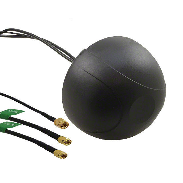
ICGOO电子元器件商城为您提供ANT-2.4-JJB-RA由LINX TECHNOLOGIES设计生产,在icgoo商城现货销售,并且可以通过原厂、代理商等渠道进行代购。 ANT-2.4-JJB-RA价格参考。LINX TECHNOLOGIESANT-2.4-JJB-RA封装/规格:RF 天线, 2.4GHz 蓝牙, Thread, Wi-Fi, Zigbee™ 圆顶 RF 天线 2.39GHz ~ 2.48GHz 3.3dBi 焊接 通孔。您可以下载ANT-2.4-JJB-RA参考资料、Datasheet数据手册功能说明书,资料中有ANT-2.4-JJB-RA 详细功能的应用电路图电压和使用方法及教程。
Linx Technologies Inc. 是一家专注于射频(RF)解决方案的制造商,其型号为 ANT-2.4-JJB-RA 的产品是一款工作在 2.4 GHz 频段的 RF 天线。

该天线主要适用于无线通信应用,常见于以下几种应用场景:

1. 无线传感器网络:适用于 Zigbee、Bluetooth、Wi-Fi(2.4 GHz ISM 频段)等短距离无线通信协议,广泛用于工业监测、智能家居、环境监控等领域。

2. 物联网(IoT)设备:作为连接核心组件,用于智能电表、远程控制设备、自动化系统等 IoT 终端,确保设备稳定接入无线网络。

3. 遥控与遥测设备:用于无人机、遥控玩具、安防设备等,实现远程控制和数据回传。

4. 医疗电子设备:如远程健康监测设备、便携式诊断仪器等,用于实现设备间无线数据传输。

5. 消费类电子产品:如无线耳机、智能穿戴设备、蓝牙音箱等,支持 2.4 GHz 频段的无线连接功能。

该天线采用表面贴装(SMT)设计,便于集成于小型 PCB 板中,适合空间受限的应用场景,具有良好的方向性和信号接收性能。
| 参数 | 数值 |
| 产品目录 | |
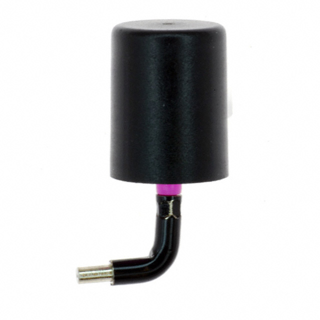
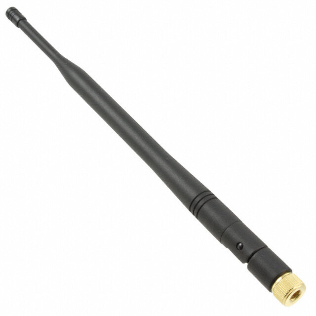
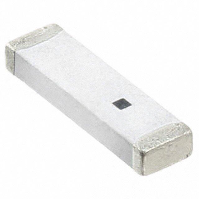
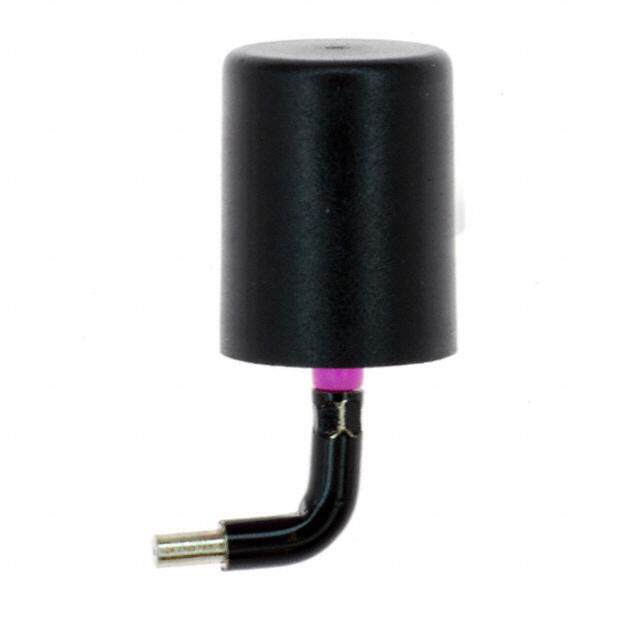
| 描述 | ANTENNA 2.45GHZ 7MM RT ANGLE天线 Perm Mnt Mini Ant. R Angle Post 2.45GHz |
| 产品分类 | |
| 品牌 | Linx Technologies |
| 产品手册 | |
| 产品图片 |
|
| rohs | 符合RoHS无铅 / 符合限制有害物质指令(RoHS)规范要求 |
| 产品系列 | Linx Technologies ANT-2.4-JJB-RAJJB - Antenna Factor |
| 数据手册 | |
| 产品型号 | ANT-2.4-JJB-RA |
| VSWR | 2 |
| 产品目录绘图 |
|
| 产品种类 | 天线 |
| 其它名称 | ANT24JJBRA |
| 包装 | 散装 |
| 商标 | Linx Technologies |
| 增益 | - |
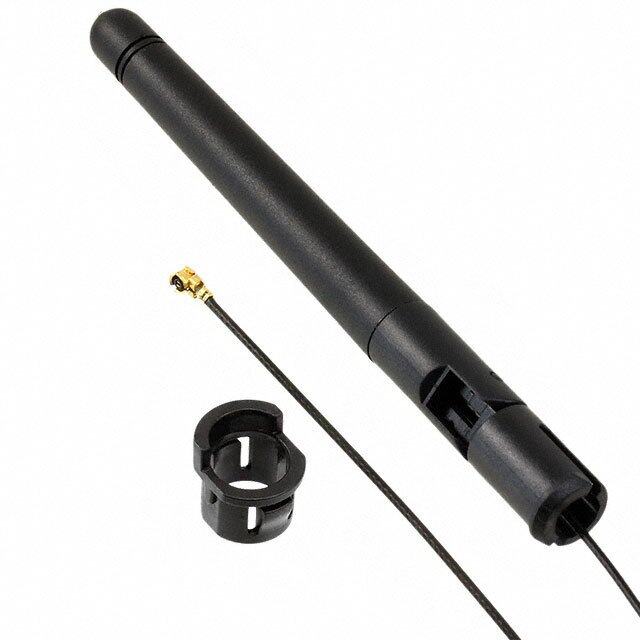
| 天线类型 | 鞭状:1/4 波,直角,固定式 |
| 安装类型 | 底座安装 |
| 封装 | Bulk |
| 尺寸 | 0.57 in H |
| 工厂包装数量 | 200 |
| 带宽 | 50 MHz |
| 技术类型 | 1/4 Wave Antenna |
| 标准包装 | 200 |
| 端接 | |
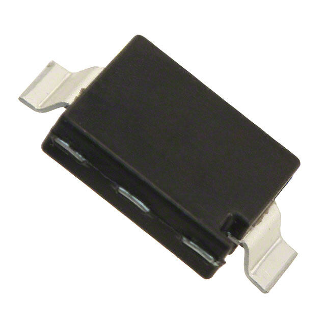
| 端接类型 | Through Hole |
| 系列 | JJB |
| 阻抗 | 50 Ohms |
| 频带数 | 1 |
| 频率 | 2.45 GHz |
| 高度 | 0.57 in |
| 高度(最大值) | 0.354"(9.00mm) |


- 商务部:美国ITC正式对集成电路等产品启动337调查
- 曝三星4nm工艺存在良率问题 高通将骁龙8 Gen1或转产台积电
- 太阳诱电将投资9.5亿元在常州建新厂生产MLCC 预计2023年完工
- 英特尔发布欧洲新工厂建设计划 深化IDM 2.0 战略
- 台积电先进制程称霸业界 有大客户加持明年业绩稳了
- 达到5530亿美元!SIA预计今年全球半导体销售额将创下新高
- 英特尔拟将自动驾驶子公司Mobileye上市 估值或超500亿美元
- 三星加码芯片和SET,合并消费电子和移动部门,撤换高东真等 CEO
- 三星电子宣布重大人事变动 还合并消费电子和移动部门
- 海关总署:前11个月进口集成电路产品价值2.52万亿元 增长14.8%
PDF Datasheet 数据手册内容提取
ANT-2.4-JJB-xx Data Sheet by Product Description 7.0 mm The JJB Series packs near the performance of a (0.28") conventional monopole into an incredibly compact quarter-inch (7mm) diameter package. These antennas are ideal for any OEM application 9.0 mm requiring a compact, cosmetically attractive, (0.35") low-cost antenna solution. The antenna features a through-hole feedline that can attach directly 17.6 mm (0.69") to a user’s PCB. Internal or external mounting is possible. 8.6 mm (0.34") Features 2.0 mm (0.08") • Very low cost • Ultra-compact package 1.0 mm (0.04") • Easily concealed internally • Good for internal or external mounting • Excellent performance • Omni-directional pattern • Use with plastic* enclosures 14.5 mm *Requires proximity ground plane ANT-916-J(0J.B57-"A)RNAT-916-JJB-RA No ground plaNneo ogrr otruancde splane or traces Electrical Specifications 5.5 mm (0.22u")nder the anteunnndaer the antenna Center Frequency: 2.45GHz 1.0 mm (0.04") Recom. Freq. Range: 2390–2480MHz Socket or plateSdo chkoelet or plated hole 5.5 mm Wavelength: ¼-wave Ground pl(0a.2n2e") Gonro buontdto pmlane on bottom VSWR: ≤ 2.0 typical at center layer for countlearypeori sfoer counterpoise Peak Gain: RA: 3.3dBi 50-ohm micros5t0ri-po hlinme microstrip line ST: –1.5dBi Recommended Mounting Impedance: 50-ohms Right Angle Straight Connection: Direct solder No ground plane Oper. Temp. Range: –40°C to +90°C or traces under the antenna RA electrical specifications and plots measured on a 3.81 cm x 8.38 cm (1.50" x 3.30") ground plane 1.91 mm (0.075") ST electrical specifications and plots measured on a 8.89 cm x plated hole 8.89 cm (3.50" x 3.50") ground plane Ground plane on Ordering Information bottom layer for counterpoise ANT-2.4-JJB-RA (Right-Angle) ANT-2.4-JJB-ST (Straight) 50-ohm microstrip line – 1 – Revised 4/11/16
Counterpoise Quarter-wave or monopole antennas require an associated ground plane counterpoise for proper operation. The size and location of the ground plane relative to the antenna will affect the overall performance of the antenna in the final design. When used in conjunction with a ground plane smaller than that used to tune the antenna, the center frequency typically will shift higher in frequency and the bandwidth will decrease. The proximity of other circuit elements and packaging near the antenna will also affect the final performance. For further discussion and guidance on the importance of the ground plane counterpoise, please refer to Linx Application Note AN-00501: Understanding Antenna Specifications and Operation. VSWR Graph VSWR 1.403 1.307 Reflected Power 3:1 25% 2:1 11% 1:1 0% CENTER 2.450GHz ST SPAN 200.000MHz CENTER 2.450GHz RA What is VSWR? The Voltage Standing Wave Ratio (VSWR) is a measurement of how well an antenna is matched to a source impedance, typically 50-ohms. It is calculated by measuring the voltage wave that is headed toward the load versus the voltage wave that is reflected back from the load. A perfect match will have a VSWR of 1:1. The higher the first number, the worse the match, and the more inefficient the system. Since a perfect match cannot ever be obtained, some benchmark for performance needs to be set. In the case of antenna VSWR, this is usually 2:1. At this point, 88.9% of the energy sent to the antenna by the transmitter is radiated into free space and 11.1% is either reflected back into the source or lost as heat on the structure of the antenna. In the other direction, 88.9% of the energy recovered by the antenna is transferred into the receiver. As a side note, since the “:1” is always implied, many data sheets will remove it and just display the first number. How to Read a VSWR Graph VSWR is usually displayed graphically versus frequency. The lowest point on the graph is the antenna’s operational center frequency. In most cases, this will be different than the designed center frequency due to fabrication tolerances. The VSWR at that point denotes how close to 50-ohms the antenna gets. Linx specifies the recommended bandwidth as the range where the typical antenna VSWR is less than 2:1. – 2 – Data Sheet ANT-2.4-JJB-xx by
Mouser Electronics Authorized Distributor Click to View Pricing, Inventory, Delivery & Lifecycle Information: L inx Technologies: ANT-2.4-JJB-RA ANT-2.4-JJB-ST