ICGOO在线商城 > 传感器,变送器 > 运动传感器 - 光学 > AMN14112
 Datasheet下载
- 型号: AMN14112
- 制造商: Panasonic Corporation
- 库位|库存: xxxx|xxxx
- 要求:
| 数量阶梯 | 香港交货 | 国内含税 |
| +xxxx | $xxxx | ¥xxxx |
查看当月历史价格
查看今年历史价格
AMN14112产品简介:
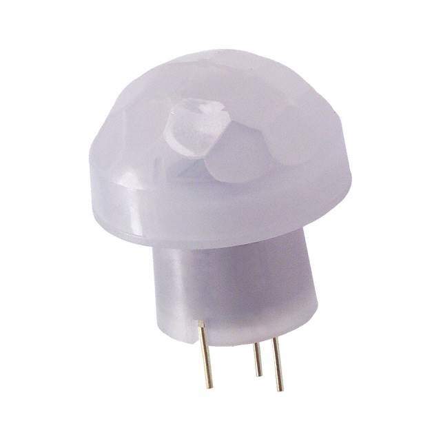
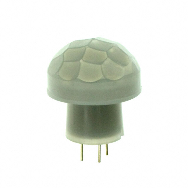
ICGOO电子元器件商城为您提供AMN14112由Panasonic Corporation设计生产,在icgoo商城现货销售,并且可以通过原厂、代理商等渠道进行代购。 AMN14112价格参考¥146.70-¥146.70。Panasonic CorporationAMN14112封装/规格:运动传感器 - 光学, Sensor Motion, Pyroelectric, PIR (Passive Infrared) 394" (10m) 32.8' Polyethylene, White Lens Cylinder。您可以下载AMN14112参考资料、Datasheet数据手册功能说明书,资料中有AMN14112 详细功能的应用电路图电压和使用方法及教程。
Panasonic Electric Works的AMN14112是一款光学运动传感器,主要应用于需要自动检测人体活动的场景。该传感器通过检测红外线变化来识别移动,常用于自动门、照明控制、安防系统、智能家电及节能设备中,提升便利性与能源效率。
| 参数 | 数值 |
| 产品目录 | |
| 描述 | SENSOR MOTION DIG 10M 5V WHT PCB板机接口移动感应器和位置传感器 DIGITAL 5VDC WHITE 10 METER DETECTION |
| 产品分类 | 运动传感器,检测器 (PIR)运动与定位传感器 |
| 品牌 | Panasonic Electric Works |
| 产品手册 | http://www.symbrion.eu/tiki-download_file.php?fileId=93 |
| 产品图片 |
|
| rohs | RoHS 合规性豁免无铅 / 符合限制有害物质指令(RoHS)规范要求 |
| 产品系列 | 板机接口移动感应器和位置传感器,Panasonic Industrial Devices AMN14112NaPiOn™ |
| 数据手册 | |
| 产品型号 | AMN14112 |
| 产品培训模块 | http://www.digikey.cn/PTM/IndividualPTM.page?site=cn&lang=zhs&ptm=7890 |
| 产品目录绘图 |
|
| 产品目录页面 | |
| 产品种类 | 板机接口移动感应器和位置传感器 |
| 传感器类型 | 运动,热电,PIR(无源红外) |
| 其它名称 | 255-1803 |
| 其它有关文件 | |
| 商标 | Panasonic Industrial Devices |
| 安装风格 | Through Hole |
| 封装 | Bulk |
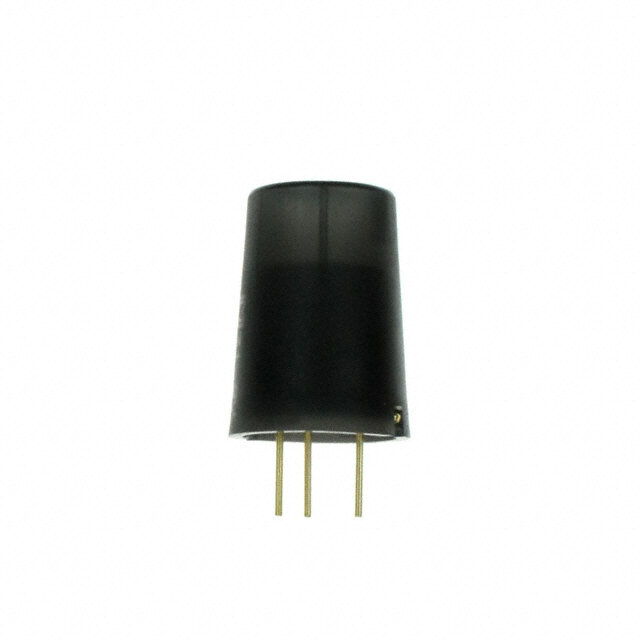
| 封装/外壳 | 圆柱型 |
| 工厂包装数量 | 50 |
| 感应距离 | 394"(10m) 32.8' |
| 最大工作温度 | + 60 C |
| 最小工作温度 | - 20 C |
| 标准包装 | 50 |
| 检测模式 | 10m |
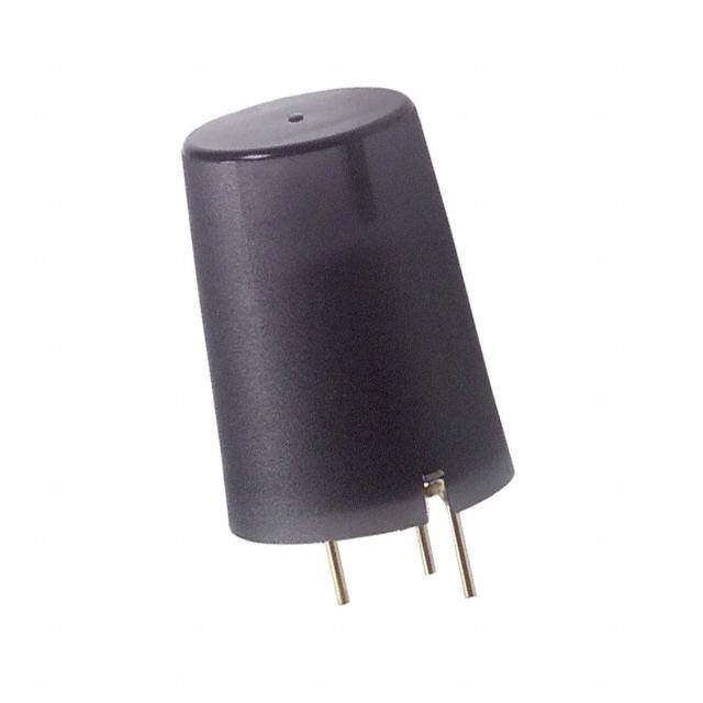
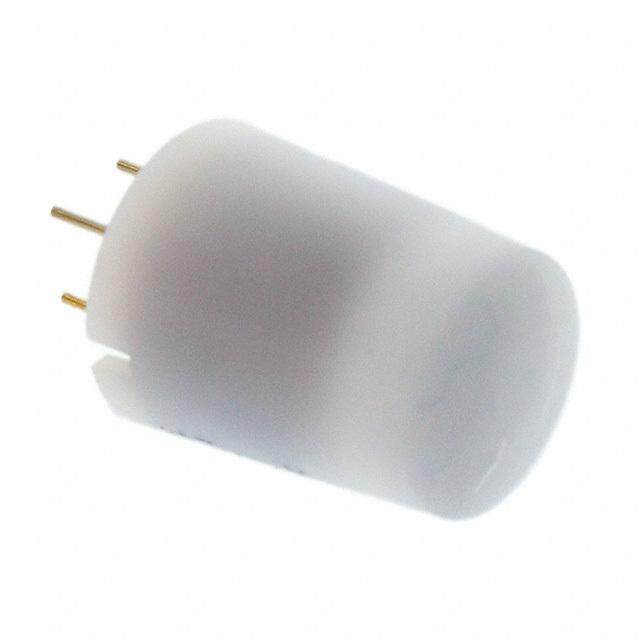
| 特性 | 聚乙烯,白色透镜 |
| 特色产品 | http://www.digikey.com/cn/zh/ph/Panasonic/NaPiOn.html |
| 电压-电源 | 3 V ~ 6 V |
| 电源电压-最大 | 6 V |
| 电源电压-最小 | 3 V |
| 电源电流 | 170 uA |
| 触发器类型 | 内部 |
| 输出类型 | 数字 |


- 商务部:美国ITC正式对集成电路等产品启动337调查
- 曝三星4nm工艺存在良率问题 高通将骁龙8 Gen1或转产台积电
- 太阳诱电将投资9.5亿元在常州建新厂生产MLCC 预计2023年完工
- 英特尔发布欧洲新工厂建设计划 深化IDM 2.0 战略
- 台积电先进制程称霸业界 有大客户加持明年业绩稳了
- 达到5530亿美元!SIA预计今年全球半导体销售额将创下新高
- 英特尔拟将自动驾驶子公司Mobileye上市 估值或超500亿美元
- 三星加码芯片和SET,合并消费电子和移动部门,撤换高东真等 CEO
- 三星电子宣布重大人事变动 还合并消费电子和移动部门
- 海关总署:前11个月进口集成电路产品价值2.52万亿元 增长14.8%

PDF Datasheet 数据手册内容提取
MP MOTION SENSOR 2002.10.23 7:56 PM Page 2 MP Motion Sensor (AMN1) MP MOTION MOTION SENSOR SENSOR (PASSIVE INFRARED TYPE) ‘ ’ NaPiOn web page URL: FEATURES http://www.napion.com/ 1. The world’s smallest with a built-in 5. Detects even slight motion of a per- amplifier son Extremely compact. Ideal for use in With our sensor, even slight motions miniaturized devices. made by people will be detected easily. 2. Dual lens colors (white and black) • Fine motion detection capability within are provided approximately 2 meters of sensor. With an ultrasmall design and dual lens Standard type: Detects movement of approximately colors (white and black), it is inconspicu- 30cm 11.811inch. ous, allowing the user to select either Slight motion detection type: white or black to match the equipment Detects movement of approximately color. This provides greater flexibility in 20cm 7.874inch. equipment design. 6. Noise withstanding capability Standard type Slight motion 3. Both digital output and analog out- Circuitry is contained in a TO5 metal detection type put (with adjustable sensitivity) are package, providing at least twice the available. noise withstanding capability as conven- 4. Built-in amplifier for easy use tional type. Has a built-in amplifier, and can be con- • Comparison example of noise withstand- nected directly to a microcomputer. ing capability • Block diagram of the digital output circuit Distance at which motion TO5 metal package sensor is not affected (9.8mm · 9mm .386inch · .354inch dia.) by cellular phone noise Spot type 10 m detection type Infrared Conventional type Min. 1 to 2m 3.281 to 6.562ft radiation Single-chip IC Stabilized MP Motion Sensor Min. 1 to 2cm .394 to .787inch power Vdd What is passive infrared type? supply APPLICATIONS This sensor detects changes in infrared radiation which owchcicuhr wish deinff ethreenret inis tmemovpeemraetunrt eb yfr oam p ethrseo snu (roror uonbdjeincgt)s . Multi lens Acmirpcluifiiter Coomcuirptcpauuriatttor OGuntdput 1. Home appliances Useful for saving energy in air conditioner, Q As this sensor detects temperature differences, it is Quad type well suited to detecting the motion of people by their PIR element television, personal computer, or ventilator Optical filter body temperature. and air purifier W Wide sensing area. 2. Amusement machine market • Block diagram of the analog output circuit Sensor Useful for saving energy and for automated T(9O.85m mme t·a l9 pmamck .a3g8e6inch · .354inch dia.) guidance in theme parks and large video games Infrared Infrared radiation radiation Single-chip 3. Equipment in service market Temperature difference rIandfriaartieodn IC Stspauobpwilpiezlyred Vdd Uansneofuuln fcoer mauetnotms aatnedd egnueidrgayn csea,v ainugto inm vaetendding machines, ATMs, etc. Movement Amplifier Output 4. Lighting market Multi lens circuit Gnd Automated on/off controls, etc. for lamps, QPIuRa de letympeent desk lamps, indoor lights, halls, stairway Optical filter lights, etc. ORDERING INFORMATION AMN 1 1 Output 1: Digital output 2: Analog output Detection performance 1: Standard detection type 2: Slight motion detection type 3: Spot detection type 4: 10m detection type Feature 1: PC board mounting type Operating voltage 1: 5V DC Lens color 1: Black 2: White 2
MP MOTION SENSOR 2002.10.23 7:56 PM Page 3 MP Motion Sensor (AMN1) PRODUCT TYPES 1. Digital output Packing quantity Rated operating voltage Detection performance Ambient temperature Lens color Part No. Inner Outer Black AMN11111 Standard detection type White AMN11112 Slight motion Black AMN12111 detection type White AMN12112 3 to 6 V DC –20 to +60°C –4 to +140°F 50 pcs. 1,000 pcs. Black AMN13111 Spot detection type White AMN13112 Black AMN14111 10m detection type White AMN14112 2. Analog output Packing quantity Rated operating voltage Detection performance Ambient temperature Lens color Part No. Inner Outer Black AMN21111 Standard detection type White AMN21112 Slight motion Black AMN22111 detection type White AMN22112 4.5 to 5.5 V DC –20 to +60°C –4 to +140°F 50 pcs. 1,000 pcs. Black AMN23111 Spot detection type White AMN23112 Black AMN24111 10m detection type White AMN24112 PERFORMANCE 1. Detection performance Standard Slight motion Spot detection 10m detection Items Conditions of objects to be detected detection type detection type type type 1. Detectable difference in temperature between the target Rated detection 5m 16.404ft 2m 6.562ft 5m 16.404ft 10m 32.808ft and background for the spot type is more than 4°C 39.2°F. distance*Remark 1 (Max.) (Max.) (Max.) (Max.) 2. Movement speed • Standard detection type/Spot detection type/ Horizontal*Remark 2 100° 91° 38° 110° 10m detection type: 1.0 m/s DetectionVertical*Remark 2 82° 91° 22° 93° 3. •D Seltiegchtti omno otibojne cdt e=t ehcutimona nty bpoed: y0 .(5s imze/ sis 700mm · 250mm range 27.559inch · 9.843inch, but for the slight motion detection Detection zone*Remark 3 64 zones 104 zones 24 zones 80 zones type the size is 200mm · 200mm 7.874inch · 7.874inch) 2. *Remarks1. Depending on the difference in temperature between the Vertical Vertical background and detection target and the speed at which the target moves, these sensors may be capable of detection Horizontal Horizontal beyond the detection distances stated above. Nevertheless, they should be used within the prescribed detection distances. Cut out Cut out For further details, refer to the detection range diagram on page 5. 3. Regarding of detection zone, please refer to “DETECTION (Standard detection/ (Spot detection type/ PERFORMANCE” on page 5. Slight motion detection type) 10 m detection type) 2. Rating (Measuring condition: ambient temp. = 25°C 77°F) (Common to All types) Items Specified value Remarks Power supply voltage –0.3 to 7 V DC Usable ambient temperature –20 to 60°C –4 to +140°F No freezing and condensing at low temperature. Storage temperature –20 to 70°C –4 to +158°F 3. Electrical characteristics (Measuring condition: ambient temp. = 25°C 77°F; operating voltage = 5V) (Common to All types) 1) Digital output Items Symbol Specified value Measured conditions Minimum 3.0 V DC Reted operating voltage Typical Vdd — Maximum 6.0 V DC Reted consumption current Typical 170 µA Iw Iout = 0 (Standby) *Remark Maximum 300 µA Current Maximum Iout 100 µA Vout 7Vdd–0.5 Output Minimum Vdd –0.5 Open when not detect- (when detecting) Voltage Vout Maximum Vdd (Same as operating voltage) ing Typical 7 s Circuit stability time Twu Maximum 30 s Remark: The current which is consumed during detection consists of the standby consumed current plus the output current. 3
MP MOTION SENSOR 2002.10.23 7:56 PM Page 4 MP Motion Sensor (AMN1) 2) Analog output Items Symbol Specified value Measured conditions Minimum 4.5 V DC Reted operating voltage Vdd Maximum 5.5 V DC Typical 0.17 mA Reted consumption current Iw Iout = 0 Maximum 0.3 mA Output current Maximum Iout 50 µA Minimum 0 V Output voltage Typical Vout 2.5 V Maximum Vdd Minimum 2.3 V Steady-state output Output offset average voltage Typical Voff 2.5 V voltage when not Maximum 2.7 V detecting Typical 130 m Vp-p Steady-state noise Vn Maximum 300 m Vp-p Circuit stability time Maximum Twu 45 s Note: To set to the same detection performance as the digital type, set the output voltage to the offset voltage (2.5V) ±0.45V (i.e. 2.95V or more and 2.05V or less). [Timing chart] 1) Digital output ON Power supply OFF Detect Detection state Not detect ON Sensor output OFF Circuit stability time Remark:Circuit stability time: 45s max. While the circuitry is stabilizing after the power is turned on, the sensor output is not fixed in the “on” state or “off” state. This is true regardless of whether or not the sensor has detected anything. 2) Analog output Vdd Power supply GND Detect Detection state (Comparator Not decision output) detect Body movement Vdd Threshold voltage 1 Output waveform (comparator) V out Voff V h V n GND V l Circuit stability time Threshold voltage 2 (comparator) Remark:Circuit stability time: 30s max. While the circuitry is stabilizing after the power is turned on, the sensor output is not fixed in the “on” state or “off” state. This is true regardless of whether or not the sensor has detected anything. 4
MP MOTION SENSOR 2002.10.23 7:56 PM Page 5 MP Motion Sensor (AMN1) DETECTION PERFORMANCE 1. Standard detection type TOP VIEW SIDE VIEW 5m X 5m Y 16.404ft 50° 16.404ft 41° 2.5m 2.5m 8.202ft 8.202ft 0° 0° 2.5m 2.5m 8.202ft 8.202ft 41° 50° 5m 5m 16.404ft 16.404ft X-Y cross section Y Detection zone 3m 9.843ft 2 6.562 1 3.281 (M(Maaxx. .1 58..6567m0f)t) Remarks: 1. The X-Y cross-sectional diagram shows the detection area. 2. The differences in the detection zone patterns are indicative of the projec- X 4m 3 2 1 1 2 3 4m tions of the 16 lenses with single focal point and with five optical axes. An 13.123ft 9.843 6.562 3.281 3.281 6.562 9.843 13.123ft object whose temperature differs from the background temperature and 1 which crosses inside the detection zone will be detected. 3.281 2 6.562 3m 9.843ft (Max. 7.42m) (Max. 24.344ft) 2. Slight motion detection type X-Y cross section Y 28..52m02ft Detection zone Y 2.5m 2 8.202ft 46° 6.562 6.5622 4.912.51 1.5 1 4.921 3.281 1 0.5 3.281 1.640 0.5 1.640 X –2.5m –2 –1.5 –1 –0.5 0.5 1 1.5 2 2.5m 0 13m.281ft 26m.562ft 0° –8.202ft –6.562–4.921–3.281–1.–614–.0604.50 1.640 3.281 4.921 6.562 8.202ft –0.5 –1 –1.640 –3.281 –1 –1.5 –3.281 –4.921 –1.5 –2 –4.921 –6.562 –2 –6.562 –2.5m 46° –8.202ft –2.5m –8.202ft 1m 2m (Max. 5m dia.) 3.281ft 6.562ft (Max. 16.404ft dia.) Remarks: 1. The X-Y cross-sectional diagram shows the detection area. 2. The differences in the detection zone patterns are indicative of the projections of the 26 lenses with single focal point and with three optical axes. An object whose temperature differs from the background temperature and which crosses inside the detection zone will be detected. 5
MP MOTION SENSOR 2002.10.23 7:56 PM Page 6 MP Motion Sensor (AMN1) 3. Spot detection type X-Y cross section TOP VIEW SIDE VIEW Y X Y 2.5 2.5 1m 8.202 8.202 3.281ft 19° 1.25 1.25 0.5 4.101 4.101 11° 1.640 0 28..5202 51m6.404ft 0° 0 28..5202 51m6.404ft 0° 3.21m81ft 1.06.540 1.06.540 3.21m81Xft ((MMaaxx.. 14..45m93)ft) 1.25 1.25 11° 0.5 4.101 4.101 1.640 19° 2.5m 2.5m 1m 8.202ft 2m 5m 8.202ft 2m 5m 3.281ft 5.562ft 16.404ft 5.562ft 16.404ft (M(aMxa. x6.. 526m2)ft) Remarks: 1. The X-Y cross-sectional diagram shows the detection area. 2. The differences in the detection zone patterns are indicative of the projections of the 6 lenses with single focal point and with two optical axes. An object whose temperature differs from the background temperature and which crosses inside the detection zone will be detected. 4. 10m detection type TOP VIEW SIDE VIEW 10m X 10m Y 32.808ft 32.808ft 46.5° 5m 5m 16.404ft 16.404ft 5m 5m 16.404ft 16.404ft 55° 10m 10m 32.808ft 32.808ft X-Y cross section Y Detection zone (15.9m 52.165ft) 6m 19.685ft 4 13.123 2 6.562 X 10m 8 6 4 2 2 4 6 8 10m 32.808ft26.24719.685 13.123 6.562 6.562 13.123 19.685 26.24732.808ft 2 6.562 Remarks: 1. The X-Y cross-sectional diagram shows the detection area. 2. The differences in the detection zone patterns are indicative of the projec- 13.1243 (12.3m 40.354ft) toiobnjesc ot fw thhoes 2e0 t elemnpseersa wtuirteh dsiinffgelres fforocmal tphoein bt aacnkdg rwoiuthn dfi vteem oppeticraatlu arexe asn. dAn which crosses inside the detection zone will be detected. 6m 19.685ft 5. Notes regarding the detection zone The detection zone has the polarity shown in the diagram on the right. When targets enter both the + and – zones with the same timing, the Target signals are cancelled each other, thus in this case there is a possibility that the object cannot be detected at the maximum specified detection distance. Detection zone 6
MP MOTION SENSOR 2002.10.23 7:56 PM Page 7 MP Motion Sensor (AMN1) HOW TO USE 1. Wiring diagram 1) Digital output 2) Analog output Sensor Vdd Sensor Vdd + GND Load GND + Microcomputer, Out OP Out AMP A/D converter etc. Iout: Max.100 µA Vdd: Input power source (DC) GND:GND Out: Output (Comparator) 2. Timer circuit example 1) Digital output 2) Analog output Input voltage 10 µ + 5RVEG 47 µ + (5VDC) Vdd Input voltage 10 µ + 5RVEG 47 µ + (5VDC) Vdd 0.1 µ 0.1 µ 0.1 µ 0.1 µ 0.1 µ 0.1 µ GND GND 47k 10k Connection Relay 10 µ + 0.1 µ tsoe nmsootrion Relay 1407 µk + 0.1 µ 10k Ctsoeo nmnsnooetricotnion 3 2 16 Tttdsuhoehremten es secte rttoahnsnnisn sowgirsh teonr 13714211H3901C 115 RC 0.1 µ Out Tttdsuhoehremten es secte rttoahnsnnisn sowgirsh teonr 1713342H31129C0116151 R 0.1 µ Window Out 14 GND C comparator 8 14 Select a transistor 8 to match the relay Timer IC Timer time = RXC Straenlescist tao r GND to match Timer IC Timer time = RXC the relay Note: This is the reference circuit which drives the MP motion sensor. Install a Note: This circuit is a sample of a drive circuit for the MP Motion Sensor. Its noise filter for applications requiring enhanced detection reliability and noise resistance and long-term reliability are not considered or investigat- noise withstanding capability. ed. Differences in the specifications of electronic components to which the To improve the detection reliability and noise resistance of the circuit, units are connected sometimes affect their correct operation; please consider adding a noise filter. check the units' performance and reliability for each application. Matsushita Electric Works, Ltd. accepts no responsibility for damages resulting from the use of this circuit. 3. Installation X direction m Install the sensor so that people will be entering from the X or Y direc- tion shown below. If persons approch the sensor from the Z direction, detection distance will be shortened. Y direction m Z Z direction D X direction m 7
MP MOTION SENSOR 2002.10.23 7:56 PM Page 8 MP Motion Sensor (AMN1) DIMENSIONS mm inch General tolerance ±0.5 ±.020 1. Standard detection type Recommended PC board pattern (BOTTOM VIEW) .31904 + +00 ..020 0d 8 idai.a. Sensing area Note 2) 9.5 dia. Molding gate .374 dia. 11.0 3.5 Notes 3) .433 .138 Note 1) 14.5 11.571 .433 .00.1485––.00.0025 ddiiaa.. 4.5 .177 45° 5.2.008–0–0..010 4d idai.a. .41313 d diaia.. 45° 33--.002.665 + 0+. 000 0. 14 ddiiaa.. OUT GND Notes:1. In order to ensure proper detection, install it with the lens exposed at least 3.5mm .138inch. 2. As for panel mounting hole, tapering or making a P.C.D. 5.08–0.2 dia. large size hole should be done. .200–.008 dia. 3. The height dimension does not include the remain- Vdd ing molding gate. 45°–4° 45°–4° 2. Slight motion detection type Recommended PC board pattern (BOTTOM VIEW) .1428.84 + + .0 000 0. 2 8 ddiiaa.. Sensing area Note 2) 12.7 dia. .500 dia. Molding gate 1.416.99 ddiiaa..7.4 dia. 1.520.84 .20.944 .291 dia. Note 3) Note 1) 15.2 .598 12.8 .83.590.504 45° 5.2.008–0–0..010 4d idai.a. .00.1485––.00.0025 ddiiaa.. 4.5 .177 45° 33--.002.665 + 0+. 000 0. 14 ddiiaa.. 11 dia. .433 dia. OUT GND Notes:1. In order to ensure proper detection, install it with the lens exposed at least 2.4mm .094inch. 2. As for panel mounting hole, tapering or making a P.C.D. 5.08–0.2 dia. large size hole should be done. Vdd .200–.008 dia. 3. The height dimension does not include the remaining molding gate. 45°–4° 45°–4° 8
MP MOTION SENSOR 2002.10.23 7:56 PM Page 9 MP Motion Sensor (AMN) 3. Spot detection type 4. 10m detection type mm inch General tolerance ±0.5 ±.020 Recommended PC board pattern Recommended PC board pattern (BOTTOM VIEW) (BOTTOM VIEW) .397.40+-+0-00..0208ddiiaa.. Note 1) .1770.59-+-+00.00.028ddiiaa.. Note 2) 8.9 dia. Note 2) Molding gate .350 dia. 17.4 dia. 12.9 .685 dia. .508 15.1 Mgaotleding 1.677.00 ddiiaa.. Note 3) .594 0.0.4158––0.0.0052ddiiaa.. 4.1.577 4°5 5..2008–0–0..1004didai.a. .41313 4°5 5..2008–0–0..1004didai.a. 8.3.639 1.783.503 °54 33--.00.2665-+0-+.0000.14ddiiaa.. OUT GND °54 33--.00.2665-+0-+.0000.14ddiiaa.. 0.0.4158––0.0.0052ddiiaa.. 4.1.577 Sensing area P.C.D. 5.08–0.2dia. 11 dia. Vdd .200–.008dia. .433 dia. 5.6 OUT GND Note 1) 45°–4° 45°–4° P.C.D. 5.08–0.2dia. Vdd .200–.008dia. Notes: 1. As for panel mounting hole, tapering or making a large size hole should be done. Notes: 2. The height dimension does not include the remaining molding gate. 1. In order to ensure proper detection, install it with the lens exposed at least 5.6mm .220inch. 45°–4° 45°–4° 2. Ahosl efo sr hpoaunledl bmeo duonntien.g hole, tapering or making a large size 3. The height dimension does not include the remaining mold- ing gate. NOTES 1. Checkpoints relating to principle of 2) When the heat source inside the 5) Do not attempt to clean the sensor. operation detection range hardly moves or when it Cleaning fluid may enter inside the lens MP motion sensors are passive infrared moves at high speed; for details on the area causing a deterioration in perfor- sensors which detect changes in the movement speed, refer to the section on mance. infrared rays. They may fail to detect the performance ratings. 6) When using the sensors with cables, it successfully if a heat source other than a 2. When the detection area becomes is recommended that cables which are human being is detected or if there are larger shielded and as short as possible be no temperature changes in or movement When the difference between the ambi- used in order to safeguard against the of a heat source. Care must generally be ent temperature and body temperature is effects of noise. taken in the following cases. The perfor- large (more than 20°C 68°F), detection mance and reliability of the sensors must may occur in isolated areas outside the For the general precautions, refer to the be checked out under conditions of actu- specified detection range. Notes for Motion Sensors on page 22. al use. 3. Other handling cautions <1> Cases where a heat source other 1) Be careful not to allow dust or dirt to than a human being is detected. accumulate on the lens as this will 1) When a small animal enters the detec- adversely affect the detection sensitivity. tion range. 2) The lens is made of a soft material 2) When the sensor is directly exposed (polyethylene). to sunlight, a vehicle’s headlights, an Avoid applying a load or impact since incandescent light or some other source this will deform or scratch the lens, mak- of far infrared rays. ing proper operation impossible and 3) When the temperature inside the causing a deterioration in its perfor- detection range has changed suddenly mance. due to the entry of cold or warm air from 3) The sensor may be damaged if it is an air-conditioning or heating unit, water exposed to static with a voltage exceed- vapor from a humidifier, etc. ing ±200V. Therefore, do not touch its <2> Cases where it is difficult to terminals directly, and exercise adequate detect the heat source care in the handling of the sensor. 1) When an object made of glass, acrylic 4) When the leads are to be soldered, or other subject which far infrared rays solder them by hand for less than 3 sec- have difficulty passing through is located onds at a temperature of less than 350°C between the sensor and what is to be 662°Fat the tip of the soldering iron. detected. Avoid using a solder bath since this will causing a deterioration in the sensor’s performance. 12/1/2002 All Rights Reserved, © Copyright Matsushita Electric Works, Ltd.