ICGOO在线商城 > 集成电路(IC) > 线性 - 放大器 - 仪表,运算放大器,缓冲器放大器 > AD8627ARZ
 Datasheet下载
- 型号: AD8627ARZ
- 制造商: Analog
- 库位|库存: xxxx|xxxx
- 要求:
| 数量阶梯 | 香港交货 | 国内含税 |
| +xxxx | $xxxx | ¥xxxx |
查看当月历史价格
查看今年历史价格
AD8627ARZ产品简介:
ICGOO电子元器件商城为您提供AD8627ARZ由Analog设计生产,在icgoo商城现货销售,并且可以通过原厂、代理商等渠道进行代购。 AD8627ARZ价格参考¥18.57-¥34.41。AnalogAD8627ARZ封装/规格:线性 - 放大器 - 仪表,运算放大器,缓冲器放大器, J-FET 放大器 1 电路 满摆幅 8-SOIC。您可以下载AD8627ARZ参考资料、Datasheet数据手册功能说明书,资料中有AD8627ARZ 详细功能的应用电路图电压和使用方法及教程。
AD8627ARZ 是由 Analog Devices Inc.(亚德诺半导体公司)生产的一款低噪声、低功耗的 CMOS 运算放大器,属于线性放大器系列中的仪表、运算放大器和缓冲器放大器类别。其主要应用场景包括:

1. 精密信号调理
   AD8627ARZ 的低输入偏置电流和低失调电压特性使其非常适合用于需要高精度信号处理的应用场景,例如传感器信号放大。它可以将微弱的传感器输出信号(如温度传感器、压力传感器或生物医学信号)进行精确放大,同时保持信号的完整性。

2. 医疗设备
   在医疗领域,AD8627ARZ 可用于心电图(ECG)、脑电图(EEG)等生物医学信号的采集与放大。由于其低噪声和高共模抑制比(CMRR),能够有效减少干扰信号的影响,确保采集到的生理信号准确可靠。

3. 工业自动化
   在工业控制系统中,AD8627ARZ 常用于信号链中的前端信号放大。例如,在数据采集系统中,它可用于放大来自各种传感器(如加速度计、应变计或热电偶)的微弱信号,以便后续数字化处理。

4. 音频信号处理
   由于其低失真和低噪声性能,AD8627ARZ 可用作音频信号的前置放大器,适用于便携式音频设备或其他对音质要求较高的应用场合。

5. 电池供电设备
   AD8627ARZ 的低功耗特性使其成为电池供电设备的理想选择。例如,在无线传感器节点或便携式测量仪器中,它可以在保证性能的同时延长电池使用寿命。

6. 通信系统
   在通信设备中,AD8627ARZ 可用于信号接收端的低噪声放大,帮助提高信噪比,从而改善系统的整体性能。

总结来说,AD8627ARZ 凭借其低噪声、低功耗和高精度的特点,广泛应用于精密测量、医疗电子、工业控制、音频处理以及电池供电设备等领域。这些应用场景对其性能要求较高,而 AD8627ARZ 能够满足这些需求并提供稳定可靠的解决方案。
| 参数 | 数值 |
| -3db带宽 | - |
| 产品目录 | 集成电路 (IC)半导体 |
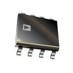
| 描述 | IC OPAMP JFET 5MHZ RRO 8SOIC精密放大器 Prec Low Pwr JFET SGL-Supply |
| 产品分类 | Linear - Amplifiers - Instrumentation, OP Amps, Buffer Amps集成电路 - IC |
| 品牌 | Analog Devices Inc |
| 产品手册 | |
| 产品图片 |
|
| rohs | 符合RoHS无铅 / 符合限制有害物质指令(RoHS)规范要求 |
| 产品系列 | 放大器 IC,精密放大器,Analog Devices AD8627ARZ- |
| 数据手册 | |
| 产品型号 | AD8627ARZ |
| 产品培训模块 | http://www.digikey.cn/PTM/IndividualPTM.page?site=cn&lang=zhs&ptm=30008http://www.digikey.cn/PTM/IndividualPTM.page?site=cn&lang=zhs&ptm=26202 |
| 产品目录页面 | |
| 产品种类 | 精密放大器 |
| 供应商器件封装 | 8-SOIC N |
| 共模抑制比—最小值 | 105 dB |
| 关闭 | No |
| 包装 | 管件 |
| 压摆率 | 5 V/µs |
| 双重电源电压 | 2.5 V to 13 V |
| 可用增益调整 | 107 dB |
| 商标 | Analog Devices |
| 增益带宽生成 | 5 MHz |
| 增益带宽积 | 5MHz |
| 安装类型 | 表面贴装 |
| 安装风格 | SMD/SMT |
| 封装 | Tube |
| 封装/外壳 | 8-SOIC(0.154",3.90mm 宽) |
| 封装/箱体 | SOIC-8 |
| 工作温度 | -40°C ~ 85°C |
| 工作电源电压 | 5 V to 26 V |
| 工厂包装数量 | 98 |
| 放大器类型 | J-FET |
| 最大双重电源电压 | 13 V |
| 最大工作温度 | + 85 C |
| 最小双重电源电压 | 2.5 V |
| 最小工作温度 | - 40 C |
| 标准包装 | 98 |
| 电压-电源,单/双 (±) | 5 V ~ 26 V, ±2.5 V ~ 13 V |
| 电压-输入失调 | 350µV |
| 电压增益dB | 107.23 dB |
| 电流-电源 | 710µA |
| 电流-输入偏置 | 0.25pA |
| 电流-输出/通道 | 15mA |
| 电源电压-最大 | 26 V |
| 电源电压-最小 | 5 V |
| 电源电流 | 710 uA |
| 电源类型 | Single, Dual |
| 电路数 | 1 |
| 系列 | AD8627 |
| 视频文件 | http://www.digikey.cn/classic/video.aspx?PlayerID=1364138032001&width=640&height=505&videoID=2245193153001http://www.digikey.cn/classic/video.aspx?PlayerID=1364138032001&width=640&height=505&videoID=2245193159001 |
| 设计资源 | |
| 转换速度 | 5 V/us |
| 输入偏压电流—最大 | 60 pA |
| 输入电压范围—最大 | 11 V |
| 输入补偿电压 | 0.35 mV |
| 输出电流 | 15 mA |
| 输出类型 | 满摆幅 |
| 通道数量 | 1 Channel |


- 商务部:美国ITC正式对集成电路等产品启动337调查
- 曝三星4nm工艺存在良率问题 高通将骁龙8 Gen1或转产台积电
- 太阳诱电将投资9.5亿元在常州建新厂生产MLCC 预计2023年完工
- 英特尔发布欧洲新工厂建设计划 深化IDM 2.0 战略
- 台积电先进制程称霸业界 有大客户加持明年业绩稳了
- 达到5530亿美元!SIA预计今年全球半导体销售额将创下新高
- 英特尔拟将自动驾驶子公司Mobileye上市 估值或超500亿美元
- 三星加码芯片和SET,合并消费电子和移动部门,撤换高东真等 CEO
- 三星电子宣布重大人事变动 还合并消费电子和移动部门
- 海关总署:前11个月进口集成电路产品价值2.52万亿元 增长14.8%


PDF Datasheet 数据手册内容提取
Precision Low Power Single-Supply JFET Amplifiers Data Sheet AD8625/AD8626/AD8627 FEATURES PIN CONFIGURATIONS SC70 package 8-Lead SOIC 5-Lead SC70 (R-8 Suffix) (KS Suffix) Very low I : 1 pA max B Single-supply operation: 5 V to 26 V OUT A 1 5 V+ NC 1 8 NC Dual-supply operation: ±2.5 V to ±13 V V– 2 AD8627 –IN 2 7 V+ Rail-to-rail output AD8627 +IN 3 4 –IN Low supply current: 630 μA/amp typ +IN 3 6 OUT Low offset voltage: 500 μV max V– 4 5 NC Unity gain stable NC = NO CONNECT No phase reversal 8-Lead SOIC 8-Lead MSOP (R-8 Suffix) (RM-Suffix) APPLICATIONS OUT A 1 8 V+ OUT A 1 8 V+ Photodiode amplifiers –IN A OUT B ATEs –IN A 2 7 OUT B +IN A AD8626 –IN B AD8626 V– 4 5 +IN B Line-powered/battery-powered instrumentation +IN A 3 6 –IN B Industrial controls V– 4 5 +IN B Automotive sensors Precision filters Audio 14-Lead SOIC 14-Lead TSSOP (R-Suffix) (RU-Suffix) OUT A 1 14 OUT D OUT A 1 14 OUT D –IN A –IN D –IN A 2 13 –IN D +IN A +IN D +IN A 3 12 +IN D V+ AD8625 V– AD8625 +IN B +IN C V+ 4 11 V– –IN B –IN C +IN B 5 10 +IN C OUT B 7 8 OUT C O–UINT BB 67 98 O–IUNT C C 03023-001 Figure 1. GENERAL DESCRIPTION The AD862x is a precision JFET input amplifier. It features The 5 MHz bandwidth and low offset are ideal for precision filters. true single-supply operation, low power consumption, and The AD862x is fully specified over the industrial temperature rail-to-rail output. The outputs remain stable with capacitive range. (−40°C to +85°C). The AD8627 is available in both loads of over 500 pF; the supply current is less than 630 μA/amp. 5-lead SC70 and 8-lead SOIC surface-mount packages (SC70 Applications for the AD862x include photodiode transimpedance packaged parts are available in tape and reel only). The AD8626 amplification, ATE reference level drivers, battery management, is available in MSOP and SOIC packages, while the AD8625 is both line powered and portable instrumentation, and remote available in TSSOP and SOIC packages. sensor signal conditioning, which includes automotive sensors. The AD862x’s ability to swing nearly rail-to-rail at the input and rail-to-rail at the output enables it to be used to buffer CMOS DACs, ASICs, and other wide output swing devices in single-supply systems. Rev. F Document Feedback Information furnished by Analog Devices is believed to be accurate and reliable. However, no responsibility is assumed by Analog Devices for its use, nor for any infringements of patents or other One Technology Way, P.O. Box 9106, Norwood, MA 02062-9106, U.S.A. rights of third parties that may result from its use. Specifications subject to change without notice. No license is granted by implication or otherwise under any patent or patent rights of Analog Devices. Tel: 781.329.4700 ©2003–2013 Analog Devices, Inc. All rights reserved. Trademarks and registered trademarks are the property of their respective owners. Technical Support www.analog.com
AD8625/AD8626/AD8627 Data Sheet TABLE OF CONTENTS Features .............................................................................................. 1 Typical Performance Characteristics ..............................................6 Applications ....................................................................................... 1 Applications Information .............................................................. 13 Pin Configurations ........................................................................... 1 Minimizing Input Current ........................................................ 15 General Description ......................................................................... 1 Photodiode Preamplifier Application...................................... 15 Revision History ............................................................................... 2 Output Amplifier for DACs ...................................................... 16 Specifications ..................................................................................... 3 Eight-Pole Sallen Key Low-Pass Filter ..................................... 17 Electrical Characteristics ............................................................. 3 Outline Dimensions ....................................................................... 18 Absolute Maximum Ratings ............................................................ 5 Ordering Guide .......................................................................... 20 ESD Caution .................................................................................. 5 REVISION HISTORY 5/13—Rev. E to Rev. F 1/04—Rev. A to Rev. B Changes to Applications Information Section ............................ 13 Change to General Description ....................................................... 1 Changes to Ordering Guide .......................................................... 20 Change to Figure 10 .......................................................................... 7 Change to Figure13 ........................................................................... 7 12/10—Rev. D to Rev. E Change to Figure 37 ....................................................................... 11 Removed Table Summary Conditions Above Table 3 ................. 5 Changes to Figure 38 ...................................................................... 12 Updated Outline Dimensions ....................................................... 18 Change to Output Amplifier for DACs Section ......................... 15 3/09—Rev. C to Rev. D Updated Outline Dimensions ....................................................... 19 Updated Outline Dimensions ....................................................... 18 10/03—Rev. 0 to Rev. A Changes to Ordering Guide .......................................................... 19 Addition of Two New Parts ............................................... Universal 11/04—Rev. B to Rev. C Change to General Description ....................................................... 1 Changes to Pin Configurations ....................................................... 1 Updated Figure Codes ....................................................... Universal Change to Specifications Table ........................................................ 3 Changes to Figure 17 and 18 ........................................................... 8 Changes to Figure 31 ...................................................................... 10 Changes to Figure 33 and Figure 37 ............................................. 11 Changes to Figure 32 ...................................................................... 11 Changes to Figure 38 ...................................................................... 12 Changes to Figure 38 ...................................................................... 12 Changes to Figure 39 and Figure 40 ............................................. 13 Changes to Figure 46 ...................................................................... 16 Changes to Figure 41 to Figure 44 ................................................ 14 Changes to Figure 47 ...................................................................... 16 Changes to Figure 49 ...................................................................... 17 Updated Outline Dimensions ....................................................... 18 Changes to Ordering Guide .......................................................... 19 Rev. F | Page 2 of 20
Data Sheet AD8625/AD8626/AD8627 SPECIFICATIONS ELECTRICAL CHARACTERISTICS @V = 5 V, V = 1.5 V, T = 25°C, unless otherwise noted. S CM A Table 1. Parameter Symbol Conditions Min Typ Max Unit INPUT CHARACTERISTICS Offset Voltage V 0.05 0.5 mV OS −40°C < T < +85°C 1.2 mV A Input Bias Current I 0.25 1 pA B –40°C < T < +85°C 60 pA A Input Offset Current I 0.5 pA OS –40°C < T < +85°C 25 pA A Input Voltage Range 0 3 V Common-Mode Rejection Ratio CMRR V = 0 V to 2.5 V 66 87 dB CM Large Signal Voltage Gain A R = 10 kΩ, V = 0.5 V to 4.5 V 100 230 V/mV VO L O Offset Voltage Drift ∆V /∆T –40°C < T < +85°C 2.5 µV/°C OS A OUTPUT CHARACTERISTICS Output Voltage High V 4.92 V OH I = 2 mA, –40°C < T < +85°C 4.90 V L A Output Voltage Low V 0.075 V OL I = 2 mA, –40°C < T < +85°C 0.08 V L A Output Current I ±10 mA OUT POWER SUPPLY Power-Supply Rejection Ratio PSRR V = 5 V to 26 V 80 104 dB S Supply Current/Amplifier I 630 785 µA SY –40°C < T < +85°C 800 µA A DYNAMIC PERFORMANCE Slew Rate SR 5 V/µs Gain Bandwidth Product GBP 5 MHz Phase Margin Ø 60 Degrees M NOISE PERFORMANCE Voltage Noise e p-p 0.1 Hz to 10 Hz 1.9 µV p-p n Voltage Noise Density e f = 1 kHz 17.5 nV/√Hz n Current Noise Density i f = 1 kHz 0.4 fA/√Hz n Channel Separation C f = 1 kHz 104 dB s Rev. F | Page 3 of 20
AD8625/AD8626/AD8627 Data Sheet @V = ±13 V; V = 0 V; T = 25°C, unless otherwise noted. S CM A Table 2. Parameter Symbol Conditions Min Typ Max Unit INPUT CHARACTERISTICS Offset Voltage V 0.35 0.75 mV OS –40°C < T < +85°C 1.35 mV A Input Bias Current I 0.25 1 pA B –40°C < T < +85°C 60 pA A Input Offset Current I 0.5 pA OS –40°C < T < +85°C 25 pA A Input Voltage Range –13 +11 V Common-Mode Rejection Ratio CMRR V = –13 V to +10 V 76 105 dB CM Large Signal Voltage Gain A R = 10 kΩ, V = –11 V to +11 V 150 310 V/mV VO L O Offset Voltage Drift ∆V /∆T –40°C < T < +85°C 2.5 µV/°C OS A OUTPUT CHARACTERISTICS Output Voltage High V +12.92 V OH V I = 2 mA, –40°C < T < +85°C +12.91 V OH L A Output Voltage Low V –12.92 V OL V I = 2 mA, –40°C < T < +85°C –12.91 V OL L A Output Current I ±15 mA OUT POWER SUPPLY Power-Supply Rejection Ratio PSRR V = ±2.5 V to ±13 V 80 104 dB S Supply Current/Amplifier I 710 850 µA SY –40°C < T < +85°C 900 µA A DYNAMIC PERFORMANCE Slew Rate SR 5 V/µs Gain Bandwidth Product GBP 5 MHz Phase Margin Ø 60 Degrees M NOISE PERFORMANCE Voltage Noise e p-p 0.1 Hz to 10 Hz 2.5 µV p-p n Voltage Noise Density e f = 1 kHz 16 nV/√Hz n Current Noise Density i f = 1 kHz 0.5 fA/√Hz n Channel Separation C f = 1 kHz 105 dB s Rev. F | Page 4 of 20
Data Sheet AD8625/AD8626/AD8627 ABSOLUTE MAXIMUM RATINGS θ is specified for worst-case conditions when devices are JA Table 3. soldered in circuit boards for surface-mount packages. Parameter Ratings Supply Voltage 27 V Table 4. Input Voltage VS– to VS+ Package Type θJA θJC Unit Differential Input Voltage ± Supply Voltage 5-Lead SC70 (KS) 376 126 °C/W Output Short-Circuit Duration Indefinite 8-Lead MSOP (RM) 210 45 °C/W Storage Temperature Range, R Package −65°C to +125°C 8-Lead SOIC (R) 158 43 °C/W Operating Temperature Range −40°C to +85°C 14-Lead SOIC (R) 120 36 °C/W 14-Lead TSSOP (RU) 180 35 °C/W Junction Temperature Range, R Package −65°C to +150°C Lead Temperature Range (Soldering, 60 sec) 300°C Stresses above those listed under Absolute Maximum Ratings ESD CAUTION may cause permanent damage to the device. This is a stress rating only; functional operation of the device at these or any other conditions above those indicated in the operational section of this specification is not implied. Exposure to absolute maximum rating conditions for extended periods may affect device reliability. Rev. F | Page 5 of 20
AD8625/AD8626/AD8627 Data Sheet TYPICAL PERFORMANCE CHARACTERISTICS 25 16 VTAS Y= = 25±°1C2V 14 VSY = +3.5V/–1.5V 20 MPLIFIERS 15 MPLIFIERS 1120 MBER OF A 10 MBER OF A 86 NU NU 4 5 0 03023-002 20 03023-005 –600 –400 –200 0 200 400 600 0 1 2 3 4 5 6 7 8 9 10 VOLTAGE (µV) OFFSET VOLTAGE (µV/°C) Figure 2. Input Offset Voltage Figure 5. Offset Voltage Drift 12 50 VSY =±13V 40 VTAS Y= = 25±°1C3V 10 30 RS A) E p 20 LIFI 8 NT ( P E 10 M R A R BER OF 6 BIAS CU–100 M 4 T U U–20 N P N I–30 2 0 03023-003 ––5400 03023-006 0 1 2 3 4 5 6 7 8 9 10 –15.0–12.5–10.0–7.5 –5.0 –2.5 0 2.5 5.0 7.5 10.0 12.5 15.0 OFFSET VOLTAGE (µV/°C) VCM (V) Figure 3. Offset Voltage Drift Figure 6. Input Bias Current vs. VCM 18 0 VSY = +3.5V/–1.5V VSY =±13V 16 –0.1 TA = 25°C 14 –0.2 RS A) E p LIFI 12 NT (–0.3 P E M 10 R–0.4 A R BER OF 8 BIAS CU–0.5 M 6 T –0.6 U U N P 4 IN–0.7 20 03023-004 ––00..98 03023-007 –400 –300 –200 –100 0 100 200 300 –15.0–12.5–10.0–7.5 –5.0 –2.5 0 2.5 5.0 7.5 10.0 12.5 15.0 VOLTAGE (µV) VCM (V) Figure 4. Input Offset Voltage Figure 7. Input Bias Current vs. VCM Rev. F | Page 6 of 20
Data Sheet AD8625/AD8626/AD8627 100 500 VSY =±13V VSY = 5V VCM = 0V 400 V) 300 S CURRENT (pA) 10 µSET VOLTAGE ( 1200000 A F–100 INPUT BI 1 INPUT OF––320000 0.1 03023-008 ––540000 03023-011 –50 –25 0 25 50 75 100 125 150 –1 0 1 2 3 4 TEMPERATURE (°C) VCM (V) Figure 8. Input Bias Current vs. Temperature Figure 11. Input Offset Voltage vs. VCM 2.0 10M VSY = +5V OR±5V 1.5 RENT (pA) 01..50 AIN (V/V) 1M VSY =±13V R G CU 0 OP VSY = +5V S O A L BI–0.5 N- NPUT –1.0 OPE100k I ––21..05 03023-009 10k 03023-012 –5 –4 –3 –2 –1 0 1 2 3 4 5 0.1 1 10 100 VCM (V) LOAD RESISTANCE (kΩ) Figure 9. Input Bias Current vs. VCM Figure 12. Open-Loop Gain vs. Load Resistance 1000 1000 VSY =±13V 900 a 800 V) d µTAGE ( 670000 N (V/mV) 100 cb ET VOL 450000 OP GAI e S O F L INPUT OF 123000000 OPEN- 10 cab... VVVSSSYYY === ±+±511V33VV, V,, VOVO O= ==+0±±.11511VVV/+,, 4RR.L5L V==, 12R0kLkΩ =Ω 2kΩ –1000 03023-010 1 de.. VVSSYY == ++55VV,, VVOO == ++00..55VV//++44..55VV,, RRLL == 61000kΩΩ 03023-013 –15 –12 –9 –6 –3 0 3 6 9 12 15 –40 25 95 125 VCM (V) TEMPERATURE (°C) Figure 10. Input Offset Voltage vs. VCM Figure 13. Open-Loop Gain vs. Temperature Rev. F | Page 7 of 20
AD8625/AD8626/AD8627 Data Sheet 600 10k 500 VSY =±13V VSY =±13V 400 V) µV) 300 RL = 10kΩ E (m 1k E ( AG VOLTAG 120000 RL = 100kΩ UT VOLT 100 T P E 0 T S U OFF–100 RL = 600Ω –O VOL SY 10 –200 V VOH ––430000 03023-014 1 03023-017 –15 –10 –5 0 5 10 15 0.001 0.01 0.1 1 10 100 OUTPUT VOLTAGE (V) LOAD CURRENT (mA) Figure 14. Input Error Voltage vs. Output Voltage for Resistive Loads Figure 17. Output Saturation Voltage vs. Load Current 250 10k 200 RL = 1kΩ VSY =±5V VSY = 5V POS RAIL 150 V) V) 100 RL = 10kΩ RL = 100kΩ E (m 1k µ G GE ( 50 LTA A O T V T VOL –500 RL = 10kΩ TPUT 100 INPU–100 RL = 1kΩ –OU VOL –150 NEG RAIL VSY 10 VOH ––225000 03023-015 1 03023-018 0 50 100 150 200 250 300 0.001 0.01 0.1 1 10 100 OUTPUT VOLTAGE FROM SUPPLY RAILS (mV) LOAD CURRENT (mA) Figure 15. Input Error Voltage vs. Output Voltage within 300 mV of Figure 18. Output Saturation Voltage vs. Load Current Supply Rails 800 70 315 VSY =±13V 700 60 RL = 2kΩ 270 +125°C 50 CL = 40pF 225 A) 600 µCENT CURRENT ( 345000000 +25°C –55°C GAIN (dB) 12340000 GAIN PHASE 4911503850 HASE (Degrees) S P UIE 0 –0 Q 200 –10 –45 1000 03023-016 ––3200 ––19305 03023-019 0 4 8 12 16 20 24 28 10k 100k 1M 10M 50M TOTAL SUPPLY VOLTAGE (V) FREQUENCY (Hz) Figure 16. Quiescent Current vs. Supply Voltage at Different Temperatures Figure 19. Open-Loop Gain and Phase Margin vs. Frequency Rev. F | Page 8 of 20
Data Sheet AD8625/AD8626/AD8627 70 315 140 VSY = 5V VSY =±13V 60 RL = 2kΩ 270 120 CL = 40pF 50 225 100 40 180 80 GAIN es) GAIN (dB) 123000 PHASE 9140355 HASE (Degre CMRR (dB) 246000 P 0 –0 0 –10 –45 –20 ––3200 ––19305 03023-020 ––6400 03023-023 10k 100k 1M 10M 50M 1k 10k 100k 1M 10M FREQUENCY (Hz) FREQUENCY (Hz) Figure 20. Open-Loop Gain and Phase Margin vs. Frequency Figure 23. CMRR vs. Frequency 70 140 60 RVSLY = = 2±kΩ13V 120 VSY=5V CL = 40pF 50 100 40 80 G = +100 AIN (dB) 2300 G = +10 MRR (dB) 4600 G 10 C 20 0 0 G = +1 –10 –20 ––3200 03023-021 ––6400 03023-024 1k 10k 100k 1M 10M 50M 1k 10k 100k 1M 10M FREQUENCY (Hz) FREQUENCY (Hz) Figure 21. Closed-Loop Gain vs. Frequency Figure 24. CMRR vs. Frequency 70 140 VSY = 5V VSY=±13V 60 RL = 2kΩ 120 CL = 40pF 50 100 40 80 G = +100 +PSRR B) 30 B) 60 N (d 20 R (d 40 GAI 10 G = +10 PSR 20 –PSRR 0 0 G = +1 –10 –20 ––3200 03023-022 ––6400 03023-025 1k 10k 100k 1M 10M 50M 1k 10k 100k 1M 10M FREQUENCY (Hz) FREQUENCY (Hz) Figure 22. Closed-Loop Gain vs. Frequency Figure 25. PSRR vs. Frequency Rev. F | Page 9 of 20
AD8625/AD8626/AD8627 Data Sheet 140 VSY=5V INPUT VSY=±13V 120 100 80 V) DI B) 60 0V/ d 1 SRR ( 40 +PSRR AGE ( OUTPUT P 20 LT O –PSRR V 0 –20 ––64001k 10k 100k 1M 10M03023-026 TIME (400µs/DIV) 03023-029 FREQUENCY (Hz) Figure 26. PSRR vs. Frequency Figure 29. No Phase Reversal 300 15 VSY=±13V 270 10 240 TS + (1%) ΩZ ()OUT111225810000 TPUT SWING (V) 05 TTSS +– ((00..11%%)) U O –5 90 G = +10 G = +1 TS– (1%) 60 –10 G = +100 300 03023-027 –15 03023-030 1k 10k 100k 1M 10M 100M 0 0.5 1.0 1.5 2.0 2.5 FREQUENCY (Hz) SETTLING TIME (µs) Figure 27. Output Impedance vs. Frequency Figure 30. Output Swing and Error vs. Settling Time 300 70 270 VSY=5V RVSL == ±101k3ΩV 60 VIN = 100mV p-p 240 AV = +1 210 50 %) Ω)180 OT ( 40 OS– Z (OUT112500 VERSHO 30 OS+ O 90 20 G = +10 G = +1 60 G = +100 10 300 03023-028 0 03023-031 1k 10k 100k 1M 10M 100M 10 100 1k FREQUENCY (Hz) CAPACITANCE (pF) Figure 28. Output Impedance vs. Frequency Figure 31. Small-Signal Overshoot vs. Load Capacitance Rev. F | Page 10 of 20
Data Sheet AD8625/AD8626/AD8627 70 56 60 VVRSILN === ±11200.k50ΩVmV p-p 49 VSY =±13V AV = +1 42 50 OT (%) 40 E (nV)35 19.7nV/ Hz O G H A28 S T ER 30 OL V V21 O OS+ 20 14 OS– 100 03023-032 70 03023-035 10 100 1k 0 1 2 3 4 5 6 7 8 9 10 CAPACITANCE (pF) FREQUENCY (kHz) Figure 32. Small-Signal Overshoot vs. Load Capacitance Figure 35. Voltage Noise Density VASVYO == ±11030V,000V/V 56 VSY = 5V 49 V) 42 DI mV/ nV)35 50 E ( 16.7nV/ Hz AGE ( 0 LTAG28 T O OL V21 V 14 03023-033 70 03023-036 TIME (1s/DIV) 0 1 2 3 4 5 6 7 8 9 10 FREQUENCY (kHz) Figure 33. 0.1 Hz to 10 Hz Noise Figure 36. Voltage Noise Density –40 VSY =±2.5V AVO = 100,000V/V –50 V) –60 V/DI dB) VOLTAGE (50m 0 THD + NOISE (––8700 VSY =±5V, VIN = 9V VpS-pY =±13V, VIN = 18V p-p –90 03023-034 ––111000 VSY =±2.5V, VIN = 4.5V p-p 03023-037 TIME (1s/DIV) 10 100 1k 10k 100k FREQUENCY (Hz) Figure 34. 0.1 Hz to 10 Hz Noise Figure 37. Total Harmonic Distortion + Noise vs. Frequency Rev. F | Page 11 of 20
AD8625/AD8626/AD8627 Data Sheet 20kΩ 2kΩ 2kΩ 2kΩ VIN –80 –90 B) d–100 N ( ATIO–110 VVIINN == 94V.5 Vp -pp-p AR VIN = 18V p-p P–120 E S L NE–130 N A CH–140 ––116500 03023-049 10 100 1k 10k 100k FREQUENCY (Hz) Figure 38. Channel Separation Rev. F | Page 12 of 20
Data Sheet AD8625/AD8626/AD8627 APPLICATIONS INFORMATION The AD862x is one of the smallest and most economical VSY = 5V JFETs offered. It has true single-supply capability and has an input voltage range that extends below the negative rail, INPUT 4V allowing the part to accommodate input signals below ground. V) The rail-to-rail output of the AD862x provides the maximum DI V/ dynamic range in many applications. To provide a low offset, 2 E (0V low noise, high impedance input stage, the AD862x uses G A T n-channel JFETs. The input common-mode voltage extends OL4V from 0.2 V below –V to 2 V below +V. Driving the input of V OUTPUT S S the amplifier, configured in the unity gain buffer, closer than 2vo Vlt atoge t herer poor,s aitsi vilelu rsatirl actaeuds iens Fanig iunrcer 1ea5s, ea nind cao lmosms oonf a-mmopdliefi er 0V 03023-038 bandwidth. This loss of bandwidth causes the rounding of the TIME (2µs/DIV) output waveforms shown in Figure 39 and Figure 40, which Figure 39. Unity Gain Follower Response to 0 V to 4 V Step have inputs that are 1 V and 0 V from +V, respectively. S The AD862x does not experience phase reversal with input signals close to the positive rail, as shown in Figure 29. For VSY = 5V 5V input voltages greater than +V , a resistor in series with the SY INPUT AD862x’s noninverting input prevents phase reversal at the expense of greater input voltage noise. This current-limiting V) DI resistor should also be used if there is a possibility of the input 2V/0V voltage exceeding the positive supply by more than 300 mV, or E ( G A if an input voltage is applied to the AD862x when ±VSY = 0. OLT4V Either of these conditions damages the amplifier if the V OUTPUT condition exists for more than 10 seconds. A 10 kΩ resistor allows the amplifier to withstand up to 10 V of continuous onveegrlivgoibltlaeg aem, wohuinlet. increasing the input voltage noise by a 0V 03023-039 TIME (2µs/DIV) Figure 40. Unity Gain Follower Response to 0 V to 5 V Step Rev. F | Page 13 of 20
AD8625/AD8626/AD8627 Data Sheet The AD862x can safely withstand input voltages 15 V below 20kΩ V if the total voltage between the positive supply and the input SY +5V terminal is less than 26 V. Figure 41 through Figure 43 show the 10kΩ AD862x in different configurations accommodating signals 0V –10mV close to the negative rail. The amplifier input stage typically maintains picoamp-level input currents across that input –30mV voltage range. VSY = 5V 20kΩ +5V 10kΩ V) DI 0V mV/ 0 1 –2.5V E ( G A T VSY = 5V, 0V OL V 5V V/DIV) 0V 03023-042 E (1 TIME (2µs/DIV) G Figure 43. Gain-of-Two Inverter Response to 20 mV Step, A LT Centered 20 mV below Ground O V The AD862x is designed for 16 nV/√Hz wideband input voltage noise and maintains low noise performance to low frequencies, 0V 03023-040 aAsD sh86o2wxn’s ilno wFi ignuprue t3 c5u. rTrhenist nanoids ec uprerrefonrt mnoainscee, ,m aleoanngs wthiatht tthhee TIME (2µs/DIV) AD862x contributes negligible noise for applications with large Figure 41. Gain-of-Two Inverter Response to 2.5 V Step, source resistances. Centered 1.25 V below Ground The AD862x has a unique bipolar rail-to-rail output stage that 60mV swings within 5 mV of the rail when up to 2 mA of current is 20mV 5V drawn. At larger loads, the drop-out voltage increases, as shown 0V in Figure 17 and Figure 18. The AD862x’s wide bandwidth and 600Ω fast slew rate allows it to be used with faster signals than older single-supply JFETs. Figure 44 shows the response of the AD862x, configured in unity gain, to a V of 20 V p-p at IN 50 kHz. The full-power bandwidth (FPBW) of the part is close to 100 kHz. V/DIV) RVSLY = = 6±001Ω3V m 0 1 E ( TAG DIV) VOL E (5V/0V VSY = 5V AG RL = 600Ω LT 0V 03023-041 VO TIME (2µs/DIV) Figure 42. UnCietyn tGeareind F4o0l lmowV earb Roevsep Gonrosue ntod 40 mV Step, 03023-043 TIME (5µs/DIV) Figure 44. Unity Gain Follower Response to 20 V, 50 kHz Input Signal Rev. F | Page 14 of 20
Data Sheet AD8625/AD8626/AD8627 MINIMIZING INPUT CURRENT PHOTODIODE PREAMPLIFIER APPLICATION The AD862x is guaranteed to 1 pA maximum input current The low input current and offset voltage levels of the AD862x, with a ±13 V supply voltage at room temperature. Careful together with its low voltage noise, make this amplifier an attention to how the amplifier is used maintains or possibly excellent choice for preamplifiers used in sensitive photodiode betters this performance. The amplifier’s operating temperature applications. In a typical photovoltaic preamp circuit, shown in should be kept as low as possible. Like other JFET input ampli- Figure 45, the output of the amplifier is equal to fiers, the AD862x’s input current doubles for every 10°C rise in V =−ID(R )=−R (P)R junction temperature, as illustrated in Figure 8. On-chip power OUT f p f dissipation raises the device operating temperature, causing an where: increase in input current. Reducing supply voltage to cut power ID = photodiode signal current (A). dissipation reduces the AD862x’s input current. Heavy output Rp = photodiode sensitivity (A/W). loads can also increase chip temperature; maintaining a Rf = value of the feedback resistor, in Ω. minimum load resistance of 1 kΩ is recommended. P = light power incident to photodiode surface, in W. The AD862x is designed for mounting on PC boards. Main- The amplifier’s input current, IB, contributes an output voltage taining picoampere resolution in those environments requires error proportional to the value of the feedback resistor. The a lot of care. Both the board and the amplifier’s package have offset voltage error, VOS, causes a small current error due to the finite resistance. Voltage differences between the input pins and photodiode’s finite shunt resistance, RD. other pins, as well as PC board metal traces may cause parasitic The resulting output voltage error, V , is equal to E currents larger than the AD862x’s input current, unless special R pwreebcsaiutet ifoonrs p arroep teark benoa. rTdo leanyosuurte s tehmei bneasrt m reastuelrti,a rles.f eTrw too the ADI VE =1+Rf VOS +Rf(IB) D common methods of minimizing parasitic leakages that should A shunt resistance on the order of 100 MΩ is typical for a small be used are guarding of the input lines and maintaining photodiode. Resistance R is a junction resistance that typically adequate insulation resistance. D drops by a factor of two for every 10°C rise in temperature. In Contaminants, such as solder flux on the board’s surface and the AD862x, both the offset voltage and drift are low, which the amplifier’s package, can greatly reduce the insulation helps minimize these errors. With I values of 1 pA and V of B OS resistance between the input pin and traces with supply or 50 mV, V for Figure 45 is very negligible. Also, the circuit in E signal voltages. Both the package and the board must be kept Figure 45 results in an SNR value of 95 dB for a signal bandwidth clean and dry. of 30 kHz. CF 5pF RF PHOTODIODE 1.5MΩ VOS OUTPUT R10D0MΩ IB C154pF IB AD8627 03023-044 Figure 45. A Photodiode Model Showing DC Error Rev. F | Page 15 of 20
AD8625/AD8626/AD8627 Data Sheet OUTPUT AMPLIFIER FOR DACs Many system designers use amplifiers as buffers on the output 5V 2.5V 10µF of amplifiers to increase the DAC’s output driving capability. 0.1µF 0.1µF The high resolution current output DACs need high precision amplifiers on their output as current-to-voltage converters 5V (I/V). Additionally, many DACs operate with a single supply of INTSEERRFIAALCE VDD VREFF* VREFS* 5 V. In a single-supply application, selection of a suitable op CS AD8627 amp may be more difficult because the output swing of the SDCINLK AD5551/AD5552 OUT UONUIPTOPLUATR amplifier does not usually include the negative rail, in this case LDAC* AspGecNifDie.d T pheisr fcoarnm raensucelt, iunn sleosms teh dee agprpadliactaitoionn o df othees DnoAt Cu’sse *AD5552 ONLY DGND AGND 03023-045 codes near zero. The selected op amp needs to have very low Figure 46. Unipolar Output offset voltage—for a 14-bit DAC, the DAC LSB is 300 µV with a 5 V reference—to eliminate the need for output offset trims. 10kΩ Input bias current should also be very low because the bias current multiplied by the DAC output impedance (about 10 kΩ 10kΩ +13V in some cases) adds to the zero-code error. Rail-to-rail input and 10V output performance is desired. For fast settling, the slew rate of 1/2 the op amp should not impede the settling time of the DAC. VREF 5kΩ AD8626 VOUT ADR01 Output impedance of the DAC is constant and code –10V < VOUT < +10V independent, but in order to minimize gain errors, the input –13V impedance of the output amplifier should be as high as possible. VDD VREFX RFBX The AD862x, with a very high input impedance, I of 1 pA, B and a fast slew rate, is an ideal amplifier for these types of ONE CHANNEL AD5544 applications. A typical configuration with a popular DAC is 1/2 shown in Figure 46. In these situations, the amplifier adds VSS AGNDF AGNDX AD8626 another time constant to the system, increasing the settling time oacf hthieev ionugt pau fta.s Ttehr ee fAfeDct8iv6e2 xse, twtliitnhg 5 t iMmeH ozf othf eB Wco,m hbelipnse din D AC DOIMGIITTTAELD I NFTOERR CFALACREI TCYONNECTIONS 03023-046 Figure 47. 4-Quadrant Multiplying Application Circuit and amplifier. In applications with full 4-quadrant multiplying capability or a bipolar output swing, the circuit in Figure 47 can be used. In this circuit, the first and second amplifiers provide a total gain of 2, which increases the output voltage span to 20 V. Biasing the external amplifier with a 10 V offset from the reference voltage results in a full 4-quadrant multiplying circuit. Rev. F | Page 16 of 20
Data Sheet AD8625/AD8626/AD8627 EIGHT-POLE SALLEN KEY LOW-PASS FILTER 1.2 The AD862x’s high input impedance and dc precision make it a V4 great selection for active filters. Due to the very low bias current V2 of the AD862x, high value resistors can be used to construct low V3 0.8 frequency filters. The AD862x’s picoamp-level input currents V) contribute minimal dc errors. Figure 49 shows an example of a GE ( V1 A 10 Hz, 8-pole Sallen Key filter constructed using the AD862x. LT O Different numbers of the AD862x can be used depending on V 0.4 the desired response, which is shown in Figure 48. The high value used for R1 minimizes interaction with signal source rthesei sQta anscseo. cPiaotleed p wlaictehm thene tl oinw ethr ips ovleer ssieocnti oonf tohfe t fhielt efirl tmeri.n Timhiisz es 0 03023-047 eliminates any peaking of the noise contribution of resistors in 0.1 1 10 100 1k FREQUENCY (Hz) the preceding sections, minimizing the inherent output voltage Figure 48. Frequency Response Output at Different Stages noise of the filter. of the Low-Pass Filter C1 100µF R1 162.3kΩ V3 R2 VDD VIN 162.3kΩ3 4 U11 V1 19R1.140kΩ 10C03µF D 2 1/4 R5 96.19µCF2 11 AD8625 191.4kΩ U2 28R6.151kΩ C5 D VEE V2 100µF 25Rk3Ω 69.14µCF4 D AD18/4625 R2876.5kΩ U3 81R5.182kΩ 10C07µF V3 R4 R9 25kΩ C6 1/4 815.8kΩ U4 30.86µF AD8625 V4 D 1/4 R6 3.805µCF8 AD8625 25kΩ D 25Rk8Ω 03023-048 Figure 49. 10 Hz, 8-Pole Sallen Key Low-Pass Filter Rev. F | Page 17 of 20
AD8625/AD8626/AD8627 Data Sheet OUTLINE DIMENSIONS 2.20 2.00 1.80 1.35 5 4 2.40 1.25 2.10 1.15 1 2 3 1.80 0.65BSC 1.00 1.10 0.40 0.90 0.80 0.10 0.70 0.46 0.10MAX 0.30 SPELAATNIENG 00..2028 0.36 COPLANARITY 0.15 0.26 0.10 COMPLIANTTOJEDECSTANDARDSMO-203-AA 9-A07280 Figure 50. 5-Lead Plastic Surface-Mount Package [SC70] (KS-5) Dimensions shown in millimeters 5.00(0.1968) 4.80(0.1890) 8 5 4.00(0.1574) 6.20(0.2441) 3.80(0.1497) 1 4 5.80(0.2284) 1.27(0.0500) 0.50(0.0196) BSC 1.75(0.0688) 0.25(0.0099) 45° 0.25(0.0098) 1.35(0.0532) 8° 0.10(0.0040) 0° COPLANARITY 0.51(0.0201) 0.10 SEATING 0.31(0.0122) 0.25(0.0098) 10..2470((00..00510507)) PLANE 0.17(0.0067) COMPLIANTTOJEDECSTANDARDSMS-012-AA R(CINEOFNPEATRRREOENNLCLTEIHNEOGSNDELISYM)AEANNRDSEIAORRNOESUNANORDETEDAIN-POMPFRIFLOLMPIMIRLELIATIMTEEERTFSEO;RIRNECUQHSUEDIVIINMAELDENENSSTIIOGSNNFS.OR 012407-A Figure 51. 8-Lead Standard Small Outline Package [SOIC_N] Narrow Body (R-8) Dimensions shown in millimeters and (inches) Rev. F | Page 18 of 20
Data Sheet AD8625/AD8626/AD8627 3.20 3.00 2.80 8 5 5.15 3.20 4.90 3.00 4.65 2.80 1 4 PIN1 IDENTIFIER 0.65BSC 0.95 15°MAX 0.85 1.10MAX 0.75 0.80 0.15 0.40 6° 0.23 0.55 CO0P.0L50A.1N0ARICTOYMPLIANT0.T25OJEDECSTA0°NDARDS0M.0O9-187-AA 0.40 10-07-2009-B Figure 52. 8-Lead Mini Small Outline Package [MSOP] (RM-8) Dimensions shown in millimeters 8.75 (0.3445) 8.55 (0.3366) 4.00 (0.1575) 14 8 6.20 (0.2441) 3.80 (0.1496) 1 7 5.80 (0.2283) 1.27 (0.0500) 0.50 (0.0197) BSC 45° 1.75 (0.0689) 0.25 (0.0098) 0.25 (0.0098) 1.35 (0.0531) 8° 0.10 (0.0039) 0° COPLANARITY SEATING 0.10 0.51 (0.0201) PLANE 0.25 (0.0098) 1.27 (0.0500) 0.31 (0.0122) 0.17 (0.0067) 0.40 (0.0157) COMPLIANTTO JEDEC STANDARDS MS-012-AB C(RINOEFNPEATRRREOENNLCLTEIHN EOGSN EDLSIYM)AEANNRDSEI AORRNOESU NANORDEET DAIN-PO MPFRIFLO LMPIIMRLELIATIMTEEER TFSEO; RIRN ECUQHSU EDI VIINMA LEDENENSSTIIOGSN NFS.OR 060606-A Figure 53. 14-Lead Standard Small Outline Package [SOIC_N] (R-14) Dimensions shown in millimeters and (inches) 5.10 5.00 4.90 14 8 4.50 4.40 6.40 BSC 4.30 1 7 PIN 1 0.65 BSC 1.05 1.00 1M.A20X 0.20 0.80 0.09 0.75 0.15 8° 0.60 0.05 0.30 SPELAATNIENG 0° 0.45 COPLANARITY 0.19 0.10 COMPLIANT TO JEDEC STANDARDS MO-153-AB-1 061908-A Figure 54. 14-Lead Thin Shrink Small Outline Package [TSSOP] (RU-14) Dimensions shown in millimeters Rev. F | Page 19 of 20
AD8625/AD8626/AD8627 Data Sheet ORDERING GUIDE Model1, 2 Temperature Range Package Description Package Option Branding AD8625ARUZ –40°C to +85°C 14-Lead TSSOP RU-14 AD8625ARUZ-REEL –40°C to +85°C 14-Lead TSSOP RU-14 AD8625ARZ –40°C to +85°C 14-Lead SOIC_N R-14 AD8625ARZ-REEL –40°C to +85°C 14-Lead SOIC_N R-14 AD8625ARZ-REEL7 –40°C to +85°C 14-Lead SOIC_N R-14 AD8626ARMZ-REEL –40°C to +85°C 8-Lead MSOP RM-8 BJA AD8626ARMZ –40°C to +85°C 8-Lead MSOP RM-8 BJA AD8626ARZ –40°C to +85°C 8-Lead SOIC_N R-8 AD8626ARZ-REEL –40°C to +85°C 8-Lead SOIC_N R-8 AD8626ARZ-REEL7 –40°C to +85°C 8-Lead SOIC_N R-8 AD8627AKSZ-REEL –40°C to +85°C 5-Lead SC70 KS-5 B9B AD8627AKSZ-REEL7 –40°C to +85°C 5-Lead SC70 KS-5 B9B AD8627AKSZ-R2 –40°C to +85°C 5-Lead SC70 KS-5 B9B AD8627ARZ –40°C to +85°C 8-Lead SOIC_N R-8 AD8627ARZ-REEL –40°C to +85°C 8-Lead SOIC_N R-8 AD8627ARZ-REEL7 –40°C to +85°C 8-Lead SOIC_N R-8 1 Z = RoHS Compliant Part; # denotes product may be top or bottom marked. 2 For the AD8627AKS models, pre-0542 parts were branded with B9A without #. ©2003–2013 Analog Devices, Inc. All rights reserved. Trademarks and registered trademarks are the property of their respective owners. D03023-0-5/13(F) Rev. F | Page 20 of 20
Mouser Electronics Authorized Distributor Click to View Pricing, Inventory, Delivery & Lifecycle Information: A nalog Devices Inc.: AD8627ARZ-REEL AD8627AKSZ-REEL AD8626ARZ-REEL7 AD8627AKSZ-REEL7 AD8627AKSZ-R2 AD8626ARZ AD8627ARZ-REEL7 AD8625ARUZ-REEL AD8627ARZ AD8625ARZ AD8626ARMZ-REEL AD8626ARMZ AD8625ARZ-REEL AD8625ARUZ AD8626ARZ-REEL AD8625ARZ-REEL7