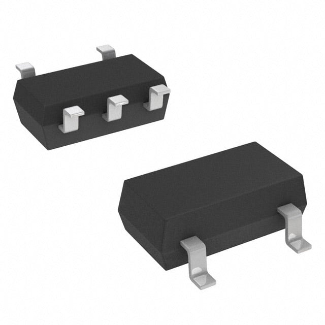
ICGOO在线商城 > 集成电路(IC) > 线性 - 放大器 - 仪表,运算放大器,缓冲器放大器 > AD8541AKSZ-REEL7
- 型号: AD8541AKSZ-REEL7
- 制造商: Analog
- 库位|库存: xxxx|xxxx
- 要求:
| 数量阶梯 | 香港交货 | 国内含税 |
| +xxxx | $xxxx | ¥xxxx |
查看当月历史价格
查看今年历史价格
AD8541AKSZ-REEL7产品简介:
ICGOO电子元器件商城为您提供AD8541AKSZ-REEL7由Analog设计生产,在icgoo商城现货销售,并且可以通过原厂、代理商等渠道进行代购。 AD8541AKSZ-REEL7价格参考¥2.25-¥2.25。AnalogAD8541AKSZ-REEL7封装/规格:线性 - 放大器 - 仪表,运算放大器,缓冲器放大器, General Purpose Amplifier 1 Circuit Rail-to-Rail SC-70-5。您可以下载AD8541AKSZ-REEL7参考资料、Datasheet数据手册功能说明书,资料中有AD8541AKSZ-REEL7 详细功能的应用电路图电压和使用方法及教程。
AD8541AKSZ-REEL7是Analog Devices Inc.生产的一款单通道、低功耗、精密CMOS运算放大器,属于线性放大器类别,适用于对精度和功耗有较高要求的应用场景。

该器件具有低失调电压、低输入偏置电流和宽电源电压范围(2.7V至5.5V),适合电池供电设备,广泛应用于便携式医疗设备,如血糖仪、心率监测仪等。其高输入阻抗和低噪声特性也使其适用于传感器信号调理,例如在工业自动化中处理温度、压力或应变传感器的微弱信号。

此外,AD8541AKSZ-REEL7具备良好的稳定性和输出驱动能力,可用于数据采集系统中的缓冲器或增益级,提升模拟信号链的精度与可靠性。在消费类电子产品中,如智能穿戴设备和无线传感器节点,因其小封装(SC70-5)和低静态电流,有助于节省空间并延长电池寿命。

该器件还适用于有源滤波、电压跟随及ADC驱动电路,在通信和音频前端电路中也有应用潜力。总体而言,AD8541AKSZ-REEL7凭借其精密性能和低功耗特点,广泛服务于工业、医疗、消费电子等领域中的模拟信号放大与处理需求。
| 参数 | 数值 |
| -3db带宽 | - |
| 产品目录 | 集成电路 (IC)半导体 |
| 描述 | IC OPAMP GP 1MHZ RRO SC70-5精密放大器 Gen-Purp CMOS SGL RR |
| 产品分类 | Linear - Amplifiers - Instrumentation, OP Amps, Buffer Amps集成电路 - IC |
| 品牌 | Analog Devices |
| 产品手册 | |
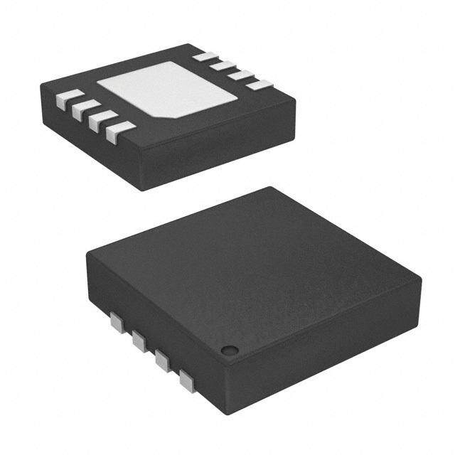
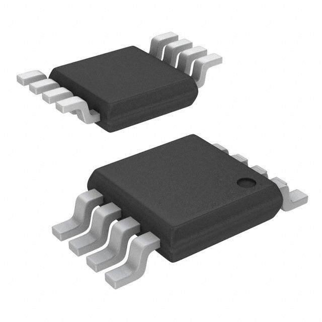
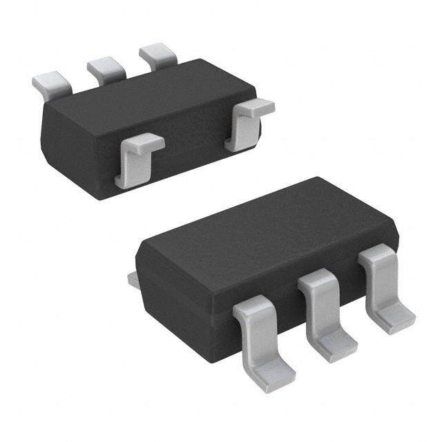
| 产品图片 |
|
| rohs | 符合RoHS无铅 / 符合限制有害物质指令(RoHS)规范要求 |
| 产品系列 | 放大器 IC,精密放大器,Analog Devices AD8541AKSZ-REEL7- |
| 数据手册 | |
| 产品型号 | AD8541AKSZ-REEL7 |
| 产品培训模块 | http://www.digikey.cn/PTM/IndividualPTM.page?site=cn&lang=zhs&ptm=30008http://www.digikey.cn/PTM/IndividualPTM.page?site=cn&lang=zhs&ptm=26202 |
| 产品目录页面 | |
| 产品种类 | 精密放大器 |
| 供应商器件封装 | SC-70-5 |
| 共模抑制比—最小值 | 48 dB |
| 关闭 | No |
| 其它名称 | AD8541AKSZ-REEL7DKR |
| 包装 | Digi-Reel® |
| 压摆率 | 0.92 V/µs |
| 可用增益调整 | 114 dB |
| 商标 | Analog Devices |
| 增益带宽生成 | 1 MHz |
| 增益带宽积 | 1MHz |
| 安装类型 | 表面贴装 |
| 安装风格 | SMD/SMT |
| 封装 | Reel |
| 封装/外壳 | 6-TSSOP(5 引线),SC-88A,SOT-353 |
| 封装/箱体 | SC70-5 |
| 工作温度 | -40°C ~ 125°C |
| 工作电源电压 | 2.7 V to 5.5 V |
| 工厂包装数量 | 3000 |
| 放大器类型 | 通用 |
| 最大工作温度 | + 125 C |
| 最小工作温度 | - 40 C |
| 标准包装 | 1 |
| 电压-电源,单/双 (±) | 2.7 V ~ 5.5 V |
| 电压-输入失调 | 1mV |
| 电压增益dB | 92.04 dB |
| 电流-电源 | 45µA |
| 电流-输入偏置 | 4pA |
| 电流-输出/通道 | 30mA |
| 电源电压-最大 | 5.5 V |
| 电源电压-最小 | 2.7 V |
| 电源电流 | 45 uA |
| 电源类型 | Single |
| 电路数 | 1 |
| 系列 | AD8541 |
| 视频文件 | http://www.digikey.cn/classic/video.aspx?PlayerID=1364138032001&width=640&height=505&videoID=2245193153001 |
| 设计资源 | |
| 转换速度 | 0.92 V/us |
| 输入偏压电流—最大 | 1000 pA |
| 输入电压范围—最大 | 5 V |
| 输入补偿电压 | 1 mV |
| 输出电流 | 30 mA |
| 输出类型 | Rail to Rail Input/Output |
| 通道数量 | 1 Channel |




- 商务部:美国ITC正式对集成电路等产品启动337调查
- 曝三星4nm工艺存在良率问题 高通将骁龙8 Gen1或转产台积电
- 太阳诱电将投资9.5亿元在常州建新厂生产MLCC 预计2023年完工
- 英特尔发布欧洲新工厂建设计划 深化IDM 2.0 战略
- 台积电先进制程称霸业界 有大客户加持明年业绩稳了
- 达到5530亿美元!SIA预计今年全球半导体销售额将创下新高
- 英特尔拟将自动驾驶子公司Mobileye上市 估值或超500亿美元
- 三星加码芯片和SET,合并消费电子和移动部门,撤换高东真等 CEO
- 三星电子宣布重大人事变动 还合并消费电子和移动部门
- 海关总署:前11个月进口集成电路产品价值2.52万亿元 增长14.8%


PDF Datasheet 数据手册内容提取
CMOS Rail-to-Rail General-Purpose Amplifiers AD8541/AD8542/AD8544 FEATURES PIN CONFIGURATIONS Single-supply operation: 2.7 V to 5.5 V Low supply current: 45 μA/amplifier AD8541 Wide bandwidth: 1 MHz OUT A 1 5 V+ No phase reversal V– 2 LUonwit yin gpauint csutarrbelnet s: 4 pA +IN A 3 4 –IN A 00935-001 Rail-to-rail input and output Figure 1. 5-Lead SC70 and 5-Lead SOT-23 Qualified for automotive applications (KS and RJ Suffixes) APPLICATIONS ASIC input or output amplifiers NC 1 AD8541 8 NC Sensor interfaces –IN A 2 7 V+ Piezoelectric transducer amplifiers +IN A 3 6 OUTA Medical instrumentation MAuodbiiole o cuotmpumtsu nications V– N4C = NO CONNEC5T NC 00935-002 Portable systems Figure 2. 8-Lead SOIC (R Suffix) GENERAL DESCRIPTION The AD8541/AD8542/AD8544 are single, dual, and quad rail- OUT A 1 AD8542 8 V+ to-rail input and output, single-supply amplifiers featuring very –IN A 2 7 OUT B low supply current and 1 MHz bandwidth. All are guaranteed to operate from a 2.7 V single supply as well as a 5 V supply. These +IN A 3 6 –IN B pofa r4t5s μpAro vpiedre a 1m MplHifize rb. a ndwidth at a low current consumption V– 4 5 +IN B 00935-003 Very low input bias currents enable the AD8541/AD8542/AD8544 Figure 3. 8-Lead SOIC, 8-Lead MSOP, and 8-Lead TSSOP (R, RM, and RU Suffixes) to be used for integrators, photodiode amplifiers, piezoelectric sensors, and other applications with high source impedance. The supply current is only 45 μA per amplifier, ideal for battery operation. OUT A 1 14 OUTD Rail-to-rail inputs and outputs are useful to designers buffering –IN A 2 13 –IN D ASICs in single-supply systems. The AD8541/AD8542/AD8544 +IN A 3 12 +IN D are optimized to maintain high gains at lower supply voltages, AD8544 making them useful for active filters and gain stages. V+ 4 11 V– The AD8541/AD8542/AD8544 are specified over the extended +IN B 5 10 +IN C industrial temperature range (–40°C to +125°C). The AD8541 –IN B 6 9 –IN C ipsa acvkaaigleasb. lTe hine A5-Dle8a5d4 2S OisT a-v2a3il,a 5b-lele iand 8 S-lCea7d0 ,S aOnIdC 8, 8-l-eleaadd S MOSICO P, OUT B 7 8 OUTC 00935-004 and 8-lead TSSOP surface-mount packages. The AD8544 is Figure 4. 14-Lead SOIC and 14-Lead TSSOP available in 14-lead narrow SOIC and 14-lead TSSOP surface- (R and RU Suffixes) mount packages. All MSOP, SC70, and SOT versions are available in tape and reel only. See the Ordering Guide for automotive models. Rev. G Information furnished by Analog Devices is believed to be accurate and reliable. However, no responsibility is assumed by Analog Devices for its use, nor for any infringements of patents or other One Technology Way, P.O. Box 9106, Norwood, MA 02062-9106, U.S.A. rights of third parties that may result from its use. Specifications subject to change without notice. No license is granted by implication or otherwise under any patent or patent rights of Analog Devices. Tel: 781.329.4700 www.analog.com Trademarks and registered trademarks are the property of their respective owners. Fax: 781.461.3113 ©2008–2011 Analog Devices, Inc. All rights reserved.
AD8541/AD8542/AD8544 TABLE OF CONTENTS Features..............................................................................................1 Theory of Operation......................................................................13 Applications.......................................................................................1 Notes on the AD854x Amplifiers.............................................13 General Description.........................................................................1 Applications.....................................................................................14 Pin Configurations...........................................................................1 Notch Filter.................................................................................14 Revision History...............................................................................2 Comparator Function................................................................14 Specifications.....................................................................................3 Photodiode Application............................................................15 Electrical Characteristics.............................................................3 Outline Dimensions.......................................................................16 Absolute Maximum Ratings............................................................6 Ordering Guide..........................................................................19 Thermal Resistance......................................................................6 Automotive Products.................................................................19 ESD Caution..................................................................................6 Typical Performance Characteristics.............................................7 REVISION HISTORY 6/11—Rev. F to Rev. G 1/07—Rev. D to Rev. E Changes to Features Section and General Description Updated Format..................................................................Universal Section................................................................................................1 Changes to Photodiode Application Section..............................14 Changes to Table 5............................................................................6 Changes to Ordering Guide..........................................................17 Updated Outline Dimensions.......................................................16 8/04—Rev. C to Rev. D Changes to Ordering Guide..........................................................19 Changes to Ordering Guide.............................................................5 Added Automotive Products Section..........................................19 Changes to Figure 3........................................................................10 1/08—Rev. E to Rev. F Updated Outline Dimensions.......................................................12 Inserted Figure 21; Renumbered Sequentially..............................9 1/03—Rev. B to Rev. C Changes to Figure 22 Caption.........................................................9 Updated Format..................................................................Universal Changes to Notch Filter Section, Figure 35, Figure 36, and Changes to General Description.....................................................1 Figure 37..........................................................................................13 Changes to Ordering Guide.............................................................5 Updated Outline Dimensions.......................................................16 Changes to Outline Dimensions..................................................12 Rev. G | Page 2 of 20
AD8541/AD8542/AD8544 SPECIFICATIONS ELECTRICAL CHARACTERISTICS V = 2.7 V, V = 1.35 V, T = 25°C, unless otherwise noted. S CM A Table 1. Parameter Symbol Conditions Min Typ Max Unit INPUT CHARACTERISTICS Offset Voltage V 1 6 mV OS −40°C ≤ T ≤ +125°C 7 mV A Input Bias Current I 4 60 pA B −40°C ≤ T ≤ +85°C 100 pA A −40°C ≤ T ≤ +125°C 1000 pA A Input Offset Current I 0.1 30 pA OS −40°C ≤ T ≤ +85°C 50 pA A −40°C ≤ T ≤ +125°C 500 pA A Input Voltage Range 0 2.7 V Common-Mode Rejection Ratio CMRR V = 0 V to 2.7 V 40 45 dB CM −40°C ≤ T ≤ +125°C 38 dB A Large Signal Voltage Gain A R = 100 kΩ, V = 0.5 V to 2.2 V 100 500 V/mV VO L O −40°C ≤ T ≤ +85°C 50 V/mV A −40°C ≤ T ≤ +125°C 2 V/mV A Offset Voltage Drift ΔV /ΔT −40°C ≤ T ≤ +125°C 4 μV/°C OS A Bias Current Drift ΔI/ΔT −40°C ≤ T ≤ +85°C 100 fA/°C B A −40°C ≤ T ≤ +125°C 2000 fA/°C A Offset Current Drift ΔI /ΔT −40°C ≤ T ≤ +125°C 25 fA/°C OS A OUTPUT CHARACTERISTICS Output Voltage High V I = 1 mA 2.575 2.65 V OH L −40°C ≤ T ≤ +125°C 2.550 V A Output Voltage Low V I = 1 mA 35 100 mV OL L −40°C ≤ T ≤ +125°C 125 mV A Output Current I V = V − 1 V 15 mA OUT OUT S I ±20 mA SC Closed-Loop Output Impedance Z f = 200 kHz, A = 1 50 Ω OUT V POWER SUPPLY Power Supply Rejection Ratio PSRR V = 2.5 V to 6 V 65 76 dB S −40°C ≤ T ≤ +125°C 60 dB A Supply Current/Amplifier I V = 0 V 38 55 μA SY O −40°C ≤ T ≤ +125°C 75 μA A DYNAMIC PERFORMANCE Slew Rate SR R = 100 kΩ 0.4 0.75 V/μs L Settling Time t To 0.1% (1 V step) 5 μs S Gain Bandwidth Product GBP 980 kHz Phase Margin 63 Degrees Φ M NOISE PERFORMANCE Voltage Noise Density e f = 1 kHz 40 nV/√Hz n e f = 10 kHz 38 nV/√Hz n Current Noise Density i <0.1 pA/√Hz n Rev. G | Page 3 of 20
AD8541/AD8542/AD8544 V = 3.0 V, V = 1.5 V, T = 25°C, unless otherwise noted. S CM A Table 2. Parameter Symbol Conditions Min Typ Max Unit INPUT CHARACTERISTICS Offset Voltage V 1 6 mV OS −40°C ≤ T ≤ +125°C 7 mV A Input Bias Current I 4 60 pA B −40°C ≤ T ≤ +85°C 100 pA A −40°C ≤ T ≤ +125°C 1000 pA A Input Offset Current I 0.1 30 pA OS −40°C ≤ T ≤ +85°C 50 pA A −40°C ≤ T ≤ +125°C 500 pA A Input Voltage Range 0 3 V Common-Mode Rejection Ratio CMRR V = 0 V to 3 V 40 45 dB CM −40°C ≤ T ≤ +125°C 38 dB A Large Signal Voltage Gain A R = 100 kΩ, V = 0.5 V to 2.2 V 100 500 V/mV VO L O −40°C ≤ T ≤ +85°C 50 V/mV A −40°C ≤ T ≤ +125°C 2 V/mV A Offset Voltage Drift ΔV /ΔT −40°C ≤ T ≤ +125°C 4 μV/°C OS A Bias Current Drift ΔI/ΔT −40°C ≤ T ≤ +85°C 100 fA/°C B A −40°C ≤ T ≤ +125°C 2000 fA/°C A Offset Current Drift ΔI /ΔT −40°C ≤ T ≤ +125°C 25 fA/°C OS A OUTPUT CHARACTERISTICS Output Voltage High V I = 1 mA 2.875 2.955 V OH L −40°C ≤ T ≤ +125°C 2.850 V A Output Voltage Low V I = 1 mA 32 100 mV OL L −40°C ≤ T ≤ +125°C 125 mV A Output Current I V = V − 1 V 18 mA OUT OUT S I ±25 mA SC Closed-Loop Output Impedance Z f = 200 kHz, A = 1 50 Ω OUT V POWER SUPPLY Power Supply Rejection Ratio PSRR V = 2.5 V to 6 V 65 76 dB S −40°C ≤ T ≤ +125°C 60 dB A Supply Current/Amplifier I V = 0 V 40 60 μA SY O −40°C ≤ T ≤ +125°C 75 μA A DYNAMIC PERFORMANCE Slew Rate SR R = 100 kΩ 0.4 0.8 V/μs L Settling Time t To 0.01% (1 V step) 5 μs S Gain Bandwidth Product GBP 980 kHz Phase Margin Φ 64 Degrees M NOISE PERFORMANCE Voltage Noise Density e f = 1 kHz 42 nV/√Hz n e f = 10 kHz 38 nV/√Hz n Current Noise Density i <0.1 pA/√Hz n Rev. G | Page 4 of 20
AD8541/AD8542/AD8544 V = 5.0 V, V = 2.5 V, T = 25°C, unless otherwise noted. S CM A Table 3. Parameter Symbol Conditions Min Typ Max Unit INPUT CHARACTERISTICS Offset Voltage V 1 6 mV OS −40°C ≤ T ≤ +125°C 7 mV A Input Bias Current I 4 60 pA B −40°C ≤ T ≤ +85°C 100 pA A −40°C ≤ T ≤ +125°C 1000 pA A Input Offset Current I 0.1 30 pA OS −40°C ≤ T ≤ +85°C 50 pA A −40°C ≤ T ≤ +125°C 500 pA A Input Voltage Range 0 5 V Common-Mode Rejection Ratio CMRR V = 0 V to 5 V 40 48 dB CM −40°C ≤ T ≤ +125°C 38 dB A Large Signal Voltage Gain A R = 100 kΩ, V = 0.5 V to 2.2 V 20 40 V/mV VO L O −40°C ≤ T ≤ +85°C 10 V/mV A −40°C ≤ T ≤ +125°C 2 V/mV A Offset Voltage Drift ΔV /ΔT −40°C ≤ T ≤ +125°C 4 μV/°C OS A Bias Current Drift ΔI/ΔT −40°C ≤ T ≤ +85°C 100 fA/°C B A −40°C ≤ T ≤ +125°C 2000 fA/°C A Offset Current Drift ΔI /ΔT −40°C ≤ T ≤ +125°C 25 fA/°C OS A OUTPUT CHARACTERISTICS Output Voltage High V I = 1 mA 4.9 4.965 V OH L −40°C ≤ T ≤ +125°C 4.875 V A Output Voltage Low V I = 1 mA 25 100 mV OL L −40°C ≤ T ≤ +125°C 125 mV A Output Current I V = V − 1 V 30 mA OUT OUT S I ±60 mA SC Closed-Loop Output Impedance Z f = 200 kHz, A = 1 45 Ω OUT V POWER SUPPLY Power Supply Rejection Ratio PSRR V = 2.5 V to 6 V 65 76 dB S −40°C ≤ T ≤ +125°C 60 dB A Supply Current/Amplifier I V = 0 V 45 65 μA SY O −40°C ≤ T ≤ +125°C 85 μA A DYNAMIC PERFORMANCE Slew Rate SR R = 100 kΩ, C = 200 pF 0.45 0.92 V/μs L L Full Power Bandwidth BW 1% distortion 70 kHz P Settling Time t To 0.1% (1 V step) 6 μs S Gain Bandwidth Product GBP 1000 kHz Phase Margin Φ 67 Degrees M NOISE PERFORMANCE Voltage Noise Density e f = 1 kHz 42 nV/√Hz n e f = 10 kHz 38 nV/√Hz n Current Noise Density i <0.1 pA/√Hz n Rev. G | Page 5 of 20
AD8541/AD8542/AD8544 ABSOLUTE MAXIMUM RATINGS THERMAL RESISTANCE Table 4. θ is specified for the worst-case conditions, that is, a device Parameter Rating JA soldered in a circuit board for surface-mount packages and Supply Voltage (V) 6 V S measured using a standard 4-layer board, unless otherwise Input Voltage GND to V S specified. Differential Input Voltage1 ±6 V Storage Temperature Range −65°C to +150°C Table 5. Operating Temperature Range −40°C to +125°C Package Type θ θ Unit JA JC Junction Temperature Range −65°C to +150°C 5-Lead SC70 (KS) 376 126 °C/W Lead Temperature (Soldering, 60 sec) 300°C 5-Lead SOT-23 (RJ) 190 92 °C/W 8-Lead SOIC (R) 120 45 °C/W 1 For supplies less than 6 V, the differential input voltage is equal to ±VS. 8-Lead MSOP (RM) 142 45 °C/W Stresses above those listed under Absolute Maximum Ratings 8-Lead TSSOP (RU) 240 43 °C/W may cause permanent damage to the device. This is a stress 14-Lead SOIC (R) 115 36 °C/W rating only; functional operation of the device at these or any 14-Lead TSSOP (RU) 112 35 °C/W other conditions above those indicated in the operational section of this specification is not implied. Exposure to absolute maximum rating conditions for extended periods may affect ESD CAUTION device reliability. Rev. G | Page 6 of 20
AD8541/AD8542/AD8544 TYPICAL PERFORMANCE CHARACTERISTICS 180 400 VS=5V VS = 2.7V AND 5V 160 VCM=2.5V 350 VCM = VS/2 TA=25°C 140 S A)300 R p LIFIE120 ENT (250 MP100 RR OF A 80 S CU200 ER BIA150 MB 60 UT U P N N100 40 I 20 50 0–4.5 –3.5 –2.5INP–U1T.5 OFF–S0.E5TVO0.L5TAGE1.5(mV)2.5 3.5 4.5 00935-005 0–40 –20 0 20TEMP4E0RATU6R0E (°C8)0 100 120 140 00935-008 Figure 5. Input Offset Voltage Distribution Figure 8. Input Bias Current vs. Temperature 1.0 7 0.5 VVSC M= =2 .V7SV/ 2AND 5V 6 VVSC M= =2 .V7SV/ 2AND 5V mV) 0 pA) 5 E (–0.5 T ( G N LTA–1.0 RRE 4 O U T V–1.5 T C 3 E E S S FF–2.0 FF 2 O O T –2.5 T U U P P 1 IN–3.0 IN 0 –3.5 –4.0–55 –35 –15 5 TEM25PERA45TURE6 5(°C) 85 105 125 145 00935-006 –1–55 –35 –15 5 TE2M5PERA45TURE6 5(°C) 85 105 125 145 00935-009 Figure 6. Input Offset Voltage vs. Temperature Figure 9. Input Offset Current vs. Temperature 9 160 8 VVSC M= =2 .V7VS/ 2AND 5V 140 VTAS == 225.7°VC pA)7 N (dB)120 RRENT (56 EJECTIO10800 –PSRR U R AS C4 PLY 60 +PSRR T BI3 SUP 40 INPU2 WER 20 O 0 P 1 –20 0–0.5 0.5 COM1.M5ON-MO2D.E5 VOLTA3G.5E (V) 4.5 5.5 00935-007 –40100 1k F1R0EkQUENCY1 (0H0zk) 1M 10M 00935-010 Figure 7. Input Bias Current vs. Common-Mode Voltage Figure 10. Power Supply Rejection vs. Frequency Rev. G | Page 7 of 20
AD8541/AD8542/AD8544 10k 60 VS = 2.7V VS = 2.7V TA = 25°C RL = 10kΩ 1k %)50 TA = 25°C E (mV)100 HOOT (40 +OS OLTAG 10 SOURCE SINK OVERS30 –OS V L UT NA P G OUT 1 L SI20 ∆ AL M 0.1 S10 0.010.001 0.01 LOA0D.1 CURRENT 1(mA) 10 100 00935-011 010 10C0APACITANCE (pF)1k 10k 00935-014 Figure 11. Output Voltage to Supply Rail vs. Load Current Figure 14. Small Signal Overshoot vs. Load Capacitance 3.0 60 VS = 2.7V VS = 2.7V VIN = 2.5V p-p RL = 2kΩ 2.5 RTAL == 225k°ΩC T (%)50 TA = 25°C p) O V p-2.0 SHO40 NG ( VER +OS WI1.5 O30 S L TPUT 1.0 SIGNA20 –OS OU LL A M 0.5 S10 01k 10k FREQU1E00NkCY (Hz) 1M 10M 00935-012 010 10C0APACITANCE (pF)1k 10k 00935-015 Figure 12. Closed-Loop Output Voltage Swing vs. Frequency Figure 15. Small Signal Overshoot vs. Load Capacitance 60 VS = 2.7V RL =∞ %)50 TA = 25°C VS = 2.7V HOOT (40 +OS RCALLV === 1310000kpΩF RS TA = 25°C E V O30 AL –OS GN 1.35V SI20 L L A M S10 010 10C0APACITANCE (pF)1k 10k 00935-013 50mV 10µs 00935-016 Figure 13. Small Signal Overshoot vs. Load Capacitance Figure 16. Small Signal Transient Response Rev. G | Page 8 of 20
AD8541/AD8542/AD8544 90 VS = 2.7V VS = 5V RL = 2kΩ 80 TA = 25°C ATAV == 215°C dB) 70 N ( O 60 TI C E 50 J E 1.35V E R 40 D MO 30 N- O 20 M M O 10 C 500mV 10µs 00935-017 –1001k 10k FREQU1E0N0kCY (Hz) 1M 10M 00935-020 Figure 17. Large Signal Transient Response Figure 20. Common-Mode Rejection vs. Frequency 5 VS = 2.7V VS=5V RL = NO LOAD 4 RL= NOLOAD TA = 25°C TA=25°C V) 3 m GAIN (dB)86420000 4915035 E SHIFT (Degrees) OFFSET VOLTAGE ( –1210 0 180 PHAS INPUT ––23 1k 10k FREQU1E0N0kCY (Hz) 1M 10M 00935-018 ––450 0.5 1.0 C1O.5MMO2N.0-MO2D.E5 VO3L.T0AGE3. 5(V) 4.0 4.5 5.000935-040 Figure 18. Open-Loop Gain and Phase vs. Frequency Figure 21. Input Offset Voltage vs. Common-Mode Voltage 160 10k VS = 5V VS = 5V O (dB)114200 TA = 25°C 1k TA = 25°C ATI V) R100 m TION 80 –PSRR AGE (100 EC LT SOURCE R SUPPLY REJ 642000 +PSRR ∆ OUTPUT VO 101 SINK E 0 W 0.1 O P–20 –40100 1k F1R0EkQUENCY1 (0H0zk) 1M 10M 00935-019 0.010.001 0.01 LOA0D.1 CURRENT 1(mA) 10 100 00935-021 Figure 19. Power Supply Rejection Ratio vs. Frequency Figure 22. Output Voltage to Supply Rail vs. Load Current Rev. G | Page 9 of 20
AD8541/AD8542/AD8544 5.0 60 VS = 5V VS = 5V 4.5 VIN = 4.9V p-p RL = 2kΩ 4.0 RTAL == 2N5O°C LOAD T (%)50 TA = 25°C V p-p)3.5 SHOO40 NG (3.0 VER +OS TPUT SWI22..50 SIGNAL O3200 –OS OU1.5 LL A 1.0 M S10 0.5 01k 10k FREQU1E0N0kCY (Hz) 1M 10M 00935-022 010 100CAPACITANCE (pF)1k 10k 00935-025 Figure 23. Closed-Loop Output Voltage Swing vs. Frequency, Figure 26. Small Signal Overshoot vs. Load Capacitance 5.0 60 VS = 5V VS = 5V 4.5 VIN = 4.9V p-p RL =∞ NG (V p-p)343...005 TRAL == 225k°ΩC VERSHOOT (%)4500 TA = 25°C +OS SWI2.5 L O30 PUT 2.0 GNA –OS OUT1.5 LL SI20 A 1.0 M S10 0.5 01k 10k FREQU1E0N0kCY (Hz) 1M 10M 00935-023 010 100CAPACITANCE (pF)1k 10k 00935-026 Figure 24. Closed-Loop Output Voltage Swing vs. Frequency Figure 27. Small Signal Overshoot vs. Load Capacitance 60 VS = 5V VS = 5V RL = 10kΩ RL = 100kΩ OT (%)50 TA = 25°C CATALV === 23150°0CpF HO40 S R +OS E V O30 2.5V L A –OS N G SI20 L L A M S10 010 10C0APACITANCE (pF)1k 10k 00935-024 50mV 10µs 00935-027 Figure 25. Small Signal Overshoot vs. Load Capacitance Figure 28. Small Signal Transient Response Rev. G | Page 10 of 20
AD8541/AD8542/AD8544 VS = 5V VS = 5V RL = 2kΩ RL = 10kΩ AV = 1 VIN AV = 1 TA = 25°C TA = 25°C VOUT 2.5V 2.5V 1V 10µs 00935-028 1V 20µs 00935-030 Figure 29. Large Signal Transient Response Figure 31. No Phase Reversal 60 VRSL == 5NVO LOAD TA = 25°C TA = 25°C A)50 µ R ( 80 E B)60 45 grees) MPLIFI40 GAIN (d4200 91035 HIFT (De RENT/A30 S R 0 180 ASE Y CU20 H L P P P SU10 1k 10k FREQU1E0N0kCY (Hz) 1M 10M 00935-029 00 1 S2UPPLY VO3LTAGE (V4) 5 6 00935-031 Figure 30. Open-Loop Gain and Phase vs. Frequency Figure 32. Supply Current per Amplifier vs. Supply Voltage Rev. G | Page 11 of 20
AD8541/AD8542/AD8544 55 VS=5V MARKERSET@10kHz A)50 MARKERREADING:37.6nV/ Hz R (µ VS = 5V TA=25°C E45 FI LI AMP40 DIV RENT/35 VS = 2.7V 15nV/ R U C Y 30 L P P U S25 20–55 –35 –15 5 TE2M5PERA45TURE6 5(°C) 85 105 125 145 00935-032 0 5 FR1E0QUENCY(k1H5z) 20 25 00935-034 Figure 33. Supply Current per Amplifier vs. Temperature Figure 35. Voltage Noise 1000 900 VS=2.7VAND5V AV=1 800 TA=25°C 700 Ω) E ( 600 C AN 500 D E P 400 M I 300 200 100 01k 10k F10R0EkQUENCY(1HMz) 10M 100M00935-033 Figure 34. Closed-Loop Output Impedance vs. Frequency Rev. G | Page 12 of 20
AD8541/AD8542/AD8544 THEORY OF OPERATION NOTES ON THE AD854X AMPLIFIERS Higher Output Current The AD8541/AD8542/AD8544 amplifiers are improved At 5 V single supply, the short-circuit current is typically 60 μA. performance, general-purpose operational amplifiers. Even 1 V from the supply rail, the AD854x amplifiers can provide a Performance has been improved over previous amplifiers in 30 mA output current, sourcing, or sinking. several ways, including lower supply current for 1 MHz gain Sourcing and sinking are strong at lower voltages, with 15 mA bandwidth, higher output current, and better performance at available at 2.7 V and 18 mA at 3.0 V. For even higher output lower voltages. currents, see the AD8531/AD8532/AD8534 parts for output Lower Supply Current for 1 MHz Gain Bandwidth currents to 250 mA. Information on these parts is available from your Analog Devices, Inc. representative, and data sheets The AD854x series typically uses 45 μA of current per amplifier, are available at www.analog.com. which is much less than the 200 μA to 700 μA used in earlier generation parts with similar performance. This makes the Better Performance at Lower Voltages AD854x series a good choice for upgrading portable designs The AD854x family of parts was designed to provide better ac for longer battery life. Alternatively, additional functions and performance at 3.0 V and 2.7 V than previously available parts. performance can be added at the same current drain. Typical gain bandwidth product is close to 1 MHz at 2.7 V. Voltage gain at 2.7 V and 3.0 V is typically 500,000. Phase margin is typically over 60°C, making the part easy to use. Rev. G | Page 13 of 20
AD8541/AD8542/AD8544 APPLICATIONS NOTCH FILTER Figure 38 is an example of the AD8544 in a notch filter circuit. The frequency dependent negative resistance (FDNR) notch filter has The AD854x have very high open-loop gain (especially with a fewer critical matching requirements than the twin-T notch, where supply voltage below 4 V), which makes it useful for active filters of as the Q of the FDNR is directly proportional to a single resistor R1. all types. For example, Figure 36 illustrates the AD8542 in the Although matching component values is still important, it is also classic twin-T notch filter design. The twin-T notch is desired much easier and/or less expensive to accomplish in the FDNR for simplicity, low output impedance, and minimal use of op circuit. For example, the twin-T notch uses three capacitors amps. In fact, this notch filter can be designed with only one op with two unique values, whereas the FDNR circuit uses only amp if Q adjustment is not required. Simply remove U2 as two capacitors, which may be of the same value. U3 is simply a illustrated in Figure 37. However, a major drawback to this buffer that is added to lower the output impedance of the circuit. circuit topology is ensuring that all the Rs and Cs closely match. The components must closely match or notch frequency offset 1/4 AD8544 R1 9 and drift causes the circuit to no longer attenuate at the ideal Q ADJUST 8 notch frequency. To achieve desired performance, 1% or better 200Ω 10 U3 VOUT component tolerances or special component screens are usually VIN 1CµF1 required. One method to desensitize the circuit-to-component mismatch is to increase R2 with respect to R1, which lowers Q. 2.5VREF R 2.61kΩ A lower Q increases attenuation over a wider frequency range 3 4 1/4 AD8544 C2 but reduces attenuation at the peak notch frequency. 1/4 AD8544 1µF U1 1 6 2 7 11 U2 R 5 2.61kΩ 5.0V R R R 100kΩ 100kΩ 3 8 1/2 AD8542 1 2.61kΩ VIN 53.62µCF 2 U1 4 1 VOUT fL = = 2Rπ2 C L2C1 R2.61kΩ 13 1/4 A1D48544 2.5VREF R/2 2.5VREF 12 U4 NC C 50kΩC 1/2 ADV8IN542 R2.25kΩ 2.5VREF 00935-037 26.7nF 26.7nF 5 Figure 38. FDNR 60 Hz Notch Filter with Output Buffer f0 =2π1RC 7 U2 6 COMPARATOR FUNCTION 1 R1 f0 =4 1 –R1R +1 R2 2.5VR9E7F.5kΩ 00935-035 Aam cpo minp aa qrautaodr pfuacnkcatgioen. F iisg ua rceo 3m9 millounst raaptpesl i¼ca toifo tnh efo Ar Da 8s5p4a4re a so pa Figure 36. 60 Hz Twin-T Notch Filter, Q = 10 comparator in a standard overload detection application. Unlike many op amps, the AD854x family can double as comparators because this op amp family has a rail-to-rail differential input 5.0V range, rail-to-rail output, and a great speed vs. power ratio. R R 3 7 AD8541 R2 is used to introduce hysteresis. The AD854x, when used as VIN 2C 2 U1 4 6 VOUT coovmerploaardat roercso, vhearvye t5im μse .p ropagation delay at 5 V and 5 μs 2.5VREF R2 1MΩ R/2 R1 C C 00935-036 VIN 1kΩ VOUT Figure 37. 60 Hz Twin-T Notch Filter, Q = ∞ (Ideal) 1/4 AD8541 2.5VREF 2.5VDC 00935-038 Figure 39. AD854x Comparator Application—Overload Detector Rev. G | Page 14 of 20
AD8541/AD8542/AD8544 PHOTODIODE APPLICATION C 100pF The AD854x family has very high impedance with an input bias R current typically around 4 pA. This characteristic allows the 10MΩ AD854x op amps to be used in photodiode applications and V+ other applications that require high input impedance. Note that OR 2 7 the AD854x has significant voltage offset that can be removed 6 V 3 OUT by capacitive coupling or software calibration. D 4AD8541 Fapigpulircea 4ti0o nil.l uTshtrea fteees dab pahcko troedsiiostdoer oisr lcimurirteendt t mo 1e0as MurΩem toen atv oid 2.5VREF 2.5VREF 00935-039 excessive output offset. In addition, a resistor is not needed on Figure 40. High Input Impedance Application—Photodiode Amplifier the noninverting input to cancel bias current offset because the bias current-related output offset is not significant when compared to the voltage offset contribution. For best performance, follow the standard high impedance layout techniques, which include the following: • Shielding the circuit. • Cleaning the circuit board. • Putting a trace connected to the noninverting input around the inverting input. • Using separate analog and digital power supplies. Rev. G | Page 15 of 20
AD8541/AD8542/AD8544 OUTLINE DIMENSIONS 3.00 2.90 2.80 1.70 5 4 3.00 1.60 2.80 1.50 2.60 1 2 3 0.95BSC 1.90 BSC 1.30 1.15 0.90 1.45MAX 0.20MAX 0.95MIN 0.08MIN 0.55 0.15MAX 10° 0.45 0.05MIN 0.50MAX SPLEAATNIENG 5° B0S.6C0 0.35 0.35MIN 0° COMPLIANTTOJEDECSTANDARDSMO-178-AA 11-01-2010-A Figure 41. 5-Lead Small Outline Transistor Package [SOT-23] (RJ-5) Dimensions shown in millimeters 5.10 5.00 4.90 14 8 4.50 4.40 6.40 BSC 4.30 1 7 PIN 1 0.65 BSC 1.05 1.00 1M.2A0X 0.20 0.80 0.09 0.75 0.15 8° 0.60 0.05 0.30 SPLEAATNIENG 0° 0.45 COPLANARITY 0.19 0.10 COMPLIANT TO JEDEC STANDARDS MO-153-AB-1 061908-A Figure 42. 14-Lead Thin Shrink Small Outline Package [TSSOP] (RU-14) Dimensions shown in millimeters Rev. G | Page 16 of 20
AD8541/AD8542/AD8544 2.20 2.00 1.80 1.35 5 4 2.40 1.25 2.10 1.15 1 2 3 1.80 0.65BSC 1.00 1.10 0.40 0.90 0.80 0.10 0.70 0.46 0.10MAX 0.30 SPELAATNIENG 00..2028 0.36 COPLANARITY 0.15 0.26 0.10 COMPLIANTTOJEDECSTANDARDSMO-203-AA 072809-A Figure 43. 5-Lead Thin Shrink Small Outline Transistor Package [SC70] (KS-5) Dimensions shown in millimeters 8.75 (0.3445) 8.55 (0.3366) 4.00 (0.1575) 14 8 6.20 (0.2441) 3.80 (0.1496) 1 7 5.80 (0.2283) 1.27 (0.0500) 0.50 (0.0197) BSC 45° 1.75 (0.0689) 0.25 (0.0098) 0.25 (0.0098) 1.35 (0.0531) 8° 0.10 (0.0039) 0° COPLANARITY SEATING 0.10 0.51 (0.0201) PLANE 0.25 (0.0098) 1.27 (0.0500) 0.31 (0.0122) 0.17 (0.0067) 0.40 (0.0157) COMPLIANTTO JEDEC STANDARDS MS-012-AB C(RINOEFNPETARRREOENNLCLTEIHN EOGSN EDLSIYM)AEANNRDSEI AORRNOESU NANORDEET DAIN-PO MPFRIFLO LMPIIMRLELIATIMTEEER TFSEO; RIRN ECUQHSU EDI VIINMA LEDENENSSTIIOGSN NFS.OR 060606-A Figure 44. 14-Lead Standard Small Outline Package [SOIC_N] Narrow Body (R-14) Dimensions shown in millimeters and (inches) Rev. G | Page 17 of 20
AD8541/AD8542/AD8544 3.20 3.10 3.00 3.00 2.80 2.90 8 5 5.15 8 5 3.20 4.90 4.50 3.00 4.65 4.40 6.40 BSC 2.80 1 4 4.30 PIN1 1 4 IDENTIFIER 0.65BSC PIN 1 0.65 BSC 0.95 15°MAX 0.15 00..8755 1.10MAX 0.05 1M.A20X 8° CO00P..10L550A.1N0ARICTOYMPLIANT00..T4205OJEDECSTA60°°NDARDS00M..20O39-187-AA 000...854050 10-07-2009-B COPL0A.1N0ACROITMYPLI00A..31N09T TOSP ELJAAENTDIEENCG ST00A..20N09DARD0S° MO-153-AA 000...764505 Figure 45. 8-Lead Mini Small Outline Package [MSOP] Figure 46. 8-Lead Thin Shrink Small Outline Package [TSSOP] (RM-8) (RU-8) Dimensions shown in millimeters Dimensions shown in millimeters 5.00(0.1968) 4.80(0.1890) 8 5 4.00(0.1574) 6.20(0.2441) 3.80(0.1497) 1 4 5.80(0.2284) 1.27(0.0500) 0.50(0.0196) BSC 1.75(0.0688) 0.25(0.0099) 45° 0.25(0.0098) 1.35(0.0532) 8° 0.10(0.0040) 0° COPLANARITY 0.51(0.0201) 0.10 SEATING 0.31(0.0122) 0.25(0.0098) 10..2470((00..00510507)) PLANE 0.17(0.0067) COMPLIANTTOJEDECSTANDARDSMS-012-AA C(RINOEFNPEATRRREOENNLCLTEIHNEOGSNDELISYM)AEANNRDSEIAORRNOESUNANORDEETDAIN-POMPFRIFLOLMPIMIRLELIATIMTEEERTFSEO;RIRNECUQHSUEDIVIINMAELDENENSSTIIOGSNNFS.OR 012407-A Figure 47. 8-Lead Standard Small Outline Package [SOIC_N] Narrow Body (R-8) Dimensions shown in millimeters and (inches) Rev. G | Page 18 of 20
AD8541/AD8542/AD8544 ORDERING GUIDE Model1, 2 Temperature Range Package Description Package Option Branding AD8541AKSZ-R2 –40°C to +125°C 5-Lead SC70 KS-5 A12 AD8541AKSZ-REEL7 –40°C to +125°C 5-Lead SC70 KS-5 A12 AD8541ARTZ-R2 –40°C to +125°C 5-Lead SOT-23 RJ-5 A4A AD8541ARTZ-REEL –40°C to +125°C 5-Lead SOT-23 RJ-5 A4A AD8541ARTZ-REEL7 –40°C to +125°C 5-Lead SOT-23 RJ-5 A4A AD8541ARZ –40°C to +125°C 8-Lead SOIC_N R-8 AD8541ARZ-REEL –40°C to +125°C 8-Lead SOIC_N R-8 AD8541ARZ-REEL7 –40°C to +125°C 8-Lead SOIC_N R-8 AD8542ARZ –40°C to +125°C 8-Lead SOIC_N R-8 AD8542ARZ-REEL –40°C to +125°C 8-Lead SOIC_N R-8 AD8542ARZ-REEL7 –40°C to +125°C 8-Lead SOIC_N R-8 AD8542ARM-REEL –40°C to +125°C 8-Lead MSOP RM-8 AVA AD8542ARMZ –40°C to +125°C 8-Lead MSOP RM-8 AVA AD8542ARMZ-REEL –40°C to +125°C 8-Lead MSOP RM-8 AVA AD8542ARU-REEL –40°C to +125°C 8-Lead TSSOP RU-8 AD8542ARUZ –40°C to +125°C 8-Lead TSSOP RU-8 AD8542ARUZ-REEL –40°C to +125°C 8-Lead TSSOP RU-8 AD8544ARZ –40°C to +125°C 14-Lead SOIC_N R-14 AD8544ARZ-REEL –40°C to +125°C 14-Lead SOIC_N R-14 AD8544ARZ-REEL7 –40°C to +125°C 14-Lead SOIC_N R-14 AD8544ARUZ –40°C to +125°C 14-Lead TSSOP RU-14 AD8544ARUZ-REEL –40°C to +125°C 14-Lead TSSOP RU-14 AD8544WARZ-RL –40°C to +125°C 14-Lead SOIC_N R-14 AD8544WARZ-R7 –40°C to +125°C 14-Lead SOIC_N R-14 1 Z = RoHS Compliant Part. 2 W = Qualified for Automotive Applications. AUTOMOTIVE PRODUCTS The AD8544W models are available with controlled manufacturing to support the quality and reliability requirements of automotive applications. Note that these automotive models may have specifications that differ from the commercial models; therefore, designers should review the Specifications section of this data sheet carefully. Only the automotive grade products shown are available for use in automotive applications. Contact your local Analog Devices account representative for specific product ordering information and to obtain the specific Automotive Reliability reports for these models. Rev. G | Page 19 of 20
AD8541/AD8542/AD8544 NOTES ©2008–2011 Analog Devices, Inc. All rights reserved. Trademarks and registered trademarks are the property of their respective owners. D00935-0-6/11(G) Rev. G | Page 20 of 20
Mouser Electronics Authorized Distributor Click to View Pricing, Inventory, Delivery & Lifecycle Information: A nalog Devices Inc.: AD8541AKSZ-R2 AD8541AKSZ-REEL7 AD8541ARTZ-R2 AD8541ARTZ-REEL7 AD8541ARZ AD8542ARMZ AD8542ARMZ-REEL AD8542ARUZ AD8542ARZ AD8542ARZ-REEL7 AD8544ARUZ AD8544ARZ AD8541ARTZ- REEL AD8541ARZ-REEL AD8541ARZ-REEL7 AD8542ARUZ-REEL AD8542ARZ-REEL AD8544ARUZ-REEL AD8544ARZ-REEL AD8544ARZ-REEL7 AD8544WARZ-R7 AD8544WARZ-RL

 Datasheet下载
