ICGOO在线商城 > 集成电路(IC) > 线性 - 放大器 - 仪表,运算放大器,缓冲器放大器 > AD8532ARZ-REEL7
 Datasheet下载
- 型号: AD8532ARZ-REEL7
- 制造商: Analog
- 库位|库存: xxxx|xxxx
- 要求:
| 数量阶梯 | 香港交货 | 国内含税 |
| +xxxx | $xxxx | ¥xxxx |
查看当月历史价格
查看今年历史价格
AD8532ARZ-REEL7产品简介:
ICGOO电子元器件商城为您提供AD8532ARZ-REEL7由Analog设计生产,在icgoo商城现货销售,并且可以通过原厂、代理商等渠道进行代购。 AD8532ARZ-REEL7价格参考。AnalogAD8532ARZ-REEL7封装/规格:线性 - 放大器 - 仪表,运算放大器,缓冲器放大器, General Purpose Amplifier 2 Circuit Rail-to-Rail 8-SOIC。您可以下载AD8532ARZ-REEL7参考资料、Datasheet数据手册功能说明书,资料中有AD8532ARZ-REEL7 详细功能的应用电路图电压和使用方法及教程。
AD8532ARZ-REEL7是Analog Devices Inc.生产的一款双通道、低功耗、精密运算放大器,属于线性放大器类别,适用于仪表放大、信号调理和缓冲放大等应用。该器件具有低失调电压、低输入偏置电流和宽电源电压范围(2.7V至12V),适合电池供电设备和对精度要求较高的系统。

典型应用场景包括:工业自动化中的传感器信号放大,如压力、温度和应变片信号的调理;便携式医疗设备,如心电图(ECG)监测仪和血糖仪,得益于其低功耗和高精度特性;消费类电子产品中的音频信号处理和ADC驱动;以及数据采集系统中的多通道信号缓冲与放大。

此外,AD8532ARZ-REEL7具备轨到轨输入输出特性,能够在单电源系统中有效处理接近地电平或电源电压的信号,提升动态范围。其单位增益稳定设计也使其适用于电压跟随器(缓冲器)电路。器件采用SOIC-8封装,易于集成,并通过了工业级温度范围(-40°C至+125°C)测试,确保在严苛环境下的可靠性。

综上,AD8532ARZ-REEL7广泛应用于需要高精度、低功耗和小尺寸的工业、医疗和消费类电子系统中,是信号链前端放大和缓冲的理想选择。
| 参数 | 数值 |
| -3db带宽 | - |
| 产品目录 | 集成电路 (IC)半导体 |
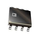
| 描述 | IC OPAMP GP 3MHZ RRO 8SOIC精密放大器 250mA Output Dual SGL-Supply |
| 产品分类 | Linear - Amplifiers - Instrumentation, OP Amps, Buffer Amps集成电路 - IC |
| 品牌 | Analog Devices |
| 产品手册 | |
| 产品图片 |
|
| rohs | 符合RoHS无铅 / 符合限制有害物质指令(RoHS)规范要求 |
| 产品系列 | 放大器 IC,精密放大器,Analog Devices AD8532ARZ-REEL7- |
| 数据手册 | |
| 产品型号 | AD8532ARZ-REEL7 |
| 产品培训模块 | http://www.digikey.cn/PTM/IndividualPTM.page?site=cn&lang=zhs&ptm=30008http://www.digikey.cn/PTM/IndividualPTM.page?site=cn&lang=zhs&ptm=26202 |
| 产品种类 | 精密放大器 |
| 供应商器件封装 | 8-SOIC N |
| 共模抑制比—最小值 | 47 dB |
| 关闭 | No |
| 其它名称 | AD8532ARZ-REEL7DKR |
| 包装 | Digi-Reel® |
| 压摆率 | 5 V/µs |
| 可用增益调整 | 70 dB |
| 商标 | Analog Devices |
| 增益带宽生成 | 3 MHz |
| 增益带宽积 | 3MHz |
| 安装类型 | 表面贴装 |
| 安装风格 | SMD/SMT |
| 封装 | Reel |
| 封装/外壳 | 8-SOIC(0.154",3.90mm 宽) |
| 封装/箱体 | SOIC-8 |
| 工作温度 | -40°C ~ 85°C |
| 工作电源电压 | 2.7 V to 6 V |
| 工厂包装数量 | 1000 |
| 放大器类型 | 通用 |
| 最大工作温度 | + 85 C |
| 最小工作温度 | - 40 C |
| 标准包装 | 1 |
| 电压-电源,单/双 (±) | 2.7 V ~ 6 V, ±1.35 V ~ 3 V |
| 电压-输入失调 | 25mV |
| 电压增益dB | 98.06 dB |
| 电流-电源 | 750µA |
| 电流-输入偏置 | 5pA |
| 电流-输出/通道 | 250mA |
| 电源电压-最大 | 6 V |
| 电源电压-最小 | 3 V |
| 电源电流 | 0.7 mA |
| 电源类型 | Single |
| 电路数 | 2 |
| 系列 | AD8532 |
| 视频文件 | http://www.digikey.cn/classic/video.aspx?PlayerID=1364138032001&width=640&height=505&videoID=2245193153001http://www.digikey.cn/classic/video.aspx?PlayerID=1364138032001&width=640&height=505&videoID=2245193159001 |
| 转换速度 | 5 V/us |
| 输入偏压电流—最大 | 60 pA |
| 输入电压范围—最大 | 5 V |
| 输入补偿电压 | 25 mV |
| 输出电流 | 250 mA |
| 输出类型 | Rail to Rail Input/Output |
| 通道数量 | 2 Channel |


- 商务部:美国ITC正式对集成电路等产品启动337调查
- 曝三星4nm工艺存在良率问题 高通将骁龙8 Gen1或转产台积电
- 太阳诱电将投资9.5亿元在常州建新厂生产MLCC 预计2023年完工
- 英特尔发布欧洲新工厂建设计划 深化IDM 2.0 战略
- 台积电先进制程称霸业界 有大客户加持明年业绩稳了
- 达到5530亿美元!SIA预计今年全球半导体销售额将创下新高
- 英特尔拟将自动驾驶子公司Mobileye上市 估值或超500亿美元
- 三星加码芯片和SET,合并消费电子和移动部门,撤换高东真等 CEO
- 三星电子宣布重大人事变动 还合并消费电子和移动部门
- 海关总署:前11个月进口集成电路产品价值2.52万亿元 增长14.8%


PDF Datasheet 数据手册内容提取
Low Cost, 250 mA Output, Single-Supply Amplifiers AD8531/AD8532/AD8534 FEATURES PIN CONFIGURATIONS Single-supply operation: 2.7 V to 6 V AD8531 High output current: ±250 mA OUT A 1 5 V+ Low supply current: 750 μA/amplifier V– 2 WSleidwe rbaaten:d 5w Vid/μths : 3 MHz +IN A 3 4 –IN A 01099-001 No phase reversal Figure 1. 5-Lead SC70 and 5-Lead SOT-23 Low input currents (KS and RJ Suffixes) Unity gain stable Rail-to-rail input and output NC 1 AD8531 8 NC APPLICATIONS –IN A 2 7 V+ +IN A 3 6 OUTA MLCuDlt dimrievedrias audio V– N4C = NO CONNECT5 NC 01099-002 ASIC input or output amplifiers Figure 2. 8-Lead SOIC Headphone drivers (R Suffix) GENERAL DESCRIPTION The AD8531, AD8532, and AD8534 are single, dual, and quad OUT A 1 8 V+ rail-to-rail input/output single-supply amplifiers featuring –IN A 2 7 OUT B 250 mA output drive current. This high output current makes +IN A 3 6 –IN B tlohaesdes .a AmCpl ipfieerrfso erxmcealnlecnet i fso vr edrryi vgionog de iwthietrh r3e sMistHivze bora ncdapwaicditthiv, e V– 4 AD8532 5 +IN B 01099-003 5 V/μs slew rate, and low distortion. All are guaranteed to operate Figure 3. 8-Lead SOIC, 8-Lead TSSOP, and 8-Lead MSOP from a 3 V single supply as well as a 5 V supply. (R, RU, and RM Suffixes) The very low input bias currents enable the AD853x to be used for integrators, diode amplification, and other applications requiring low input bias current. Supply current is only 750 μA per OUT A 1 14 OUTD –IN A 2 13 –IN D amplifier at 5 V, allowing low current applications to control high current loads. +IN A 3 12 +IN D V+ 4 AD8534 11 V– Applications include audio amplification for computers, sound +IN B 5 10 +IN C ports, sound cards, and set-top boxes. The AD853x family is –IN B 6 9 –IN C vsuercyh satsa bthleo,s aen fdo uitn ids cina pLaCbDle so. f driving heavy capacitive loads OUT B 7 8 OUTC01099-004 Figure 4. 14-Lead SOIC and 14-Lead TSSOP The ability to swing rail-to-rail at the inputs and outputs enables (R and RU Suffixes) designers to buffer CMOS DACs, ASICs, or other wide output swing devices in single-supply systems. The AD8531/AD8532/AD8534 are specified over the extended industrial temperature range (−40°C to +85°C). The AD8531 is available in 8-lead SOIC, 5-lead SC70, and 5-lead SOT-23 packages. The AD8532 is available in 8-lead SOIC, 8-lead MSOP, and 8-lead TSSOP surface-mount packages. The AD8534 is available in narrow 14-lead SOIC and 14-lead TSSOP surface-mount packages. Rev. F Information furnished by Analog Devices is believed to be accurate and reliable. However, no responsibility is assumed by Analog Devices for its use, nor for any infringements of patents or other One Technology Way, P.O. Box 9106, Norwood, MA 02062-9106, U.S.A. rights of third parties that may result from its use. Specifications subject to change without notice. No license is granted by implication or otherwise under any patent or patent rights of Analog Devices. Tel: 781.329.4700 www.analog.com Trademarks and registered trademarks are the property of their respective owners. Fax: 781.461.3113 ©1996–2008 Analog Devices, Inc. All rights reserved.
AD8531/AD8532/AD8534 TABLE OF CONTENTS Features..............................................................................................1 Calculating Power by Measuring Ambient and Case Applications.......................................................................................1 Temperature................................................................................12 General Description.........................................................................1 Calculating Power by Measuring Supply Current.................12 Pin Configurations...........................................................................1 Input Overvoltage Protection...................................................12 Revision History...............................................................................2 Output Phase Reversal...............................................................13 Specifications.....................................................................................3 Capacitive Load Drive...............................................................13 Electrical Characteristics.............................................................3 Applications Information..............................................................14 Absolute Maximum Ratings............................................................5 High Output Current, Buffered Reference/Regulator...........14 Thermal Resistance......................................................................5 Single-Supply, Balanced Line Driver.......................................14 ESD Caution..................................................................................5 Single-Supply Headphone Amplifier.......................................15 Typical Performance Characteristics.............................................6 Single-Supply, 2-Way Loudspeaker Crossover Network.......15 Theory of Operation......................................................................11 Direct Access Arrangement for Telephone Line Interface...16 Short-Circuit Protection............................................................11 Outline Dimensions.......................................................................17 Power Dissipation.......................................................................11 Ordering Guide..........................................................................20 Power Calculations for Varying or Unknown Loads.............12 REVISION HISTORY 1/08—Rev. E to Rev. F Changes to Layout............................................................................5 Changes to Figure 12 and Figure 13...............................................7 Changes to Figure 38......................................................................11 Changes to Input Overvoltage Protection Section.....................12 Changes to Figure 43......................................................................14 Updated Outline Dimensions.......................................................17 Changes to Ordering Guide..........................................................20 4/05—Rev. D to Rev. E Updated Format..................................................................Universal Changes to Pin Configurations.......................................................1 Changes to Table 4............................................................................5 Updated Outline Dimensions.......................................................18 Changes to Ordering Guide..........................................................19 10/02—Rev. C to Rev. D Deleted 8-Lead PDIP (N-8)..............................................Universal Deleted 14-Lead PDIP (N-14)..........................................Universal Edits to Figure 34...............................................................................9 Updated Outline Dimensions........................................................15 8/96—Revision 0: Initial Version Rev. F | Page 2 of 20
AD8531/AD8532/AD8534 SPECIFICATIONS ELECTRICAL CHARACTERISTICS V = 3.0 V, V = 1.5 V, T = 25°C, unless otherwise noted. S CM A Table 1. Parameter Symbol Conditions Min Typ Max Unit INPUT CHARACTERISTICS Offset Voltage V 25 mV OS −40°C ≤ T ≤ +85°C 30 mV A Input Bias Current I 5 50 pA B −40°C ≤ T ≤ +85°C 60 pA A Input Offset Current I 1 25 pA OS −40°C ≤ T ≤ +85°C 30 pA A Input Voltage Range 0 3 V Common-Mode Rejection Ratio CMRR V = 0 V to 3 V 38 45 dB CM Large Signal Voltage Gain A R = 2 kΩ, V = 0.5 V to 2.5 V 25 V/mV VO L O Offset Voltage Drift ΔV /ΔT 20 μV/°C OS Bias Current Drift ΔI/ΔT 50 fA/°C B Offset Current Drift ΔI /ΔT 20 fA/°C OS OUTPUT CHARACTERISTICS Output Voltage High V I = 10 mA 2.85 2.92 V OH L −40°C ≤ T ≤ +85°C 2.8 V A Output Voltage Low V I = 10 mA 60 100 mV OL L −40°C ≤ T ≤ +85°C 125 mV A Output Current I ±250 mA OUT Closed-Loop Output Impedance Z f = 1 MHz, A = 1 60 Ω OUT V POWER SUPPLY Power Supply Rejection Ratio PSRR V = 3 V to 6 V 45 55 dB S Supply Current/Amplifier I V = 0 V 0.70 1 mA SY O −40°C ≤ T ≤ +85°C 1.25 mA A DYNAMIC PERFORMANCE Slew Rate SR R = 2 kΩ 3.5 V/μs L Settling Time t To 0.01% 1.6 μs S Gain Bandwidth Product GBP 2.2 MHz Phase Margin фo 70 Degrees Channel Separation CS f = 1 kHz, R = 2 kΩ 65 dB L NOISE PERFORMANCE Voltage Noise Density e f = 1 kHz 45 nV/√Hz n f = 10 kHz 30 nV/√Hz Current Noise Density i f = 1 kHz 0.05 pA/√Hz n Rev. F | Page 3 of 20
AD8531/AD8532/AD8534 V = 5.0 V, V = 2.5 V, T = 25°C, unless otherwise noted. S CM A Table 2. Parameter Symbol Conditions Min Typ Max Unit INPUT CHARACTERISTICS Offset Voltage V 25 mV OS −40°C ≤ T ≤ +85°C 30 mV A Input Bias Current I 5 50 pA B −40°C ≤ T ≤ +85°C 60 pA A Input Offset Current I 1 25 pA OS −40°C ≤ T ≤ +85°C 30 pA A Input Voltage Range 0 5 V Common-Mode Rejection Ratio CMRR V = 0 V to 5 V 38 47 dB CM Large Signal Voltage Gain A R = 2 kΩ, V = 0.5 V to 4.5 V 15 80 V/mV VO L O Offset Voltage Drift ΔV /ΔT −40°C ≤ T ≤ +85°C 20 μV/°C OS A Bias Current Drift ΔI/ΔT 50 fA/°C B Offset Current Drift ΔI /ΔT 20 fA/°C OS OUTPUT CHARACTERISTICS Output Voltage High V I = 10 mA 4.9 4.94 V OH L −40°C ≤ T ≤ +85°C 4.85 V A Output Voltage Low V I = 10 mA 50 100 mV OL L −40°C ≤ T ≤ +85°C 125 mV A Output Current I ±250 mA OUT Closed-Loop Output Impedance Z f = 1 MHz, A = 1 40 Ω OUT V POWER SUPPLY Power Supply Rejection Ratio PSRR V = 3 V to 6 V 45 55 dB S Supply Current/Amplifier I V = 0 V 0.75 1.25 mA SY O −40°C ≤ T ≤ +85°C 1.75 mA A DYNAMIC PERFORMANCE Slew Rate SR R = 2 kΩ 5 V/μs L Full-Power Bandwidth BW 1% distortion 350 kHz p Settling Time t To 0.01% 1.4 μs S Gain Bandwidth Product GBP 3 MHz Phase Margin фo 70 Degrees Channel Separation CS f = 1 kHz, R = 2 kΩ 65 dB L NOISE PERFORMANCE Voltage Noise Density e f = 1 kHz 45 nV/√Hz n f = 10 kHz 30 nV/√Hz Current Noise Density i f = 1 kHz 0.05 pA/√Hz n Rev. F | Page 4 of 20
AD8531/AD8532/AD8534 ABSOLUTE MAXIMUM RATINGS Table 3. Parameter Rating 2.5 –VOL Supply Voltage (V) 7 V S Input Voltage GND to VS 2.0 +VOH Differential Input Voltage1 ±6 V Storage Temperature Range −65°C to +150°C 1.5 Operating Temperature Range −40°C to +85°C UT O Junction Temperature Range −65°C to +150°C V ± Lead Temperature (Soldering, 60 sec) 300°C 1.0 1 For supplies less than 6 V, the differential input voltage is equal to ±VS. 0.5 Stresses above those listed under Absolute Maximum Ratings mrataiyn gca ounsley p; tehrme faunnecntti odnaaml oagpee rtaot itohne odfe vthicee d. Tevhiicse i sa ta t shtersees so r 0 01099-005 0 20 40 60 80 100 120 140 160 180 200 any other conditions above those indicated in the operational RLOAD (Ω) sections of this specification is not implied. Exposure to absolute Figure 5. Output Voltage vs. Load, VS = ±2.5 V, maximum rating conditions for extended periods may affect RLOAD Is Connected to GND (0 V) device reliability. THERMAL RESISTANCE ESD CAUTION θ is specified for the worst-case conditions, that is, a device JA soldered in a circuit board for surface-mount packages. Table 4. Package Type θ θ Unit JA JC 5-Lead SC70 (KS) 376 126 °C/W 5-Lead SOT-23 (RJ) 230 146 °C/W 8-Lead SOIC (R) 158 43 °C/W 8-Lead MSOP (RM) 210 45 °C/W 8-Lead TSSOP (RU) 240 43 °C/W 14-Lead SOIC (R) 120 36 °C/W 14-Lead TSSOP (RU) 240 43 °C/W Rev. F | Page 5 of 20
AD8531/AD8532/AD8534 TYPICAL PERFORMANCE CHARACTERISTICS VS= 2.7V VS= 5V, 3V VCM= 1.35V 8 VCM = VS/2 500 TA= 25°C A) 7 ers) 400 T (p mplifi RREN 6 TY (A 300 S CU 5 NTI BIA 4 UA 200 UT Q P N 3 I 100 01099-006 2 01099-009 –12 –10 –8 –6 –4 –2 0 2 4 –35 –15 5 25 45 65 85 INPUT OFFSET VOLTAGE (mV) TEMPERATURE (°C) Figure 6. Input Offset Voltage Distribution Figure 9. Input Bias Current vs. Temperature VVSCM= =5 V2.5V TVAS == 2 55V°C 500 TA= 25°C 8 A) ers) 400 T (p 7 mplifi RREN 6 TY (A 300 S CU 5 NTI BIA 4 QUA 200 PUT 3 N I 2 100 01099-007 01099-010 –12 –10 –8 –6 –4 –2 0 2 4 0 1 2 3 4 5 INPUT OFFSET VOLTAGE (mV) COMMON-MODE VOLTAGE (V) Figure 7. Input Offset Voltage Distribution Figure 10. Input Bias Current vs. Common-Mode Voltage 6 VS= 5V VS= 5V, 3V –2 VCM= 2.5V 5 VCM = VS/2 mV) –3 pA) 4 E ( T ( G N TA –4 RE 3 OL UR OFFSET V ––56 OFFSET C 21 INPUT –7 INPUT 0 –8 –35 –15 5 25 45 65 85 01099-008 ––12 –35 –15 5 25 45 65 85 01099-011 TEMPERATURE (°C) TEMPERATURE (°C) Figure 8. Input Offset Voltage vs. Temperature Figure 11. Input Offset Current vs. Temperature Rev. F | Page 6 of 20
AD8531/AD8532/AD8534 1000 TVAS == 225.7°VC VRSL== 5NVO LOAD TA = 25°C AGE (mV) 100 SOURCE SINK B) 8600 45 Degrees) ΔOUTPUT VOLT 101 GAIN (d 42000 91103850 PHASE SHIFT ( 0.1 0.01 01099-012 01099-015 0.001 0.01 0.1 1 10 100 1k 10k 100k 1M 10M 100M LOAD CURRENT (mA) FREQUENCY (Hz) Figure 12. Output Voltage to Supply Rail vs. Load Current Figure 15. Open-Loop Gain and Phase Shift vs. Frequency 1000 VS= 5V 5 VS= 2.7V TA = 25°C TA = 25°C RL= 2kΩ 100 4 VIN= 2.5V p-p E (mV) V p-p) AG 10 SOURCE G ( 3 T N OL SINK WI V S UT 1 UT 2 P P T T U U O O Δ 0.1 1 0.001.001 0.01 0.1 1 10 100 01099-013 01k 10k 100k 1M 10M01099-016 LOAD CURRENT (mA) FREQUENCY (Hz) Figure 13. Output Voltage to Supply Rail vs. Load Current Figure 16. Closed-Loop Output Swing vs. Frequency 5 VS= 2.7V VS= 5V RL= NO LOAD TA = 25°C TA = 25°C RL= 2kΩ 4 VIN= 4.9V p-p 80 ees) p-p) gr V B) 60 45 De G ( 3 N (d 40 90 FT ( WIN GAI 20 135 SE SHI PUT S 2 0 180 PHA OUT 1 1k 10k F1R00EkQUENCY 1(HMz) 10M 100M 01099-014 01k 10k FREQU1E00NkCY (Hz) 1M 10M01099-017 Figure 14. Open-Loop Gain and Phase Shift vs. Frequency Figure 17. Closed-Loop Output Swing vs. Frequency Rev. F | Page 7 of 20
AD8531/AD8532/AD8534 200 1 VS= 5V VS= 5V 180 TA = 25°C TA = 25°C 160 Hz) √ A/ Ω) 140 TY (p E ( 120 NSI C E PEDAN 10800 OISE D 0.1 IM AV= 10 T N 60 AV= 1 REN 40 UR C 200 01099-018 0.01 01099-021 1k 10k 100k 1M 10M 100M 10 100 1k 10k 100k LOAD CURRENT (mA) FREQUENCY (Hz) Figure 18. Closed-Loop Output Impedance vs. Frequency Figure 21. Current Noise Density vs. Frequency 110 VS = 5V VS= 5V 10900 ATFARV E==Q 21U50°E0C0NCY = 1kHz B) 100 TA = 25°C d ON ( 90 TI C V E DI EJ 80 V/ R 100µ ODE 70 M N- O 10 MM 60 0% CO 01099-019 5400 01099-022 MARKER 41µV/√Hz 1k 10k 100k 1M 10M FREQUENCY (Hz) Figure 19. Voltage Noise Density vs. Frequency (1 kHz) Figure 22. Common-Mode Rejection vs. Frequency 140 VS = 5V VS= 2.7V 100 AV = 1000 120 TA = 25°C 90 TFAR E=Q 2U5°ECNCY = 10kHz B) 100 d N ( O 80 TI C V E 60 200µV/DI PPLY REJ 4200 PPSSSSRR+– U S R 0 10 WE 0% O –20 P 01099-020 ––4600 01099-023 MARKER 25.9µV/√Hz 100 1k 10k 100k 1M 10M FREQUENCY (Hz) Figure 20. Voltage Noise Density vs. Frequency (10 kHz) Figure 23. Power Supply Rejection vs. Frequency Rev. F | Page 8 of 20
AD8531/AD8532/AD8534 140 50 VS= 5V VS= 5V 120 TA = 25°C TA = 25°C RL= 600Ω B) 100 %) 40 TION (d 80 PSSR– HOOT ( EC 60 RS 30 UPPLY REJ 4200 PSSR+ GNAL OVE 20 –OS +OS ER S 0 LL SI W A PO –20 SM 10 ––4600 01099-024 0 01099-027 100 1k 10k 100k 1M 10M 10 100 1000 10000 FREQUENCY (Hz) CAPACITANCE (pF) Figure 24. Power Supply Rejection vs. Frequency Figure 27. Small Signal Overshoot vs. Load Capacitance 50 50 VS= 2.7V VS= 2.7V TA = 25°C TA = 25°C RL= 2kΩ RL= 600Ω %) 40 %) 40 T ( T ( O O O O H H RS 30 RS 30 E E V –OS V O O L L A A GN 20 GN 20 SI SI ALL +OS ALL –OS SM 10 SM 10 0 01099-025 0 +OS 01099-028 10 100 1000 10000 10 100 1000 10000 CAPACITANCE (pF) CAPACITANCE (pF) Figure 25. Small Signal Overshoot vs. Load Capacitance Figure 28. Small Signal Overshoot vs. Load Capacitance 60 0.90 VS= 5V TA = 25°C %) 50 RL= 2kΩ mA) 0.85 T ( R ( 0.80 O E VERSHO 40 –OS AMPLIFI 0.75 SIGNAL O 3200 +OS CURRENT/ 00..7605 VS= 5V ALL PLY 0.60 SM UP VS= 3V 10 S 0 01099-026 00..5550 01099-029 10 100 1000 10000 –40 –20 0 20 40 60 80 CAPACITANCE (pF) TEMPERATURE (°C) Figure 26. Small Signal Overshoot vs. Load Capacitance Figure 29. Supply Current per Amplifier vs. Temperature Rev. F | Page 9 of 20
AD8531/AD8532/AD8534 0.8 TA= 25°C VS =±2.5V mA) 0.7 10900 ARTAVL === 2215k°ΩC R ( 0.6 E FI LI 0.5 P M A T/ 0.4 N E R UR 0.3 C Y PL 0.2 10 UP 0% S 0.10 01099-030 500mV 500ns 01099-033 0.75 1.00 1.50 2.00 2.50 3.00 SUPPLY VOLTAGE(±V) Figure 30. Supply Current per Amplifier vs. Supply Voltage Figure 33. Large Signal Transient Response AVVRCSIVLLN===== 231150k.Ω030Ωm5pVVF 10900 ARVTASVL ==== ±22115k.°Ω3C5V TA= 25°C V DI V/0V m 0 2 10 0% 01099-031 500mV 500ns 01099-034 500 ns/DIV Figure 31. Small Signal Transient Response Figure 34. Large Signal Transient Response 1V 10µs 100 90 V DI V/0V VS= 2.5V 20m AVIVN== 15Ω0mV RL= 2kΩ CL= 300pF TA= 25°C 10 0% 01099-032 1V 01099-035 500ns/DIV Figure 32. Small Signal Transient Response Figure 35. No Phase Reversal Rev. F | Page 10 of 20
AD8531/AD8532/AD8534 THEORY OF OPERATION The AD8531/AD8532/AD8534 are all CMOS, high output SHORT-CIRCUIT PROTECTION current drive, rail-to-rail input/output operational amplifiers. As a result of the design of the output stage for the maximum Their high output current drive and stability with heavy capacitive load current capability, the AD8531/AD8532/AD8534 do not loads make the AD8531/AD8532/AD8534 excellent choices as have any internal short-circuit protection circuitry. Direct drive amplifiers for LCD panels. connection of the output of the AD8531/AD8532/AD8534 to Figure 36 illustrates a simplified equivalent circuit for the the positive supply in single-supply applications destroys the AD8531/AD8532/AD8534. Like many rail-to-rail input amplifier device. In applications where some protection is needed, but not configurations, it comprises two differential pairs, one N-channel at the expense of reduced output voltage headroom, a low value (M1 to M2) and one P-channel (M3 to M4). These differential resistor in series with the output, as shown in Figure 37, can be pairs are biased by 50 μA current sources, each with a compliance used. The resistor, connected within the feedback loop of the limit of approximately 0.5 V from either supply voltage rail. The amplifier, has very little effect on the performance of the amplifier differential input voltage is then converted into a pair of other than limiting the maximum available output voltage differential output currents. These differential output currents swing. For single 5 V supply applications, resistors less than are then combined in a compound folded-cascade second gain 20 Ω are not recommended. stage (M5 to M9). The outputs of the second gain stage at M8 5V and M9 provide the gate voltage drive to the rail-to-rail output VIN RX stage. Additional signal current recombination for the output 20Ω AD8532 VOUT stage is achieved using M11 to M14. To achieve rail-to-rail output swings, the AD8531/AD8532/ 01099-037 AD8534 design employs a complementary, common source Figure 37. Output Short-Circuit Protection output stage (M15 to M16). However, the output voltage swing POWER DISSIPATION is directly dependent on the load current because the difference Although the AD8531/AD8532/AD8534 are capable of between the output voltage and the supply is determined by providing load currents to 250 mA, the usable output load the AD8531/AD8532/AD8534’s output transistors on channel current drive capability is limited to the maximum power resistance (see Figure 12 and Figure 13). The output stage also dissipation allowed by the device package used. In any exhibits voltage gain by virtue of the use of common source application, the absolute maximum junction temperature amplifiers; as a result, the voltage gain of the output stage (thus, for the AD8531/AD8532/AD8534 is 150°C. The maximum the open-loop gain of the device) exhibits a strong dependence junction temperature should never be exceeded because the on the total load resistance at the output of the AD8531/ device could suffer premature failure. Accurately measuring AD8532/AD8534. power dissipation of an integrated circuit is not always a V+ straightforward exercise; therefore, Figure 38 is provided as a design aid for either setting a safe output current drive 50µA 100µA 100µA 20µA level or selecting a heat sink for the package options available M11 on the AD8531/AD8532/AD8534. M5 M12 1.5 VB2 M8 TJMAX = 150°C M1 M3 M4 M2 M15 FREE AIR NO HEAT SINK IN– OUT IN+ M6 M16 N (W) 1.0 SθJOAIC= 158°C/W VB3 M9 M14 ATIO MSOP SθJOAT=- 22330°C/W 20µA SIP θJA= 210°C/W 50µA M7 M10 M13 DIS R V– 01099-036 POWE 0.5 SθJCA7=0 376°C/W Figure 36. Simplified Equivalent Circuit TSSOP 0 θJA= 240°C/W 01099-038 0 25 50 75 85 100 TEMPERATURE (°C) Figure 38. Maximum Power Dissipation vs. Ambient Temperature Rev. F | Page 11 of 20
AD8531/AD8532/AD8534 The thermal resistance curves were determined using the T = T + P θ J C DISS JA AD8531/AD8532/AD8534 thermal resistance data for each where: package and a maximum junction temperature of 150°C. The T is the case temperature. C following formula can be used to calculate the internal junction θ and θ are given in the data sheet. JA JC temperature of the AD8531/AD8532/AD8534 for any application: The two equations can be solved for P (power) T = P × θ + T J DISS JA A T + P θ = T + Pθ A DISS JA C JC where: P = (T − T )/(θ − θ ) T is the junction temperature. DISS A C JC JA J P is the power dissipation. Once power is determined, it is necessary to go back and calculate DISS θ is the package thermal resistance, junction-to-case. the junction temperature to ensure that it has not been exceeded. JA T is the ambient temperature of the circuit. A The temperature measurements should be directly on the package To calculate the power dissipated by the AD8531/AD8532/ and on a spot on the board that is near the package but not AD8534, the following equation can be used: touching it. Measuring the package could be difficult. A very small bimetallic junction glued to the package can be used, or P = I × (V − V ) DISS LOAD S OUT measurement can be done using an infrared sensing device if where: the spot size is small enough. I is the output load current. LOAD CALCULATING POWER BY MEASURING SUPPLY V is the supply voltage. S CURRENT V is the output voltage. OUT Power can be calculated directly, knowing the supply voltage The quantity within the parentheses is the maximum voltage and current. However, supply current may have a dc component developed across either output transistor. As an additional with a pulse into a capacitive load, which can make rms current design aid in calculating available load current from the very difficult to calculate. It can be overcome by lifting the supply AD8531/AD8532/AD8534, Figure 5 illustrates the output pin and inserting an rms current meter into the circuit. For this voltage of the AD8531/AD8532/AD8534 as a function of to work, be sure the current is being delivered by the supply pin load resistance. being measured. This is usually a good method in a single-supply POWER CALCULATIONS FOR VARYING OR system; however, if the system uses dual supplies, both supplies UNKNOWN LOADS may need to be monitored. Often, calculating power dissipated by an integrated circuit to INPUT OVERVOLTAGE PROTECTION determine if the device is being operated in a safe range is not As with any semiconductor device, whenever the condition as simple as it may seem. In many cases, power cannot be directly exists for the input to exceed either supply voltage, the input measured, which may be the result of irregular output waveforms overvoltage characteristic of the device must be considered. or varying loads; indirect methods of measuring power are When an overvoltage occurs, the amplifier can be damaged, required. depending on the magnitude of the applied voltage and the There are two methods to calculate power dissipated by an magnitude of the fault current. Although not shown here, when integrated circuit. The first can be done by measuring the the input voltage exceeds either supply by more than 0.6 V, pn package temperature and the board temperature, and the junctions internal to the AD8531/AD8532/AD8534 energize, other is to directly measure the supply current of the circuit. allowing current to flow from the input to the supplies. As CALCULATING POWER BY MEASURING AMBIENT illustrated in the simplified equivalent input circuit (see Figure 36), AND CASE TEMPERATURE the AD8531/AD8532/AD8534 do not have any internal current limiting resistors; therefore, fault currents can quickly rise to Given the two equations for calculating junction temperature damaging levels. T = T + P θ J A DISS JA This input current is not inherently damaging to the device, as where: long as it is limited to 5 mA or less. For the AD8531/AD8532/ T is the junction temperature. J AD8534, once the input voltage exceeds the supply by more than T is the ambient temperature. A 0.6 V, the input current quickly exceeds 5 mA. If this condition θ is the junction to ambient thermal resistance. JA continues to exist, an external series resistor should be added. The size of the resistor is calculated by dividing the maximum overvoltage by 5 mA. For example, if the input voltage could reach 10 V, the external resistor should be (10 V/5 mA) = 2 kΩ. This resistance should be placed in series with either or both inputs if they are exposed to an overvoltage condition. Rev. F | Page 12 of 20
AD8531/AD8532/AD8534 OUTPUT PHASE REVERSAL 5V Some operational amplifiers designed for single-supply operation exhibit an output voltage phase reversal when their inputs are AD8532 VOUT driven beyond their useful common-mode range. The AD8531/ VIN R5ΩS 100mV p-p AreDst8ri5c3ti2o/nAsD, p8r5o3v4i daerde ftrheaet firnopmut r veoasltoangaebs lne oin gprueat tveor ltthagaen rtahneg e C1µSF C47LnF 01099-040 supply voltage rails are applied. Although the output of the Figure 40. Snubber Network Compensates for Capacitive Loads device does not change phase, large currents can flow through The first step is to determine the value of the resistor, R. A good S internal junctions to the supply rails, which was described in the starting value is 100 Ω. This value is reduced until the small signal Input Overvoltage Protection section. Without limit, these fault transient response is optimized. Next, C is determined; 10 μF is a S currents can easily destroy the amplifier. The technique good starting point. This value is reduced to the smallest value recommended in the Input Overvoltage Protection section for acceptable performance (typically, 1 μF). For the case of a should therefore be applied in those applications where the 47 nF load capacitor on the AD8531/AD8532/AD8534, the possibility of input voltages exceeding the supply voltages exists. optimal snubber network is 5 Ω in series with 1 μF. The benefit CAPACITIVE LOAD DRIVE is immediately apparent, as seen in Figure 41. The top trace was taken with a 47 nF load, and the bottom trace was taken with The AD8531/AD8532/AD8534 exhibit excellent capacitive load the 5 Ω in series with a 1 μF snubber network in place. The driving capabilities. They can drive up to 10 nF directly, as amount of overshoot and ringing is dramatically reduced. Table 5 shown in Figure 25 through Figure 28. However, even though illustrates a few sample snubber networks for large load the device is stable, a capacitive load does not come without a capacitors. penalty in bandwidth. As shown in Figure 39, the bandwidth is reduced to less than 1 MHz for loads greater than 10 nF. A snubber Table 5. Snubber Networks for Large Capacitive Loads network on the output does not increase the bandwidth, but it Load Capacitance (C) Snubber Network (R , C) L S S does significantly reduce the amount of overshoot for a given 0.47 nF 300 Ω, 0.1 μF capacitive load. A snubber consists of a series RC network (RS, 4.7 nF 30 Ω, 1 μF CS), as shown in Figure 40, connected from the output of the 47 nF 5 Ω, 1 μF device to ground. This network operates in parallel with the load capacitor, C, to provide phase lag compensation. The L 50mV actual value of the resistor and capacitor is best determined 100 empirically. 47nF LOAD 90 ONLY 4.0 VS=±2.5V 3.5 RL= 1kΩ TA= 25°C 3.0 MHz) 2.5 DITH ( 2.0 INS NCUIRBCBUEIRT 10 WI 0% D BAN 11..50 50mV 10µs 01099-041 Figure 41. Overshoot and Ringing Are Reduced by Adding a Snubber Network in Parallel with the 47 nF Load 0.50 01099-039 0.01 0.1 1 10 100 CAPACITIVE LOAD (nF) Figure 39. Unity-Gain Bandwidth vs. Capacitive Load Rev. F | Page 13 of 20
AD8531/AD8532/AD8534 APPLICATIONS INFORMATION HIGH OUTPUT CURRENT, BUFFERED for optimizing the transient response, any changes to the R5 to REFERENCE/REGULATOR C5 network should be verified by experiment to preclude the possibility of excessive ringing with some capacitor types. Many applications require stable voltage outputs relatively close in potential to an unregulated input source. This low dropout To scale VOUT2 to another (higher) output level, the optional type of reference/regulator is readily implemented with a rail- resistor R3 (shown dotted in Figure 42) is added, causing the to-rail output op amp and is particularly useful when using a new VOUT1 to become higher current device, such as the AD8531/AD8532/AD8534. ⎛ R2⎞ A typical example is the 3.3 V or 4.5 V reference voltage developed V =V ×⎜1+ ⎟ OUT1 OUT2 ⎝ R3⎠ from a 5 V system source. Generating these voltages requires a three terminal reference, such as the REF196 (3.3 V) or the The circuit can either be used as shown, as a 5 V to 3.3 V REF194 (4.5 V), both of which feature low power, with sourcing reference/regulator, or with on/off control. By driving Pin 3 of outputs of 30 mA or less. Figure 42 shows how such a reference U1 with a logic control signal as noted, the output is switched can be outfitted with an AD8531/AD8532/AD8534 buffer for on/off. Note that when on/off control is used, R4 must be used higher currents and/or voltage levels, plus sink and source load with U1 to speed on/off switching. capability. SINGLE-SUPPLY, BALANCED LINE DRIVER VS The circuit in Figure 43 is a unique line driver circuit topology 5V U2 AD8531 used in professional audio applications. It was modified for 0.1µCF1 3.3VVO@UT110 =0mA automotive and multimedia audio applications. On a single 5 V supply, the line driver exhibits less than 0.7% distortion into a R2 10kΩ1% 600 Ω load from 20 Hz to 15 kHz (not shown) with an input R1 10kΩ signal level of 4 V p-p. In fact, the output drive capability of the 1% C2 AD8531/AD8532/AD8534 maintains this level for loads as 0.1µF C3 R3 small as 32 Ω. For input signals less than 1 V p-p, the THD is 0.1µF 2 (See Text) C5 6 100µF/16V less than 0.1%, regardless of load. The design is a transformer- VC 3 REUF1196 TANTALUM less, balanced transmission system where output common- ON/OFF VOUT2 = R5 CINOPNUTTRCOMLOSHI 4 3.3V C4 0.2Ω mode rejection of noise is of paramount importance. As with (OROPEN)=ON 1µF the transformer-based system, either output can be shorted LO=OFF R4 to ground for unbalanced line driver applications without changing 3.3kΩ COMVSMON VCOOUMTMON 01099-042 tehqeu actiriocuni itn g athine odfi a1g. rOamth.e Tr hciirsc aulliot wgasi nths ec adnes bigen s etot abcec oeardsiilnyg to the Figure 42. High Output Current Reference/Regulator configured for inverting, noninverting, or differential operation. The low dropout performance of this circuit is provided by R3 10kΩ stage U2, an AD8531 connected as a follower/buffer for the 2 R5 47Cµ3F basic reference voltage produced by U1. The low voltage 1 50Ω saturation characteristic of the AD8531/AD8532/AD8534 3 A2 R6 VOUT1 10kΩ allows up to 100 mA of load current in the illustrated use, R2 10kΩ R7 as a 5 V to 3.3 V converter with good dc accuracy. In fact, 10kΩ 5V the dc output voltage change for a 100 mA load current delta 5V 12V C1 2 6 R8 measures less than 1 mV. This corresponds to an equivalent 22µF 3 A1 1 7 A1 5 100kΩ 600RΩL output impedance of < 0.01 Ω. In this application, the stable VIN R9 C2 3.3 V from U1 is applied to U2 through a noise filter, R1 to C1. 100kΩ 1µF R1 R11 R12 U2 replicates the U1 voltage within a few millivolts, but at a 10kΩ 10kΩ 10kΩ shoiguhrceer couurtpreuntt c ouurtrpeuntt (ast) ,V uOnUlTi1k, ew mitohs tth IeC a rbeifleitrye ntoc ebso. tRh2 s ainnkd aCn2d AG1A,IAN2==RR132/2AD8532 10Rk1Ω0 56 A2 R713 R501Ω4 47Cµ4F VOUT2 iTnr atnhsei efenetd pbearcfko rpmatahn coef Uof2 t hper orveifderee andcde/itrieognualla tnoori sfoe rf ialt 1er0i0n gm. A SSEETT::RR76,,RR1102,,RR1113==RR23 10kΩ 01099-043 Figure 43. Single-Supply, Balanced Line Driver for Multimedia and step change in load current is also quite good and is largely Automotive Applications determined by the R5 to C5 output network. With values as shown, the transient is about 20 mV peak and settles to within 2 mV in less than 10 μs for either polarity. Although room exists Rev. F | Page 14 of 20
AD8531/AD8532/AD8534 SINGLE-SUPPLY HEADPHONE AMPLIFIER This active crossover exhibits less than 0.4% THD+N at output levels of 1.4 V rms using general-purpose, unity-gain HP/LP stages. Because of its speed and large output drive, the AD8531/ AD8532/AD8534 make an excellent headphone driver, as In this 2-way example, the LO signal is a dc-to-500 Hz LP woofer illustrated in Figure 44. Its low supply operation and rail-to-rail output, and the HI signal is the HP (>500 Hz) tweeter output. inputs and outputs give a maximum signal swing on a single U1B forms an LP section at 500 Hz, while U1A provides an HP 5 V supply. To ensure maximum signal swing available to drive section, covering frequencies ≥500 Hz. the headphone, the amplifier inputs are biased to V+/2, which C1 R1 R3 500Hz in this case is 2.5 V. The 100 kΩ resistor to the positive supply 0.01µF 31.6kΩ 49.9Ω 270µF ANDUP + HI is equally split into two 50 kΩ resistors, with their common C2 VS point bypassed by 10 μF to prevent power supply noise from 0.01µF U1A 100kΩ AD8532 contaminating the audio signal. VIN 3 1 The audio signal is then ac-coupled to each input through a RIN R2 2 100kΩ 31.6kΩ 4 10 μF capacitor. A large value is needed to ensure that the 20 Hz apurodpioe ri ndfco rbmiaas,t itohne iasc n cootu bplloinckge adn. dIf b tihaes iinngp urets aislrtoearsd ya rhea ns otth e 10CµIFN 31R.65kΩ 31R.66kΩ 49R.94Ω 2+70µF D50LC0OH–z required. A 270 μF capacitor is used at the output to couple the R7 C3 amplifier to the headphone. This value is much larger than that VS 15.8kΩ 0.01µF 100kΩ used for the input because of the low impedance of the head- C4 6 100kΩ 0.02µF 7 phones, which can range from 32 Ω to 600 Ω. An additional 16 Ω 5 U1B resistor is used in series with the output capacitor to protect the 100kΩ 10µF AD8532 output stage of the op amp by limiting the capacitor discharge current. When driving a 48 Ω load, the circuit exhibits less than 0.3% THD+N at output drive levels of 4 V p-p. VS 5V 0.1µF 100µF/25V V5V 50kΩ V5V 1µF/0.1µF TO U1 COM 01099-045 Figure 45. A Single-Supply, 2-Way Active Crossover 50kΩ 10µF 1/2 16Ω 270µF LEFT The crossover example frequency of 500 Hz can be shifted AD8532 HEADPHONE LEFT lower or higher by frequency scaling of either resistors or INPUT 50kΩ 10µF capacitors. In configuring the circuit for other frequencies, 100kΩ complementary LP/HP action must be maintained between sections, and component values within the sections must be in the same ratio. Table 6 provides a design aid to adaptation, with V suggested standard component values for other frequencies. 50kΩ For additional information on the active filters and active crossover networks, refer to the data sheet for the OP279, a dual rail-to- 50kΩ 10µF 1/2 16Ω 270µF RIGHT rail, high output current, operational amplifier. AD8532 HEADPHONE RIGHT INPUT 50kΩ Table 6. RC Component Selection for Various Crossover 10µF 100kΩ 01099-044 FCrroeqssuoevnecri eFsr1equency (Hz) R1/C1 (U1A)2, R5/C3 (U1B)3 Figure 44. Single-Supply, Stereo Headphone Driver 100 160 kΩ/0.01 μF SINGLE-SUPPLY, 2-WAY LOUDSPEAKER 200 80.6 kΩ/0.01 μF CROSSOVER NETWORK 319 49.9 kΩ/0.01 μF 500 31.6 kΩ/0.01 μF Active filters are useful in loudspeaker crossover networks 1 k 16 kΩ/0.01 μF because of small size, relative freedom from parasitic effects, the 2 k 8.06 kΩ/0.01 μF ease of controlling low/high channel drive, and the controlled 5 k 3.16 kΩ/0.01 μF driver damping provided by a dedicated amplifier. Both Sallen- 10 k 1.6 kΩ/0.01 μF Key (SK) and multiple-feedback (MFB) filter architectures are useful in implementing active crossover networks. The circuit 1 Applicable for Filter A = 2. shown in Figure 45 is a single-supply, 2-way active crossover 2 For Sallen-Key stage U1A: R1 = R2, and C1 = C2, and so on. 3 For multiple feedback stage U1B: R6 = R5, R7 = R5/2, and C4 = 2C3. that combines the advantages of both filter topologies. Rev. F | Page 15 of 20
AD8531/AD8532/AD8534 DIRECT ACCESS ARRANGEMENT FOR TELEPHONE LINE INTERFACE P1 TxGAIN Figure 46 illustrates a 5 V only transmit/receive telephone line ADJUST R2 9.09kΩ interface for 600 Ω transmission systems. It allows full duplex R1 C1 TRANSMIT transmission of signals on a transformer-coupled 600 Ω line in TOTELLIENPEHONE R3 2kΩ 2 10kΩ 0.1µF TxA 360Ω a differential manner. A1 provides gain that can be adjusted to 1:1 1 A1 3 R5 meet the modem output drive requirements. Both A1 and A2 ZO 6.2V 10kΩ 600Ω 6.2V are configured to apply the largest possible signal on a single 5VDC supply to the transformer. Because of the high output current T1 R6 MIDCOM 10kΩ 6 R7 drive and low dropout voltage of the AD8531/AD8532/AD8534, 671-8005 7 A2 10kΩ 5 the largest signal available on a single 5 V supply is approximately R8 4.5 V p-p into a 600 Ω transmission system. A3 is configured as 10µF 10kΩ a difference amplifier for two reasons: it prevents the transmit R9 R10 10kΩ 10kΩ P2 signal from interfering with the receive signal, and it extracts RxGAIN 2 R13 R14 ADJUST RECEIVE the receive signal from the transmission line for amplification R11 1 10kΩ 14.3kΩ RxA by A4. The gain of A4 can be adjusted in the same manner as 10kΩ 3 A3 6 2kΩ C2 tShtaant doaf rAd1 r etosi smtoere tv tahluee isn ppeurtm siigt nthale r uesqeu oirfe sminegnltes ionf- ltihnee mpaocdkeamge. AA13,,AA24==11//22AADD88553322 10Rk1Ω2 5 A4 7 0.1µF 01099-046 (SIP) format resistor arrays. Figure 46. Single-Supply Direct Access Arrangement for Modems Rev. F | Page 16 of 20
AD8531/AD8532/AD8534 OUTLINE DIMENSIONS 2.20 2.00 1.80 1.35 5 4 2.40 1.25 2.10 1.15 1 2 3 1.80 PIN1 0.65 BSC 1.00 0.40 1.10 0.90 0.10 0.80 0.70 0.46 0.10 MAX 0.30 0.22 0.36 0.15 SEATING 0.08 0.26 PLANE 0.10 COPLANARITY COMPLIANT TO JEDEC STANDARDS MO-203-AA Figure 47. 5-Lead Thin Shrink Small Outline Transistor Package [SC70] (KS-5) Dimensions shown in millimeters 2.90 BSC 5 4 1.60 BSC 2.80 BSC 1 2 3 PIN 1 0.95 BSC 1.30 B1.S9C0 1.15 0.90 1.45 MAX 0.22 0.08 10° 0.15 MAX 0.50 SEATING 5° 0.60 0.30 PLANE 0° 0.45 0.30 COMPLIANTTO JEDEC STANDARDS MO-178-AA Figure 48. 5-Lead Small Outline Transistor Package [SOT-23] (RJ-5) Dimensions shown in millimeters 5.00(0.1968) 4.80(0.1890) 8 5 4.00 (0.1574) 6.20 (0.2441) 3.80 (0.1497) 1 4 5.80 (0.2284) 1.27 (0.0500) 0.50 (0.0196) BSC 1.75 (0.0688) 0.25 (0.0099) 45° 0.25 (0.0098) 1.35 (0.0532) 8° 0.10 (0.0040) 0° COPLANARITY 0.51 (0.0201) 0.10 SEATING 0.31 (0.0122) 0.25 (0.0098) 10..2470 ((00..00510507)) PLANE 0.17 (0.0067) COMPLIANTTO JEDEC STANDARDS MS-012-AA C(RINOEFNPETARRREOENNLCLTEIHN EOGSN DELSIYM)AEANNRDSEI AORRNOESU NANORDEET DAIN-PO MPFRIFLO LMPIIMRLELIATIMTEEER TFSEO; RIRN ECUQHSU EDI VIINMA LEDENENSSTIIOGSN NFS.OR 012407-A Figure 49. 8-Lead Standard Small Outline Package [SOIC_N] Narrow Body (R-8) Dimensions shown in millimeters and (inches) Rev. F | Page 17 of 20
AD8531/AD8532/AD8534 3.20 3.00 2.80 8 5 5.15 3.20 4.90 3.00 4.65 2.80 1 4 PIN 1 0.65 BSC 0.95 0.85 1.10 MAX 0.75 0.80 0.15 0.38 0.23 8° 0.60 0.00 0.22 0.08 0° 0.40 COPLANARITY SEATING 0.10 PLANE COMPLIANT TO JEDEC STANDARDS MO-187-AA Figure 50. 8-Lead Mini Small Outline Package [MSOP] (RM-8) Dimensions shown in millimeters 3.10 3.00 2.90 8 5 4.50 4.40 6.40 BSC 4.30 1 4 PIN 1 0.65 BSC 0.15 1.20 0.05 MAX 8° COPLANARITY 0.30 SEATING 0.20 0° 0.75 0.10 0.19 PLANE 0.09 0.60 0.45 COMPLIANT TO JEDEC STANDARDS MO-153-AA Figure 51. 8-Lead Thin Shrink Small Outline Package [TSSOP] (RU-8) Dimensions shown in millimeters 5.10 5.00 4.90 14 8 4.50 4.40 6.40 BSC 4.30 1 7 PIN 1 1.05 0.65 1.00 BSC 0.20 0.80 1M.A20X 0.09 0.75 00..1055 00..3109 SPELAANTIENG COPLANARITY80°° 00..6405 0.10 COMPLIANT TO JEDEC STANDARDS MO-153-AB-1 Figure 52. 14-Lead Thin Shrink Small Outline Package [TSSOP] (RU-14) Dimensions shown in millimeters Rev. F | Page 18 of 20
AD8531/AD8532/AD8534 8.75 (0.3445) 8.55 (0.3366) 4.00 (0.1575) 14 8 6.20 (0.2441) 3.80 (0.1496) 1 7 5.80 (0.2283) 1.27 (0.0500) 0.50 (0.0197) BSC 1.75 (0.0689) 0.25 (0.0098) 45° 0.25 (0.0098) 1.35 (0.0531) 8° 0.10 (0.0039) 0° COPLANARITY SEATING 0.10 0.51 (0.0201) PLANE 0.25 (0.0098) 1.27 (0.0500) 0.31 (0.0122) 0.17 (0.0067) 0.40 (0.0157) COMPLIANTTO JEDEC STANDARDS MS-012-AB C(RINOEFNPETARRREOENNLCLTEIHN EOGSN EDLSIYM)AEANNRDSEI AORRNOESU NANORDEET DAIN-PO MPFRIFLO LMPIIMRLELIATIMTEEER TFSEO; RIRN ECUQHSU EDI VIINMA LEDENENSSTIIOGSN NFS.OR 060606-A Figure 53. 14-Lead Standard Small Outline Package [SOIC_N] Narrow Body (R-14) Dimensions shown in millimeters and (inches) Rev. F | Page 19 of 20
AD8531/AD8532/AD8534 ORDERING GUIDE Model Temperature Range Package Description Package Option Branding AD8531AKS-R2 −40°C to +85°C 5-Lead SC70 KS-5 A7B AD8531AKS-REEL7 −40°C to +85°C 5-Lead SC70 KS-5 A7B AD8531AKSZ-R21 −40°C to +85°C 5-Lead SC70 KS-5 A0Q AD8531AKSZ-REEL71 −40°C to +85°C 5-Lead SC70 KS-5 A0Q AD8531ART-REEL −40°C to +85°C 5-Lead SOT-23 RJ-5 A7A AD8531ART-REEL7 −40°C to +85°C 5-Lead SOT-23 RJ-5 A7A AD8531ARTZ-REEL1 −40°C to +85°C 5-Lead SOT-23 RJ-5 A0P AD8531ARTZ-REEL71 −40°C to +85°C 5-Lead SOT-23 RJ-5 A0P AD8531AR −40°C to +85°C 8-Lead SOIC_N R-8 AD8531AR-REEL −40°C to +85°C 8-Lead SOIC_N R-8 AD8531ARZ1 −40°C to +85°C 8-Lead SOIC_N R-8 AD8531ARZ-REEL1 −40°C to +85°C 8-Lead SOIC_N R-8 AD8532AR −40°C to +85°C 8-Lead SOIC_N R-8 AD8532AR-REEL −40°C to +85°C 8-Lead SOIC_N R-8 AD8532AR-REEL7 −40°C to +85°C 8-Lead SOIC_N R-8 AD8532ARZ1 −40°C to +85°C 8-Lead SOIC_N R-8 AD8532ARZ-REEL1 −40°C to +85°C 8-Lead SOIC_N R-8 AD8532ARZ-REEL71 −40°C to +85°C 8-Lead SOIC_N R-8 AD8532ARM-R2 −40°C to +85°C 8-Lead MSOP RM-8 ARA AD8532ARM-REEL −40°C to +85°C 8-Lead MSOP RM-8 ARA AD8532ARMZ-R21 −40°C to +85°C 8-Lead MSOP RM-8 A0R AD8532ARMZ-REEL1 −40°C to +85°C 8-Lead MSOP RM-8 A0R AD8532ARU −40°C to +85°C 8-Lead TSSOP RU-8 AD8532ARU-REEL −40°C to +85°C 8-Lead TSSOP RU-8 AD8532ARUZ1 −40°C to +85°C 8-Lead TSSOP RU-8 AD8532ARUZ-REEL1 −40°C to +85°C 8-Lead TSSOP RU-8 AD8534AR −40°C to +85°C 14-Lead SOIC_N R-14 AD8534AR-REEL −40°C to +85°C 14-Lead SOIC_N R-14 AD8534ARZ1 −40°C to +85°C 14-Lead SOIC_N R-14 AD8534ARZ-REEL1 −40°C to +85°C 14-Lead SOIC_N R-14 AD8534ARU −40°C to +85°C 14-Lead TSSOP RU-14 AD8534ARU-REEL −40°C to +85°C 14-Lead TSSOP RU-14 AD8534ARUZ1 −40°C to +85°C 14-Lead TSSOP RU-14 AD8534ARUZ-REEL1 −40°C to +85°C 14-Lead TSSOP RU-14 1 Z = RoHS Compliant Part. ©1996–2008 Analog Devices, Inc. All rights reserved. Trademarks and registered trademarks are the property of their respective owners. D01099-0-1/08(F) Rev. F | Page 20 of 20
Mouser Electronics Authorized Distributor Click to View Pricing, Inventory, Delivery & Lifecycle Information: A nalog Devices Inc.: AD8531AKSZ-R2 AD8534ARZ AD8531ARTZ-REEL7 AD8532ARZ-REEL7 AD8531ARZ-REEL AD8531ARTZ- REEL AD8534ARUZ-REEL AD8531ARZ AD8534ARZ-REEL AD8532ARMZ-R2 AD8532ARZ-REEL AD8532ARUZ AD8532ARZ AD8531AKSZ-REEL7 AD8534ARUZ AD8532ARMZ-REEL AD8532ARU-REEL AD8532AR-REEL7 AD8532ARUZ-REEL AD8532AR-REEL AD8532AR