ICGOO在线商城 > 集成电路(IC) > 数据采集 - 数模转换器 > AD5542ABRUZ
 Datasheet下载
- 型号: AD5542ABRUZ
- 制造商: Analog
- 库位|库存: xxxx|xxxx
- 要求:
| 数量阶梯 | 香港交货 | 国内含税 |
| +xxxx | $xxxx | ¥xxxx |
查看当月历史价格
查看今年历史价格
AD5542ABRUZ产品简介:
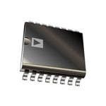
ICGOO电子元器件商城为您提供AD5542ABRUZ由Analog设计生产,在icgoo商城现货销售,并且可以通过原厂、代理商等渠道进行代购。 AD5542ABRUZ价格参考。AnalogAD5542ABRUZ封装/规格:数据采集 - 数模转换器, 16 位 数模转换器 1 16-TSSOP。您可以下载AD5542ABRUZ参考资料、Datasheet数据手册功能说明书,资料中有AD5542ABRUZ 详细功能的应用电路图电压和使用方法及教程。
AD5542ABRUZ 是 Analog Devices Inc. 生产的一款高性能数模转换器(DAC),广泛应用于需要高精度、高分辨率和低噪声特性的数据采集系统中。以下是该型号的主要应用场景:

1. 工业自动化与控制:在工业控制系统中,AD5542ABRUZ 可用于将数字信号转换为模拟信号,以驱动传感器、执行器和其他控制设备。其高精度和稳定性确保了系统的可靠性和准确性。

2. 测试与测量设备:该器件适用于各种精密测试仪器,如示波器、信号发生器等。它能够提供精确的模拟输出,帮助工程师进行复杂的信号分析和测试。

3. 通信系统:在通信领域,AD5542ABRUZ 可用于生成高质量的模拟信号,支持调制解调器、收发器等设备的工作。其低噪声特性有助于提高通信质量,减少干扰。

4. 医疗设备:对于医疗成像设备(如超声、CT 等)和监护仪器(如心电图机),AD5542ABRUZ 的高精度和低功耗特性使其成为理想选择。它可以确保图像和数据的准确性和可靠性。

5. 音频处理:在专业音频设备中,AD5542ABRUZ 可用于将数字音频信号转换为模拟信号,实现高质量的声音再现。其出色的线性度和低失真性能保证了音频的纯净度。

6. 航空航天与国防:在这些对可靠性和精度要求极高的领域,AD5542ABRUZ 能够满足严苛的应用需求。例如,它可以用于导航系统、雷达设备等,提供稳定的模拟信号输出。

总之,AD5542ABRUZ 凭借其卓越的性能和广泛的适用性,在多个行业中发挥着重要作用,特别是在那些需要高精度和稳定性的应用场合。
| 参数 | 数值 |
| 产品目录 | 集成电路 (IC)半导体 |
| 描述 | IC DAC 16BIT SRL 16TSSOP数模转换器- DAC 16b 2LSB 2.7-5.5V w/ CLR Vlogic |
| DevelopmentKit | EVAL-AD5542ASDZ |
| 产品分类 | |
| 品牌 | Analog Devices |
| 产品手册 | |
| 产品图片 |
|
| rohs | 符合RoHS无铅 / 符合限制有害物质指令(RoHS)规范要求 |
| 产品系列 | 数据转换器IC,数模转换器- DAC,Analog Devices AD5542ABRUZnanoDAC™ |
| 数据手册 | |
| 产品型号 | AD5542ABRUZ |
| 产品培训模块 | http://www.digikey.cn/PTM/IndividualPTM.page?site=cn&lang=zhs&ptm=26125http://www.digikey.cn/PTM/IndividualPTM.page?site=cn&lang=zhs&ptm=26140http://www.digikey.cn/PTM/IndividualPTM.page?site=cn&lang=zhs&ptm=26150http://www.digikey.cn/PTM/IndividualPTM.page?site=cn&lang=zhs&ptm=26146http://www.digikey.cn/PTM/IndividualPTM.page?site=cn&lang=zhs&ptm=26147 |
| 产品种类 | 数模转换器- DAC |
| 位数 | 16 |
| 供应商器件封装 | 16-TSSOP |
| 分辨率 | 16 bit |
| 包装 | 管件 |
| 商标 | Analog Devices |
| 安装类型 | 表面贴装 |
| 安装风格 | SMD/SMT |
| 封装 | Tube |
| 封装/外壳 | 16-TSSOP(0.173",4.40mm 宽) |
| 封装/箱体 | TSSOP-16 |
| 工作温度 | -40°C ~ 85°C |
| 工厂包装数量 | 96 |
| 建立时间 | 1µs |
| 接口类型 | SPI |
| 数据接口 | DSP,MICROWIRE™,QSPI™,串行,SPI™ |
| 最大功率耗散 | 1.5 mW |
| 最大工作温度 | + 85 C |
| 最小工作温度 | - 40 C |
| 标准包装 | 1 |
| 电压参考 | External |
| 电压源 | 单电源 |
| 电源电压-最大 | 5.5 V |
| 电源电压-最小 | 2.7 V |
| 积分非线性 | +/- 1 LSB |
| 稳定时间 | 1 us |
| 系列 | AD5542A |
| 结构 | Segment |
| 设计资源 | |
| 转换器数 | 1 |
| 转换器数量 | 1 |
| 输出数和类型 | 1 电压,单极 |
| 输出类型 | Voltage |
| 采样率(每秒) | - |


- 商务部:美国ITC正式对集成电路等产品启动337调查
- 曝三星4nm工艺存在良率问题 高通将骁龙8 Gen1或转产台积电
- 太阳诱电将投资9.5亿元在常州建新厂生产MLCC 预计2023年完工
- 英特尔发布欧洲新工厂建设计划 深化IDM 2.0 战略
- 台积电先进制程称霸业界 有大客户加持明年业绩稳了
- 达到5530亿美元!SIA预计今年全球半导体销售额将创下新高
- 英特尔拟将自动驾驶子公司Mobileye上市 估值或超500亿美元
- 三星加码芯片和SET,合并消费电子和移动部门,撤换高东真等 CEO
- 三星电子宣布重大人事变动 还合并消费电子和移动部门
- 海关总署:前11个月进口集成电路产品价值2.52万亿元 增长14.8%


PDF Datasheet 数据手册内容提取
2.7 V to 5.5 V, Serial-Input, Voltage-Output, 12-/16-Bit DAC Data Sheet AD5512A/AD5542A FEATURES FUNCTIONAL BLOCK DIAGRAM 12-/16-bit resolution VDD 1 LSB INL RFB 11.8 nV/√Hz noise spectral density RFB INV 1 µs settling time REFF RINV 1.1 nV-sec glitch energy 16-BIT DAC VOUT 0.05 ppm/°C temperature drift REFS AGNDF 5 kV HBM ESD classification 0.375 mW power consumption at 3 V VLOGIC 16-BIT DAC LATCH AGNDS CS 2.7 V to 5.5 V single-supply operation CONTROL LDAC LOGIC Hardware CLR and LDAC functions SCLK SERIAL INPUT REGISTER 50 MHz SPI-/QSPI-/MICROWIRE-/DSP-compatible interface DIN AD5512A/ Power-on reset clears DAC output to midscale Av1a6il-alebaled i TnS 3S mOPm × 3 mm, 10-/16-lead LFCSP and CLR DGND AD5542A 09199-001 Figure 1. 16-Lead TSSOP and 16-Lead LFCSP APPLICATIONS GND Automatic test equipment 10 Precision source-measure instruments AD5542A-1 RFB 8 RFB Data acquisition systems RINV 7 INV Medical and aerospace instrumentation REF 1 16-BIT DAC 6 VOUT Communication equipment CS 2 16-BIT DAC LATCH CLR 5 CONTROL SCLK 3 LOGIC GENERAL DESCRIPTION DIN 4 SERIAL INPUT REGISTER Tunhbeu AffDer5e5d1 v2oAl/tAagDe 5o5u4tp2Aut adrieg istianlg-tleo,- 1an2-a/l1o6g- cboitn, vseerrtiearl si n(DpuAtC, ) VD9D 09199-002 that operate from a single 2.7 V to 5.5 V supply. The DAC Figure 2. 10-Lead LFCSP output range extends from 0 V to V and is guaranteed REF Table 1. Related Devices monotonic, providing 1 LSB INL accuracy at 16 bits without Part No. Description adjustment over the full specified temperature range of −40°C AD5040/AD5060 2.7 V to 5.5 V 14-/16-bit buffed output DACs to +85°C (AD5542A) or −40°C to +125°C (AD5512A). AD5541/AD5542 2.7 V to 5.5 V 16-bit voltage outputDACs Offering unbuffered outputs, the AD5512A/AD5542A achieve AD5781/AD5791 18-/20-bit voltage output DACs a 1 μs settling time with low offset errors ideal for high speed AD5570 16-bit ±12 V/±15 V bipolaroutputDAC open loop control. AD5024/AD5064 4.5V to 5.5 V, 12-/16-bit quad channel DAC The AD5512A/AD5542A incorporate a bipolar mode of AD5764 16-bit, bipolar, voltage output DAC operation that generates a ±V output swing. The REF AD5512A/AD5542A also include Kelvin sense connections for PRODUCT HIGHLIGHTS the reference and analog ground pins to reduce layout sensitivity. 1. 16-bit performance without adjustment. The AD5512A/AD5542A are available in a 16-lead LFCSP with 2. 2.7 V to 5.5 V single supply operation. the AD5542A also available in a 10-lead LFCSP and a 16-lead 3. Low 11.8 nV/√Hz noise spectral density. TSSOP. The AD5512A/AD5542A use a versatile 3-wire interface 4. Low 0.05 ppm/°C temperature drift. that is compatible with 50 MHz SPI, QSPI™, MICROWIRE™, and 5. 3 mm × 3 mm LFCSP and TSSOP packaging. DSP interface standards. Rev. C Document Feedback Information furnished by Analog Devices is believed to be accurate and reliable. However, no responsibility is assumed by Analog Devices for its use, nor for any infringements of patents or other One Technology Way, P.O. Box 9106, Norwood, MA 02062-9106, U.S.A. rights of third parties that may result from its use. Specifications subject to change without notice. No license is granted by implication or otherwise under any patent or patent rights of Analog Devices. Tel: 781.329.4700 ©2010–2017 Analog Devices, Inc. All rights reserved. Trademarks and registered trademarks are the property of their respective owners. Technical Support www.analog.com
AD5512A/AD5542A Data Sheet TABLE OF CONTENTS Features .............................................................................................. 1 Unipolar Output Operation ...................................................... 15 Applications ....................................................................................... 1 Bipolar Output Operation ......................................................... 16 General Description ......................................................................... 1 Output Amplifier Selection ....................................................... 17 Functional Block Diagram .............................................................. 1 Force Sense Amplifier Selection ............................................... 17 Product Highlights ........................................................................... 1 Reference and Ground ............................................................... 17 Revision History ............................................................................... 2 Power-On Reset .......................................................................... 17 Specifications ..................................................................................... 3 Power Supply and Reference Bypassing .................................. 17 AD5512A ....................................................................................... 3 Applications Information .............................................................. 18 AD5542A ....................................................................................... 4 Microprocessor Interfacing ....................................................... 18 AC Characteristics ........................................................................ 5 AD5512A/AD5542A to ADSP-BF531 Interface .................... 18 Timing Characteristics ................................................................ 6 AD5512A/AD5542A to SPORT Interface .............................. 18 Absolute Maximum Ratings ............................................................ 7 AD5512A/AD5542A to 68HC11/68L11 Interface ................... 18 ESD Caution .................................................................................. 7 AD5512A/AD5542A to MICROWIRE Interface .................. 18 Pin Configuration and Function Descriptions ............................. 8 Layout Guidelines....................................................................... 19 Typical Performance Characteristics ........................................... 10 Galvanically Isolated Interface ................................................. 19 Terminology .................................................................................... 14 Decoding Multiple DACs .......................................................... 19 Theory of Operation ...................................................................... 15 Outline Dimensions ....................................................................... 20 Digital-to-Analog Section ......................................................... 15 Ordering Guide .......................................................................... 21 Serial Interface ............................................................................ 15 REVISION HISTORY 2/2017—Rev. B to Rev. C Changes to Figure 4 and Table 7 ..................................................... 8 4/2015—Rev. A to Rev. B Changes to Power-On Reset Section ............................................ 17 Deleted AD5512A/AD5542A to ADSP-2101 Interface Section .. 18 Updated Outline Dimensions ....................................................... 20 Changes to Ordering Guide .......................................................... 21 5/2011—Rev. 0 to Rev. A Changes to Table 3, Power Dissipation Value and Endnote 1 .... 4 Changes to Table 5 ............................................................................ 6 Changes to Ordering Guide .......................................................... 21 10/2010—Revision 0: Initial Version Rev. C | Page 2 of 21
Data Sheet AD5512A/AD5542A SPECIFICATIONS AD5512A VDD = 2.7 V to 5.5 V, VLOGIC = 2.7 V to 5.5 V, VREF = 2.5 V, AGND = DGND = 0 V, −40°C < TA < +125°C, unless otherwise noted. Table 2. Parameter1 Min Typ Max Unit Test Condition STATIC PERFORMANCE Resolution 12 Bits Relative Accuracy (INL) ±0.5 ±1.0 LSB Differential Nonlinearity (DNL) ±0.5 ±1.0 LSB Guaranteed monotonic Gain Error +0.5 ±2 LSB Gain Error Temperature Coefficient ±0.1 ppm/°C Unipolar Zero-Code Error 0.03 ±0.5 LSB Unipolar Zero-Code Temperature Coefficient ±0.05 ppm/°C Bipolar Resistor Matching 1 Ω/Ω R /R , typically R = R = 28 kΩ FB INV FB INV ±0.02 ±0.08 % Ratio error Bipolar Zero Offset Error ±0.07 ±2 LSB Bipolar Zero Temperature Coefficient ±0.2 ppm/°C Bipolar Zero-Code Offset Error ±0.02 ±0.5 LSB Bipolar Gain Error ±0.07 ±2 LSB Bipolar Gain Temperature Coefficient ±0.1 ppm/°C OUTPUT CHARACTERISTICS Output Voltage Range 0 V − 1 LSB V Unipolar operation REF −V +V − 1 LSB V Bipolar operation REF REF DAC Output Impedance 6.25 kΩ Tolerance typically 20% Power Supply Rejection Ratio ±1.0 LSB ΔV ± 10% DD Output Noise Spectral Density 11.8 nV/√Hz DAC code = 0x840 (AD5512A) or 0x8400 (AD5542A), frequency = 1 kHz, unipolar mode Output Noise 0.134 μV p-p 0.1 Hz to 10 Hz, unipolar mode DAC REFERENCE INPUT2 Reference Input Range 2.0 V V DD Reference Input Resistance3 9 kΩ Unipolar operation 7.5 kΩ Bipolar operation Reference Input Capacitance 26 pF Code 0x0000 26 pF Code 0x3FFF LOGIC INPUTS Input Current ±1 μA Input Low Voltage, V 0.8 V V = 2.7 V to 5.5 V INL DD Input High Voltage, V 2.4 V V = 2.7 V to 5.5 V INH DD Input Capacitance2 10 pF Hysteresis Voltage2 0.15 V POWER REQUIREMENTS V 2.7 5.5 V All digital inputs at 0 V, V , or V DD LOGIC DD I 125 150 µA V = V or V and V = GND DD IH LOGIC DD IL V 1.8 5.5 V LOGIC I 15 24 µA All digital inputs at 0 V, V , or V LOGIC LOGIC DD Power Dissipation 1.5 6.05 mW 1 Temperatures are as follows: A version −40°C to +125°C. 2 Guaranteed by design, not subject to production test. 3 Reference input resistance is code-dependent, minimum at 0x855. Rev. C | Page 3 of 21
AD5512A/AD5542A Data Sheet AD5542A VDD = 2.7 V to 5.5 V, VLOGIC = 2.7 V to 5.5 V, VREF = 2.5 V, AGND = DGND = 0 V, −40°C < TA < +85°C, unless otherwise noted. Table 3. Parameter1 Min Typ Max Unit Test Condition STATIC PERFORMANCE Resolution 16 Bits Relative Accuracy (INL) ±0.5 ±1.0 LSB B grade ±2.0 A grade Differential Nonlinearity (DNL) ±0.5 ±1.0 LSB Guaranteed monotonic Gain Error +0.5 ±2 LSB T = 25°C A ±3 LSB Gain Error Temperature Coefficient ±0.1 ppm/°C Unipolar Zero-Code Error 0.3 ±0.7 LSB T = 25°C A ±1.5 LSB Unipolar Zero-Code Temperature Coefficient ±0.05 ppm/°C Bipolar Resistor Matching 1.000 Ω/Ω R /R , typically R = R = 28 kΩ FB INV FB INV ±0.0015 ±0.0076 % Ratio error Bipolar Zero Offset Error ±1 ±5 LSB T = 25°C A ±6 LSB Bipolar Zero Temperature Coefficient ±0.2 ppm/°C Bipolar Zero-Code Offset Error ±1 ±5 LSB T = 25°C A ±6 LSB Bipolar Gain Error ±1 ±5 LSB T = 25°C A ±6 LSB Bipolar Gain Temperature Coefficient ±0.1 ppm/°C OUTPUT CHARACTERISTICS Output Voltage Range 0 V − 1 LSB V Unipolar operation REF −V +V − 1 LSB V Bipolar operation REF REF DAC Output Impedance 6.25 kΩ Tolerance typically 20% Power Supply Rejection Ratio ±1.0 LSB ΔV ± 10% DD Output Noise Spectral Density 11.8 nV/√Hz DAC code = 0x840 (AD5512A) or 0x8400 (AD5542A), frequency = 1 kHz, unipolar mode Output Noise 0.134 μV p-p 0.1 Hz to 10 Hz DAC REFERENCE INPUT2 Reference Input Range 2.0 V V DD Reference Input Resistance3 9 kΩ Unipolar operation 7.5 kΩ Bipolar operation Reference Input Capacitance 26 pF Code 0x0000 26 pF Code 0xFFFF LOGIC INPUTS Input Current ±1 μA Input Low Voltage, V 0.8 V V = 2.7 V to 5.5 V INL DD Input High Voltage, V 2.4 V V = 2.7 V to 5.5 V INH DD Input Capacitance2 10 pF Hysteresis Voltage2 0.15 V POWER REQUIREMENTS V 2.7 5.5 V All digital inputs at 0 V, V , or V DD LOGIC DD I 125 150 µA V = V or V and V = GND DD IH LOGIC DD IL V 1.8 5.5 V LOGIC I 15 24 µA All digital inputs at 0 V, V , or V LOGIC LOGIC DD Power Dissipation 0.625 0.825 mW 1 For 2.7 V ≤ VLOGIC ≤ 5.5 V, temperatures are as follows: A, B versions −40°C to +85°C. 2 Guaranteed by design, not subject to production test. 3 Reference input resistance is code-dependent, minimum at 0x8555. Rev. C | Page 4 of 21
Data Sheet AD5512A/AD5542A AC CHARACTERISTICS VDD = 2.7 V to 5.5 V, VLOGIC = 2.7 V to 5.5 V, 2.5 V ≤ VREF ≤ VDD, AGND = DGND = 0 V, −40°C < TA < +125°C, unless otherwise noted. Table 4. Parameter Min Typ Max Unit Test Condition Output Voltage Settling Time 1 μs To 1/2 LSB of FS, CL = 10 pF Slew Rate 17 V/µs C = 10 pF, measured from 0% to 63% L Digital-to-Analog Glitch Impulse 1.1 nV-sec 1 LSB change around major carry Reference −3 dB Bandwidth 2.2 MHz All 1s loaded Reference Feedthrough 1 mV p-p All 0s loaded, V = 1 V p-p at 100 kHz REF Digital Feedthrough 0.2 nV-sec Signal-to-Noise Ratio 92 dB Spurious Free Dynamic Range 80 dB Digitally generated sine wave at 1 kHz Total Harmonic Distortion 74 dB DAC code = 0x3FFF (AD5512A) or 0xFFFF (AD5542A), frequency 10 kHz, VREF = 2.5 V ± 1 V p-p Rev. C | Page 5 of 21
AD5512A/AD5542A Data Sheet TIMING CHARACTERISTICS V = 5 V, 2.5 V ≤ V ≤ V , V = 90% of V , V = 10% of V , AGND = DGND = 0 V, unless otherwise noted. DD REF DD INH LOGIC INL LOGIC Table 5. Parameter1, 2 Limit 1.8 ≤ V ≤ 2.7 V3 Limit 2.7 V ≤ V ≤ 5.5 V4 Unit Description LOGIC LOGIC f 14 50 MHz max SCLK cycle frequency SCLK t 70 20 ns min SCLK cycle time 1 t 35 10 ns min SCLK high time 2 t 35 10 ns min SCLK low time 3 t 5 5 ns min CS low to SCLK high setup 4 t 5 5 ns min CS high to SCLK high setup 5 t 5 5 ns min SCLK high to CS low hold time 6 t 10 5 ns min SCLK high to CS high hold time 7 t 35 10 ns min Data setup time 8 t 5 4 ns min Data hold time (V = 90% of V , V = 10% of V ) 9 INH DD INL DD t 5 5 ns min Data hold time (V = 3 V, V = 0 V) 9 INH INL t 20 20 ns min LDAC pulsewidth 10 t 10 10 ns min CS high to LDAC low setup 11 t 15 15 ns min CS high time between active periods 12 t 15 15 ns CLR pulsewidth 13 1 Guaranteed by design and characterization, not production tested. 2 All input signals are specified with tR = tF = 1 ns/V and timed from a voltage level of (VINL + VINH)/2. 3 −40°C < TA < +105°C. 4 −40°C < TA < +125°C. t1 SCLK t6 t2 t3 t5 t4 t7 CS t12 t8 t9 DIN DB151 DB112 t11 t10 LDAC t13 CLR N12O..T FFEOOSRR AADD55554122AA == DDBB1151.. 09199-003 Figure 3. Timing Diagram Rev. C | Page 6 of 21
Data Sheet AD5512A/AD5542A ABSOLUTE MAXIMUM RATINGS T = 25°C, unless otherwise noted. Stresses at or above those listed under Absolute Maximum A Ratings may cause permanent damage to the product. This is a Table 6. stress rating only; functional operation of the product at these Parameter Rating or any other conditions above those indicated in the operational V to AGND −0.3 V to +6 V DD section of this specification is not implied. Operation beyond Digital Input Voltage to DGND −0.3 V to V + 0.3 V DD the maximum operating conditions for extended periods may V to AGND −0.3 V to V + 0.3 V OUT DD affect product reliability. AGNDF, AGNDS to DGND −0.3 V to +0.3 V Input Current to Any Pin Except Supplies ±10 mA Operating Temperature Range ESD CAUTION AD5512A Industrial (A Version) −40°C to +125°C AD5542A Industrial (A, B Versions) −40°C to +85°C Storage Temperature Range −65°C to +150°C Maximum Junction Temperature (T max) 150°C J Package Power Dissipation (TJ max − TA)/θJA Thermal Impedance, θ JA TSSOP (RU-16) 113°C/W LFCSP (CP-16-22) 73°C/W LFCSP (CP-10-9) 74°C/W Lead Temperature, Soldering Peak Temperature1 260°C ESD2 5 kV 1 As per JEDEC Standard 20. 2 HBM classification. Rev. C | Page 7 of 21
AD5512A/AD5542A Data Sheet PIN CONFIGURATION AND FUNCTION DESCRIPTIONS AD5512A/AD5542A C IG RBF VDD VOL VNI 6 5 4 3 1 1 1 1 VOUT 1 12 DGND TOP AGNDF 2 VIEW 11 LDAC AGNDS 3 (SNcoatl eto) 10 CLR REF 1 10 GND REFS 4 9 DIN CS 2 9 VDD AD5542A-1 5 6 7 8 SCLK 3 TOP VIEW 8 RFB F S C K DIN 4 (Not to Scale) 7 INV F C N L ER CS CLR 5 6 VOUT NOTES 12 .. NTTINHOC ET =TH EHNISXEO P CP OCAOOSSIENNEDTN, GEPOCNAFTDD L.. OSHWOEUSLTD P BOET ETNIETDIAL, 09199-036 N1 . O TTINTHOE TE STH EHIXSEP CPOAOSSIENEDT, GPONAFDD L. OSHWOEUSLTD P BOET ETNIETDIAL, 09199-034 Figure 4. AD5512A/AD5542A 16-Lead LFCSP Pin Configuration Figure 5. AD5542A-1 10-Lead LFCSP Pin Configuration Table 7. AD5512A/AD5542A Pin Function Descriptions Pin No. 16-Lead 10-Lead LFCSP LFCSP Mnemonic Description 1 6 V Analog Output Voltage from the DAC. OUT 2 AGNDF Ground Reference Point for Analog Circuitry (Force). 3 AGNDS Ground Reference Point for Analog Circuitry (Sense). 4 REFS Voltage Reference Input (Sense) for the DAC. Connect to an external 2.5 V reference. Reference can range from 2 V to V . DD 5 REFF Voltage Reference Input (Force) for the DAC. Connect to an external 2.5 V reference. Reference can range from 2 V to V . DD 6 2 CS Logic Input Signal. The chip select signal is used to frame the serial data input. 7 NC No Connect. 8 3 SCLK Clock Input. Data is clocked into the input register on the rising edge of SCLK. Duty cycle must be between 40% and 60%. 9 4 DIN Serial Data Input. This device accepts 16-bit words. Data is clocked into the input register on the rising edge of SCLK. 10 5 CLR Asynchronous Clear Input. The CLR input is falling edge sensitive. When CLR is low, all LDAC pulses are ignored. When CLR is activated, the DAC register is cleared to the model selectable midscale. 11 LDAC LDAC Input. When this input is taken low, the DAC register is simultaneously updated with the contents of the input register. 12 DGND Digital Ground. Ground reference for digital circuitry. 13 7 INV Connection to the Internal Scaling Resistors of the DAC. Connect the INV pin to the external op amps inverting input in bipolar mode. 14 V Logic Power Supply. LOGIC 15 9 V Analog Supply Voltage, 5 V ± 10%. DD 16 8 R Feedback Resistor Pin. In bipolar mode, connect this pin to the external op amp output. FB 1 REF Voltage Reference Input for the DAC. Connect this pin to an external 2.5 V reference. Reference can range from 2 V to V . DD 10 GND Ground. EPAD EPAD Exposed Pad The exposed pad should be tied to the point of lowest potential, in this case, GND. Rev. C | Page 8 of 21
Data Sheet AD5512A/AD5542A RFB 1 16 VDD VOUT 2 15 VLOGIC AGNDF 3 AD5542A 14 INV AGNDS 4 TOP VIEW 13 DGND (Not to Scale) REFS 5 12 LDAC REFF 6 11 CLR NC 7 10 DIN CS 8NC = NO CONNECT9 SCLK 09199-035 Figure 6. AD5542A 16-Lead TSSOP Pin Configuration Table 8. AD5542A Pin Function Descriptions Pin No. Mnemonic Description 1 R Feedback Resistor Pin. In bipolar mode, connect this pin to the external op amp output. FB 2 V Analog Output Voltage from the DAC. OUT 3 AGNDF Ground Reference Point for Analog Circuitry (Force). 4 AGNDS Ground Reference Point for Analog Circuitry (Sense). 5 REFS Voltage Reference Input (Sense) for the DAC. Connect to an external 2.5 V reference. Reference can range from 2 V to V . DD 6 REFF Voltage Reference Input (Force) for the DAC. Connect to an external 2.5 V reference. Reference can range from 2 V to V . DD 7 NC No Connect. 8 CS Logic Input Signal. The chip select signal is used to frame the serial data input. 9 SCLK Clock Input. Data is clocked into the input register on the rising edge of SCLK. Duty cycle must be between 40% and 60%. 10 DIN Serial Data Input. This device accepts 16-bit words. Data is clocked into the input register on the rising edge of SCLK. 11 CLR Asynchronous Clear Input. The CLR input is falling edge sensitive. When CLR is low, all LDAC pulses are ignored. When CLR is activated, the DAC register is cleared to the model selectable midscale. 12 LDAC LDAC Input. When this input is taken low, the DAC register is simultaneously updated with the contents of the input register. 13 DGND Digital Ground. Ground reference for digital circuitry. 14 INV Connection to the Internal Scaling Resistors of the DAC. Connect the INV pin to the external op amps inverting input in bipolar mode. 15 V Logic Power Supply. LOGIC 16 V Analog Supply Voltage, 5 V ± 10%. DD Rev. C | Page 9 of 21
AD5512A/AD5542A Data Sheet TYPICAL PERFORMANCE CHARACTERISTICS 0.50 0.50 VDD = 5V VDD = 5V VREF = 2.5V B) VREF = 2.5V TY (LSB) 0.25 RITY (LS 0.25 NEARI 0 LINEA AL NONLI–0.25 TIAL NON 0 R N INTEG–0.50 DIFFERE–0.25 –0.750 8192 16,384 24,576 3C2O,7D6E8 40,960 49,152 57,344 65,536 09199-006 –0.500 8192 16,384 24,576 3C2O,7D6E8 40,960 49,152 57,344 65,536 09199-009 Figure 7. AD5542A Integral Nonlinearity vs. Code Figure 10. AD5542A Differential Nonlinearity vs. Code 0.25 0.75 VDD = 5V VDD = 5V VREF = 2.5V B) VREF = 2.5V TY (LSB) 0 RITY (LS 0.50 NEARI–0.25 LINEA 0.25 AL NONLI–0.50 TIAL NON 0 R N INTEG–0.75 DIFFERE–0.25 –1.00 –0.50 –60 –40 –20 0 TEM20PERA4T0URE6 (0°C) 80 100 120 140 09199-007 –60 –40 –20 0 TEM20PERA4T0URE6 (0°C) 80 100 120 140 09199-010 Figure 8. AD5542A Integral Nonlinearity vs. Temperature Figure 11. AD5542A Differential Nonlinearity vs. Temperature 0.50 0.75 VREF = 2.5V VDD = 5V TA = 25°C TA = 25°C 0.25 0.50 B) DNL B) DNL S S L L OR ( 0 OR ( 0.25 R R R R E E Y Y T T RI–0.25 RI 0 A A NE NE INL LI LI –0.50 –0.25 INL –0.75 –0.50 2 3 SUPP4LY VOLTAG5E (V) 6 7 09199-008 0 1 RE2FERENCE 3VOLTAGE4 (V) 5 6 09199-011 Figure 9. AD5542A Linearity Error vs. Supply Voltage Figure 12. AD5542A Linearity Error vs. Reference Voltage Rev. C | Page 10 of 21
Data Sheet AD5512A/AD5542A 0 0.15 VDD = 5V VDD = 5V –0.1 VTAR E=F 2=5 °2C.5V 0.10 VTAR E=F 2=5 °2C.5V –0.2 B) S SB) –0.3 R (L 0.05 ERROR (L ––00..45 DE ERRO 0 GAIN –0.6 RO-CO–0.05 E –0.7 Z –0.10 –0.8 –0.9 –0.15 –40 TEMPERA25TURE (°C) 85 09199-012 –40 TEMPERA25TURE (°C) 85 09199-015 Figure 13. AD5512A/AD5542A Gain Error vs. Temperature Figure 16. AD5512A/AD5542A Zero-Code Error vs. Temperature 2.0 132 TA = 25°C VDD = 5V VREF = 2.5V 130 TA = 25°C 1.5 128 A) REFERENCE VOLTAGE CURRENT (µA) 112246 Y CURRENT (µ 1.0 VDD = 5V SVUREPFP =L Y2 .V5VOLTAGE UPPLY 122 LSUPP S 0.5 120 118 0 116 –40 TEMPERA25TURE (°C) 85 09199-013 0 1 2 VOLTA3GE (V) 4 5 6 09199-016 Figure 14. AD5512A/AD5542A Supply Current vs. Temperature Figure 17. AD5512A/AD5542A Supply Current vs. Reference Voltage or Supply Voltage 200 200 VDD = 5V 180 VREF = 2.5V TA = 25°C 160 ENT (µA)112400 RENT (µA)150 R R UR100 CU100 C E LY 80 NC P E P R U 60 E S F RE 50 40 20 0 1 2 3 4 5 6DI7GIT8AL9 IN1P0U1T1 V1O2L1T3A1G4E1 5(V1)61718192021 09199-014 00 10,000 20,000 C3O0,D00E0 (De4c0i,m00a0l) 50,000 60,000 70,000 09199-017 Figure 15. AD5512A/AD5542A Supply Current vs. Digital Input Voltage Figure 18. AD5512A/AD5542A Reference Current vs. Code Rev. C | Page 11 of 21
AD5512A/AD5542A Data Sheet VREF = 2.5V VREF = 2.5V VDD = 5V VDD = 5V TA = 25°C TA = 25°C 100 DIN (5V/DIV) 100 VOUT (1V/DIV) 90 90 VOUT (50mV/DIV) VOUT (50mV/DIV) GAIN = –216 10 10 1LSB = VREF/(2N)–1 0 0 2µs/DIV 09199-018 0.5µs/DIV 09199-021 Figure 19. AD5512A/AD5542A Digital Feedthrough Figure 22. AD5512A/AD5542A Small Signal Settling Time 1.236 5 5 +125°C CS +25°C 0 –55°C 1.234 4 –5 1.232 E (V) –10 S 3 TAG1.230 HIT OL –15 V 2 1.228 VOUT –20 1 1.226 –25 1.224 –30 0 –0.5 0 0.5TIME (ns)1.0 1.5 2.0 09199-032 90 100IDD SUPPLY1 (1µ0A) 120 09199-042 Figure 20. AD5512A/AD5542A Digital-to-Analog Glitch Impulse Figure 23. AD5512A/AD5542A Analog Supply Current Histogram 6 +125°C +25°C 2µs/DIV VREF = 2.5V –55°C VDD = 5V 5 TA = 25°C CS (5V/DIV) 100 90 4 10pF S 50pF HIT3 100pF 2 200pF 1 10 0 0 VOUT (0.5V/DIV) 09199-020 15 16 ILOGIC1 A7T RAILS (µ1A8) 19 09199-043 Figure 21. AD5512A/AD5542A Large Signal Settling Time Figure 24. AD5512A/AD5542A Digital Supply Current Histogram Rev. C | Page 12 of 21
Data Sheet AD5512A/AD5542A 10 40 VDD = 5V VDD = 5V VREF = 5V VREF = 2.5V 20 TA = 25°C TA = 25°C DATA = 0x0000 ms) 0 V r 5 E (µ Bm)–20 S d NOI (UT UT VO–40 TP 0 OU –60 –80 –5 –100 0 20 40FREQUE6N0CY (Hz)80 100 120 09199-037 0 10,000 20,000 F3R0E,0Q0U0EN4C0Y,0 (0H0z) 50,000 60,000 70,000 09199-040 Figure 25. AD5512A/AD5542A 0.1 Hz to 10 Hz Output Noise Figure 28. AD5512A/AD5542A Total Harmonic Distortion 40 10 Hz)35 VVDRDEF = = 5 2V.5V 0 s/ TA = 25°C m V r30 –10 n TY (25 Bm) DENSI20 (dREF–20 CTRAL 15 V/VOUT–30 PE –40 S10 SE VDD = 5V NOI 5 –50 VREF = 2.5V ± 0.2V 0600 700 800 9F0R0EQU1E0N00CY (H11z0)0 1200 1300 1400 09199-038 –601k 10k F1R00EkQUENCY (1HMz) 10M 100M 09199-041 Figure 26. AD5512A/AD5542A Noise Spectral Density vs. Frequency,1 kHz Figure 29. AD5512A/AD5542A Multiplying Bandwidth 14 Hz)12 s/ m V r10 n Y ( T SI 8 N E D AL 6 R T C E P 4 S E NOIS 2 VVDRDEF = = 5 2V.5V TA = 25°C 0 9600 9700 9800 99F0R0EQ1U0E,0N0C0Y 1(H0,z1)00 10,200 10,300 10,400 09199-039 Figure 27. AD5512A/AD5542A Noise Spectral Density vs. Frequency, 10 kHz Rev. C | Page 13 of 21
AD5512A/AD5542A Data Sheet TERMINOLOGY Digital-to-Analog Glitch Impulse Relative Accuracy or Integral Nonlinearity (INL) Digital-to-analog glitch impulse is the impulse injected into the For the DAC, relative accuracy or INL is a measure of the analog output when the input code in the DAC register changes maximum deviation, in LSBs, from a straight line passing state. It is normally specified as the area of the glitch in nV-sec through the endpoints of the DAC transfer function. A typical and is measured when the digital input code is changed by INL vs. code plot is shown in Figure 7. 1 LSB at the major carry transition. A digital-to-analog glitch Differential Nonlinearity (DNL) impulse plot is shown in Figure 20. DNL is the difference between the measured change and the Digital Feedthrough ideal 1 LSB change between any two adjacent codes. A specified Digital feedthrough is a measure of the impulse injected into differential nonlinearity of ±1 LSB maximum ensures mono- the analog output of the DAC from the digital inputs of the tonicity. A typical DNL vs. code plot is shown in Figure 10. DAC, but it is measured when the DAC output is not updated. Gain Error CS is held high while the SCLK and DIN signals are toggled. It Gain error is the difference between the actual and ideal analog is specified in nV-sec and is measured with a full-scale code output range, expressed as a percent of the full-scale range. change on the data bus, that is, from all 0s to all 1s and vice It is the deviation in slope of the DAC transfer characteristic versa. A typical digital feedthrough plot is shown in Figure 19. from ideal. Power Supply Rejection Ratio (PSRR) Gain Error Temperature Coefficient PSRR indicates how the output of the DAC is affected by changes Gain error temperature coefficient is a measure of the change in the power supply voltage. The power supply rejection ratio is in gain error with changes in temperature. It is expressed in quoted in terms of percent change in output per percent change ppm/°C. in V for full-scale output of the DAC. V is varied by ±10%. DD DD Zero-Code Error Reference Feedthrough Zero-code error is a measure of the output error when zero Reference feedthrough is a measure of the feedthrough from the code is loaded to the DAC register. V input to the DAC output when the DAC is loaded with all 0s. REF Zero-Code Temperature Coefficient A 100 kHz, 1 V p-p is applied to V . Reference feedthrough is REF This is a measure of the change in zero-code error with a expressed in mV p-p. change in temperature. It is expressed in mV/°C. Rev. C | Page 14 of 21
Data Sheet AD5512A/AD5542A THEORY OF OPERATION The AD5512A/AD5542A are single, 12-/16-bit, serial input, SERIAL INTERFACE voltage output DACs. They operate from a single supply The AD5512A/AD5542A are controlled by a versatile 3- or 4- ranging from 2.7 V to 5 V and consume typically 125 µA wire serial interface that operates at clock rates of up to 50 MHz with a supply of 5 V. Data is written to these devices in a and is compatible with SPI, QSPI, MICROWIRE, and DSP 12-bit (AD5512A) or 16-bit (AD5542A) word format, via a interface standards. The timing diagram is shown in Figure 3. 3- or 4-wire serial interface. To ensure a known power-up Input data is framed by the chip select input, CS. After a high- state, these parts are designed with a power-on reset function. to-low transition on CS, data is shifted synchronously and In unipolar mode, the output is reset to midscale; in bipolar latched into the input register on the rising edge of the serial mode, the output is set to 0 V. Kelvin sense connections for the clock, SCLK. Data is loaded MSB first in 12-bit (AD5512A) reference and analog ground are included on the AD5512A/ or 16-bit (AD5542A) words. After 12 (AD5512A) or 16 AD5542A. (AD5542A) data bits have been loaded into the serial input DIGITAL-TO-ANALOG SECTION register, a low-to-high transition on CS transfers the contents The DAC architecture consists of two matched DAC sections. of the shift register to the DAC. Data can be loaded to the part A simplified circuit diagram is shown in Figure 30. The DAC only while CS is low. architecture of the AD5512A/AD5542A is segmented. The four The AD5512A/AD5542A have an LDAC function that allows MSBs of the 16-bit (AD5542A)/12-bit (AD5512A) data-word the DAC latch to be updated asynchronously by bringing LDAC are decoded to drive 15 switches, E1 to E15. Each switch low after CS goes high. LDAC should be maintained high while connects one of 15 matched resistors to either AGND or V . REF data is written to the shift register. Alternatively, LDAC can be The remaining 12 bits of the data-word drive the S0 to S11 tied permanently low to update the DAC synchronously. With switches of a 12-bit voltage mode R-2R ladder network. LDAC tied permanently low, the rising edge of CS loads the data to R R VOUT the DAC. UNIPOLAR OUTPUT OPERATION 2R 2R 2R . . . . . 2R 2R 2R . . . . . 2R These DACs are capable of driving unbuffered loads of 60 kΩ. S0 S1 . . . . . S11 E1 E2 . . . . . E15 Unbuffered operation results in low supply current, typically VREF 300 μA, and a low offset error. The AD5512A/AD5542A provide a unipolar output swing ranging from 0 V to V . 12-BIT R-2R LADDER INTFOO U15R EMQSUBAsL D SEECGOMDEENDTS 09199-022 The AD5512A/AD5542A can be configured to output boREtFh unipolar and bipolar voltages. Figure 31 shows a typical Figure 30. DAC Architecture unipolar output voltage circuit. The code table for this With this type of DAC configuration, the output impedance mode of operation is shown in Table 9. is independent of code, while the input impedance seen by 5V 2.5V the reference is heavily code dependent. The output voltage is 10µF + dependent on the reference voltage, as shown in the following 0.1µF 0.1µF equation: V ×D SERIAL V = REF INTERFACE VDD REFF REFS OUT 2N CS AD820/ OP196 DIN AD5512A/ UNIPOLAR where: SCLK AD5542A VOUT OUTPUT D is the decimal data-word loaded to the DAC register. LDAC EXTERNAL N is the resolution of the DAC. DGND AGNDF AGNDS OPAMP 09199-023 For a reference of 2.5 V, the equation simplifies to the following: Figure 31. Unipolar Output 2.5×D Table 9. AD5542A Unipolar Code Table V = OUT 65,536 DAC Latch Contents MSB LSB Analog Output This gives a V of 1.25 V with midscale loaded, and 2.5 V OUT 1111 1111 1111 1111 V × (65,535/65,536) with full scale loaded to the DAC. REF 1000 0000 0000 0000 V × (32,768/65,536) = ½ V REF REF The LSB size is VREF/65,536. 0000 0000 0000 0001 VREF × (1/65,536) 0000 0000 0000 0000 0 V Rev. C | Page 15 of 21
AD5512A/AD5542A Data Sheet 2.5 V reference and the AD8628 low offset and zero-drift Assuming a perfect reference, the unipolar worst-case output reference buffer. voltage can be calculated from the following equation: V D V V V INL Table 10. AD5542A Bipolar Code Table OUTUNI 2N REF GE ZSE DAC Latch Contents where: MSB LSB Analog Output V is the unipolar mode worst-case output. 1111 1111 1111 1111 +V × (32,767/32,768) OUT−UNI REF D is the code loaded to DAC. 1000 0000 0000 0001 +V × (1/32,768) REF N is the resolution of the DAC. 1000 0000 0000 0000 0 V V is the reference voltage applied to the part. 0111 1111 1111 1111 −V × (1/32,768) REF REF V is the gain error in volts. 0000 0000 0000 0000 −V × (32,768/32,768) = −V GE REF REF V is the zero-scale error in volts. ZSE Assuming a perfect reference, the worst-case bipolar output INL is the integral nonlinearity in volts. voltage can be calculated from the following equation: BIPOLAR OUTPUT OPERATION [(V V )(2RD)V (1RD)] With the aid of an external op amp, the AD5512A/AD5542A V OUTUNI OS REF OUTBIP 1(2RD) can be configured to provide a bipolar voltage output. A typical A circuit is shown in Figure 32. The matched bipolar offset resistors, where: R and R , are connected to an external op amp to achieve FB INV V is the bipolar mode worst-case output this bipolar output swing, typically R = R = 28 kΩ. Table 10 OUT−BIP FB INV V is the unipolar mode worst-case output. shows the transfer function for this output operating mode. OUT−UNI V is the external op amp input offset voltage. Also provided on the AD5542A are a set of Kelvin connections OS RD is the R and R resistor matching error. to the analog ground inputs. The example includes the ADR421 FB INV A is the op amp open-loop gain. +5V +2.5V 10µF + 0.1µF 0.1µF RFB +5V SERIAL INTERFACE CSVDD REFF REFS RFB INV DIN AD5512A/ RINV VOUT BIPOLAR SCLK OUTPUT AD5542A LDAC –5V DGND AGNDF AGNDS EXOTPEARMNPAL 09199-024 Figure 32. Bipolar Output Rev. C | Page 16 of 21
Data Sheet AD5512A/AD5542A OUTPUT AMPLIFIER SELECTION REFERENCE AND GROUND For bipolar mode, a precision amplifier should be used and Because the input impedance is code-dependent, the refer- supplied from a dual power supply. This provides the ±V ence pin should be driven from a low impedance source. The REF output. In a single-supply application, selection of a suitable op AD5512A/AD5542A operate with a voltage reference ranging amp may be more difficult because the output swing of the ampli- from 2 V to VDD. References below 2 V result in reduced accuracy. fier does not usually include the negative rail, in this case, The full-scale output voltage of the DAC is determined by the AGND. This can result in some degradation of the specified reference. Table 9 and Table 10 outline the analog output voltage performance unless the application does not use codes near zero. or particular digital codes. For optimum performance, Kelvin sense connections are provided on the AD5512A/AD5542A. The selected op amp must have a very low-offset voltage (the DAC LSB is 38 μV for the AD5542A with a 2.5 V reference) If the application doesn’t require separate force and sense lines, to eliminate the need for output offset trims. Input bias current tie the lines close to the package to minimize voltage drops between the package leads and the internal die. should also be very low because the bias current, multiplied by the DAC output impedance (approximately 6 kΩ), adds to the POWER-ON RESET zero-code error. Rail-to-rail input and output performance is The AD5512A/AD5542A have a power-on reset function to required. For fast settling, the slew rate of the op amp should ensure that the output is at a known state on power-up. On not impede the settling time of the DAC. Output impedance power-up, the DAC register MSB is 1 and all other bits are 0 of the DAC is constant and code-independent, but to minimize until the data is loaded from the serial register. However, the gain errors, the input impedance of the output amplifier should serial register is not cleared on power-up; therefore, its contents be as high as possible. The amplifier should also have a 3 dB are undefined. When loading data initially to the DAC, 16 bits or bandwidth of 1 MHz or greater. The amplifier adds another more should be loaded to prevent erroneous data appearing on time constant to the system, thus increasing the settling time the output. If more than 16 bits are loaded, the last 16 are kept, of the output. A higher 3 dB amplifier bandwidth results in a and if less than 16 bits are loaded, bits remain from the previous shorter effective settling time of the combined DAC and amplifier. word. If the AD5512A/AD5542A must be interfaced with data FORCE SENSE AMPLIFIER SELECTION shorter than 16 bits, the data should be padded with 0s at the LSBs. Use single-supply, low-noise amplifiers. A low-output impedance at high frequencies is preferred because the amplifiers must be POWER SUPPLY AND REFERENCE BYPASSING able to handle dynamic currents of up to ±20 mA. For accurate high-resolution performance, it is recommended that the reference and supply pins be bypassed with a 10 μF tantalum capacitor in parallel with a 0.1 μF ceramic capacitor. Rev. C | Page 17 of 21
AD5512A/AD5542A Data Sheet APPLICATIONS INFORMATION MICROPROCESSOR INTERFACING AD5512A/AD5542A TO 68HC11/68L11 INTERFACE Microprocessor interfacing to the AD5512A/AD5542A is via Figure 35 shows a serial interface between the AD5512A/ a serial bus that uses standard protocol that is compatible with AD5542A and the 68HC11/68L11 microcontroller. SCK of DSP processors and microcontrollers. The communications the 68HC11/68L11 drives the SCLK of the DAC, and the channel requires a 3- or 4-wire interface consisting of a clock MOSI output drives the serial data line serial DIN. The CS signal, a data signal, and a synchronization signal. The signal is driven from one of the port lines. The 68HC11/68L11 is AD5512A/AD5542A require a 16-bit data-word with data configured for master mode: MSTR = 1, CPOL = 0, and CPHA = valid on the rising edge of SCLK. The DAC update can be 0. Data appearing on the MOSI output is valid on the rising done automatically when all the data is clocked in, or it can edge of SCK. be done under the control of the LDAC. AD5512A/AD5542A TO ADSP-BF531 INTERFACE PC6 LDAC 68HC11/ PC7 CS AD5512A/ The SPI interface of the AD5512A/AD5542A is designed to be 68L11* MOSI DIN AD5542A* easily connected to industry-standard DSPs and micro- SCK SCLK ccoann tbroe lcleornsn. Fecigteudre t o3 3t hseh oAwnsa lhoogw D tehvei cAeDs, 5I5n1c.2, AB/lAacDkf5i5n4® 2DAS P . *ADDITIONAL PINS OMITTED FOR CLARITY. 09199-026 Figure 35. AD5512A/AD5542A to 68HC11/68L11 Interface The Blackfin has an integrated SPI port that can be connected directly to the SPI pins of the AD5512A/AD5542A. AD5512A/AD5542A TO MICROWIRE INTERFACE Figure 36 shows an interface between the AD5512A/AD5542A AD5512A/ AD5542A and any MICROWIRE-compatible device. Serial data is shifted SPISELx CS out on the falling edge of the serial clock and into the AD5512A/ SCK SCLK AD5542A on the rising edge of the serial clock. No glue logic MOSI DIN is required because the DAC clocks data into the input shift ADSP-BF531 register on the rising edge. PF9 LDAC 09199-044 CS CS AD5512A/ Figure 33. AD5512A/AD5542A to ADSP-BF531 Interface MICROWIRE* SO DIN AD5542A* SCLK SCLK AThDe5 A5n1al2oAg /DAeDvic5e5s 4A2DASP T-BOF S52P7O hRasT o InNe TSPEORRFTA CseEri al port. *ADDITIONAL PINS OMITTED FOR CLARITY. 09199-027 Figure 36. AD5512A/AD5542A to MICROWIRE Interface Figure 34 shows how one SPORT interface can be used to control the AD5512A/AD5542A. AD5512A/ SPORT_TFS CS AD5542A SPORT_TSCK SCLK SPORT_DTO DIN ADSP-BF527 GPIO0 LDAC 09919-045 Figure 34. AD5512A/AD5542A to ADSP-BF527 Interface Rev. C | Page 18 of 21
Data Sheet AD5512A/AD5542A LAYOUT GUIDELINES DECODING MULTIPLE DACS In any circuit where accuracy is important, careful consider- The CS pin of the AD5512A/AD5542A can be used to select ation of the power supply and ground return layout helps to one of a number of DACs. All devices receive the same serial ensure the rated performance. Design the printed circuit board clock and serial data, but only one device receives the CS signal (PCB) on which the AD5512A/AD5542A is mounted so that at any one time. The DAC addressed is determined by the the analog and digital sections are separated and confined to decoder. There is some digital feedthrough from the digital certain areas of the board. If the AD5512A/AD5542A are in a input lines. Using a burst clock minimizes the effects of digital system where multiple devices require an analog ground-to- feedthrough on the analog signal channels. Figure 38 shows a digital ground connection, make the connection at one point typical circuit. only. Establish the star ground point as close as possible to the device. AD5512A/ SCLK AD5542A The AD5512A/AD5542A should have ample supply bypassing CS of 10 μF in parallel with 0.1 μF on each supply located as close DIN DIN VOUT VDD SCLK to the package as possible, ideally right up against the device. The 10 μF capacitors are the tantalum bead type. The 0.1 μF ENABLE EN AD5512A/ capacitor should have low effective series resistance (ESR) AD5542A CS and low effective series inductance (ESI), such as the common ADCDORDEESDS DECODER DIN VOUT ceramic types, which provide a low impedance path to ground SCLK at high frequencies to handle transient currents due to internal DGND logic switching. AD5512A/ AD5542A GALVANICALLY ISOLATED INTERFACE CS DIN VOUT In many process control applications, it is necessary to provide SCLK an isolation barrier between the controller and the unit being controlled to protect and isolate the controlling circuitry AD5512A/ from any hazardous common-mode voltages that may occur. AD5542A CS iiosCfo otlhautepi olAenrD ®i n5p5 re1ox2dcAuesc/sAt soD ffr 52o5.m54 2 kAAVn. maTlahokege sDse terhivaeilc pleoasa rpdtsrio nivdgie dsatelr fuvoocrlt tuiasrgoeel a ted DSCINLK VOUT 09199-030 Figure 38. Addressing Multiple DACs interfaces because the number of interface lines is kept to a minimum. Figure 37 shows a 4-channel isolated interface to the AD5512A/AD5542A using an ADuM1400. For further information, visit http://www.analog.com/icouplers. CONTROLLER ADuM14001 SERIAL VIA VOA TO CLOCK IN ENCODE DECODE SCLK DASTAE ROIAUTL VIB ENCODE DECODE VOB DTOIN VIC VOC TO SYNC OUT ENCODE DECODE CS LOAD DOAUCT VID ENCODE DECODE VOD TLODAC 1ADDITIONAL PINS OMITTED FOR CLARITY. 09199-046 Figure 37. Isolated Interface Rev. C | Page 19 of 21
AD5512A/AD5542A Data Sheet OUTLINE DIMENSIONS 3.10 0.30 3.00 SQ 0.23 PIN 1 2.90 0.18 INDICATOR PIN 1 0.50 13 16 INDICATOR BSC 12 1 EXPOSED 1.75 PAD 1.60 SQ 1.45 9 4 0.50 8 5 0.25 MIN TOP VIEW 0.40 BOTTOM VIEW 0.30 0.80 FOR PROPER CONNECTION OF 0.75 THE EXPOSED PAD, REFER TO 0.05 MAX THE PIN CONFIGURATION AND 0.70 0.02 NOM FUNCTION DESCRIPTIONS SECTION OF THIS DATA SHEET. COPLANARITY SEATING 0.08 PLANE 0.20 REF COMPLIANTTOJEDEC STANDARDS MO-220-WEED-6. 08-16-2010-E Figure 39. 16-Lead Lead Frame Chip Scale Package [LFCSP_WQ] 3 mm × 3 mm Body, Very Very Thin Quad (CP-16-22) Dimensions shown in millimeters 5.10 5.00 4.90 16 9 4.50 6.40 4.40 BSC 4.30 1 8 PIN 1 1.20 MAX 0.15 0.20 0.05 0.09 0.75 0.30 8° 0.60 B0.S6C5 0.19 SPELAANTIENG 0° 0.45 COPLANARITY 0.10 COMPLIANT TO JEDEC STANDARDS MO-153-AB Figure 40. 16-Lead Thin Shrink Small Outline Package [TSSOP] (RU-16) Dimensions shown in millimeters Rev. C | Page 20 of 21
Data Sheet AD5512A/AD5542A 2.48 2.38 3.10 2.23 3.00 SQ 2.90 0.50 BSC 6 10 PIN 1 INDEX EXPOSED 1.74 AREA PAD 1.64 0.50 1.49 0.40 0.30 5 1 0.20 MIN TOP VIEW BOTTOM VIEW PIN 1 INDICATOR (R 0.15) 0.80 FOR PROPER CONNECTION OF 0.75 0.05 MAX TTHHEE PEIXNP COOSNEDFI GPAUDR,A RTEIOFNE RA NTOD 0.70 0.02 NOM FUNCTION DESCRIPTIONS COPLANARITY SECTION OF THIS DATA SHEET. SEPALTAINNGE 000...223050 0.20 REF 0.08 02-05-2013-C Figure 41. 10-Lead Lead Frame Chip Scale Package [LFCSP_WD] 3 mm × 3 mm Body, Very Very Thin, Dual Lead (CP-10-9) Dimensions shown in millimeters ORDERING GUIDE Power On Temperature Model1 INL DNL Reset to Code Range Package Description Package Option Branding AD5512AACPZ-REEL7 ±1 LSB ±1 LSB Midscale −40°C to +125°C 16-Lead LFCSP_WQ CP-16-22 DFQ AD5512AACPZ-500RL7 ±1 LSB ±1 LSB Midscale −40°C to +125°C 16-Lead LFCSP_WQ CP-16-22 DFQ AD5542ABRUZ ±1 LSB ±1 LSB Midscale −40°C to +85°C 16-Lead TSSOP RU-16 AD5542ABRUZ-REEL7 ±1 LSB ±1 LSB Midscale −40°C to +85°C 16-Lead TSSOP RU-16 AD5542AARUZ ±2 LSB ±1 LSB Midscale −40°C to +85°C 16-Lead TSSOP RU-16 AD5542AARUZ-REEL7 ±2 LSB ±1 LSB Midscale −40°C to +85°C 16-Lead TSSOP RU-16 AD5542ABCPZ-REEL7 ±1 LSB ±1 LSB Midscale −40°C to +85°C 16-Lead LFCSP_WQ CP-16-22 DFL AD5542AACPZ-REEL7 ±2 LSB ±1 LSB Midscale −40°C to +85°C 16-Lead LFCSP_WQ CP-16-22 DFK AD5542ABCPZ-1-RL7 ±1 LSB ±1 LSB Midscale −40°C to +85°C 10-Lead LFCSP_WD CP-10-9 DFM AD5542ABCPZ-500RL7 ±1 LSB ±1 LSB Midscale −40°C to +85°C 16-Lead LFCSP_WQ CP-16-22 DFL EVAL-AD5542ASDZ AD5541A Evaluation Board 1 Z = RoHS Compliant Part. ©2010–2017 Analog Devices, Inc. All rights reserved. Trademarks and registered trademarks are the property of their respective owners. D09199-0-2/17(C) Rev. C | Page 21 of 21
Mouser Electronics Authorized Distributor Click to View Pricing, Inventory, Delivery & Lifecycle Information: A nalog Devices Inc.: AD5512AACPZ-REEL7 AD5542AARUZ AD5542ABCPZ-1-RL7 AD5542AACPZ-REEL7 AD5542ABRUZ EVAL- AD5542ASDZ AD5542ABCPZ-REEL7 AD5542ABRUZ-REEL7 AD5542AARUZ-REEL7