 Datasheet下载
- 型号: ACT112
- 制造商: Panasonic Corporation
- 库位|库存: xxxx|xxxx
- 要求:
| 数量阶梯 | 香港交货 | 国内含税 |
| +xxxx | $xxxx | ¥xxxx |
查看当月历史价格
查看今年历史价格
ACT112产品简介:
ICGOO电子元器件商城为您提供ACT112由Panasonic Corporation设计生产,在icgoo商城现货销售,并且可以通过原厂、代理商等渠道进行代购。 ACT112价格参考¥12.56-¥12.56。Panasonic CorporationACT112封装/规格:汽车继电器, 。您可以下载ACT112参考资料、Datasheet数据手册功能说明书,资料中有ACT112 详细功能的应用电路图电压和使用方法及教程。
Panasonic Electric Works(现为 Panasonic Industrial Devices)生产的ACT112汽车继电器是一款广泛应用于汽车电气系统的高性能继电器。以下是其主要应用场景:

 1. 汽车电气控制系统
   - ACT112继电器常用于汽车的电气控制回路中,例如启动电机、空调压缩机、电动窗、车灯、雨刷等设备的开关控制。
   - 它能够承受高电流负载,确保在频繁开关的情况下保持稳定性能。

 2. 发动机管理系统
   - 在发动机启动和运行过程中,ACT112可以用于控制燃油泵、点火系统和其他关键部件的电源通断。
   - 其高可靠性和抗电磁干扰能力使其适合复杂的发动机环境。

 3. 安全与舒适性功能
   - 该继电器可用于控制车辆的安全系统,如刹车灯、转向灯、倒车雷达等。
   - 同时也适用于提升驾驶舒适性的功能,如座椅加热、后视镜调节、天窗开合等。

 4. 新能源汽车应用
   - 在混合动力或电动汽车中,ACT112可作为辅助继电器,用于电池管理系统(BMS)、充电电路以及低压电器设备的控制。
   - 其紧凑的设计和低功耗特性非常适合对空间和效率要求较高的新能源汽车。

 5. 工业与商用车辆
   - 除了乘用车,ACT112还适用于商用车辆(如卡车、公交车)中的大功率设备控制,例如喇叭、警示灯、尾灯等。
   - 在某些工业领域,它也可用于非汽车类的高振动、高湿度环境中。

 6. 特点与优势
   - 高耐久性:支持数万次以上的开关操作,寿命长。
   - 小型化设计:节省安装空间,便于集成到复杂的汽车电子系统中。
   - 环境适应性强:能在宽温范围(-40°C至+85°C)和潮湿条件下正常工作。
   - 低接触电阻:减少能量损耗,提高系统效率。

综上所述,Panasonic ACT112继电器凭借其卓越的性能和可靠性,成为汽车行业中不可或缺的关键组件,广泛应用于各类车辆的电气控制系统中。
| 参数 | 数值 |
| 产品目录 | |
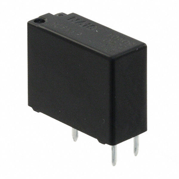
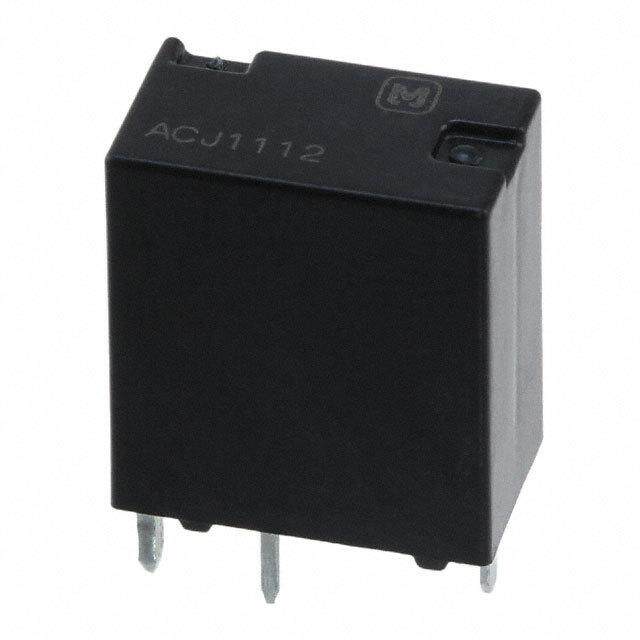
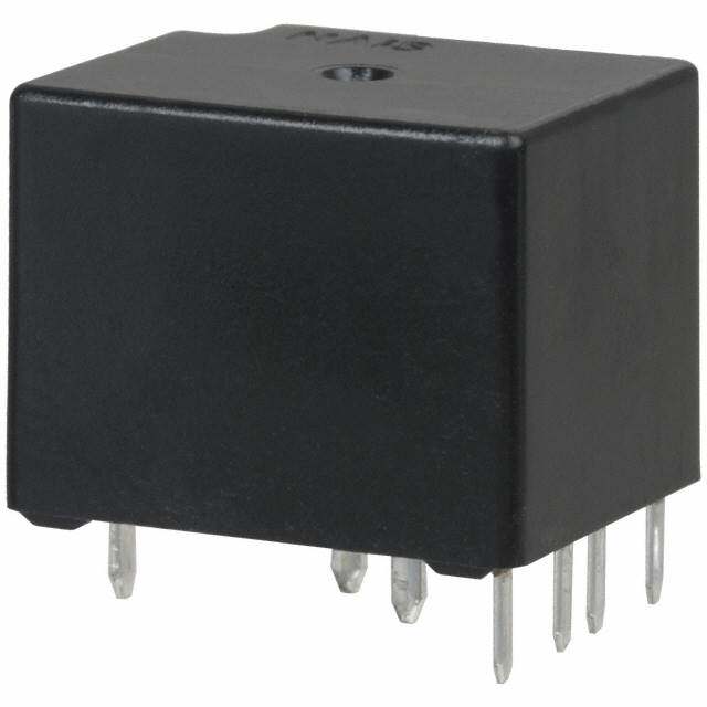
| 描述 | RELAY AUTOMOTIVE SPDT 20A 12V车用继电器 12VDC 1 FORM C 20A SLIM |
| 产品分类 | |
| 品牌 | Panasonic Electric Works |
| 产品手册 | |
| 产品图片 |
|
| rohs | RoHS 合规性豁免无铅 / 符合限制有害物质指令(RoHS)规范要求 |
| 产品系列 | 车用继电器,Panasonic Industrial Devices ACT112ACT |
| mouser_ship_limit | 该产品可能需要其他文件才能进口到中国。 |
| 数据手册 | |
| 产品型号 | ACT112 |
| 产品目录绘图 |
|
| 产品目录页面 | |
| 产品种类 | 车用继电器 |
| 关闭电压(最小值) | 1 VDC |
| 其它名称 | 255-2591 |
| 其它有关文件 | |
| 功耗 | 800 mW |
| 包装 | 管件 |
| 商标 | Panasonic Industrial Devices |
| 安装类型 | 通孔 |
| 安装风格 | Through Hole |
| 导通电压(最大值) | 7.2 VDC |
| 封装 | Tube |
| 工作时间 | 10ms |
| 工作温度 | -40°C ~ 85°C |
| 工厂包装数量 | 30 |
| 开关电压 | 14VDC -标称 |
| 标准包装 | 30 |
| 特性 | - |
| 端子类型 | PC 引脚 |
| 类型 | Automotive Relays |
| 线圈功率 | 800 mW |
| 线圈电压 | 12VDC |
| 线圈电流 | 66.7mA |
| 线圈电阻 | 180 欧姆 |
| 线圈端接 | Solder Terminal |
| 线圈类型 | 无锁存 |
| 继电器类型 | 自动 |
| 触头外形 | SPDT(1 C 型) |
| 触头材料 | 银合金,无镉 |
| 触点形式 | 1 Form C (SPDT-BM) |
| 触点材料 | Silver Alloy |
| 触点端接 | Solder Terminal |
| 释放时间 | 10ms |
| 额定接触(电流) | 20A |


- 商务部:美国ITC正式对集成电路等产品启动337调查
- 曝三星4nm工艺存在良率问题 高通将骁龙8 Gen1或转产台积电
- 太阳诱电将投资9.5亿元在常州建新厂生产MLCC 预计2023年完工
- 英特尔发布欧洲新工厂建设计划 深化IDM 2.0 战略
- 台积电先进制程称霸业界 有大客户加持明年业绩稳了
- 达到5530亿美元!SIA预计今年全球半导体销售额将创下新高
- 英特尔拟将自动驾驶子公司Mobileye上市 估值或超500亿美元
- 三星加码芯片和SET,合并消费电子和移动部门,撤换高东真等 CEO
- 三星电子宣布重大人事变动 还合并消费电子和移动部门
- 海关总署:前11个月进口集成电路产品价值2.52万亿元 增长14.8%
PDF Datasheet 数据手册内容提取
CT (ACT) SMALL & SLIM CT RELAYS (ACT) AUTOMOTIVE RELAY FEATURES TYPICAL APPLICATIONS • Terminal layout for simplifying PC • Power windows board pattern design • Auto door lock • Capable of 25A high-capacity load • Power sunroof switching with compact size • Electrically powered mirrors • Plastic sealed type • Powered seats • Lift gates • Slide door closers, etc. (for DC motor forward/reverse control circuits) ORDERING INFORMATION ACT Contact arrangement 1: 1 Form C 2: 1 Form C×2 (8 terminal) 5: 1 Form C×2 (10 terminal) Coil voltage, DC 12: 12 V TYPES Contact arrangement Coil voltage Part No. 1 Form C ACT112 1 Form C 2 (8 terminals type) 12 V DC ACT212 1 Form C 2 (10 terminals type) ACT512 Standard packing; 1 Form C: Carton (tube) 30pcs. Case 1,500pcs. 1 Form C 2: Carton (tube) 30pcs. Case 900pcs. RATING 1. Coil data Nominal operating Nominal operating Nominal coil Pick-up voltage Drop-out voltage Coil resistance current power Usable voltage range voltage (at 20C 68F) (at 20C 68F) [10%] (at 20C 68F) [10%] (at 20C 68F) (at 20C 68F) Max. 7.2 V DC Min. 1.0 V DC 12V DC 66.7 mA 180 800 mW 10 to 16V DC (Initial) (Initial) Note:Other pick-up voltage types are also available. Please contact us for details. ds_61205_en_ct: 010113J 1
CT (ACT) 2. Specifications Characteristics Item Specifications Arrangement 1 Form C 2, 1 Form C Contact Contact resistance (Initial) N.O.: Typ 7m, N.C.: Typ 10m (By voltage drop 6V DC 1A) Contact material Ag alloy (Cadmium free) Nominal switching capacity (resistive load) N.O.: 20 A 14V DC, N.C.: 10 A 14V DC N.O.: 25 A for 1 hour, 35 A for 2 minutes at 20C 68F Max. carrying current (14V DC)*3 Rating 20 A for 1 hour, 30 A for 2 minutes at 85C 185F Nominal operating power 800 mW Min. switching capacity (resistive load)*1 1 A 14V DC Insulation resistance (Initial) Min. 100 M (at 500V DC, Measurement at same location as “Breakdown voltage” section.) Breakdown voltage Between open contacts 500 Vrms for 1 min. (Detection current: 10mA) Electrical (Initial) Between contacts and coil 500 Vrms for 1 min. (Detection current: 10mA) characteristics Operate time (at nominal voltage) Max. 10ms (at 20C 68F, excluding contact bounce time) (Initial) Release time (at nominal voltage) Max. 10ms (at 20C 68F, excluding contact bounce time) (Initial) Functional Min. 100 m/s2 {10G} (Half-wave pulse of sine wave: 11ms; detection time: 10s) Shock resistance Destructive Min. 1,000 m/s2 {100G} (Half-wave pulse of sine wave: 6ms) Mechanical characteristics Functional 10 Hz to 100 Hz, Min. 44.1 m/s2 {4.5G} (Detection time: 10s) Vibration resistance 10 Hz to 500 Hz, Min. 44.1 m/s2 {4.5G}, Destructive Time of vibration for each direction; X, Y direction: 2 hours, Z direction: 4 hours Mechanical Min. 107 (at 120 cpm) <Resistive load> Min. 105 (at nominal switching capacity, operating frequency: 1s ON, 9s OFF) Expected life <Motor load> Electrical N.O. side: Min. 2 105 (at Inrush 25A, Steady 5A 14 V DC), Min. 105 (at 25A 14 V DC motor lock condition) N.C. side: Min. 2 105 (at brake current 20A 14 V DC) (operating frequency: 0.5s ON, 9.5s OFF) Ambient temperature: –40C to +85C –40F to +185F, Conditions for operation, transport and storage*2 Conditions Humidity: 5% R.H. to 85% R.H. (Not freezing and condensing at low temperature) Max. operating speed 6 cpm (at nominal switching capacity) Mass Twin type: approx. 8 g .28 oz, 1 Form C type: approx. 4 g .14 oz Notes: *1.This value can change due to the switching frequency, environmental conditions, and desired reliability level, therefore it is recommended to check this with the actual load. *2.The upper operation ambient temperature limit is the maximum temperature that can satisfy the coil temperature rise value. Refer to “6. Usage, Storage and Transport Conditions“ in AMBIENT ENVIRONMENT section in Relay Technical Information. Please inquire if you will be using the relay in a high temperature atmosphere (110C 230F). *3.Depends on connection conditions. Also, this does not guarantee repeated switching. We recommend that you confirm operation under actual conditions. If the relay is used continuously for long periods of time with coils on both sides in an energized condition, breakdown might occur due to abnormal heating depending on the carrying condition. Therefore, please inquire when using with a circuit that causes an energized condition on both sides simultaneously. REFERENCE DATA 1-(1). Coil temperature rise (at room 1-(2). Coil temperature rise (at 85C 185F) 2. Max. switching capability (Resistive load, temperature) Sample: ACT212, 3pcs. initial) Sample: ACT212, 3pcs. Contact carrying current: 0A, 10A, 20A Contact carrying current: 0A, 10A, 20A Ambient temperature: 85C 185F Ambient temperature: Room temperature (when coil powered on one side) (when coil powered on one side) (N.O. side: room temperature) 140 140 60 20A 120 C120 20A DC 50 1068000 100AA °emperature rise, 1068000 100AA witching voltage, V 4300 T S 20 40 40 20 20 10 0 0 0 12 14 16 12 14 16 0 10 20 30 40 50 Coil applied voltage, V Coil applied voltage, V Switching current, A 2 ds_61205_en_ct: 010113J
CT (ACT) 3. Ambient temperature and operating voltage 4. Distribution of pick-up and drop-out voltage 5. Distribution of operate and release time range Sample: ACT212, 40pcs. Sample: ACT212, 40pcs. * Without diode 40 50 35 Pick-up voltage Operate time C 35 Drop-out voltage 20 Release time D V 40 pplied voltage, 322050 Operating voltage range Quantity, n 30 Quantity, n 221505 oil a 15 20 C 10 10 10 5 5 0−40−P20ick-u0p vo2lt0age 4(C0old6 s0tart8)085100120 00 1 1.52.02.53.03.54.04.55.05.56.06.57.07.5 01.0 1.1 1.2 1.3 1.4 1.5 1.6 1.7 1.8 1.9 2.0 Ambient temperature, °C Voltage, V Operate and release time, ms 6-(1). Electrical life test (Motor free) Change of pick-up and drop-out voltage Change of contact resistance Sample: ACT212, 3pcs. Load: Inrush 25A, steady 5A Brake current: 13A 14V DC, 10 50 Power window motor actual load (free condition) V Contact welding: 0 time OACmiprceburiaeitt:nint gte fmrepqeureantucrye:: ORNo o0m.5 ste, mOpFeFr a9tS.u5arsemple Pick-up and drop-out voltage, 2468 DPriocpk--ouupt vvooMllttaaisggceeontact: 0 timeMMMMXXaaiinnxx.... ΩContact resistance, m 43210000 Max. M X Min. 0 0 0 10 20 0 10 20 No. of operations, × 104 No. of operations, × 104 Load current waveform Inrush current: 25A, Steady current: 6A Brake current: 13A 10A 100ms ds_61205_en_ct: 010113J 3
CT (ACT) 6-(2). Electrical life test (Motor lock) Change of pick-up and drop-out voltage Change of contact resistance Sample: ACT212, 3pcs. Load: 25A 14V DC Power window motor actual load (lock condition) 10 50 SACwmircibtucieiht:nint gte fmrepqeureantucyre: :O RNo o0m.5 ste, mOpFeFr a9t.Su5arsempMle Pick-up and drop-out voltage, V 2468 DPriocpk--oCuupot n vvtooaMllcttaatis ggwceeoenldtiancgt:: 00 ttiimmeeMMMMXXaaiinnxx.... ΩContact resistance, m 43210000 Max. X Min. 0 0 0 5 10 0 5 10 No. of operations, × 104 No. of operations, × 104 Load current waveform 5A 100ms 6-(3). Electrical life test (Motor lock) Change of pick-up and drop-out voltage Change of contact resistance Sample: ACT212, 3pcs. Load: 20A 14V DC, door lock motor actual load (Lock condition) 10 50 Switching frequency: ON 0.3s, OFF 19.7s V Ambient temperature: Room temperature ge, 9 Ω Circuit: Sample ut volta 87 Pick-up voltage Max. nce, m 40 Side1 M M M M M MM Pick-up and drop-o 4653 Drop-out voltage MMXXainx.. Contact resista 2300 Side2 2 Min. 10 Max. 1 X Min. 0 0 0 5 10 0 5 10 No. of operations, × 104 No. of operations, × 104 Relay 1 Relay 2 0.3s 9.7s 0.3s 9.7s 20s (1 cycle) Load current waveform 5A 100ms 4 ds_61205_en_ct: 010113J
CT (ACT) DIMENSIONS (mm inch) Download CCAADD DDaattaa from our Web site. 1. Twin type (8 terminals) External dimensions PC board pattern (Bottom view) CAD Data 17.4 14 9.5 .685 .551 .374 6 .236 4.3 .169 2.5 13.5 3 .098 .531 6.8.118 .00.146 Max..0 13.90 .2683.1.1254 4.1.369 .133.85 0.4 1 *A 44××.10.54+ 5 0 0 .+ 1 00 .0 d4 iad.ia. .51951 44××1.0.14+ 3 0 0 .+ 1 00 .0d 4 i ad.ia. .016 .039 .0139 0.3 0.8 0.4 0.4 Tolerance: 0.1 .004 .012 .031 .016.016 .10.4259 .2636 .93.754 Pre-soldering Schematic (Bottom view) 1 4.3 .039 .169 COIL 2.5 3 .098 COM NC 6.8 .118 .268 3.15 4.3 Dimension: Tolerance NO .124 .169 Max. 1mm .039 inch: 0.1 .004 COIL 1 to 3mm .039 to .118 inch:0.2 .008 COM 1.45 .51951 Min. 3mm .118 inch: 0.3 .012 .057 * Dimensions (thickness and width) of terminal is measured before pre-soldering. Intervals between terminals is measured at A surface level. 2. Twin type (10 terminals) External dimensions PC board pattern (Bottom view) CAD Data 17.4 14 9.5 .685 .551 .374 6 .236 4.3 3.15 .169 .124 13.5 2.5 .531 6.80.0.6256 .098 .00.146 Max..0 13.90 .2683.1.1254 4.1.369 .133.85.001.46 .0319 .0139 .001.32 *A .003.81 .00.146.001.46 0.0.6256 66××1.0.45+ 5 0 0 .+ 1 00 .0 d4 i ad.ia. .51951Tolerance: 44××0.10..141+ 3 00 .+ 1 00 . .0 d40 iad0.ia4. 9.5 1.25 .374 Pre-soldering .049 6 .236 Schematic (Bottom view) 3.1.1245 4.1.369 NO 2.5 COIL 0.65 .098 COM NC 6.8 .026 Dimension: Tolerance .268 .31.2154 4.1.369 Max. 1mm .039 inch: 0.1 .004 NO 1.45 COIL .057 1 to 3mm .039 to .118 inch:0.2 .008 COM NC 0.65 1 15 Min. 3mm .118 inch: 0.3 .012 .026 .039 .591 * Dimensions (thickness and width) of terminal is measured before pre-soldering. Intervals between terminals is measured at A surface level. ds_61205_en_ct: 010113J 5
CT (ACT) 3. Slim 1c type External dimensions PC board pattern (Bottom view) CAD Data 17.4 7.2 3×1.4 dia. .685 .283 3×.055 dia. 9.5 .374 6 .236 4.3 13.5 3.15 .169 .531 .124 .001.46 Max..0 13.90 0.0.6256 .51951 22××.10.41+ 3 0 0 .+ 1 00 .0 d4 iad.ia. 3.5 Tolerance: 0.1 .004 .138 *A 0.4 1 0.8 .016 .039 .0139 0.3 .031 0.4 0.4 Schematic (Bottom view) .012 .016 .016 .10.4295 6 .397.54 Pre-soldering NO COIL .236 .0391 Dimension: Tolerance COM NC 3.15 4.3 .124 .169 Max. 1mm .039 inch: 0.1 .004 1 to 3mm .039 to .118 inch:0.2 .008 1.45 0.65 15 Min. 3mm .118 inch: 0.3 .012 .057 .006 .591 * Dimensions (thickness and width) of terminal is measured before pre-soldering. Intervals between terminals is measured at A surface level. EXAMPLE OF CIRCUIT Forward/reverse control circuits of DC motor for power windows NO NO COM M COM 12 V DC NC NC SW A SW B M : Power window motor For Cautions for Use, see Relay Technical Information. 6 ds_61205_en_ct: 010113J