ICGOO在线商城 > 电阻器 > 芯片电阻 - 表面安装 > AC0402FR-0712K1L
 Datasheet下载
- 型号: AC0402FR-0712K1L
- 制造商: YAGEO AMERICA CORPORATION
- 库位|库存: xxxx|xxxx
- 要求:
| 数量阶梯 | 香港交货 | 国内含税 |
| +xxxx | $xxxx | ¥xxxx |
查看当月历史价格
查看今年历史价格
AC0402FR-0712K1L产品简介:
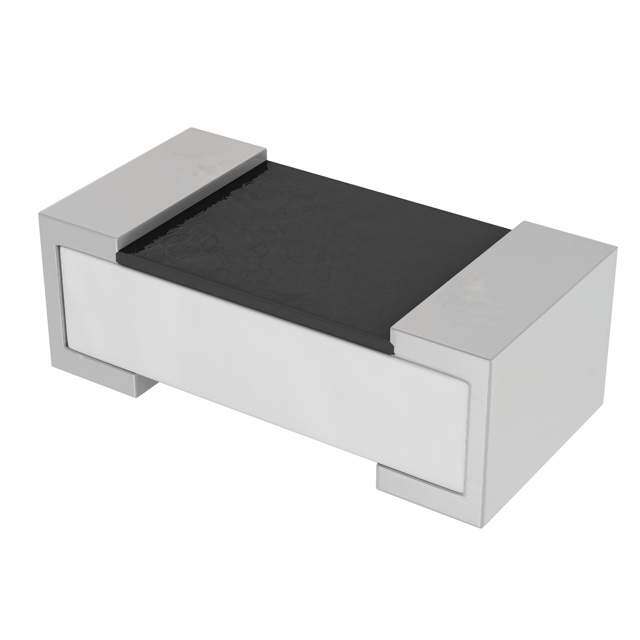
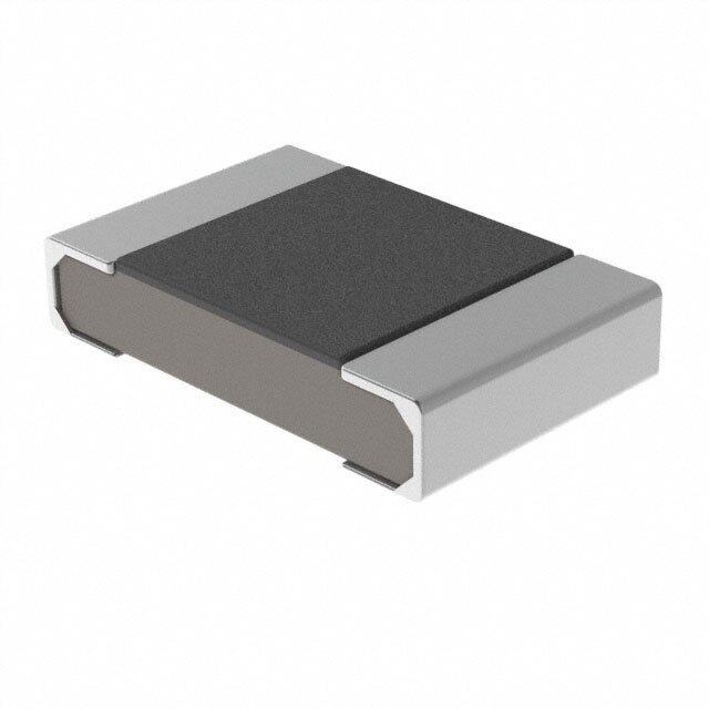
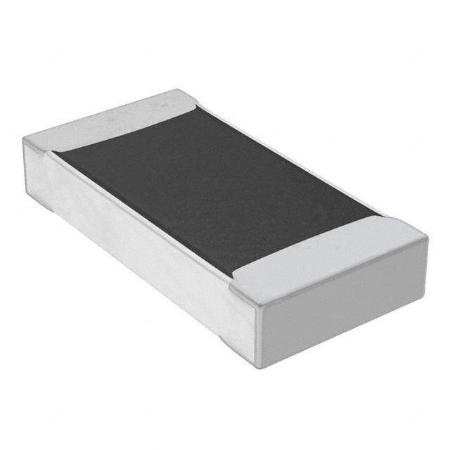
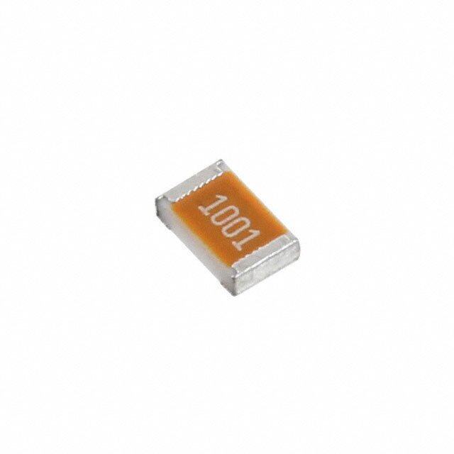
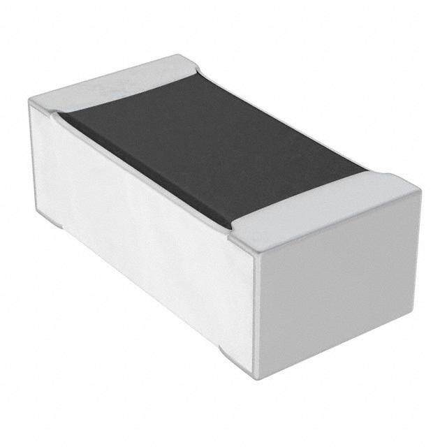
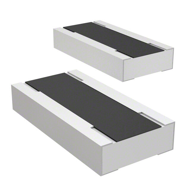
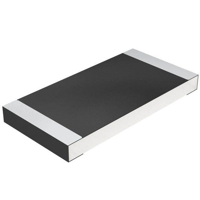
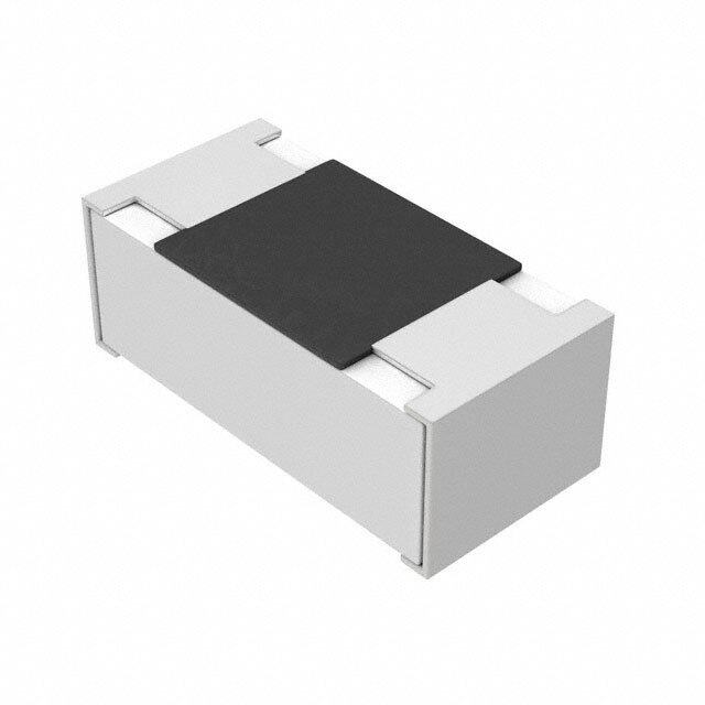
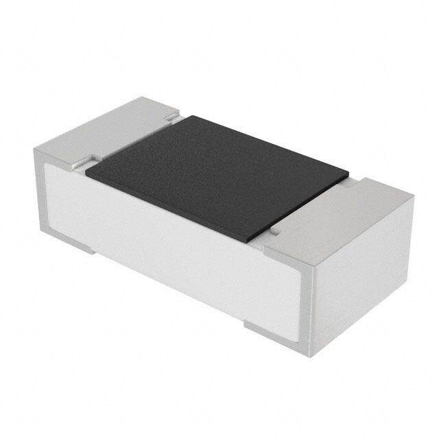
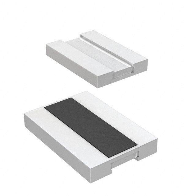
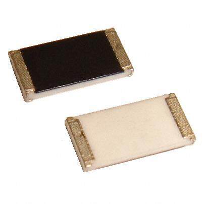
ICGOO电子元器件商城为您提供AC0402FR-0712K1L由YAGEO AMERICA CORPORATION设计生产,在icgoo商城现货销售,并且可以通过原厂、代理商等渠道进行代购。 AC0402FR-0712K1L价格参考¥0.01-¥0.01。YAGEO AMERICA CORPORATIONAC0402FR-0712K1L封装/规格:芯片电阻 - 表面安装, 12.1 kOhms ±1% 0.063W,1/16W 厚膜 芯片电阻 0402(1005 公制) 汽车级 AEC-Q200,防潮 厚膜。您可以下载AC0402FR-0712K1L参考资料、Datasheet数据手册功能说明书,资料中有AC0402FR-0712K1L 详细功能的应用电路图电压和使用方法及教程。
Yageo品牌的AC0402FR-0712K1L是一款0402封装尺寸的表面贴装薄膜电阻,阻值为12.1kΩ,精度±1%,适用于对精度和稳定性要求较高的电子电路。该电阻广泛应用于消费电子、通信设备、工业控制、车载电子以及医疗设备等领域,尤其适合需要空间紧凑设计和高性能表现的场景。
| 参数 | 数值 |
| 品牌 | Yageo |
| 产品目录 | 无源元件 |
| 描述 | 厚膜电阻器 - SMD 1/16W 12.1K ohm 1% |
| 产品分类 | |
| 产品手册 | |
| 产品图片 |
|
| rohs | RoHS 合规性豁免 |
| 产品系列 | 薄膜电阻器,厚膜电阻器 - SMD,Yageo AC0402FR-0712K1L |
| 产品型号 | AC0402FR-0712K1L |
| 产品 | Thick Film Resistors SMD |
| 产品种类 | 厚膜电阻器 - SMD |
| 功率额定值 | 62.5 mW (1/16 W) |
| 商标 | Yageo |
| 外壳代码-in | 0402 |
| 外壳代码-mm | 1005 |
| 外壳宽度 | 0.5 mm |
| 外壳长度 | 1 mm |
| 外壳高度 | 0.32 mm |
| 容差 | 1 % |
| 封装 | Reel |
| 封装/箱体 | 0402 (1005 metric) |
| 工作温度范围 | - 55 C to + 155 C |
| 温度系数 | 100 PPM / C |
| 电压额定值 | 50 V |
| 电阻 | 12.1 kOhms |
| 类型 | Chip Resistor Surface Mount |
| 系列 | AC |


- 商务部:美国ITC正式对集成电路等产品启动337调查
- 曝三星4nm工艺存在良率问题 高通将骁龙8 Gen1或转产台积电
- 太阳诱电将投资9.5亿元在常州建新厂生产MLCC 预计2023年完工
- 英特尔发布欧洲新工厂建设计划 深化IDM 2.0 战略
- 台积电先进制程称霸业界 有大客户加持明年业绩稳了
- 达到5530亿美元!SIA预计今年全球半导体销售额将创下新高
- 英特尔拟将自动驾驶子公司Mobileye上市 估值或超500亿美元
- 三星加码芯片和SET,合并消费电子和移动部门,撤换高东真等 CEO
- 三星电子宣布重大人事变动 还合并消费电子和移动部门
- 海关总署:前11个月进口集成电路产品价值2.52万亿元 增长14.8%

PDF Datasheet 数据手册内容提取
DATA SHEET THICK FILM CHIP RESISTORS AUTOMOTIVE GRADE AC series ±5%, ±1%, ±0.5% Sizes 0201/0402/0603/0805/1206/ 1210/1218/2010/2512 RoHS compliant & Halogen free 6 V. 7 1 0 2 0, 2 e n u J – n o ti a c cifi e p s t c u d o r P
Product specification 2 Chip Resistor Surface Mount AC SERIES 0201 to 2512 12 SCOPE ORDERING INFO RMATION - GLOBAL PART NUMBER This specification describes AC0201 Part number is identified by the series name, size, tolerance, packaging to AC2512 chip resistors with lead- type, temperature coefficient, taping reel and resistance value. free terminatio ns made by thick film GLOBAL PART NUMBER process. AC XXXX X X X XX XXXX L (1) (2) (3) (4) (5) (6) (7) APPLICATIONS All general purpose applications (1) SIZE Car electronics, industrial 0201/ 0402 / 0603 / 0805 / 1206 / 1210 / 1218 / 2010 / 2512 application (2) TOLERANCE FEATURES D = ±0.5% AEC-Q200 qualified F = ±1% Moisture sensitivity level: MSL 1 J = ±5% (for Jumper ordering, use code of J) AC series soldering is compliant (3) PACKAGING TYPE with J-STD-020D R = Paper taping reel K = Embossed taping reel Halogen free epoxy RoHS compliant (4) TEMPERATURE COEFFICIENT OF RESISTANCE - Products with lead-free – = Base on spec terminations meet RoHS requirements (5) TAPING REEL - Pb-glass contained in electrodes, resistor element and glass are 07 = 7 inch dia. Reel 10 = 10 inch dia. Reel exempted by RoHS 13 = 13 inch dia. Reel 7W = 7 inch dia. Reel & 2 x standard power Reduce environmentally hazardous waste (6) RESISTANCE VALUE High component and equipment 1Ω to 22 MΩ reliability There are 2~4 digits indicated the resistance value. Letter R/K/M is decimal point, no The resistors are 100% performed need to mention the last zero after R/K/M, e.g.1K2, not 1K20. by automatic optical inspection Detailed coding rules of resistance are shown in the table of “Resistance rule of prior to taping. global part number”. (7) DEFAULT CODE Letter L is the system default code for ordering only. (Note) Resistance rule of global part ORDERING EXAMPLE number The ordering code for an AC0402 Resistance coding Example chip resistor, value 100 KΩ with rule ±1% tolerance, supplied in 7-inch 1R = 1Ω tape reel is: AC0402FR-07100KL. XRXX 1R5 = 1.5Ω (1 to 9.76Ω) NOTE 9R76 = 9.76Ω 1. All our R-Chip products are RoHS XXRX 10R = 10Ω compliant and Halogen free. "LFP" of the (10 to 97.6Ω) 97R6 = 97.6Ω internal 2D reel label states "Lead-Free XXXR 100R = 100Ω Process". (100 to 976Ω) 976R = 976Ω 2. On customized label, "LFP" or specific XKXX 1K = 1,000Ω symbol can be printed. (1 to 9.76 KΩ) 9K76 = 9760Ω 3. AC series with ±0.5% tolerance is also available. For further information, please XMXX 1M = 1,000,000Ω contact sales. (1 to 9.76 MΩ) 9M76= 9,760,000Ω XXMX 10M = 10,000,000Ω (10 MΩ) www.yageo.com Jun. 20, 2017 V.6
Product specification 3 Chip Resistor Surface Mount AC SERIES 0201 to 2512 12 MARKING AC0201 / AC0402 No marking Fig. 1 AC0603 / AC0805 / AC1206 / AC1210 / AC2010 / AC2512 03 E-24 series: 3 digits, ±5% First two digits for significant figure and 3rd digit for number of zeros Fig. 2 Value= 10 KΩ AC 0603 0 E-24 series: 3 digits, ±1% & ±0.5% One short bar under marking letter Fig. 3 Value = 24 Ω E-96 series: 3 digits, ±1% & ±0.5% First two digits for E-96 marking rule and 3rd letter for number of zeros Fig. 4 Value = 12.4 KΩ AC0805 / AC12 06 / AC1210 / AC2010 / AC2512 Both E-24 and E-96 series: 4 digits, ±1% & ±0.5% First three digits for significant figure and 4th digit for number of zeros Fig. 5 Value = 10 KΩ A C1218 E-24 series: 3 digits, ±5% First two digits for significant figure and 3rd digit for number of zeros Fig. 6 Value = 10 KΩ 00 Both E-24 and E-96 series: 4 digits, ±1% & ±0.5% First three digits for significant figure and 4th digit for number of zeros Fig. 7 Value = 10 KΩ N O TE F or further marking information, please refer to data sheet “Chip resistors marking”. Marking of AC series is the same as RC series. www.yageo.com Jun. 20, 2017 V.6
Product specification 4 Chip Resistor Surface Mount AC SERIES 0201 to 2512 12 C ONSTRUCTION The resistors are constructed on top of an automotive grade ceramic body. Internal metal electrodes are added at each end and connected by a resistive glaze. The resistive glaze is covered by a protective glass. The compositio n of the glaze is adjusted to give the approximately required resistance value and laser trimming of this resistive glaze a chieves the value within tolerance. The whole element is covered by a protective overcoat. Size 0603 and bigger is marked with the resistance value on top. Finally, the two external terminations (Ni / matte tin) are added, as shown in Fig.8. OOUUTTLLIINNEESS markinglayer markinglayer overcoat overcoat protectiveglass protectiveglass resistivelayer resistivelayer (Jumperchipisaconductor) (Jumperchipisaconductor) innerelectrode innerelectrode termination(Ni/mattetin) termination(Ni/matte tin) innerelectrode innerelectrode YNSC088 ceramicsubstrate YNSC088_1 ceramicsubstrate Fig. 8_1 Chip resistor outlines Fig. 8_2 AC2010/ 2512 double power chip resistor outlines D IM ENSIONS T able 1 For outlines, please refer to Fig. 9 TY P E L (mm) W (mm) H (mm) I (mm) I (mm) 1 2 AC0 201 0.60±0.03 0.30±0.03 0.23±0.03 0.12±0.05 0.15±0.05 AC0402 1.00 ±0.05 0.50 ±0.05 0.32 ±0.05 0.20 ±0.10 0.25 ±0.10 AC0603 1.60 ±0.10 0.80 ±0.10 0.45 ±0.10 0.25 ±0.15 0.25 ±0.15 AC0805 2.00 ±0.10 1.25 ±0.10 0.50 ±0.10 0.35 ±0.20 0.35 ±0.20 AC1206 3.10 ±0.10 1.60 ±0.10 0.55 ±0.10 0.45 ±0.20 0.40 ±0.20 AC1210 3.10 ±0.10 2.60 ±0.15 0.55 ±0.10 0.45 ±0.15 0.50 ±0.20 AC1218 3.10 ±0.10 4.60 ±0.10 0.55 ±0.10 0.45 ±0.20 0.40 ±0.20 AC2010 5.00 ±0.10 2.50 ±0.15 0.55 ±0.10 0.55 ±0.15 0.50 ±0.20 AC2512 6.35 ±0.10 3.10 ±0.15 0.55 ±0.10 0.60 ±0.20 0.50 ±0.20 For dimension, please refer to Table 1 AC0201/0402 0603/0805/1206/1210/ AC1218 Side view for all type 2010/2512 Fig. 9 Chip resistor dimensions www.yageo.com Jun. 20, 2017 V.6
Product specification 5 Chip Resistor Surface Mount AC SERIES 0201 to 2512 12 E LECTRICAL CHARACTERISTICS Table 2 CHARACTERISTICS Operating Max. Max. Dielectric Resistance Temperature Jumper TYPE POW ER Temperature Working Overload Withstanding Range Coefficient Criteria Range Voltage Voltage Voltage 5% (E24) 1Ω ≤ R ≤ 10Ω Rated Current 1Ω ≤ R ≤ 10MΩ -100/+350ppm℃ 0.5A 1% (E24/E96) 10Ω < R ≤ 10M Maximum –55 °C to AC0201 1/20 W 25V 50V 50V 1Ω ≤ R ≤ 10MΩ ±200ppm℃ Current 155 °C 0.5% (E24/E96) 1.0A 10Ω ≤ R ≤ 1MΩ Jumper<50mΩ 5% (E24) 1Ω ≤ R ≤ 10Ω Rated Current 1Ω ≤ R ≤ 22MΩ ±200ppm°C 1A –55 °C to 0.5%, 1% (E24/E96) 10Ω < R ≤ 10MΩ Maximum 1/16 W 50V 100V 100V 155 °C 1Ω ≤ R ≤ 10MΩ ±100ppm°C Current Jumper<50mΩ 10MΩ < R ≤ 22MΩ 2A AC0402 ±200ppm°C 5% (E24) 1Ω ≤ R ≤ 10Ω –55 °C to 1Ω ≤ R ≤ 10MΩ ±200 ppm°C 1/8W 50V 100V 100V 155 °C 0.5%, 1% (E24/E96) 10Ω < R ≤ 10MΩ 1Ω ≤ R ≤ 10MΩ ±100 ppm°C 5% (E24) 1Ω ≤ R ≤ 10Ω Rated Current 1Ω ≤ R ≤ 22MΩ ±200ppm°C 1A –55 °C to 0.5%, 1% (E24/E96) 10Ω < R ≤ 10MΩ Maximum 1/10 W 75V 150V 150V 155 °C 1Ω ≤ R ≤ 10MΩ ±100ppm°C Current Jumper<50mΩ 10MΩ < R ≤ 22MΩ 2A AC0603 ±200ppm°C 5% (E24) 1Ω ≤ R ≤ 10Ω –55 °C to 1Ω ≤ R ≤ 10MΩ ±200 ppm°C 1/5 W 75V 150V 150V 155 °C 0.5%, 1% (E24/E96) 10Ω < R ≤ 10MΩ 1Ω ≤ R ≤ 10MΩ ±100 ppm°C www.yageo.com Jun. 20, 2017 V.6
Product specification 6 Chip Resistor Surface Mount AC SERIES 0201 to 2512 12 CHARACTERISTICS Operating Max. Max. Dielectric Resistance Temperature Jumper TYPE POWER Temperature Working Overload Withstanding Range Coefficient Criteria Range Voltage Voltage Voltage 5% (E24) 1Ω ≤ R ≤ 10Ω Rated Current 1Ω ≤ R ≤ 22 MΩ ±200ppm°C 2A –55 °C to 0.5%, 1% (E24/E96) 10Ω < R ≤ 10MΩ Maximum 1/8 W 150V 300V 300V 155 °C 1Ω ≤ R ≤ 10MΩ ±100ppm°C Current Jumper < 50mΩ 10MΩ < R ≤ 22MΩ 5A AC0805 ±200ppm°C 5% (E24) 1Ω ≤ R ≤ 10Ω –55 °C to 1Ω ≤ R ≤ 10MΩ ±200 ppm°C 1/4 W 150V 300V 300V 155 °C 0.5%, 1% (E24/E96) 10Ω < R ≤ 10MΩ 1Ω ≤ R ≤ 10MΩ ±100 ppm°C 5% (E24) 1Ω ≤ R ≤ 10Ω Rated Current 1Ω ≤ R ≤ 22MΩ ±200ppm°C 2A –55 °C to 0.5%, 1% (E24/E96) 10Ω < R ≤ 10MΩ Maximum 1/4 W 200V 400V 500V 155 °C 1Ω ≤ R ≤ 10MΩ ±100ppm°C Current Jumper<50mΩ 10MΩ < R ≤ 22MΩ 10A AC1206 ±200ppm°C 5% (E24) 1Ω ≤ R ≤ 10Ω –55 °C to 1Ω ≤ R ≤ 10MΩ ±200 ppm°C 1/2 W 200V 400V 500V 155 °C 0.5%, 1% (E24/E96) 10Ω < R ≤ 10MΩ 1Ω ≤ R ≤ 10MΩ ±100 ppm°C 5% (E24) 1Ω ≤ R ≤ 10Ω Rated Current 1Ω ≤ R ≤ 22MΩ ±200ppm°C 2A –55 °C to 0.5%, 1% (E24/E96) 10Ω < R ≤ 10MΩ Maximum 1/2 W 200V 500V 500V 155 °C 1Ω ≤ R ≤ 10MΩ ±100ppm°C Current Jumper<50mΩ 10MΩ < R ≤ 22MΩ 10A AC1210 ±200ppm°C 5% (E24) 1Ω ≤ R ≤ 10Ω –55 °C to 1Ω ≤ R ≤ 10MΩ ±200 ppm°C 1 W 200V 500V 500V 155 °C 0.5%, 1% (E24/E96) 10Ω < R ≤ 10MΩ 1Ω ≤ R ≤ 10MΩ ±100 ppm°C www.yageo.com Jun. 20, 2017 V.6
Product specification 7 Chip Resistor Surface Mount AC SERIES 0201 to 2512 12 CHARACTERISTICS Operating Max. Max. Dielectric Resistance Temperature Jumper TYPE POWER Temperature Working Overload Withstanding Range Coefficient Criteria Range Voltage Voltage Voltage 5% (E24) 1Ω ≤ R ≤ 10Ω Rated Current 1Ω ≤ R ≤ 1MΩ ±200ppm°C 6A –55 °C to 1 W 200V 500V 500V 0.5%, 1% (E24/E96) 10Ω < R ≤ 1MΩ Maximum 155 °C 1Ω ≤ R ≤ 1MΩ ±100ppm°C Current AC1218 Jumper<50mΩ 10A 5% (E24) 1Ω ≤ R ≤ 10Ω –55 °C to 1Ω ≤ R ≤ 1MΩ ±200 ppm°C 1.5W 200V 500V 500V 155 °C 0.5%, 1% (E24/E96) 10Ω < R ≤ 1MΩ 1Ω ≤ R ≤ 1MΩ ±100 ppm°C 5% (E24) 1Ω ≤ R ≤ 10Ω Rated Current 1Ω ≤ R ≤ 22MΩ ±200ppm°C 2A –55 °C to 0.5%, 1% (E24/E96) 10Ω < R ≤ 10MΩ Maximum 3/4 W 200V 500V 500V 155 °C 1Ω ≤ R ≤ 10MΩ ±100ppm°C Current Jumper<50mΩ 10MΩ < R ≤ 22MΩ 10A AC2010 ±200ppm°C 5% (E24) 1Ω ≤ R ≤ 10Ω –55 °C to 1Ω ≤ R ≤ 10MΩ ±200 ppm°C 1.25W 200V 500V 500V 155 °C 0.5%, 1% (E24/E96) 10Ω < R ≤ 10MΩ 1Ω ≤ R ≤ 10MΩ ±100 ppm°C 5% (E24) 1Ω ≤ R ≤ 10Ω Rated Current 1Ω ≤ R ≤ 22MΩ ±200ppm°C 2A –55 °C to 0.5%, 1% (E24/E96) 10Ω < R ≤ 10MΩ Maximum 1 W 200V 500V 500V 155 °C 1Ω ≤ R ≤ 10MΩ ±100ppm°C Current Jumper<50mΩ 10MΩ < R ≤ 22MΩ 10A AC2512 ±200ppm°C 5% (E24) 1Ω ≤ R ≤ 10Ω –55 °C to 1Ω ≤ R ≤ 10MΩ ±200 ppm°C 2 W 200V 400V 500V 155 °C 0.5%, 1% (E24/E96) 10Ω < R ≤ 10MΩ 1Ω ≤ R ≤ 10MΩ ±100 ppm°C www.yageo.com Jun. 20, 2017 V.6
Product specification 8 Chip Resistor Surface Mount AC SERIES 0201 to 2512 12 FOOTPRINT AND SOLDERING PROFILES Recommended footprint and soldering profiles of AC-series is the same as RC-series. Please refer to data sheet “Chip resistors mounting”. PACKING ST YLE AND PACKAGING QUANTITY Table 3 Packing style and packaging quantity PA CKING STYLE REEL AC0201 AC0402 AC0603 AC0805 AC1206 AC1210 AC1218 AC2010 AC2512 DIMENSION Paper taping reel (R) 7" (178 mm) 10,000 10,000 5,000 5,000 5,000 5,000 --- --- --- 10" (254 mm) 20,000 20,000 10,000 10,000 10,000 10,000 --- --- --- 13" (330 mm) 50,000 50,000 20,000 20,000 20,000 20,000 --- --- --- Embossed taping reel (K) 7" (178 mm) --- --- --- --- --- --- 4,000 4,000 4,000 TEMPERATURE COEFFICIENT OF RESISTANCE N OTE RESISTANCE 1. For papRerA/eNmbGoEss ed tape and reel specifications/dimensions, please refer to data sheet “Chip resistors packing”. PT040 100 mΩ to 910 mΩ 2 FUNCTIONAL DESCRIPTIO±N20 0 ppm/°C OPOTPP0EE6RR0AATTIINNGG TTEEMMPPEERRAATTUURREE RRAANNGGEE ±200 ppm/°C R3 ange: –55 °C to +155 °C PPPTOO0WW80EERR RRAATTIINNGG ±200 ppm/°C E5a ch type rated power at 70 °C: 100 MΩ TO 910 MΩ AC0201=1/20W (0.05W) PT120 AC0402=1/16W (0.0625W); 110/08 mWΩ (0.125W) > 100 mΩ 6 AC0603=1/10W (0.1W); 1/5W (0.2W) APTC2008105=1/8W (0.125W); 1/4 W(0.25 W) ±100 ppm/°C ±75 ppm/°C A0 C1206=1/4W (0.25W); 1/2 W (0.5 W) AC1210=1/2W (0.5W); 1W PT251 AC1218=1W; 1.5W ±100 ppm/°C ±75 ppm/°C 2 AC2010=3/4W (0.75W); 1.25W AC2512=1 W; 2W RATED VOLTAGE Fig. 10 Masa ax ifmunucmti odnis soipf athtieo no p(Pemr aatxin) gin a mpebriceennt ttaegme poef rraattuerde p(Tower) amb The DC or AC (rms) continuous working voltage corresponding to the rated power is determined by the following formula: V = (PxR) Or Maximum working voltage whichever is less Where V = Continuous rated DC or AC (rms) working voltage (V) P = Rated power (W) R = Resistance value (Ω) www.yageo.com Jun. 20, 2017 V.6
Product specification 9 Chip Resistor Surface Mount AC SERIES 0201 to 2512 12 TESTS AND REQUIREMENTS Table 4 Test condition, procedure and requirements TE ST TEST METHOD PROCEDURE REQUIREMENTS High Temperat ure AEC-Q200 Test 3 1,000 hours at TA = 155 °C, unpowered ±(1.0%+0.05Ω) for D/F tol Exposure MIL-STD-202 Method 108 ±(2.0%+0.05Ω) for J tol <50 mΩ for Jumper Moisture AEC-Q200 Test 6 Each temperature / humidity cycle is defined at ±(0.5%+0.05Ω) for D/F tol Resistance MIL-STD-202 Method 106 8 hours (method 106F), 3 cycles / 24 hours for ±(2.0%+0.05Ω) for J tol 10d. with 25 °C / 65 °C 95% R.H, without steps <100 mΩ for Jumper 7a & 7b, unpowered Biased AEC-Q200 Test 7 1,000 hours; 85 °C / 85% RH ±(1.0%+0.05Ω) for D/F tol Humidity MIL-STD-202 Method 103 10% of operating power ±(3.0%+0.05Ω) for J tol Measurement at 24±4 hours after test conclusion. <100 mΩ for Jumper Operational Life AEC-Q200 Test 8 1,000 hours at 125 °C, derated voltage applied for ±(1.0%+0.05Ω) for D/F tol MIL-STD-202 Method 108 1.5 hours on, 0.5 hour off, still-air required ±(3.0%+0.05Ω) for J tol <100 mΩ for Jumper Resistance to AEC-Q200 Test 15 Condition B, no pre-heat of samples ±(0.5%+0.05Ω) for D/F tol Soldering Heat MIL-STD-202 Method 210 Lead-free solder, 260±5 °C, 10±1 seconds ±(1.0%+0.05Ω) for J tol immersion time <50 mΩ for Jumper Procedure 2 for SMD: devices fluxed and No visible damage cleaned with isopropanol Thermal Shock AEC-Q200 Test 16 -55/+125 °C ±(0.5%+0.05Ω) for D/F tol MIL-STD-202 Method 107 Number of cycles is 300. Devices mounted ±(1.0%+0.05Ω) for J tol Maximum transfer time is 20 seconds. <50 mΩ for Jumper Dwell time is 15 minutes. Air – Air ESD AEC-Q200 Test 17 Human Body Model, ±(3.0%+0.05 Ω) AEC-Q200-002 1 pos. + 1 neg. discharges <50 mΩ for Jumper 0201: 500V 0402/0603: 1KV 0805 and above: 2KV www.yageo.com Jun. 20, 2017 V.6
Product specification 10 Chip Resistor Surface Mount AC SERIES 0201 to 2512 12 TEST TEST METHOD PROCEDUR E REQUIREMENTS Solderability AEC-Q200 Test 18 Electrical Test not required Magnification 50X - Wetting Well tinned (≥95% covered) J-STD-002 SMD conditions: No visible damage (a) Method B, aging 4 hours at 155 °C dry heat, dipping at 235±3 °C for 5±0.5 seconds. (b) Method B, steam aging 8 hours, dipping at 215±3 °C for 5±0.5 seconds. (c) Method D, steam aging 8 hours, dipping at 260±3 °C for 7±0.5 seconds. Board Flex AEC-Q200 Test 21 Chips mounted on a 90mm glass epoxy resin ±(1.0%+0.05Ω) AEC-Q200-005 PCB (FR4) <50 mΩ for Jumper Bending for 0201/0402: 5 mm 0603/0805: 3 mm 1206 and above: 2 mm Holding time: minimum 60 seconds Temperature MIL-STD-202 Method 304 At +25/–55 °C and +25/+125 °C Refer to table 2 Coefficient of Resistance (T.C.R.) Formula: R2–R1 T.C.R= ------------------------- ×106 (ppm/°C) R (t –t ) 1 2 1 Where t =+25 °C or specified room temperature 1 t =–55 ° C or +125 °C test temperature 2 R =resistance at reference temperature in ohms 1 R =resistance at test temperature in ohms 2 Short Time IEC60115-1 4.13 2.5 times of rated voltage or maximum ±(1.0%+0.05Ω) for D/F tol Overload overload voltage whichever is less for 5 sec ±(2.0%+0.05Ω) for J tol at room temperature <50 mΩ for Jumper FOS ASTM-B-809-95 Sulfur (saturated vapor) 500 hours, 60±2℃, ±( 1.0%+0.05Ω) unpowered www.yageo.com Jun. 20, 2017 V.6
Product specification 11 Chip Resistor Surface Mount AC SERIES 0201 to 2512 12 REVISION HISTORY REVISION DATE CHANGE NOTIFICATION DESCRIPTION Version 6 May 31, 2017 - - Add 10" packing Version 5 Dec. 07, 2015 - - Add in AC double power Version 4 May 25, 2015 - - Remove 7D packing - Extend resistance range - Add in AC0201 - Update FOS test and requirements Version 3 Feb 13, 2014 - - Feature description updated - add ±0.5% - delete 10" taping reel Version 2 Feb. 10, 2012 - - Jumper criteria added - AC1218 marking and outline figure updated Version 1 Feb. 01, 2011 - - Case size 1210, 1218, 2010, 2512 extended - Test method and procedure updated - Packing style of 7D added Version 0 Nov. 10, 2010 - - First issue of this specification www.yageo.com Jun. 20, 2017 V.6
Product specification 12 Chip Resistor Surface Mount AC SERIES 0201 to 2512 12 LEGAL DISCLAIMER Yageo, its distributors and agents (collectively, “Yageo”), hereby disclaims any and all liabilities for any errors, inaccuracies or incompleteness contained in any product related information, including but not limited to product speci fications, datasheets, pictures and/or graphics. Yageo may make changes, modifications and/or improvement s to product related information at any time and without notice. Yageo makes no representation, warranty, and/or guarantee about the fitness of its products for any particular purpose or the continuing production of any of its products. To the maximum extent permitted by law, Yageo disclaims (i) any and all liability arising out of the application or use of any Yageo product, (ii) any and all liability, including without limitation special, consequential or incidental damages, and (iii) any and all implied warranties, including warranties of fitness for a particular purpose, non-infringement and merchantability. Yageo statements regarding the suitability of products for certain types of applications are based on Yageo’s knowledge of typical operating conditions for such types of applications in a generic nature. Such statements are neither binding statements of Yageo nor intended to constitute any warranty concerning the suitability for a specific customer application or use. They are intended for use only by customers with requisite knowledge and experience for determining whether Yageo products are the correct products for their application or use. In addition, unpredicatable and isolated cases of product failure may still occur, therefore, customer application or use of Yageo products which requires higher degree of reliability or safety, shall employ additional protective safeguard measures to ensure that product failure would not result in personal injury or property damage. Yageo products are not designed for application or use in medical, life-saving, or life-sustaining devices or for any other application or use in which the failure of Yageo products could result in personal injury or death. Customers using or selling Yageo products not expressly indicated for above-mentioned purposes shall do so at their own risk and agree to fully indemnify Yageo and hold Yageo harmless. Information provided here is intended to indicate product specifications only. Yageo reserves all the rights for revising this content without further notification, as long as products are unchanged. Any product change will be announced by PCN. www.yageo.com Jun. 20, 2017 V.6