ICGOO在线商城 > 连接器,互连器件 > D-Sub,D 形连接器 - 后壳,罩 > 980-2000-346

 Datasheet下载
- 型号: 980-2000-346
- 制造商: ITT CANNON
- 库位|库存: xxxx|xxxx
- 要求:
| 数量阶梯 | 香港交货 | 国内含税 |
| +xxxx | $xxxx | ¥xxxx |
查看当月历史价格
查看今年历史价格
980-2000-346产品简介:
ICGOO电子元器件商城为您提供980-2000-346由ITT CANNON设计生产,在icgoo商城现货销售,并且可以通过原厂、代理商等渠道进行代购。 980-2000-346价格参考¥24.77-¥31.29。ITT CANNON980-2000-346封装/规格:D-Sub,D 形连接器 - 后壳,罩, Position Connector 。您可以下载980-2000-346参考资料、Datasheet数据手册功能说明书,资料中有980-2000-346 详细功能的应用电路图电压和使用方法及教程。
品牌为ITT Cannon, LLC、分类为D-Sub,D形连接器 - 后壳,罩,型号为980-2000-346的产品,主要用于电子设备和工业系统中对D型连接器提供机械保护和电磁屏蔽。该后壳或罩通常应用于通信设备、计算机外设、自动化控制系统以及航空航天等高可靠性领域,确保连接器在恶劣环境中保持稳定性能。
| 参数 | 数值 |
| 产品目录 | |
| 描述 | DSUB 15 METAL DIECAST B/S |
| 产品分类 | |
| 品牌 | ITT Cannon |
| 数据手册 | |
| 产品图片 | |
| 产品型号 | 980-2000-346 |
| rohs | 无铅 / 符合限制有害物质指令(RoHS)规范要求 |
| 产品系列 | * |
| 标准包装 | 1 |


- 商务部:美国ITC正式对集成电路等产品启动337调查
- 曝三星4nm工艺存在良率问题 高通将骁龙8 Gen1或转产台积电
- 太阳诱电将投资9.5亿元在常州建新厂生产MLCC 预计2023年完工
- 英特尔发布欧洲新工厂建设计划 深化IDM 2.0 战略
- 台积电先进制程称霸业界 有大客户加持明年业绩稳了
- 达到5530亿美元!SIA预计今年全球半导体销售额将创下新高
- 英特尔拟将自动驾驶子公司Mobileye上市 估值或超500亿美元
- 三星加码芯片和SET,合并消费电子和移动部门,撤换高东真等 CEO
- 三星电子宣布重大人事变动 还合并消费电子和移动部门
- 海关总署:前11个月进口集成电路产品价值2.52万亿元 增长14.8%

PDF Datasheet 数据手册内容提取
D sub:Layout 1 3/24/09 12:37 PM Page 1
Inside front cvr & TOC:Layout 1 3/24/09 11:55 AM Page 1 Cannon, VEAM, BIW A Historical Achievement of Technology Leadership Defining and Championing Innovation Showcasing a portfolio of creativity, ITTʼs “Engineered For Life” execution embraces products which have be- come ubiquitous in a broad collection of markets including: Military/Aerospace, CivilAircraft, Industrial Instru- mentation, Medical, Oil & Gas, Energy,Transportation,Telecom/Handset, Computer, Consumer, and Automotive. ITTʼs rich interconnect history embraces contributions to both technological breakthroughs and social move- ments. With one of the industryʼs broadest product offerings, ITTʼs interconnect products have supported: • Every Free World space mission, bringing the universe to our doorstep. • Motion picture, radio, and television equipment, serving laughter and entertainment to millions. • Commercial and military communications systems, linking the voices of the world. • Computerized tools, reshaping the information highway. • Aircraft, rapid transit, and automobiles, mobilizing our expanding society. • Oil and natural gas production, powering the worldʼs economies. • Agricultural equipment, attacking the roots of world hunger. First Cannonpioneers Cannoncreates Cannonoriginates Cannondevelops Cannonestablishes “CannonPlug” soundandfilm Cannoncreates “AN”military thefirst“D-Sub” thefirst“Micro” anaviationmilestone +2000 4PolePower connectorswith “K”series plugs connectors connectors throughtheexpansion Connector theMSeries connectorsfor ofRackandPanel DC-1’s Cannondevelops Cannonpioneers Cannonpartners connectorswiththe thefirst guidedmissle withtechnology BKAD/ESeries Thefirstcommercialandpowerconnectors Thefirstaviation Tri-Service umbilical leaderstodevelop Breakaway circular&rack connector,the connectors thefirstcomplete 1980 Cannonconnectorsmadepossiblethefirst panelconnectors motherofmodern fiberoptic Technology radiomicrophones,thefirstblackandwhite developedby daymilitary systems Leadership televisioncamerasaswellasthefirst Cannon spec’s Chip-on-Flex colortelevisionequipment. Lean Cannon’sAF Cannon’s 1970 manufacturing Firewallconnectors Xconnectoristhe PHD usedinearly firstmicrominiature Internetdeployed DC-3transports audioconnector 1960 systems Cannon foundedby JamesCannon 1950 Pioneering Quadrax technologies 1940 Cannon’sfirstentry intotheMedical Engineered 1930 Electronicsmarket solutions 1915 1920 PhotocourtesyofTheAcademyof Stacking MotionPictures,ArtsandSciences. The Power,Film, Aviation Military Telecom Space Medical, Growth Charting Beginning Commercial Transportation theFuture www.ittcannon.com
NEW TOC:Layout 1 3/26/09 10:34 AM Page 1 Cannon D Subminiature Accessories Table of Contents Description DSubminiatureAccessories Accessory Selection Guide.................................2-3 • Metal Backshell DieCastZinc,EMIShieldedStraightExit....................4 MetalBackshellStraightExit .............................5 MetalBackshell45°Exit................................15 Clamps ............................................7-8 • Plastic Backshell Snap-TogetherMetalizedPlastic,EMIShielded ...............9 LockingHardwareforSnap-TogetherPlasticBackshell.........10 LowCostMetalizedPlastic,StraightExit...................10 Snap-TogetherUniversal................................11 One-PieceSnap-Together...............................11 One-PieceStraightExit.................................12 One-PiecePlastic,90°Exit ..............................12 • Locking Hardware ScrewLockAssemblies..............................13-14 SlideLockAssemblies..................................15 SpringLatchAssemblies................................16 Jackscrew/JackpotAssemblies ...........................17 • Guide Pin Plate FemaleGuidePinPlate.................................18 MaleGuidePinPlate ..................................19 • Connector Saver HighReliabilityConnectorSaver .........................20 • Miscellaneous PolarizingPlates......................................21 RightAngleBrackets ..................................21 WireHoleFillers......................................21 DustCap ...........................................22 InterfacialSeal.......................................22 PottingShell.........................................22 Part Number Index.........................................23 Product Safety Warranty ...................................25 www.ittcannon.com
D sub:Layout 1 3/24/09 12:37 PM Page 2 D Cannon D-Subminiature Accessories Selection Guide LockingHardware SlidingLock FemaleScrewLock MaleScrewLock Retainer SlideLockPost SpringLatchPlate SpringLatch Backshell Style seepage14 seepage13 seepage15 seepage15 seepage16 seepage16 EMIShielded Snap-Together MetalizedPlastic StraightExit — — — — — — seepage9 EMIShielded Snap-Together MetalizedPlastic 50ºExit — — — — — — seepage9 EMIShielded DieCastZinc Metal — (cid:2) — — — — seepage4 Metal MetalBackshell 45ºExit — — — — — — seepage4 Metal DeepStraight Clamp • • • • • • seepage7 Metal RoundCable Clamp • • • • • • seepage7 Metal ShortStraight Clamp • • • • • • seepage8 Metal 90ºEntry • • • • • • seepage8 Plastic Snap-Together Universal • • — — — — seepage11 Plastic One-Piece Snap-Together — (cid:2) — — — — seepage11 Plastic One-PiecePlastic StraightExit — — • • • • seepage12 Plastic One-PiecePlastic 90ºExit — — • • • • seepage12 (cid:2)Suppliedwithbackshell • Optionalcompatiblelockinghardware —Notcompatible Dimensionsshowninmm(inch) Specificationsanddimensionssubjecttochange www.ittcannon.com 2
D sub:Layout 1 3/24/09 12:37 PM Page 3 D Cannon D-Subminiature Accessories Selection Guide LockingHardware Jackpostfor JackscrewAssembly JackpostAssembly RecessedJackscrew ExtendedJackscrew Thumbscrew In-LineConnections seepage17 seepage17 seepage10 seepage10 seepage10 seepage10 — — • • • • — — • • • • — — — — — — — — — — — — — • — — — — — • — — — — — • — — — — — — — — — — — — — — — — — — — — — — — — — — — — — — — — — — Dimensionsshowninmm(inch) Specificationsanddimensionssubjecttochange www.ittcannon.com 3
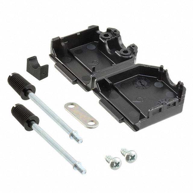
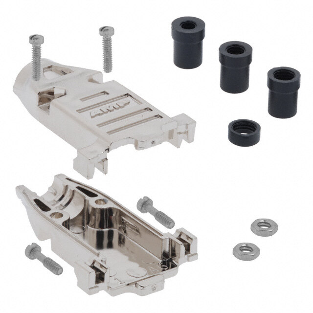
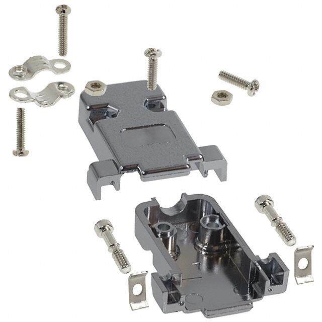
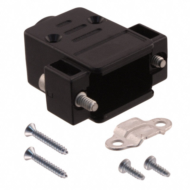
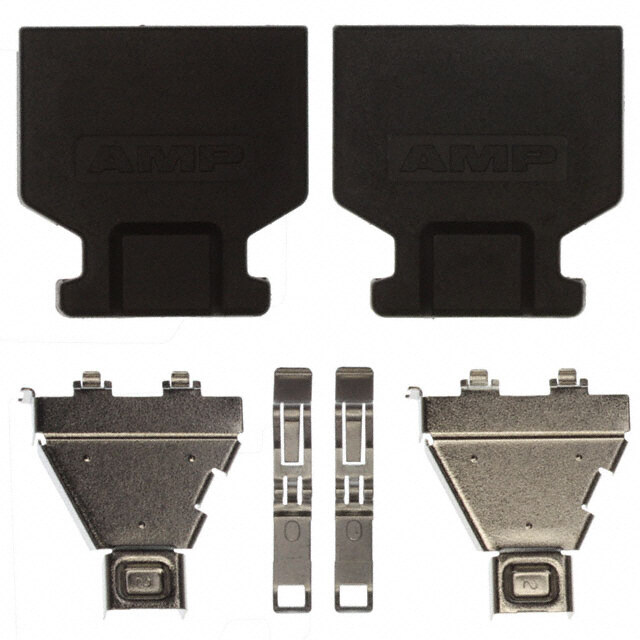
D sub:Layout 1 3/24/09 12:37 PM Page 4 D Cannon D-Subminiature Accessories Metal Backshell Die Cast Zinc Backshell, Straight Exit, EMI Shielded 9and15 25 37and50 Position Position Position C C B B B A D A D A D EDia. EDia. EDia. F F F DiecastmetalbackshellsreduceEMI/RFIemis- Shell Part A B C D øE F sions.Diecastmetalbackshellsofferimproved Size Layout Number ±0,13(.005) ±0,13(.005) ±0,13(.005) ±0,13(.005) ±0,13(.005) ±0,13(.005) shieldinginaruggedpackage. DE 9 980-2000-345 31,12(1.225) 37,21(1.465) 15,75(.620) 15,75(.620) 10,16(.400) 24,99(.984) DA 15 980-2000-346 39,12(1.540) 40,64(1.600) 15,75(.620) 15,75(.620) 10,16(.400) 33,32(1.312) DB 25 980-2000-347 53,09(2.090) 39,37(1.550) 17,53(690) 15,75(.620) 13,34(.525) 47,17(1.857) ProductFeatures DC 37 980-2000-348 69,34(2.730) 45,72(1.800) 21,95(.864) 15,75(.620) 18,44(.726) 63,50(2.500) • ImprovesconformancetoFCCDOC DD 50 980-2000-349 66,70(2.626) 45,72(1.800) 21,95(.864) 18,54(.730) 18,44(.726) 61,11(2.406) #20780shieldingrequirements • Nocrimpferruletoolingneeded Specifications MaterialsandFinishes • Kit consistsof1frontshell,1rearshell, Attenuation: -50dB@1000MHz BackshellMaterial: Zinc 2screws,2hexnuts,2mountingscrews, TemperatureRange: -20ºCto80ºC BackshellFinish: ClearZinc 2endbrackets,1setofcompression inserts CompressionInserts: PVC HardwareMaterial: Steel HardwareFinish: ClearZinc Attenuation DiecastShellShieldingPerformance 0 -10 -20 -30 db -40 -50 -60 -70 100 1000 Mhz Compressioninserts(includedwithdiecastzincmetalbackshell) Compressioninsertsaccommodateawidevariety 9and15Position* 25Position* 37 and 50Position* ofcablesizes. 1 Position CableDiameter 1 2 6 2 3 5 3 9,15 4,83/8,89 (.190/.350) 3 5 4 2 25 4,83/11,68 (.190/.460) 1 4 4 37,50 7,62/17,27(.300/.680) 5 *Insertsmaybesuppliedmirrorimage. #1 #2 #3 #4 #5 #6 Position O.D. I.D. O.D. I.D. O.D. I.D. O.D. I.D. O.D. I.D. O.D. I.D. 9,15 12,07(.475) 8,13(.320) 9,14(.360) 8,00(.315) 9,14(.360) 6,48(.255) 9,14(.360) 7,24(.285) 9,14(.360) 5,33(.210) — — 25 15,24(.600) 11,43(.450) 11,43(.450) 10,41(.410) 11.43(.450) 9,40(.370) 11.43(.450) 7,62(.300) 11.43(.450) 5,84(.230) — — 37.50 16,64(.655) 14,48(.570) 17,78(.700) 15,75(.620) 20,57(.810) 16,51(.650) 16,64(.655) 12,70(.500) 16,64(.655) 10,80(.425) 16,64(.655) 8,89(.350) Dimensionsshowninmm(inch) Specificationsanddimensionssubjecttochange www.ittcannon.com 4
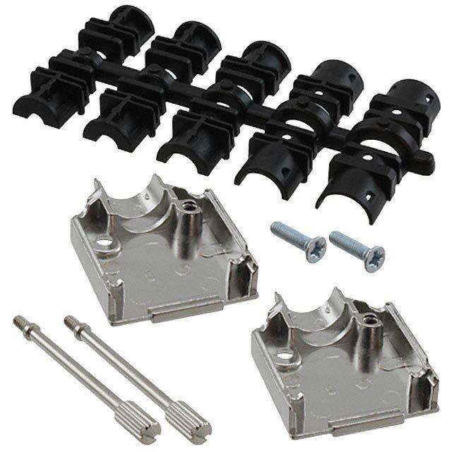
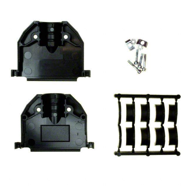
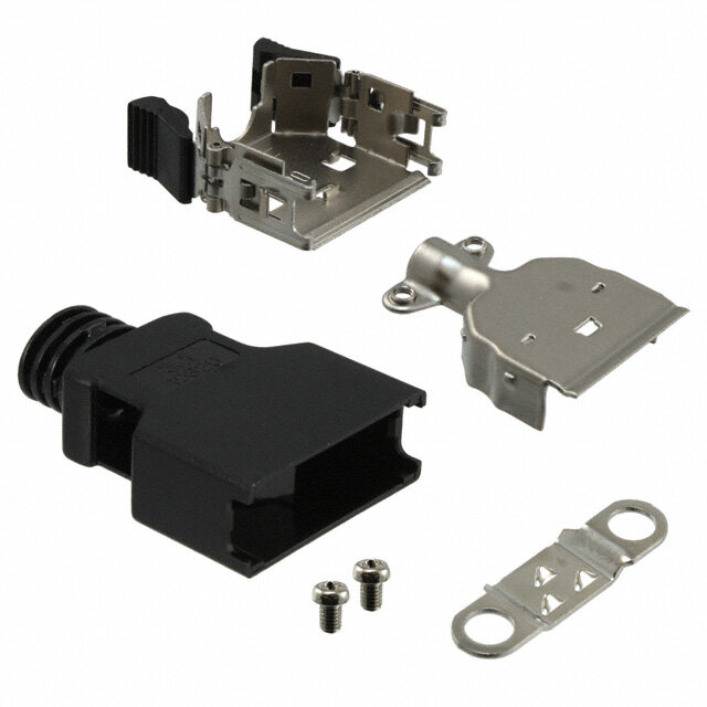
D sub:Layout 1 3/26/09 7:52 AM Page 5 D Cannon D-Subminiature Accessories Metal Backshell Metal Backshell Straight Exit ThenewCannonMetalBackshellsD*FMseries forD-SubminiatureConnectorsoffersprotectionfrom magneticandradiointerferencestocableassemblies. Thisbackshellseriesischaracterizedbysimpleassemblyandfitfor ndustrialandtelecomapplications. PPrroodduucctt FFeeaattuurreess:: • No crimp ferrule tooling needed • Material: Zinc, blue chromated SSiizzee 1155 • Unique metal filled plastic cable strain relief guarantees 360° shielding • RoHS compliant • -40 - +120°C temperature range • Corrosion resistant Part Description Part Description With #4-40 UNC With M3 Shell A B C D Cable Jackscew Jackscrew Size Diameter DEFME-101 DEFMX-101 Size 9 39,55mm [1.555inch] 31,3mm [1.232inch] 14,6mm [0.575inch] 25,0mm [0.984inch] 4 - 9mm DAFME-101 DAFMX-101 Size 15 41,7mm [1.642inch] 39,3mm [1.547inch] 14,6mm [0.575inch] 33,3mm [1.311inch] 4 - 9mm DBFME-101 DBFMX-101 Size 25 49,0mm [1.929inch] 53,5mm [2.106inch] 14,6mm [0.575inch] 47,0mm [1.850inch] 4 - 9mm DCFME-101 DCFMX-101 Size 37 53,3mm [1.098inch] 69,7mm [2.744inch] 14,6mm [0.575inch] 63,5mm [2.500inch] 4 - 9mm Kit consists of 1 front shell, 1 rear shell, 4 strain reliefs, 2 mounting crosshead screws, and 2 jack screws. AAsssseemmbbllyy iinnssttrruuccttiioonnss SSiizzee 99,, 1155,, 2255,, 3377 AAtttteennuuaattiioonn ccuurrvvee Use two halves of strain relief Strip cable 18mm and shape Attach the strain relief around (different sizes can be mixed) cable to two pigtails the cable Bend cable shielding back on Mount connector and cable into Assemble the other half outside of strain relief the backshell (screwing force: 100-120 Ncm) Dimensionsshowninmm(inch) Specificationsanddimensionssubjecttochange www.ittcannon.com 5
D sub:Layout 1 4/1/09 10:23 AM Page 6 D Cannon D-Subminiature Accessories Metal Backshell Metal Backshell 45° Exit ThenewCannonMetalBackshellsD*FMseries forD-SubminiatureConnectorsoffersprotectionfrom magneticandradiointerferencestocableassemblies. ThisbackshellseriesischaracterizedbysimpleassemblyandfitforIndustrialandtelecomapplications. PPrroodduucctt FFeeaattuurreess:: SSiizzee 1155 • No crimp ferrule tooling needed • Material: Zinc, blue chromated • Unique metal filled plastic cable strain relief guarantees 360° shielding • RoHS compliant • -40 - +120°C temperature range • Corrosion resistant SSiizzee 5500 Part Description Part Description With #4-40 UNC With M3 Shell A B C D Cable Jackscew Jackscrew Size Diameter DEFME-100 DEFMX-100 Size 9* 37,5mm [1.476inch] 35,5mm [1.398inch] 14,6mm [0.575inch] 4 - 9mm DAFME-100 DAFMX-100 Size 15** 41,5mm [1.634inch] 39,5mm [1.555inch] 14,6mm [0.575inch] 33,3mm [1.311inch] 4 - 9mm DBFME-100 DBFMX-100 Size 25** 41,5mm [1.634inch] 53,5mm [2.106inch] 14,5mm [0.571inch] 47,0mm [1.850inch] 4 - 9mm DCFME-100 DCFMX-100 Size 37** 41,5mm [1.634inch] 70,0mm [2.756inch] 14,5mm [0.571inch] 63,5mm [2.500inch] 4 - 9mm DDFME-100 DDFMX-100 Size 50*** 45,0mm [1.772inch] 67,5mm [2.657inch] 17,4mm [0.69inch] 61,0mm [2.402inch] 13-16mm *Size 9 Backshell: Kit consists of 1 front shell, 1 rear shell, 4 strain reliefs, 2 mounting crosshead screws, 1 jack screw **Size 15, 25, 37 Backshell: Kit consists of 1 front shell, 1 rear shell, 4 strain reliefs, 2 mounting crosshead screws, 2 jack screws ***Size 50 Backshell: Kit consists of 1 front shell, 1 rear shell, 1 cable clamp, 4 mounting crosshead screws, 2 jack screws AAsssseemmbbllyy iinnssttrruuccttiioonnss SSiizzee 99,, 1155,, 2255,, 3377 AAtttteennuuaattiioonn ccuurrvvee Use two halves of strain relief Strip cable 18mm and shape Attach the strain relief around (different sizes can be mixed) cable to two pigtails the cable Bend cable shielding back on Mount connector and cable into Assemble the other half outside of strain relief the backshell (screwing force: 100-120 Ncm) Dimensionsshowninmm(inch) Specificationsanddimensionssubjecttochange www.ittcannon.com 6
D sub:Layout 1 3/24/09 12:37 PM Page 7 D Cannon D-Subminiature Accessories Metal Backshell Metal Backshell Metal Backshells provide strain relief. Materials and Finishes Various profiles available for different cable rout- ing requirements. Backshell Material: Low Carbon Steel or Brass Backshell Finish: Chromate over Cadmium (Mil Spec) or Zinc (RoHS) Product Features Hardware Material: Steel Qualified to MIL-Spec M85049 Deep Straight Clamp E CABLE ENTRY B IN SHELL H MAX. F G 0,38 ± 0,13 (.015 ± .005) C A D MAX. CABLE ENTRY 3,45 ± 0,13 IN SHELL (.136 ± .005) TWO MTG. HOLES Mil-Spec Parts (Brass) Brass Shell RoHS Compliant Mil-Spec 50 µ in. Gold Size Part Number Part Number Part Number over Copper DE DE24657-29 M85049/48-1-6F DE24657-5 DE24657-16 •Kit consists of 1 shell, 2 cable clamps, DA DA24658-28 M85049/48-1-7F DA24658-2 DA24658-15 2 screws, 2 hex nuts. DB DB24659-27 M85049/48-1-8F DB24659-2 DB24659-15 DC DC24660-27 M85049/48-1-9F DC24660-11 DC24660-16 DD DD24661-27 M85049/48-1-10F DD24661-4 DD24661-13 Shell Part Mil Spec A B C D E F G H Size Layout Number Part Number* ±0,38 (.015) ±0,572 (.0225) ±0,38 (.015) max. ±0,38 (.015) ±0,38 (.015) ±0,38 (.015) max. DE 9 DE24657 M85049/48-1-1F 30,56 (1.203) 12,484 (.4915) 24,99 (.984) 14,68 (.578) 9,53 (.375) 9,53 (.375) 19,05 (.750) 31,75 (1.250) DA 15 DA24658 M85049/48-1-2F 38,89 (1.531) 12,484 (.4915) 33,32 (1.312) 14,68 (.578) 18,11 (.713) 7.93 (.312) 19,05 (.750) 31,75 (1.250) DB 25 DB24659 M85049/48-1-3F 52,78 (2.078) 12,484 (.4915) 47,04 (1.852) 14,68 (.578) 25,40 (1.000) 7.93 (.312) 25,40 (1.000) 39,70 (1.563) DC 37 DC24660 M85049/48-1-4F 69,04 (2.718) 12,484 (.4915) 63,50 (2.500) 14,68 (.578) 34,93 (1.375) 7.93 (.312) 25,40 (1.000) 39,70 (1.563) DD 50 DD24661 M85049/48-1-5F 66,68 (2.625) 15,253 (.6005) 61,11 (2.406) 17,45 (.578) 35,71 (1.406) 10,31 (.406) 28,57 (1.125) 42,88 (1.688) * Parts ordered with no suffix or “Z” suffix will be substituted with “F” suffix. Round Cable Clamp A 3,05 ± ,013 C (.120 ± .005) DIA. G E TWO MTG. HOLES F D MAX. B + + CABLE ENTRY 0,38 ± 0,13 (.015 ± .005) •Kit consists of 1 shell, 2 cable clamps, Mil-Spec Parts (Brass) Brass 2 screws, 2 hex nuts. Shell RoHS Compliant Mil-Spec 50 µ in. Gold Size Part Number Part Number Part Number over Copper DE DE44994-14 M85049/48-2-6F DE44994-3 DE44994-2 DA DA20961-26 M85049/48-2-7F DA20961-3 DA20961-16 DB DB20962-30 M85049/48-2-8F DB20962-8 DB20962-18 DC DC20963-27 M85049/48-2-9F DC20963-8 DC20963-17 DD DD20964-32 M85049/48-2-10F DD20964-8 DD20964-19 Shell Part Mil Spec A B C D E F G Size Layout Number Part Number* ±0,38 (.015) ±0,572 (.0225) ±0,38 (.015) max. ±0,38 (.015) ±0,38 (.015) ±0,76 (.030) DE 9 DE44994 M85049/48-2-1F 30,68 (1.208) 12,70 (.500) 24,99 (.984) 10,31 (.406) 16,79 (.661) 3,18 (.125) 26,18 (1.031) DA 15 DA20961 M85049/48-2-2F 38,89 (1.531) 12,70 (.500) 33,33 (1.312) 10,31 (.406) 24,99 (.984) 3,18 (.125) 26,18 (1.031) DB 25 DB20962 M85049/48-2-3F 52,78 (2.078) 12,70 (.500) 47,04 (1.852) 15,06 (.593) 38,48 (1.515) 4,75 (.187) 26,98 (1.062) DC 37 DC20963 M85049/48-2-4F 69,04 (2.718) 12,70 (.500) 63,50 (2.500) 18,23 (.718) 55,14 (2.171) 6,35 (.250) 26,98 (1.062) DD 50 DD20964 M85049/48-2-5F 66,68 (2.625) 15,47 (.609) 61,11 (2.406) 20,62 (.812) 53,16 (2.093) 7,92 (.312) 26,98 (1.062) * Parts ordered with no suffix or “Z” suffix will be substituted with “F” suffix. Dimensions shown in mm (inch) Specifications and dimensions subject to change www.ittcannon.com 7
D sub:Layout 1 3/24/09 12:37 PM Page 8 D Cannon D-Subminiature Accessories Metal Backshell Short Straight Clamp A C B G 12,30 ± 0,38 (.484 ± .015) 3,05 ± 0,13 (.120 ± .005) DIA. F TWO MTG. HOLES (TYP.) E •Kit consists of 1 shell, 2 or 3 screws, CABLE 0,38 ± 0,13 ENTRY (.015 ± .005) 2 or 3 hex nuts Mil-Spec Parts (Brass) Brass Shell RoHS Compliant Mil-Spec 50 µ in. Gold Size Part Number Part Number Part Number over Copper DA DA19678-212 M85049/48-3-7F DA19678-38 DA19678-167 DB DB19678-213 M85049/48-3-8F DB19678-53 DA19678-168 DC DC19678-214 M85049/48-3-9F DC19678-85 DA19678-138 DD DD19678-214 M85049/48-3-10F DD19678-55 DA19678-161 No. of Shell Part Mil Spec Cable Locking A B C E F G Size Layout Number Part Number* Screws Included ±0,38 (.015) ±0,38 (.015) ±0,13 (.005) ±0,38 (.015) ±0,38 (.015) ±0,98 (.035) DA 15 DA19678-1 M85049/48-3-2F 2 38,88 (1.531) 12,70 (.500) 33,33 (1.312) 7,51 (.296) 7.93 (.312) 16,36 (.644) DB 25 DB19678-2 M85049/48-3-3F 2 52,78 (2.078) 12,70 (.500)) 47,04 (1.852) 7,51 (.296) 20,22 (.796) 16,36 (.644) DC 37 DC19678-3 M85049/48-3-4F 3 69,04 (2.718) 12,70 (.500) 63,50 (2.500) 7,51 (.296) 17,45 (.687) 16,36 (.644) DD 50 DD19678-4 M85049/48-3-5F 3 66,68 (2.625) 15,47 (.690) 61,11 (2.406) 9,91 (.390) 17,45 (.687) 17,63 (.694) * Parts ordered with no suffix or “Z” suffix will be substituted with “F” suffix. 90º Entry #4-40 E NC-2BTHD. CABLE ENTRY TWO MTG. HOLES A 2,77 ± 0,25 B (.109 ± .010) F CABLE G ENTRY C H •Kit consists of 1 shell, 1 cable clamp, 1 screw, 1 nut, 2 rivnuts (assembled) Mil-Spec Parts (Brass) Brass Shell RoHS Compliant Mil-Spec 50 µ in. Gold Size Part Number Part Number Part Number over Copper DE DE19977-72 M85049/50-6F DE19977-20 DE19977-47 DA DA19977-68 M85049/50-7F DA19977-6 DE19977-40 DB DB19977-69 M85049/50-8F DB19977-17 DE19977-43 DC DC19977-70 M85049/50-9F DC19977-18 DE19977-45 DD DC19977-71 M85049/50-10F DD19977-19 DE19977-44 Shell Part Mil Spec A B C E F G H Size Layout Number Part Number* ±0,38 (.015) ±0,38 (.015) ±0,13 (.005) ±0,38 (.015) ±0,38 (.015) ±0,98 (.035) DE 9 DE19977-5 M85049/50-1F 30,56 (1.203) 18,24 (.718) 24,99 (.984) 11,10 (.437) 11,10 (.437) 11,89 (.468) 7,14 (.281) DA 15 DA19977-1 M85049/50-2F 38,89 (1.531) 12,70 (.500) 33,33 (1.312) 11,10 (.437) 11,10 (.437) 11,89 (.468) 7,14 (.281) DB 25 DB19977-2 M85049/50-3F 52,78 (2.078) 12,70 (.500)) 47,04 (1.852) 11,10 (.437) 15,88 (.625) 11,89 (.468) 7,14 (.281) DC 37 DC19977-3 M85049/50-4F 69,04 (2.718) 12,70 (.500) 63,50 (2.500) 11,10 (.437) 20,63 (.812) 11,89 (.468) 7,14 (.281) DD 50 DD19977-4 M85049/50-5F 66,68 (2.625) 15,47 (.690) 61,11 (2.406) 14,28 (.562) 23,01 (.906) 13,47 (.531) 8,71 (.343) * Parts ordered with no suffix or “Z” suffix will be substituted with “F” suffix. Dimensions shown in mm (inch) Specifications and dimensions subject to change www.ittcannon.com 8
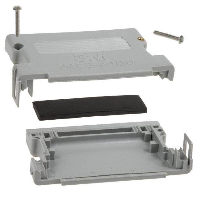
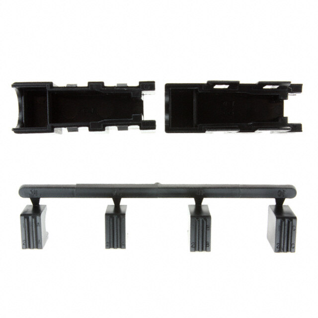
D sub:Layout 1 3/26/09 7:52 AM Page 9 D Cannon D-Subminiature Accessories Plastic Backshell Snap-Together Metalized Plastic Metalized plastic backshells reduce EMI/RFI emis- sions. Metalized plastic provides a light weight solu- CABLE CLAMP CABLE tion. Includes integral strain relieving cable clamp. GROUNDING TANG Product Features • Improves conformance to FCC DOC #20780 shielding requirements • No crimp ferrule tooling needed • Quick and simple assembly using snap- together design feature • Non-metalized, non-shielded versions available AAtttteennuuaattiioonn CCuurrvvee Note: Cable grounding tang not available on DE size backshell. dB Specifications Materials and Finishes Attenuation: -49 dB @ 100MHz Material: Thermoplastic, UL 94V-0 rated Temperature Range: -20º C to 80º C Finish: Nickel over Copper kHz MHz MHz MHz Straight Exit C D ØH MAX • Kit consists of 1 front shell, 1 rear shell, 1 cable clamp, 2 screws E • Optional locking hardware 16,99±0,30 sold separately, see page 10 (.669±.012) A B Shell Comptuer Cable Ribbon Cable A B C D E øH Size Layout Shielded Non-Shielded Gray Non-Shielded Black Shielded Non-Shielded Gray ±0,15 (.006) ±0,30 (.012) ±0,30 (.012) ±0,30 (.120) ±0,20 (.008) Max. DE 9 DE121073-154 DE121073-159 DE121073-259 DE121073-164 DE121073-169 24,95 (.982) 30,81 (1.213) 23,70 (.933) 16,00 (.630) 35,99 (1.417) 7,32 (.288A DA 15 DA121073-150 DA121073-155 DA121073-255 DA121073-160 DA121073-165 33,30 (1.311) 39,09 (1.539) 31,80 (1.252) 16,00 (.630) 42,00 (1.654) 8,31 (.327) DB 25 DB121073-151 DB121073-156 DB121073-256 DB121073-161 DB121073-166 47,00 (1.850) 53,01 (2.087) 45,01 (1.772) 16,00 (.630) 42,00 (1.654) 10,52 (.414) DC 37 DC121073-152 DC121073-157 DC121073-257 DC121073-162 DC121073-167 63,45 (2.498) 69,29 (2.728) 60,30 (2.374) 16,00 (.630) 42,00 (1.654) 12,32 (.485 ) DD 50 DD121073-153 DD121073-158 DD121073-258 - - 61,10 (2.410) 66,90 (2.634) 58,30 (2.295) 19,00 (.748) 42,00 (1.654) 13,00 (.512) 50º Exit D E Shell Shielded Non-Shielded B C D E Cable Diameter Size Layout Part # Part # Gray ±0,30 (.012) ±0,30 (.012) ±0,30 (.012) ±0,20 (.008) Min. Max. DE 9 DE121073-54 DE121073-59 35,99 (1.417) 22,00 (8.66) 16,00 (.630) 35,99 (1.417) 3,51 (.138) 7,49 (.295) • Kit consists of 1 front shell, DA 15 DA121073-50 DA121073-55 44,29 (1.744) 27,31 (1.075) 16,00 (.630) 42,01 (1.654) 6,50 (.256) 8,99 (.354) 1 rear shell, 1 cable clamp, DB 25 DB121073-51 DB121073-56 57,99 (2.283) 41,00 (1.614) 16,00 (.630) 42,01 (1.654) 6,50 (.256) 11,00 (.433) 2 screws DC 37 DC121073-52 DC121073-57 74,50 (2.933) 57,51 (2.264) 16,00 (.630) 42,01 (1.654) 6,50 (.256) 11,00 (.433) DD 50 DD121073-53 DD121073-58 72,97 (2.873) 54.99 (2.165) 19,00 (.748) 42,01 (1.654) 8,99 (.354) 13,00 (.512) • Optional locking hardware sold separately, see page 5 Dimensions shown in mm (inch) Specifications and dimensions subject to change www.ittcannon.com 9
D sub:Layout 1 3/24/09 12:37 PM Page 10 D Cannon D-Subminiature Accessories Plastic Backshell Locking Hardware for Snap -Together Plastic Backshell Recessed Jackscrew Extended Jackscrew Thumbscrew 13,50 (.531) 19,00 (.748) 4,30 9,00 (.169) 9,00 50,00 (1.969) (.354) #4-40 (.354) #4-40 4,30 (.169) 9,00 (.354) Threads Threads 6,00 (.236) #4-40 (4.D1,I57A07.) (M6.2,I03N06.) (4.1,1601) (M6.2,I03N06.) THREADS DIA. Materials and Finishes Part Number Material Finish Quantity Required per Connector 250-8501-004 Brass Nickel 2 250-8501-009 (M3) ,250-8501-010 (#4-40) Brass Nickel 2 250-8501-013 Brass Nickel 2 Jackpost for In-Line Connections Jackpost Assembly Rectangular Nut Jackp ost 5,00 11,00 4,90 (.193) (.197) (.433) 6,00 3,00 (.118) (.236) MIN 5,00 4,60 (.197) (.189) 1,81 #4-40 UNC-2B (.075) #4-40 UNC-2B 5,00 6,00 #4-40 UNC-2A (.197) (.236) Assembly consists of 1 rectangular nut, (ACROSS FLATS) 1 jackpost, 1 # 4-40 lock washer. Part Number: D121073-19 Material: Brass Finish: Nickel Quantity required per connector: 2 Straight Exit - Metalized Plastic Low Cost C 50 POSITION IS MARKED “CANNON” ONLY F B ITT CANNON ØE D A Shell Part A B C D ø E F SizeLayout Number • Kit consists of 1 front shell, 1 rear shell, DE 9 980-2000-350 30,91 (1.217) 39,29 (1.547) 16,26 (.640) 16,26 (.640) 10,16 (.400) 24,99 (.984) 1 cable clamp, 2 screws DA 15 980-2000-351 39,24 (1.545) 38,23 (1.505) 16,26 (.640) 16,26 (.640) 10,16 (.400) 33,32 (1.312) DB 25 980-2000-352 53,09 (2.090) 42,04 (1.655) 18,03 (.710) 16,26 (.640) 13,26 (.522) 47,17 (1.857) DC 37 980-2000-353 69,44 (2.734) 46,48 (1.830) 23,01 (.906) 16,26 (.640) 18,44 (.726) 63,50 (2.500 ) DD 50 980-2000-354 67,18 (2.645) 47,12 (1.855) 23,88 (.940) 19,56 (.770) 18,44 (.726) 61,11 (2.406) Materials and Finishes: Thermoplastic, UL 94V-0 rated, Nickel plated Dimensions shown in mm (inch) Specifications and dimensions subject to change www.ittcannon.com 10
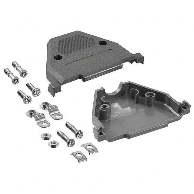
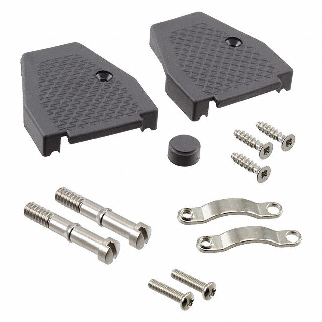
D sub:Layout 1 3/24/09 12:37 PM Page 11 D Cannon D-Subminiature Accessories Plastic Backshell Snap -Together Universal 42,50 B DIA. MAX. (1.673). CABLE ENTRY 39,50 C (1.555). D Shell Part øB C D Size Layout Number max. ±0,20 (.008) ±0,20 (.008) •2-piece snap-together design for quick DE 9 DE115339-20 7,01 (.276) 17,00 (.669) 19,51 (.768) assembly. DA 15 DA115339-21 9,60 (.378) 17,00 (.669) 27,79 (1.094) •Customer furnishes tie-wrap. DB 25 DB115339-22 11,61 (.457) 17,00 (.669) 41,61 (1.638) DC 37 DC115339-23 13,00 (.512) 17,00 (.669) 59,99 (2.283) DD 50 DD115339-24 16,00 (.630) 19,81 (.780) 52,32 (2.060) Note: Part Numbers above replace the following part number series: DE110963-1 to DD110963-5 Materials and Finishes Material: Black Thermoplastic, UL 94V-0 rated One-Piece Snap-Together A C 16,21 (.638) 48,00 E (1.890) CLAMP, THERMOPLASTIC ∅ D ITT CANNON CLAMP, METAL • Low cost • Easy to assemble Shell Part ø D • Mounting hardware included Size Layout Number A C max. E DE 9 DEBS-9 35,20 (1.386) 24,99 (.984) 5,69 (.224) 27,51 (1.083) • 2 thumbscrews, 2 cable clamps DA 15 DABS-15 43,31 (1.705) 33,33 (1.312) 5,69 (.224) 31,19 (1.228) DB 25 DBBS-25 57,20 (2.252) 47,04 (1.852) 6,50 (.256) 38,30 (1.508) Materials and Finishes DC 37 DCBS-37 72,00 (2.83) 62,00 (2.44) 7,80 (.307) 43,08 (1.69) Backshell Material: Polypropylene DD 50 DDBS-50 73,70 (2.90) 63,70 (2.50) 8,20 (.322) 48,04 (1.89) Hardware Material: Steel Hardware Finish: Black Nickel Dimensions shown in mm (inch) Specifications and dimensions subject to change www.ittcannon.com 11
D sub:Layout 1 3/24/09 12:37 PM Page 12 D Cannon D-Subminiature Accessories Plastic Backshell One-Piece Plastic Straight Exit B G Cable Entry F ø E C A Cable Entry Cable Entry • Kit consists of 1 shell, 1 cable clamp, 1 set screw • Mounting hardware included D TWO SCREWS 4-24 X 5/16 long • 2 screws #4-24 x 5/16 long self tapping SELF-TAPPING • Accommodates spring latches Materials and Finishes Shell Part A B C D øE F G Size Layout Number ±0,38 (.015) ±0,38 (.015) ±0,13 (.005)±0,38 (.015) ±0,25 (.010) ±0,25 (.010) ±0,25 (.010) Material: Black Thermoplastic, DE 9 DE51218 30,94 (1.218)25,40 (1.000) 24,99 (.984) 12,70 (.500) 7,14 (.281) — — UL 94V-0 rated DA 15 DA51210 39,27 (1.546)25,40 (1.000)33,33 (1.312)12,70 (.500) 9,14 (.360) — — Hardware Material: Steel DB 25 DB51212 53,16 (2.093)31,75 (1.250)47,04 (1.852)12,70 (.500) — 12,52 (.493) 9.15 (.360) Hardware Finish: Chromate over Zinc DC 37 DC51214 69,44 (2.734)38,10 (1.500)63,50 (2.500)12,70 (.500) — 17,63 (.694 ) 9.15 (.360) DD 50 DD51216 67,06 (2.640)38,10 (1.500)61,11 (2.406)15,47 (.690) — 18,64 (.734) 11,89 (.468) 90º Exit K Cable Entry A ø H Cable Entry J B • Kit consists of 1 shell, 1 cable clamp, 1 set screw C D • Mounting hardware included • 2 screws #4-24 x 5/16 long self tapping Materials and Finishes Shell Part A B C D øH J K Size Layout Number ±0,38 (.015) ±0,38 (.015) ±0,13 (.005)±0,38 (.015) ±0,25 (.010) ±0,25 (.010) ±0,25 (.010) Material: Black Thermoplastic, DE 9 DE51219 37,95 (1.494)25,40 (1.000) 24,99 (.984) 12,70 (.500) 7,14 (.281) — — UL 94V-0 rated DA 15 DA51211 46,28 (1.822)25,40 (1.000)33,33 (1.312)12,70 (.500) 9,14 (.360) — — Hardware Material: Steel DB 25 DB51213 60,15 (2.368)31,75 (1.250)47,04 (1.852)12,70 (.500) — 12,52 (.493) 9.15 (.360) Hardware Finish: Chromate over Zinc DC 37 DC51215 76,43 (3.009)38,10 (1.500)63,50 (2.500)12,70 (.500) — 17,63 (.694 ) 9.15 (.360) DD 50 DD51217 74,04 (2.915)38,10 (1.500)61,11 (2.406)15,47 (.690) — 18,64 (.734) 11,89 (.468) Dimensions shown in mm (inch) Specifications and dimensions subject to change www.ittcannon.com 12
D sub:Layout 1 3/26/09 7:52 AM Page 13 D Cannon D-Subminiature Accessories Locking Hardware Screw Lock Assemblies ITT offers the largest variety of locking and latching hardware. Refer to the accessories selection guide on pages 2-3 for use with Front Panel Mount Rear Panel Mount Cannon backshells. Product Features SCREW SCREW •Ensures positive mating D SUBMINATURE •Provides locking and latching for high D SUBMINATURE CLIP WITH CONNECTOR CLIP WITH vibration applications CONNECTOR THREAD PIN OR SOCKET THREAD PIN OR SOCKET NUT MOUNTING NUT PANEL WASHER WASHER MOUNTING PANEL LOCK D SUBMINATURE LOCK WASHER CONNECTOR WASHER HEX NUT PIN OR SOCKET HEX NUT Male Screw Lock A SCREW #4-40 UNC-2A THD B C •Kit consists of 1 screw and 1 clip CLIP GAP CLIP •Order 2 per connector •Similar to M24308/25-Style Materials and Finishes Material: Steel Finish: Trivalent Chromate over Zinc Shell each 2 each A B C RoHS Compliant RoHS Compliant Size P/N P/N ±0,38(.015) ±0,2 (.010) ±0,13 (.005) P/N each P/N 2 each DE, DA, DB, DC D20419 D20419-119 14,10 (.555) 6,35 (.250) 1,22 (.048) D20419-211 D20419-218 DE, DA, DB, DC D20419-18 D20419-121 14,10 (.555) 7,14 (.281) 1,70 (.067) D20419-212 D20419-219 DE, DA, DB, DC D20419-21 D20419-122 14,10 (.555) 7,14 (.281) 2,34 (.092) D20419-213 D20419-220 DE, DA, DB, DC D20419-104 D20419-216 14,10 (.555) 7,92 (.312) 2,34 (.092) D20419-214 D20419-221 DD D20420 D20420-097 16,66 (.656) 6,35 (.250) 1,22 (.048) D20420-157 D20420-163 DD D20420-13 D20420-099 16,66 (.656) 7,14 (.281) 1,70 (.067) D20420-158 D20420-164 DD D20420-15 D20420-100 16,66 (.656) 7,14 (.281) 2,34 (.092) D20420-159 D20420-165 DD D20420-86 D20420-162 16,66 (.656) 7,92 (.312) 2,34 (.092) D20420-160 D20420-166 Dimensions shown in mm (inch) Specifications and dimensions subject to change www.ittcannon.com 13
D sub:Layout 1 4/1/09 10:23 AM Page 14 D Cannon D-Subminiature Accessories Locking Hardware Female Screw Lock Front Panel Mount Rear Panel Mount 6,35 (.250) APPROX. #4-40 NC-2B THD. REMOVE ONE WASHER 4,78 ± 0,38 FOR EACH 0,76 (.030) (.188 ± .015) OF PANEL THICKNESS •Kit consists of 1 nut, 3 washer, 1 lock Hex across Flats WHEN REAR MOUNTING 1,52 (0.60) MAX. PANEL washer, 1 hex nut. 4,78 ± 0,38 A •Order 2 per connector. (.188 ± .015) REAR FLANGE (REF.) #4-40 NC-2A THD Material: Steel NOTE: (1) A 6 inch/pound (female) and 4 inch/pound (male) maximum torque during assembly is recommended on steel screw Finish: Chromate over Cadmium (Mil Spec) lock assemblies. (2) A third flat washer is supplied for front panel mounting of tab shell connectors. or Zinc (RoHS) Yellow Chromate Over Cadmium Chromate Over Zinc RoHS Compliant A Designed to be comparable to each Kit of 2 each Kit of 2 each Part Number ± 0,38 (.015) Mil Spec Part Number D20418-2 D20418-82 D20418-128 D20418-134 7,92 (.312) M24308/26-1F-Style D20418-50 D20418-131 - D20418-135 12,70 (.500) - D20418-39 D20418-83 D20418-129 D20418-136 15,88 (.625) M24308/26-2F-Style D20418-74 D20418-132 - D20418-137 19,05 (.750) - Screw Locks for Connectors with Integral Threaded Inserts 3,50 (.138) 5,00 (.197) HEX MIN (ACROSS FLATS) THD A THD B 3,50 (.138) 5,75 4,50 MIN (.226) (.177) Part Thread Type Number THD A THD B D121073-39 # 4-40 UNC-2B # 4-40 UNC-2A D112041 * # 4-40 UNC-2B # 4-40 UNC-2A D121073-42 M3 M3 * without lock washer • Kit consists of 1 jackpost, 1 lock washer. • Order 2 per connector. Loose Spacer Dim A Part Number: 253-0343-000 (D*M Style) 5.84 ±.08 (.230 ±.003) A Part Number: 253-0343-011 (D*MA Style) 9.40 ±.13 (.370 ±.005) . .111260 . .119822 Material: Aluminum Finish: Chromate over Cadmium Dimensions shown in mm (inch) Specifications and dimensions subject to change www.ittcannon.com 14
D sub:Layout 1 3/26/09 7:52 AM Page 15 D Cannon D-Subminiature Accessories Locking Hardware Slide Lock Assemblies ITT offers the largest variety of locking and #4-40 HEX. NUT latching hardware. Refer to the accessories selection guide on pages 2-3 for use with Cannon backshells. LOCK WASHER Product Features SLIDE LATCH • Ensures positive mating #4-40 FLAT SCREW WASHERS • Provides locking and latching for high #4-40 POST vibration applications LOCK WASHER HEX NUT Sliding Lock Retainer Assembly 2 SCREWS #4-40 NC-2A THREAD 2,84 (.112) 3,66 ± 0,38 (.144 ± .015) RETAINER SLIDING LOCK 2,36 (.093) A TRAVEL REF. C B • Kit consists of 1 sliding lock plate, 2 mounting screws, 2 lock washer, 2 hex nuts • Order 1 kit per connector Shell Part A B C Finish/ Size Layout Number ± 0,38 (.015) ± 0,38 (.015) ± 0,13 (.005) Descriptions Material Treatment DE 9 DE51224-1 35,05 (1.380) 12,70 (.500) 25,00 (.984) DA 15 DA51220-1 43,70 (1.720) 12,70 (.500) 33,32 (1.312) Sliding Lock DB 25 DB51221-1 57,40 (2.260) 12,70 (.500) 47,04 (1.852) Plate Stainless Steel Passivated DC 37 DC51222-1 73,86 (2.908) 12,70 (.500) 63,50 (2.500) Screw, DD 50 DD51223-1 71,47 (2.814) 15,47 (.609) 61,11 (2.406) Mounting Steel Trivalent Washer Lock Steel Chromate over Nut, Hex Steel Zinc Slide Lock Post Assemblies SPACER WASHER LOCK WASHER #4-40 HEX NUT 4,60 (.180)HEX • Consists of 1 post, 2 washers, 1 lock washer, and 1 hex nut.1 2,59 (.102) • Order 2 per connector.2 ± 0,13 (.005) 10,57 (.416) ± 0,25 (.010) Each1,2 Kit of 2 each NOTE: When rear-mounting connector to a 1/16” Part Number: D53018 D53018-11 Material: Steel, Finish: Chromate/Zinc panel, delete the second spacer washer. D53018-14 D53018-20 Material: Stainless Steel, Finish: Passivated Dimensions shown in mm (inch) Specifications and dimensions subject to change www.ittcannon.com 15
D sub:Layout 1 3/24/09 12:37 PM Page 16 D Cannon D-Subminiature Accessories Locking Hardware Spring Latch Assemblies ITT offers the largest variety of locking and Unlocked Locked latching hardware. Refer to the accessories selection guide on pages 2-3 for use with Cannon backshells. Product Features • Low Cost • Minimizes field connection time • Positive lock between connectors • Packaged 2 kits per bag Materials and Finishes Material: Stainless Steel Treatment: Passivated Spring Latch Plate Assembly #4-40 SCREW 15,37 ± 0,64 #4-40 THD. x 7,92 (.312) (.605 ± .025) LONG SCREW 2,41 (.095) - 1,52 (.060) A B LATCH PLATE #4-40 HEX. NUT CONNECTOR EITHER PIN OR SOCKET Shell Part A B Part Number Size Layout Number ± 0,38 (.015) ± 0,38 (.015) Kit of 2 each DE, DA, DB, DC 9,15, 25, 37 D110278 12,42 (.489) 14,35 (.565) D110278-4 DD 50 D110280 15,47 (.609) 17,09 (.673) D110280-3 LOCK WASHER #4-40 HEX NUT • Kit consists of 1 plate, 1 screw, 1 lock washer,1 hex nut. • Order 2 kits per connector. Spring Latch Assembly SPRING LATCH SC#R4E-4W0 15,57 ± 0,64 #4-40 THD. x 7,92 (.312) (.613 ± .025) LONG SCREW B A C SPRING LATCH 2,41 (.095) MOUNTING BRACKET 1,52 (.060) #4-40 HEX. NUT CONNECTOR EITHER PIN OR SOCKET Shell Part A B C Part Number Size Layout Number ± 0,38 (.015) ± 0,38 (.015) ± 0,51 (.020) Kit of 2 each DE, DA, DB, DC 9,15, 25, 37 D110277 12,42 (.489) 14,35 (.565) 18,59 (.732) D110277-2 DD 50 D110279 15,47 (.609) 17,09 (.673) 18,59 (.732) D110279-3 LOCK WASHER D110277-4 Rear panel mount version also available #4-40 HEX. NUT • Kit consists of 1 spring, 1 screw, 1 bracket, 1 lock washer, 1 hex nut. • Order 2 kits per connector. Front panel mounting. Dimensions shown in mm (inch) Specifications and dimensions subject to change www.ittcannon.com 16
D sub:Layout 1 3/24/09 12:37 PM Page 17 D Cannon D-Subminiature Accessories Locking Hardware Jackscrew/Jackpost Assemblies ITT offers the largest variety of locking and Jackscrew Assembly Jackpost Assembly latching hardware. Refer to the accessories selection guide on pages 2-3 for use with HEAD, JACKSCREW Cannon backshells. # 2-56 UNC THD # 4-40 UNC THD # 4-40 UNC-2B THD # 4-40 UNC-2A THD RETAINING COMPOUND WASHER, #4 LOCK Ø 3,05 (.120) #4 HEX NUT STUD, JACKSCREW FEMALE POST Ø 3,05 (.120) Jackscrew Assembly 0,89 (.035) ± 0,13 (.005) 5,59 (.220) DIA. MAX. 9,40 (.370) MAX. 1,73 (.068) MAX. 16,26 (.640) MAX. • Kit consists of 2 studs, 2 heads, 1 tube retaining compound (US only) 4,57 (.180) • Order one kit per connector MAX. 0,64 (.025) Part Number: D110550 #4-40 UNC ± 0,13 (.005) Materials and Finishes THREAD 5,59 (.220) DIA. MAX. Material: Stainless Steel Treatment: Passivated Jackpost Assembly 4,75 (.187) HEX (ACROSS FLATS) CONNECTOR #4-40 UNC THREAD ASSY 5,84 (.230) ± 0,13 (.005) 14,10 (.555) ± 0,13 (.005) 1,14 (.045) • Kit consists of 2 posts, 2 hex nuts, 2 lock washer ± 0,13 (.005) • Order one kit per connector 5,59 (.220) MIN. PANEL 3,18 (.125) MAX. PERFECT THD. LOCK WASHER HEX NUT Part Number: D110551 #4-40 UNC THREAD Materials and Finishes Material: Stainless Steel Treatment: Passivated NOTE: Jack post is not compatible with rear-panel mount connectors. Dimensions shown in mm (inch) Specifications and dimensions subject to change www.ittcannon.com 17
D sub:Layout 1 3/24/09 12:37 PM Page 18 D Cannon D-Subminiature Accessories Guide Pin Plate Guide Pin Plate Female 9,60 (.378) MAX A MOUNTING PANEL B E + F + + + G F • Useful in blind mate applications. + • Kit consists of 1 plate, 2 screws. 1,57 • Guide pin inserts for Size 8 cavities for 6,35 (.250) MAX. (.062) C 1,60 (.063) ± Combo D®connectors also available. Refer to SOLDER POT D 0,41 ± (.016) Combo D Catalog. EXTENSION 4D,0IA4. (M.1I5N9.) MOUNTING HOLE 4 PRLAADC.ES 2 PLACES #4.40 UNC-2B THREAD (SCREW SUPPORT) Plate and Hardware Material: Steel 2 PLACES Plate and Hardware Finish: Chromate over Zinc Shell Part A B C D E F G H J K Size Layout Number ±0,41 (.016) ±0,13 (.005) ±0,13 (.005) ±0,13 (.005) ±0,13 (.005) ±0,13 (.005) ±0,41 (.016) ±0,41 (.016) ±0,41 (.016) ±0,41 (.016) DE 9 DE111920 49,61 (1.953) 40,08 (1.578) 25,00 (.986) 18,65 (.734) 15,27 (.601) 9,52 (.375) 25,40 (1.000) 30,58 (1.204) 12,29 (.484) 6,15 (.242) DA 15 DA22214 57,96 (2.282) 48,41 (1.906) 33,32 (1.312) 22,81 (.898) 19,43 (.765) 9,52 (.375) 25,40 (1.000) 38,91 (1.532) 12,29 (.484) 6,15 (.242) DB 25 DB22254 71,63 (2.820) 62,13 (2.446) 47,04 (1.852) 29,67 (1.168) 26,29 (1.035) 9,52 (.375) 25,40 (1.000) 51,21 (2.016) 11,91 (.469) 5,94 (.234) DC 37 DC22071 88,11 (3.469) 78,59 (3.094) 63,50 (2.500) 37,90 (1.492) 34,52 (1.359) 9,52 (.375) 25,40 (1.000) 67,49 (2.657) 11,91 (.469) 5,94 (.234) DD 50 DD21961 85,72 (3.375) 76,20 (3.000) 61,11 (2.406) 36,50 (1.437) 33,32 (1.312) 11,10 (.437) 28,58 (1.125) 65,10 (2.563) 14,30 (.563) 7,16 (.282) Recommended Panel Cutout 4,22 ± 0,05 K RADIUS B (.166 ± .002) DIA. 2 PLACES E 3,66 ± 0,13 + (.144 ± .005) DIA. F 2 PLACES + + + F + D J H Dimensions shown in mm (inch) Specifications and dimensions subject to change www.ittcannon.com 18
D sub:Layout 1 3/24/09 12:37 PM Page 19 D Cannon D-Subminiature Accessories Guide Pin Plate Guide Pin Plate Male A 4,78 ± 0,30 (.188 ± 0.12) B 6,35 (.250) MAX C 3,66 ± 0,13 SOLDER POT (.144 ± .005) EXTENSION 1,57 (.062) D 2 PLACES MAX. ITT CANNON 4,01 (.158) 4,06 (.160) REF DIA. MAX. DIA MAX. F E • Useful in blind mate applications. 1,57 ± 0,13 • Kit consists of 1 plate, 2 sems screws, 2 rivets, (.062 ± .005) 2 guide pins, 2 washer 8,71 ± 0,38 C L • Guide pin inserts for Size 8 cavities for Combo 22,22 ± 0,76 (.343 ± .015) G D®connectors also available. Refer to Combo D (.875 ± .030) Catalog. 4,06 ± 0,25 (.160 ± .010) Plate and Hardware Material: Steel Plate and Hardware Finish: Chromate over Zinc Guide Pin Material: Stainless Steel Shell Part A B C D E F G H J K Size Layout Number ±0,41 (.016) ±0,13 (.005) ±0,13 (.005) ±0,13 (.005) ±0,13 (.005) ±0,13 (.005) ±0,41 (.016) ±0,41 (.016) ±0,41 (.016) ±0,41 (.016) DE 9 DE111919 49,61 (1.953) 40,08 (1.578) 33,91 (1.335) 18,65 (.734) 25,40 (1.000) 19,05 (.750) 25,00 (.984) 12,29 (.484) 30,58 (1.204) 6,15 (.242) DA 15 DA22213 57,96 (2.282) 48,41 (1.906) 42,24 (1.663) 22,81 (.898) 25,40 (1.000) 19,05 (.750) 33.32 (1.312) 12,29 (.484) 38,89 (1.531) 6,15 (.242) DB 25 DB22255 71,63 (2.820) 62,13 (2.446) 55,96 (2.203) 29,67 (1.168) 25,40 (1.000) 19,05 (.750) 47,04 (1.852) 12,29 (.484) 51,99 (2.047) 6,15 (.242) DC 37 DC22070 88,11 (3.469) 78,59 (3.094) 72,42 (2.851) 37,90 (1.492) 25,40 (1.000) 19,05 (.750) 63,50 (2.500) 12,29 (.484) 68,25 (2.687) 6,15 (.242) DD 50 DD21962 85,72 (3.375) 76,20 (3.000) 69,82 (2.749) 36,50 (1.437) 28,58 (1.125) 22,20 (.874) 61,11 (2.406) 15,06 (.593) 66,93 (2.635) 7,52 (.296) Recommended Panel Cutout B C K D RADIUS + 3,66 ± 0,13 DIA. (.144 ± .005) F H + + + + 2 PLACES + C L 5,(5.42 1±8 0±,1 .30 0D5I)A. J 2 PLACES Dimensions shown in mm (inch) Specifications and dimensions subject to change www.ittcannon.com 19
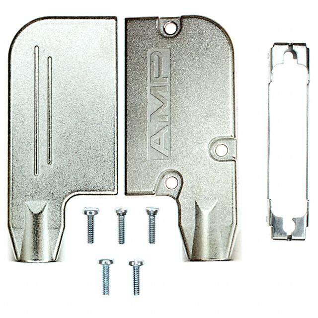
D sub:Layout 1 3/24/09 12:37 PM Page 20 D Cannon D-Subminiature Accessories Connector Saver High Reliability Connector Saver Engaging Face, Pin Side 21,95 ± 0,51 A (.864 ± .020) B C 5,97 ± 0,25 6,17 ± 0,25 (.235 ± .010) (.243 ± .010) CONTACT (SOCKET) 2X11˚ CONTACT 9˚ (PIN) SHELL SPACER SOCKET FRONT SHELL PIN FRONT NOTE: Hardware removed for clarity. Shell Part A B C Size Layout Number ± 0,40 (.015) ± 0,25 (.010) ± 0,25 (.010) DE 9 DEBMAM9PS 30,81 (1.213) 24,99 (.984) 16,92 (.666) DA 15 DABMAM15PS 39,14 (1.541) 33,32 (1.312) 25.25 (.994) DB 50 DBBMAM25PS 53,04 (2.088) 47,04 (1.852) 38,96 (1.534) DC 37 DCBMAM37PS 69,32 (2.729) 63,50 (2.500) 55,42 (2.182) DD 50 DDBMAM50PS 66,93 (2.635) 61,11 (2.406) 52,81 (2.079) Specifications Temperature: -55º C to 105º C Current Rating: 7 A Dielectric withstanding Voltage: 500 VAC at Sea Level Materials and Finishes Description Material Finish Shells Steel Yellow Chromate over Zinc Insulator White Thermoplastic, UL 94V-0 — Contacts Copper Alloy Gold Over Copper Locking Hardware Stainless Steel Passivated Dimensions shown in mm (inch) Specifications and dimensions subject to change www.ittcannon.com 20
D sub:Layout 1 3/24/09 12:37 PM Page 21 D Cannon D-Subminiature Accessories Miscellaneous Polarizing Plates Polarizing Scheme Material:Black plastic, 94-V-O rated Polarizing A B C D E F G H Keys Part Number A B Position 1 by Shell Size 2 DE 115398 1.208 (30.7) 0.629 (16) 3 DA 115398-1 1.535 (39,0) 0.629 (16) DB 115398-2 2.082 (52,9) 0.629 (16) 4 DC 115398-3 2.726 (69,2) 0.629 (16) 5 DD 115398-3 2.630 (66,8) 0.749 (19) 6 7 8 9 10 Cut Key on Cut Key on socket pin connector connector Right Angle Brackets (Used with 90º Printed Circuit Connector D*M, D*, D*C,/D*U) Material: Black Polyester, UL-94V-0 Rated D*/D*M Shell Part A B C D E F Size Number ± .015 ± .005 ± .010 ± .010 ± .010 ± .010 DE 015-0338-000 1.224 (31.1) .984 (24.0) .340 (8.63) .484 (12.3) 24.7 (6.27) .283 (7.2) DA 015-0339-000 1.552 (39.4) 1.312 (33.3) .340 (8.63) .484 (12.3) 24.7 (6.27) .283 (7.2) DB 015-0340-000 2.092 (53.1) 1.852 (47.0) .340 (8.63) .484 (12.3) 24.7 (6.27) .283 (7.2) DC 015-0341-000 2.740 (69.0) 2,500 (63.5) .340 (8.63) .484 (12.3) 24.7 (6.27) .283 (7.2) DD 015-0342-000 2.646 (67.2) 2.406 (61.1) .395 (10.0) .594 (15.1) .302 (7.67) .283 (7.2) D*C/D*U Shell Part A B C D E F Size Number ± .015 ± .005 ±.010 ± 010 ± .010 ± .010 DE 015-0348-000 1.224 (31.1) .984 (24.0) .340 (8.63) .484 (12.3) 24.7 (6.27) .283 (7.2) DA 015-0349-000 1.552 (39.4) 1.312 (33.3) .340 (8.63) .484 (12.3) 24.7 (6.27) .283 (7.2) DB 015-0350-000 2.092 (53.1) 1.852 (47.0) .340 (8.63) .484 (12.3) 24.7 (6.27) .283 (7.2) DC 015-0351-000 2.740 (69.0) 2,500 (63.5) .340 (8.63) .484 (12.3) 24.7 (6.27) .283 (7.2) DD 015-0352-000 2.646 (67.2) 2.406 (61.1) .395 (10.0) .594 (15.1) .302 (7.67) .283 (7.2) Wire Hole Fillers (D*MA Series Only) Material:Nylon Part Number Insert Type Pin DMA 51236-1 Socket DMA 51235-1 Pin Socket Insert this end first Dimensions shown in mm (inch) From Terminal end of Connector Specifications and dimensions subject to change www.ittcannon.com 21
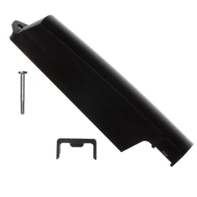
D sub:Layout 1 4/10/09 11:43 AM Page 22 D Cannon D-Subminiature Accessories Miscellaneous Dust Cap RAISEDGATEMARK R.TYP. 6,35 (.250) A B ITXTXC-XAXN-NXOXN 1,02 D .04WALL TYP. C B NOTE:Cdim.appliesatpointofmaximumIntegralinterfacelength. DrawingshownforBlackAnti-staticcaps. Dimensionsshownarereferenceonly. Dustcapsprovideprotectionfrommoisture anddustforunusedI/Oports. BlackAntistatic RedCaps (SurfaceResistivity (SurfaceResistivity ProductFeatures <1x10⁵ohm/sq) 105-1012ohm/sq) I.D. A B C D •DustCapsmeetthestaticdecaytest DE-59-20BA DE-59-20RC Socket 20,32(.800) 11,43(.450) 16,36(.644) 7,59(2.99) requirementsofMIL-B-81705C,TypeII. DA-59-20BA DA-59-20RC Socket 28,45(1.120) 11,68(.460) 24,59(.968) 7,62(.300) •DustCapshaveanintegralflangeforeasy DB-59-20BA DB-59-20RC Socket 42,42(1.670) 11,68(.460) 38,25(1.506) 7,49(.295) applicationandremoval DC-59-20BA DC-59-20RC Socket 58,93(2.320) 11,68(.460) 54,81(2.158) 7,37(.290) DD-59-20BA DD-59-20RC Socket 56,90(2.240) 14,48(.570) 53,11(2.091) 10,41(.410) DE-60-20BA DE-60-20RC Pin 21,84(.860) 12,95(5.10) 17,78(.700) 8,92(.351) DA-60-20BA DA-60-20RC Pin 30,48(1.200) 12,95(.510) 26,52(1.044) 9,02(.355) DB-60-20BA DB-60-20RC PIn 44,20(1.740) 13,46(.530) 39,60(1.559) 9,09(.358) MaterialsandFinishes DC-60-20BA DC-60-20RC Pin 60,71(2.390) 13,46(.530) 56,90(2.240) 9,37(.369) Material: Polyethylene DD-60-20BA DD-60-20RC Pin 58,17(2.290) 16.00(.630) 54,28(2.137) 12.04(.474) Interfacial Seal 10˚TYP. A 0,79+0,38-0.00 (.031+.015 - .000) B ø0,91+_0,18 (.036+_.007) Interfacialsealsprovidemoistureresistanceatthe DIA.TYP. matinginterface. ShellSize Layout PartNumber A B DE 9 DE53750 16,66(.656) 8,41(.331) ProductFeatures DA 15 DA53750-1 24,99(.984) 8,41(.331) •OtherInterfacialSealsintheComboD® DB 25 DB53750-2 38,881.531) 8,41(.331) layoutsareavailableuponrequest. DC 37 DC53750-3 55,14(2.171) 8,41(.331) DD 50 DD53750-4 52,78(2.078) 11,10(.437) DC 21WA4 075-0354-003 55,14(2.171) 8,41(.331) Material: SilasticSheet DE 15 273-0333-000 16,66(.656) 8,41(.331) DA 26 273-0334-000 24,99(.984) 8,41(.331) DB 44 273-0335-000 38,881.531) 8,41(.331) DC 62 273-0336-000 55,14(2.171) 8,41(.331) DD 78 273-0337-000 52,78(2.078) 11,10(.437) Potting Shell 15,20 (.600) + + 4,70(.185) 0,76 (.030) 3,25(.128) DIA. Pottingshellsaremoldedwithathinflange0,76 (.030)topermittheuseofDSubminiature ShellSize Layout PartNumber lockingdevices. DE 9 DE50904-1 DA 15 DA50905-1 MaterialsandFinishes DB 25 DB50906-1 Material: Nylon DC 37 DC50907-1 Color: Natural(white) DD 50 DD50908-1 Dimensionsshowninmm(inch) Specificationsanddimensionssubjecttochange www.ittcannon.com 22
D sub:Layout 1 3/24/09 12:37 PM Page 23 D Cannon D-Subminiature Accessories Index Standard RoHS Page StandardRoHS Page StandardRoHS Page Part # Part # # Part # Part # # Part # Part # # 075-0354-003 Same 22 DA22214 Same 18 DD121073-53 Same 4 250-8501-004 Same 5 DA24658 DA24658-28 9 DD19678-4 Same 10 250-8501-009 Same 5 DA50905-1 Same 22 DD19977-4 Same 10 250-8501-010 Same 5 DA51210 Same 12 DD20964 DD20964-32 9 250-8501-013 Same 5 DA51211 Same 12 DD21961 Same 18 273-0333-000 Same 22 DA51220-1 Same 15 DD21962 Same 19 273-0334-000 Same 22 DA53750-1 Same 22 DD24661 Same 9 273-0335-000 Same 22 DA-59-20 Same 22 DD50908-1 Same 22 273-0336-000 Same 22 DA-60-20 Same 22 DD51216 Same 12 273-0337-000 Same 22 DABMA15PS Same 20 DD51217 Same 12 980-2000-345 Same 6 DABS-15 Same 11 DD51223-1 Same 15 980-2000-346 Same 6 DB115339-22 Same 9 DD53750-4 Same 22 980-2000-347 Same 6 DB121073-151 Same 4 DD-59-20 Same 22 980-2000-348 Same 6 DB121073-51 Same 4 DD-60-20 Same 22 980-2000-350 Same 12 DB19678-2 DB19678-213 10 DDBMA50PS Same 20 980-2000-351 Same 12 DB19977-2 DB19977-69 9 DE111919 Same 19 980-2000-352 Same 12 DB20962 DB20962-30 10 DE111920 Same 18 980-2000-353 Same 12 DB22254 Same 18 DE115339-20 Same 11 980-2000-354 Same 12 DB22255 Same 19 DE121073-154 Same 4 D110277 Same 16 DB24659 DB24659-27 9 DE121073-54 Same 4 D110278 Same 16 DB50906-1 Same 22 DE19977-5 DE19977-72 10 D110279 Same 16 DB51212 Same 12 DE24657 DE24657-29 9 D110280 Same 16 DB51213 Same 12 DE44994 DE44994-14 9 D110550 Same 17 DB51221-1 Same 15 DE50904-1 Same 22 D110551 Same 17 DB53750-2 Same 22 DE51218 Same 12 D121073-19 Same 5 DB-59-20 Same 22 DE51219 Same 12 D121073-39 Same 14 DB-60-20 Same 22 DE51224-1 Same 15 D121073-42 Same 14 DBBMA25PS Same 20 DE53750 Same 22 D20418-2 D20418-134 14 DBBS-25 Same 11 DE-59-20 Same 22 D20418-39 D20418-136 14 DC115339-23 Same 11 DE-60-20 Same 22 D20418-50 D20418-135 14 DC121073-152 Same 4 DEBMA9PS Same 20 D20418-74 D20418-137 14 DC121073-52 Same 4 DEBS-9 Same 11 D20419 D20419-211 13 DC19678-3 DC19678-214 9 D20419-104 D20419-214 13 DC19977-3 DC19977-70 9 D20419-18 D20419-212 13 DC20963 DC20963-27 9 D20419-21 D20419-213 13 DC22070 Same 19 D20420 D20420-157 13 DC22071 Same 18 D20420-13 D20420-158 13 DC24660 Same 7 D20420-15 D20420-159 13 DC50907-1 Same 22 D20420-86 D20420-160 13 DC51214 Same 12 D53018 Same 15 DC51215 Same 12 DA115339-21 Same 11 DC51222-1 Same 15 DA121073-150 Same 4 DC53750-3 Same 22 DA121073-50 Same 4 DC-59-20 Same 22 DA19678-1 DA19678-212 10 DC-60-20 Same 22 DA19977-1 DA19977-68 10 DCBMA37PS Same 20 DA20961 DA20961-26 9 DD115339-24 Same 11 DA22213 Same 19 DD121073-153 Same 4 Dimensions shown in mm (inch) Specifications and dimensions subject to change www.ittcannon.com 23
D sub:Layout 1 3/24/09 12:37 PM Page 24 Product Safety and Warranty 11.. MMAATTEERRIIAALL CCOONNTTEENNTT AANNDD PPHHYYSSIICCAALL 44..DDIISSPPOOSSAALL FFOORRMM Incineration of certain materials may release This publication is not to be construed as an Electrical connectors do not usually contain noxious or even toxic fumes. offer. It is intended merely as an invitation to hazardous materials. They contain conduct- make an offer. By this publication, Cannon ing and non-conducting materials and can 55..AAPPPPLLIICCAATTIIOONN does not assume responsibility or any liabili- be divided into two groups. Connectors with exposed contacts should ty for any patent infringements or other a) Printed circuit types and low cost audio not be selected for use on the current supply rights of third parties which may result from types which employ all plastic insulators and side of an electrical circuit, because an elec- its use. casings. tric shock could result from touching b) Rugged, Fire Barrier and High Reliability exposed contacts on an unmated connector. Reprinting this publication is generally per- types with metal casings and either natural Voltages in excess of 30 V ac or 42.5 V dc are mitted, indicating the source. However, rubber, synthetic rubber, plastic or glass potentially hazardous and care should be Cannon's prior consent must be obtained in insulating materials. Contact materials vary taken to ensure that such voltages cannot be all cases. “Engineered for life” is a registered with type of connector and also application transmitted in any way to exposed metal trademark of ITT Corporation ©2006. All and are usually manufactured from either: parts of the connector body. The connector other trademarks or registered trademarks Copper, copper alloys, nickel, alumel, and wiring should be checked, before mak- are property of their respective owners. All chromel or steel. In special applications, ing live, to have no damage to metal parts or dates subject to change without notice. other alloys may be specified. insulators, no solder blobs, loose strands, conducting lubricants, swarf, or any other Commodities in this catalog may be 22.. FFIIRREE CCHHAARRAACCTTEERRIISSTTIICCSS AANNDD EELLEECCTTRRIICC undesired conducting particles. Circuit controlled for export by the International SSHHOOCCKK HHAAZZAARRDD resistance and continuity check should be Traffic in Arms Regulations (ITAR) and Export TThheerree iiss nnoo ffiirree hhaazzaarrdd wwhheenn tthhee ccoonnnneecc-- made to make certain that there are no high Administration Regulations (EAR) when ttoorr iiss ccoorrrreeccttllyy wwiirreedd aanndd uusseedd wwiitthhiinn tthhee resistance joints or spurious conducting specifically designed modified, or configured ssppeecciiffiieedd ppaarraammeetteerrss.. IInnccoorrrreecctt wwiirriinngg oorr paths. Always use the correct application for articles controlled by the United States aasssseemmbbllyy ooff tthhee ccoonnnneeccttoorr oorr ccaarreelleessss uussee tools as specified in the Data Sheet/Catalog. Government. ooff mmeettaall ttoooollss oorr ccoonndduuccttiivvee fflluuiiddss,, oorr Do not permit untrained personnel to wire, ttrraannssiitt ddaammaaggee ttoo aannyy ooff tthhee ccoommppoonneenntt assemble or tamper with connectors. For ppaarrttss mmaayy ccaauussee eelleeccttrriicc sshhoocckk oorr bbuurrnnss.. operation voltage please see appropriate LLiivvee cciirrccuuiittss mmuusstt nnoott bbee bbrrookkeenn bbyy sseeppaa-- national regulations. rraattiinngg mmaatteedd ccoonnnneeccttoorrss aass tthhiiss mmaayy ccaauussee aarrcciinngg,, iioonniizzaattiioonn aanndd bbuurrnniinngg..Heat IIMMPPOORRTTAANNTT GGEENNEERRAALL IINNFFOORRMMAATTIIOONN dissipation is greater at maximum resistance ((ii)) AAiirr aanndd ccrreeeeppaaggee ppaatthhss//OOppeerraattiinngg vvoolltt-- in a circuit. Hot spots may occur when resist- aaggee.. The admissible operating voltages ance is raised locally by damage, e.g. cracked depend on the individual applications and or deformed contacts, broken strands of the valid national and other applicable safe- wire. Local overheating may also result from ty regulations. the use of the incorrect application tools or For this reason the air and creepage path from poor quality soldering or slack screw data are only reference values. Observe terminals. Overheating may occur if the rat- reduction of air and creepage paths due to ings in the product Data Sheet/Catalog are PC board and/or harnessing. exceeded and can cause breakdown of insu- lation and hence electric shock. If heating is ((iiii)) TTeemmppeerraattuurree allowed to continue it intensifies by further All information given are temperature limits. increasing the local resistance through loss The operation temperature depends on the of temper of spring contacts, formation of individual application. oxide film on contacts and wires and leakage currents through carbonization of insulation ((iiiiii)) OOtthheerr iimmppoorrttaanntt iinnffoorrmmaattiioonn and tracking paths. Fire can then result in Cannon continuously endeavors to improve the presence of combustible materials and their products. Therefore, Cannon products this may release noxious fumes. Overheating may deviate from the description, technical may not be visually apparent. Burns may data and shape as shown in this catalog and result from touching overheated compo- data sheets. nents. 33..HHAANNDDLLIINNGG ITT Cannon, a Division of ITT Inc., Care must be taken to avoid damage manufactures the highest quality products to any component parts of electrical connec- available in the marketplace; however these tors during installation and use. Although products are intended to be used in there are normally no sharp edges, care accordance with the specifications in this must be taken when handling certain com- publication. Any use or application that ponents to avoid injury to fingers. Electrical deviates from the stated operating connectors may be damaged in transit to the specifications is not recommended and may customers, and damage may result in cre- be unsafe. No information and data ation of hazards. Products should therefore contained in this publication shall be be examined prior to installation/use and construed to create any liability on the part rejected if found to be damaged. of Cannon. Any new issue of this publication shall automati-cally invalidate and supersede any and all previous issues. www.ittcannon.com 24
Circular/Filter/Hermetic Connectors As a world leader in circular, filter, and hermetic connectors, ITT can leverage its design and manufacturing expertise to fit virtually any application. Our expertise includes fast positive mating for a wide range of military applications, as well as numerous sizes and contact configurations for various harsh environments. D-Subminiature Connectors Cannon invented D-sub connectors in 1952. Our family of D-Subs now includes combinations of signal, power and RF, as well as severe service sealed connectors. Cannon D-Subs are available with an extensive line of backshells and accessories and are one of the most economical shielded connector solutions available. Fiber Optic Connectors and Cable Assemblies Cannon fiber optic solutions provide an excellent performance/ cost value. Performance may be tailored to the end system, with our use of superior materials and bonding agents providing highly effective solutions. Our wide variety of products include fiber optic hybrid contacts, multi-channel, rack and panel and hi- rel assemblies. Microminiature Connectors Developed first by Cannon in the 1960s, Microminiature Connectors offer high performance and reliability with exceptional versatility. Available in rectangular, circular and strip-style configurations for countless applications, many of our highly engineered Microminiature connector products meet critical customer demands in multiple applications across the Aerospace & Defense industry. Rack and Panel Connectors Pioneered by Cannon during the 1930s, our Rack & Panel Connectors offer an unmatched variety of shell configurations and insert arrangements, as well as materials, plating and contact options. Today, we are recognized as an industry leader, offering an unparalleled range of off-the-shelf and custom Rack & Panel products to align with customer needs. RF Connectors ITT Cannon has been providing interconnect products to the Microwave and RF industry since 1963 (formerly The Sealectro Corporation). The RF 50 & 75 Ohm product lines cover UHF band through Ku band requirements. These connectors and cable assemblies are available with a thread type, snap type, bayonet type or slide on coupling method. The frequencies range from DC to 18+ GHz. ITT Cannon is a leading global manufacturer of connector products serving international customers in the aerospace and defense, medical, energy, transportation and industrial end markets. Whether delivering critical specs to aircraft pilots, streaming data through communications satellites or enabling ultrasound technology that gives an expectant mother the first glimpse of her unborn child, Cannon connects the world’s most important information with the people who need it. To learn more, visit www.ittcannon.com
D sub:Layout 1 3/24/09 12:37 PM Page 26 Customer Support Locations CHINA Tuopandun Industrial Area, Jinda Cheng, Xiner Village, Shajing Town, Baoan District, Shenzhen City, Guangdong, China 518125 phone: +86.755.2726.7888 fax: +86.755.2726.7515 GERMANY Cannonstrasse 1 Weinstadt, 71384 phone: +49.7151.699.0 fax: +49.7151.699.217 FRANCE 15, Boulevard Robert Thiboust Serris, France 77700 phone: +33.1.60.04.93.93 fax: +33.1.60.04.93.90 HONG KONG Units 2405-6, 24/F, ING Tower 308 Des Voeux Road Central Hong Kong phone: +852.2732.2720 fax: +852.2732.2919 ITALY Corso Europa 41/43 Lainate (MI), Italy 20020 phone: +39.02938721 fax: +39.0293872300 JAPAN 11-3, 5 Chome,Hibarigaoka, Zama-shi Kanagawa, Japan 228-0003 phone: +81.462.57.2010 fax: +81.462.57.1680 UK Jays Close, Viables Estate Basingstoke, RG22 4BA phone: +44.1256.311200 fax: +44.1256.323356 USA 56 Technology Drive Irvine, CA 92618 phone: 1.800.854.3028 fax: 1.714.628.2142 ©2017 ITT Inc. | ITT Cannon D-Subminiature Accessories Catalog | 20170724 The “ITT Engineered Blocks“ symbol, “Engineered for life," “ITT” and “Cannon“ are registered trademarks of ITT Inc. Specification and other data are based on information available at the time of printing, and are subject to change without notice. www.ittcannon.com Our facility is not currently certified by the DLA and this product is not covered by the QPL/ QML.