 Datasheet下载
- 型号: 880
- 制造商: Keystone Electronics
- 库位|库存: xxxx|xxxx
- 要求:
| 数量阶梯 | 香港交货 | 国内含税 |
| +xxxx | $xxxx | ¥xxxx |
查看当月历史价格
查看今年历史价格
880产品简介:
ICGOO电子元器件商城为您提供880由Keystone Electronics设计生产,在icgoo商城现货销售,并且可以通过原厂、代理商等渠道进行代购。 880价格参考。Keystone Electronics880封装/规格:万用表 - 专用, Testing Components LCR Meter。您可以下载880参考资料、Datasheet数据手册功能说明书,资料中有880 详细功能的应用电路图电压和使用方法及教程。
B&K Precision 880是一款专用于电子测量的数字万用表,适用于多种场景,包括但不限于以下方面:

1. 电路调试与维修:该型号适用于电子工程师和技术人员在调试和维修电路时使用。可以精确测量电压、电流、电阻等参数,帮助定位故障点。

2. 教育与培训:在学校或培训机构中,B&K Precision 880是理想的教学工具,学生可以通过实际操作学习基础电学知识和测量技能。

3. 实验室测试:在科研或开发实验室中,这款万用表可用于验证电路设计、评估元件性能以及进行数据记录。

4. 生产线质量控制:在制造业中,880型万用表可用于产品质量检测,确保产品符合电气规格要求。

5. 现场服务与维护:由于其便携性和可靠性,这款万用表适合技术人员在现场对各种设备进行快速检查和故障诊断。

6. DIY项目与爱好者使用:对于业余电子爱好者,它可以用来完成个人项目中的测量任务,如制作小型电子产品或改装现有设备。

总之,B&K Precision 880以其高精度、多功能性和耐用性,成为各类电子测量应用的理想选择。
| 参数 | 数值 |
| 产品目录 | |
| 描述 | ROUND SPACER #4 NYLON 3/4"支架与垫片 .750 Rd Clr Hle spcr .250 OD #4 Nylon |
| 产品分类 | |
| 品牌 | Keystone Electronics |
| 产品手册 | |
| 产品图片 |
|
| rohs | 符合RoHS无铅 / 符合限制有害物质指令(RoHS)规范要求 |
| 产品系列 | 支架与垫片,Keystone Electronics 880- |
| 数据手册 | 点击此处下载产品Datasheethttp://www.keyelco.com/product-pdf.cfm?p=4784 |
| 产品型号 | 880 |
| RoHS指令信息 | |
| 产品目录绘图 |
|
| 产品种类 | 支架与垫片 |
| 公母 | 母头, 母头 |
| 其它名称 | 880K |
| 内径 | 6.4 mm |
| 商标 | Keystone Electronics |
| 外径 | 6.4 mm |
| 工厂包装数量 | 100 |
| 有丝/无丝 | 无螺纹 |
| 材料 | 尼龙 |
| 板间高度 | 0.750"(19.05mm)3/4" |
| 标准包装 | 10 |
| 特性 | - |
| 直径-外部 | 0.250"(6.35mm)1/4" |
| 类型 | 圆形垫片 |
| 螺纹/螺丝/孔尺寸 | #4,0.120"(3.05mm)内径 |
| 重量 | - |
| 镀层 | - |
| 长度 | 19.1 mm |
| 长度-总 | 0.750"(19.05mm)3/4" |
| 颜色 | 自然色 |


- 商务部:美国ITC正式对集成电路等产品启动337调查
- 曝三星4nm工艺存在良率问题 高通将骁龙8 Gen1或转产台积电
- 太阳诱电将投资9.5亿元在常州建新厂生产MLCC 预计2023年完工
- 英特尔发布欧洲新工厂建设计划 深化IDM 2.0 战略
- 台积电先进制程称霸业界 有大客户加持明年业绩稳了
- 达到5530亿美元!SIA预计今年全球半导体销售额将创下新高
- 英特尔拟将自动驾驶子公司Mobileye上市 估值或超500亿美元
- 三星加码芯片和SET,合并消费电子和移动部门,撤换高东真等 CEO
- 三星电子宣布重大人事变动 还合并消费电子和移动部门
- 海关总署:前11个月进口集成电路产品价值2.52万亿元 增长14.8%
PDF Datasheet 数据手册内容提取
Adafruit LED Backpacks Created by lady ada Last updated on 2018-08-22 03:30:15 PM UTC
Guide Contents Guide Contents 2 Overview 4 1.2" 8x8 Matrix 7 (https://adafru.it/aPT)Mini 8x8 Matrix Software 10 0.8" 8x8 Matrix 13 Mini 8x8 Matrix Software 16 0.54" Alphanumeric 19 Attaching the Backpack 19 Attaching Header 23 Prepare the header strip: 23 Add the Backpack: 24 Downloading the Arduino Library 24 Wiring! 25 Load Demo 26 Library Reference 27 ASCII data 28 Writing Data 28 0.56" 7-Segment Backpack 30 Seven-Segment Backpack Firmware 33 1.2" 7-segment Backpack 35 Arduino Wiring - R3 and later 40 Arduino Due and Other 3.3v Processors 40 Arduino "Classic" Wiring 40 Seven-Segment Backpack Firmware 41 Bi-Color 8x8 Matrix 43 Bi-Color 8x8 LED Backpack Firmware 48 Schematic 50 Bi-Color 24 Bargraph 51 Attaching the bar-graph modules 51 Soldering on breadboard pins 55 Bi-Color Bargraph LED Backpack Wiring & Firmware 57 Connecting Multiple Backpacks 60 Wire it Up 60 Configure the Address 61 Changing I2C Address 62 Changing Addresses 62 Changing the address in your code 63 F.A.Q. 65 I want to use these modules with other non-Arduino, how can I port the code? 65 I'd like to use these backpacks with Python / Linux (e.g. a Raspberry Pi) 65 I am having strange problems when combining Adafruit Motor Shield/Servo Shield (PCA9685 based) with the Adafruit LED Matrix/7Seg Backpacks 65 What is the current draw of the backpacks? 65 © Adafruit Industries https://learn.adafruit.com/adafruit-led-backpack Page 2 of 74
Downloads 66 Software 66 Files 66 HT16K33 8x16 LED Backpack Breakout 66 8x8 0.8" LED Backpack 67 8x8 1.2" LED Backpack 68 8x8 1.2" Bi-Color LED Backpack 69 16x8 1.2" LED Backpacks 70 Quad 0.56" 7-Segment 71 Quad 0.54" 14-segment Alphanumeric 72 Quad 1.2" 7-Segment 72 Bicolor 24-Bargraph 73 © Adafruit Industries https://learn.adafruit.com/adafruit-led-backpack Page 3 of 74
Overview What's better than a single LED? Lots of LEDs! A fun way to make a small display is to use an 8x8 matrix (https://adafru.it/aLG) or a 4-digit 7-segment display (https://adafru.it/aLH). Matrices like these are 'multiplexed' - so to control 64 LEDs you need 16 pins. That's a lot of pins, and there are driver chips like the MAX7219 (http://adafru.it/453) that can control a matrix for you but there's a lot of wiring to set up and they take up a ton of space. Here at Adafruit we feel your pain! After all, wouldn't it be awesome if you could control a matrix without tons of wiring? That's where these adorable LED matrix backpacks come in. We have them in quite a few flavors! Adorable Mini 8x8 (https://adafru.it/ttf) Classic 1.2" 8x8 (round and square dots) (https://adafru.it/ttA) 4-digit 0.56" 7-segment (https://adafru.it/ttB) 4-digit 1.2" 7-segment (https://adafru.it/ttC) 4-digit 0.54" 14-segment Alphanumeric (https://adafru.it/ttD) Bi-color 8x8 (http://adafru.it/902) Bi-color Bargraph (http://adafru.it/1721) © Adafruit Industries https://learn.adafruit.com/adafruit-led-backpack Page 4 of 74
The matrices use a driver chip that does all the heavy lifting for you: They have a built in clock so they multiplex the display. They use constant-current drivers for ultra-bright, consistant color (the images above are photographed at the dimmest setting to avoid overloading our camera!), 1/16 step display dimming, all via a simple I2C interface. The backpacks come with address-selection jumpers so you can connect up to four mini 8x8's or eight 7-segments (or a combination, such as four mini 8x8's and four 7-segments, etc) on a single I2C bus. © Adafruit Industries https://learn.adafruit.com/adafruit-led-backpack Page 5 of 74
The product kit comes with a fully tested and assembled LED backpack, a 4-pin header and the matrix of your choice. A bit of soldering is required to attach the matrix onto the backpack but its very easy to do and only takes about 5 minutes. Of course, in classic Adafruit fashion, we also have a detailed tutorial showing you how to solder, wire and control the display. We even wrote a very nice library for the backpacks so you can get running in under half an hour, displaying images on the matrix or numbers on the 7-segment. If you've been eyeing matrix displays but hesitated because of the complexity, his is the solution you've been looking for! © Adafruit Industries https://learn.adafruit.com/adafruit-led-backpack Page 6 of 74
1.2" 8x8 Matrix This version of the LED backpack is designed for the 1.2" 8x8 matrices. They measure only 1.2"x1.2" so its a shame to use a massive array of chips to control it. This backpack solves the annoyance of using 16 pins or a bunch of chips by having an I2C constant-current matrix controller sit neatly on the back of the PCB. The controller chip takes care of everything, drawing all 64 LEDs in the background. All you have to do is write data to it using the 2-pin I2C interface. There are two address select pins so you can select one of 8 addresses to control up to 8 of these on a single 2-pin I2C bus (as well as whatever other I2C chips or sensors you like). The driver chip can 'dim' the entire display from 1/16 brightness up to full brightness in 1/16th steps. It cannot dim individual LEDs, only the entire display at once. These instruction apply to the 1.2" Matrix only! If you have a Bi-Color or 0.8" square matrix, follow the links on the left side of the page. When you buy a pack from Adafruit, it comes with the fully tested and assembled backpack as well as a 8x8 matrix in one of the colors we provide (say, red, yellow or green). You'll need to solder the matrix onto the backpack but its an easy task. WATCH OUT! THE MATRIX MUST BE INSTALLED THE RIGHT WAY! First look for the line of text on the side of the LED matrix © Adafruit Industries https://learn.adafruit.com/adafruit-led-backpack Page 7 of 74
WATCH OUT! THE MATRIX MUST BE INSTALLED THE RIGHT WAY! Find the corner of the backpack with a filled in dot. Make sure that the text on the side of the matrix is on the same side as the filled dot WATCH OUT! THE MATRIX MUST BE INSTALLED THE RIGHT WAY! Slide the matrix into the backpack and flip it over. Triple check that the text is on the same side as the From Adafruit text © Adafruit Industries https://learn.adafruit.com/adafruit-led-backpack Page 8 of 74
Solder in all 16 pins Then clip the matrix leads short © Adafruit Industries https://learn.adafruit.com/adafruit-led-backpack Page 9 of 74
Now you're ready to wire it up to a microcontroller. We'll assume you want to use a 4pin header. You can also of course solder wires directly. Place a 4-pin piece of header with the LONG pins down into the breadboard. Place the soldered backpack on top of the header. Solder the four pins That's it! now you're ready to run the firmware! (https://adafru.it/aPT)Mini 8x8 Matrix Software We wrote a basic library to help you work with the mini 8x8 matrix backpack. The library is written for the Arduino and will work with any Arduino as it just uses the I2C pins. The code is very portable and can be easily adapted to any I2C- © Adafruit Industries https://learn.adafruit.com/adafruit-led-backpack Page 10 of 74
capable micro. Wiring to the matrix is really easy Connect CLK to the I2C clock - on Arduino UNO thats Analog #5, on the Leonardo its Digital #3, on the Mega its digital #21 Connect DAT to the I2C data - on Arduino UNO thats Analog #4, on the Leonardo its Digital #2, on the Mega its digital #20 Connect GND to common ground Connect VCC+ to power - 5V is best but 3V also seems to work for 3V microcontrollers. Next, download the Adafruit LED Backpack library from github (https://adafru.it/aLI) . To download click the DOWNLOADS button in the top right corner, rename the uncompressed folder Adafruit_LEDBackpack. Check that the Adafruit_LEDBackpack folder contains Adafruit_LEDBackpack.cpp and Adafruit_LEDBackpack.h Place the Adafruit_LEDBackpack library folder your arduinosketchfolder/libraries/ folder. You may need to create the libraries subfolder if its your first library. You'll also need to download the Adafruit GFX library (https://adafru.it/aJa) that provides the graphics drawing routines. Restart the IDE. Once you've restarted you should be able to select the File->Examples->Adafruit_LEDBackpack->matrix88 example sketch. Upload it to your Arduino as usual. You should see a basic test program that goes through a bunch of different drawing routine Once you're happy that the matrix works, you can write your own sketches. The 8x8 matrix supports everything the Adafruit GFX library - drawing pixels, lines, rectancles, circles, triangles, roundrects, and small bitmaps. For more details check out the GFX page which will detail all of the GFX routines (https://adafru.it/aPx). All the drawing routines only change the display memory kept by the Arduino. Don't forget to call writeDisplay() after drawing to 'save' the memory out to the matrix via I2C. © Adafruit Industries https://learn.adafruit.com/adafruit-led-backpack Page 11 of 74
There are also a few small routines that are special to the matrix: setBrightness(brighness)- will let you change the overall brightness of the entire display. 0 is least bright, 15 is brightest and is what is initialized by the display when you start. You can call this function at any time to change the brightness of the -entire- display blinkRate(rate) - You can blink the entire display. 0 is no blinking. 1, 2 or 3 is for display blinking.You can call this function at any time to change the blink rate of the -entire- display The default orientation for graphics commands on this display places pixel (0,0) at the top-left when the header is at the left and Adafruit logo at the right. To use the matrix as shown above (header at top, logo at bottom), call matrix.setRotation(3) before issuing graphics commands. © Adafruit Industries https://learn.adafruit.com/adafruit-led-backpack Page 12 of 74
0.8" 8x8 Matrix This version of the LED backpack is designed for these very cute miniature 8x8 matrices. They measure only 0.8"x0.8" so its a shame to use a massive array of chips to control it. This backpack solves the annoyance of using 16 pins or a bunch of chips by having an I2C constant-current matrix controller sit neatly on the back of the PCB. The controller chip takes care of everything, drawing all 64 LEDs in the background. All you have to do is write data to it using the 2- pin I2C interface. There are two address select pins so you can select one of 4 addresses to control up to 4 of these on a single 2-pin I2C bus (as well as whatever other I2C chips or sensors you like). The driver chip can 'dim' the entire display from 1/16 brightness up to full brightness in 1/16th steps. It cannot dim individual LEDs, only the entire display at once. These instruction apply to the 0.8" Matrix only! If you have a Bi-Color or 1.2" square matrix, follow the links on the left side of the page. When you buy a pack from Adafruit, it comes with the fully tested and assembled backpack as well as a 8x8 matrix in one of the colors we provide (say, red, yellow or green). You'll need to solder the matrix onto the backpack but its an easy task. Remove the parts from packaging and place the LED matrix OVER the silkscreen side. It can go 'either way' - the matrix is symmetric so as long as it goes onto the front it will work in any orientation. Do not solder the matrix over the chip on the back of the backpack - it will not work then! © Adafruit Industries https://learn.adafruit.com/adafruit-led-backpack Page 13 of 74
Turn the backpack over so its sitting flat on the matrix. Solder all 16 pins. © Adafruit Industries https://learn.adafruit.com/adafruit-led-backpack Page 14 of 74
Clip the long pins. Now you're ready to wire it up to a microcontroller. We'll assume you want to use a 4pin header. You can also of course solder wires directly. Place a 4-pin piece of header with the LONG pins down into the breadboard. © Adafruit Industries https://learn.adafruit.com/adafruit-led-backpack Page 15 of 74
Place the soldered backpack on top of the header. Solder 'em! That's it! now you're ready to run the firmware! Mini 8x8 Matrix Software We wrote a basic library to help you work with the mini 8x8 matrix backpack. The library is written for the Arduino and will work with any Arduino as it just uses the I2C pins. The code is very portable and can be easily adapted to any I2C- capable micro. Wiring to the matrix is really easy Connect CLK to the I2C clock - on Arduino UNO thats Analog #5, on the Leonardo its Digital #3, on the Mega its digital #21 Connect DAT to the I2C data - on Arduino UNO thats Analog #4, on the Leonardo its Digital #2, on the Mega its digital #20 Connect GND to common ground Connect VCC+ to power - 5V is best but 3V also seems to work for 3V microcontrollers. Next, download the Adafruit LED Backpack library from github (https://adafru.it/aLI) . To download click the DOWNLOADS button in the top right corner, rename the uncompressed folder Adafruit_LEDBackpack. Check that the Adafruit_LEDBackpack folder contains Adafruit_LEDBackpack.cpp and Adafruit_LEDBackpack.h Place © Adafruit Industries https://learn.adafruit.com/adafruit-led-backpack Page 16 of 74
the Adafruit_LEDBackpack library folder your arduinosketchfolder/libraries/ folder. You may need to create the libraries subfolder if its your first library. You'll also need to download the Adafruit GFX library (https://adafru.it/aJa) that provides the graphics drawing routines. Follow the same instructions as above, but with Adafruit_GFX instead of Adafruit_LEDBackpack. Restart the IDE. Once you've restarted you should be able to select the File->Examples->Adafruit_LEDBackpack->matrix88 example sketch. Upload it to your Arduino as usual. You should see a basic test program that goes through a bunch of different drawing routines Once you're happy that the matrix works, you can write your own sketches. The 8x8 matrix supports everything the Adafruit GFX library - drawing pixels, lines, rectancles, circles, triangles, roundrects, and small bitmaps. For more details check out the GFX page which will detail all of the GFX routines (https://adafru.it/aPx). All the drawing routines only change the display memory kept by the Arduino. Don't forget to call writeDisplay() after drawing to 'save' the memory out to the matrix via I2C. There are also a few small routines that are special to the matrix: setBrightness(brighness)- will let you change the overall brightness of the entire display. 0 is least bright, 15 is brightest and is what is initialized by the display when you start blinkRate(rate) - You can blink the entire display. 0 is no blinking. 1, 2 or 3 is for display blinking. © Adafruit Industries https://learn.adafruit.com/adafruit-led-backpack Page 17 of 74
The default orientation for graphics commands on this display places pixel (0,0) at the top-left when the header is at the top and Adafruit logo at the bottom. matrix.setRotation() can be used to use the display in other orientations. © Adafruit Industries https://learn.adafruit.com/adafruit-led-backpack Page 18 of 74
0.54" Alphanumeric (https://adafru.it/l3c) This version of the LED backpack is designed for two dual 14-segment "Alphanumeric" displays. These 14-segment displays normally require 18 pins (4 'characters' and 14 total segments each) This backpack solves the annoyance of using 18 pins or a bunch of chips by having an I2C constant-current matrix controller sit neatly on the back of the PCB. The controller chip takes care of everything, drawing all the LEDs in the background. All you have to do is write data to it using the 2-pin I2C interface. There are three address select pins so you can select one of 8 addresses to control up to 8 of these on a single 2-pin I2C bus (as well as whatever other I2C chips or sensors you like). The driver chip can 'dim' the entire display from 1/16 brightness up to full brightness in 1/16th steps. It cannot dim individual LEDs, only the entire display at once. Attaching the Backpack When you buy a pack from Adafruit, it comes with the fully tested and assembled backpack as well as two dual 14-segment display in one of the colors we provide (say, red, yellow, blue or green). You'll need to solder the matrix onto the backpack but it's an easy task. Remove the parts from packaging and place the LED matrices OVER the silkscreen side. DO NOT PUT THE DISPLAY ON UPSIDE DOWN OR IT WONT WORK!! Check the image below to make sure the 'decimal point' dots are on the bottom, matching the silkscreen. © Adafruit Industries https://learn.adafruit.com/adafruit-led-backpack Page 19 of 74
Turn the backpack over so it is sitting flat on the matrix. Solder all of the pins! © Adafruit Industries https://learn.adafruit.com/adafruit-led-backpack Page 20 of 74
© Adafruit Industries https://learn.adafruit.com/adafruit-led-backpack Page 21 of 74
Clip the long pins. © Adafruit Industries https://learn.adafruit.com/adafruit-led-backpack Page 22 of 74
Check your work, making sure each pin is nicely soldered, and there's no cold solder joints or shorted pins Attaching Header Prepare the header strip: Cut the strip to length if necessary. It will be easier to solder if you insert it into a breadboard - long pins down Add the Backpack: Place the backpack board over the pins so that the short pins poke through the breakout pads © Adafruit Industries https://learn.adafruit.com/adafruit-led-backpack Page 23 of 74
Solder all 5 pins! That's it! now you're ready to run the firmware on your Arduino! Downloading the Arduino Library We wrote a basic library to help you work with the alphanumeric backpack. The library is written for the Arduino and will work with any Arduino as it just uses the I2C pins. The code is very portable and can be easily adapted to any I2C- capable micro. Begin by downloading our Adafruit LED Backpack library from github (https://adafru.it/aLI). You can do that by visiting the github repo and manually downloading or, easier, just click this button to download the zip https://adafru.it/dxh https://adafru.it/dxh Rename the uncompressed folder Adafruit_LEDBackpack and check that the Adafruit_LEDBackpack folder contains Adafruit_LEDBackpack.cpp and Adafruit_LEDBackpack.h Place the Adafruit_LEDBackpack library folder your arduinosketchfolder/libraries/ folder. You may need to create the libraries subfolder if its your first library. Restart the IDE. We also have a great tutorial on Arduino library installation at: http://learn.adafruit.com/adafruit-all-about-arduino-libraries-install-use (https://adafru.it/aYM) You'll also need to download the Adafruit GFX library - even though this particular backpack doesn't use it! Its just one of those Arduino dependencies! You can grab the Adafruit GFX library from github (https://adafru.it/aJa) or download by clicking below. https://adafru.it/cBB https://adafru.it/cBB Rename the uncompressed folder Adafruit_GFX and check that the Adafruit_GFX folder contains Adafruit_GFX.cpp and Adafruit_GFX.h Place the Adafruit_GFX library folder your arduinosketchfolder/libraries/ folder like you did with the LED backpacks © Adafruit Industries https://learn.adafruit.com/adafruit-led-backpack Page 24 of 74
Wiring! Nex up, let's wire it up to an Arduino. We'll be using an Arduino. Connect CLK to the I2C clock - on Arduino UNO thats Analog #5, on the Leonardo it's Digital #3, on the Mega it's digital #21 Connect DAT to the I2C data - on Arduino UNO thats Analog #4, on the Leonardo it's Digital #2, on the Mega it's digital #20 Connect GND to common ground Connect VCC+ to power - 5V is best but 3V will work if that's all you've got (it will be dimmer) Connect Vi2c to your microcontroller's logic level (3-5V) - If you're using an Arduino, this is almost certainly 5V. If its a 3V Arduino such as a Due, connect it to 3V Both Vi2c and Vcc MUST be connected to 3 to 5VDC! Vcc is for the LED driver power, Vi2c is what sets the logic level for communication to the chip. Load Demo Restart the Arduino IDE and load up the File->Adafruit_LEDBackpack->quadalphanum demo © Adafruit Industries https://learn.adafruit.com/adafruit-led-backpack Page 25 of 74
Upload to your Arduino, and open up the Serial console at 9600 baud speed. You'll see each digit light up all the segments, then the display will scroll through the 'font table' showing every character that it knows how to display. Finally, you'll get a notice to start typing into the serial console. Type a message and hit return, you'll see it scroll onto the display! © Adafruit Industries https://learn.adafruit.com/adafruit-led-backpack Page 26 of 74
Library Reference For the quad displays, we have a special object that can handle ascii data for easy printing. You can create the object with Adafruit_AlphaNum4 alpha4 = Adafruit_AlphaNum4(); There's no arguments or pins because the backpacks use the fixed I2C pins. By default, the address is 0x70, but you can pass in the I2C address used when you initialize the display with begin alpha4.begin(0x70); // pass in the address Next up, the segments can be turned on/off for each digit by writing the 'raw' bitmap you want, for example, all the LEDs off on digit #3 is alpha4.writeDigitRaw(3, 0x0); All the segments on for digit #0 is alpha4.writeDigitRaw(0, 0x3FFF); This is the segment map: © Adafruit Industries https://learn.adafruit.com/adafruit-led-backpack Page 27 of 74
the 16 bit digit you pass in for raw image has this mapping: 0 DP N M L K J H G2 G1 F E D C B A The first bit isn't used, you can make it 0 or 1 To turn on just the A segment, use 0x0001 To turn on just the G1 segment, use 0x0040 ASCII data If you're just looking to print 'text' you can use our font table, just pass in an ASCII character! For example, to set digit #0 to A call: alpha4.writeDigitAscii(0, 'A') Writing Data Don't forget to 'write' the data to the display with alpha4.writeDisplay(); That's what actually 'sets' the data onto the LEDs! © Adafruit Industries https://learn.adafruit.com/adafruit-led-backpack Page 28 of 74
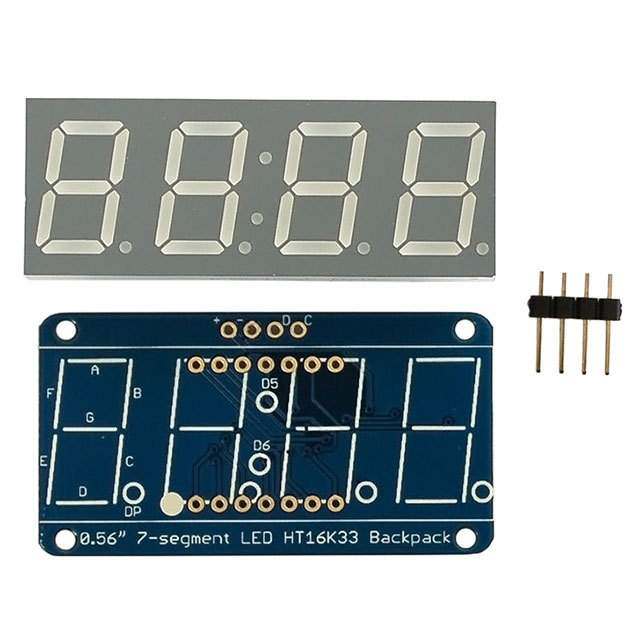
0.56" 7-Segment Backpack This version of the LED backpack is designed for these big bright 7-segment displays. These 7-segment displays normally require 13 pins (5 'characters' and 8 total segments each) This backpack solves the annoyance of using 13 pins or a bunch of chips by having an I2C constant-current matrix controller sit neatly on the back of the PCB. The controller chip takes care of everything, drawing all the LEDs in the background. All you have to do is write data to it using the 2-pin I2C interface. There are three address select pins so you can select one of 8 addresses to control up to 8 of these on a single 2-pin I2C bus (as well as whatever other I2C chips or sensors you like). The driver chip can 'dim' the entire display from 1/16 brightness up to full brightness in 1/16th steps. It cannot dim individual LEDs, only the entire display at once. When you buy a pack from Adafruit, it comes with the fully tested and assembled backpack as well as a 7- segment display in one of the colors we provide (say, red, yellow, blue or green). You'll need to solder the matrix onto the backpack but it's an easy task. Remove the parts from packaging and place the LED matrix OVER the silkscreen side. DO NOT PUT THE DISPLAY ON UPSIDE DOWN OR IT WONT WORK!! Check the image below to make sure the 'decimal point' dots are on the bottom, matching the silkscreen. © Adafruit Industries https://learn.adafruit.com/adafruit-led-backpack Page 29 of 74
Turn the backpack over so it is sitting flat on the matrix. Solder all 14 pins. © Adafruit Industries https://learn.adafruit.com/adafruit-led-backpack Page 30 of 74
Clip the long pins. Now you're ready to wire it up to a microcontroller. We'll assume you want to use a 4pin header. You can also of course solder wires directly. Place a 4-pin piece of header with the LONG pins down into the breadboard. © Adafruit Industries https://learn.adafruit.com/adafruit-led-backpack Page 31 of 74
Place the soldered backpack on top of the header and Solder 'em! That's it! now you're ready to run the firmware! Seven-Segment Backpack Firmware We wrote a basic library to help you work with the 7-segment backpack. The library is written for the Arduino and will work with any Arduino as it just uses the I2C pins. The code is very portable and can be easily adapted to any I2C- capable micro. Wiring to the matrix is really easy Connect CLK to the I2C clock - on Arduino UNO thats Analog #5, on the Leonardo it's Digital #3, on the Mega it's digital #21 Connect DAT to the I2C data - on Arduino UNO thats Analog #4, on the Leonardo it's Digital #2, on the Mega it's digital #20 Connect GND to common ground Connect VCC+ to power - 5V is best but 3V also seems to work for 3V microcontrollers. Next, download the Adafruit LED Backpack library from github (https://adafru.it/aLI) . To download click the DOWNLOADS button in the top right corner, rename the uncompressed folder Adafruit_LEDBackpack. Check that the Adafruit_LEDBackpack folder contains Adafruit_LEDBackpack.cpp and Adafruit_LEDBackpack.h Place the Adafruit_LEDBackpack library folder your arduinosketchfolder/libraries/ folder. You may need to create the libraries subfolder if it's your first library. You'll also need to download the Adafruit GFX library (https://adafru.it/aJa) - rename it Adafruit_GFX and install it as the LED backpack library. It's not actually used for the 7-segment, it's only for the matrix backpacks but it's still required. Restart the IDE. Once you've restarted you should be able to select the File?Examples?Adafruit_LEDBackpack?sevenseg example sketch. Upload it to your Arduino as usual. You should see a basic test program that goes through a bunch of different routines. © Adafruit Industries https://learn.adafruit.com/adafruit-led-backpack Page 32 of 74
Once you're happy that the matrix works, you can write your own sketches. There's a few ways you can draw to the display. The easiest is to just call print - just like you do with Serial print(variable,HEX) - this will print a hexidecimal number, from 0000 up to FFFF print(variable,DEC) or print(variable) - this will print a decimal integer, from 0000 up to 9999 If you need more control, you can call writeDigitNum(location, number) - this will write the number (0-9) to a single location. Location #0 is all the way to the left, location #2 is the colon dots so you probably want to skip it, location #4 is all the way to the right. If you want a decimal point, call writeDigitNum(location, number, true) which will paint the decimal point. To draw the colon, usedrawColon(true or false) If you want even more control, you can call writeDigitRaw(location,bitmask) to draw a raw 8-bit mask (as stored in a uint8_t) to that location. All the drawing routines only change the display memory kept by the Arduino. Don't forget to call writeDisplay() after drawing to 'save' the memory out to the matrix via I2C. There are also a few small routines that are special to the backpack: setBrightness(brightness)- will let you change the overall brightness of the entire display. 0 is least bright, 15 is brightest and is what is initialized by the display when you start blinkRate(rate) - You can blink the entire display. 0 is no blinking. 1, 2 or 3 is for display blinking. © Adafruit Industries https://learn.adafruit.com/adafruit-led-backpack Page 33 of 74
1.2" 7-segment Backpack These backpacks drive the massive 1.2" 7-segment modules. With 2 leds per segment these make a gorgeous and impressive display. The 7-segment displays normally require 16 pins to drive. This backpack uses an I2C constant- current matrix controller on the back of the PCB, so you only need 2 pins to drive it! The controller chip takes care of multiplexing all the LEDs in the background. All you have to do is write data to it using the 2-pin I2C interface. There are three address select pins so you can select one of 8 addresses to control up to 8 of these on a single 2-pin I2C bus (as well as whatever other I2C chips or sensors you like). The driver chip can 'dim' the entire display from 1/16 brightness up to full brightness in 1/16th steps. It cannot dim individual LEDs, only the entire display at once. When you buy a pack from Adafruit, it comes with the fully tested and assembled backpack as well as a 7- segment display in one of the colors we provide (say, red, yellow, blue or green). You'll need to solder the matrix onto the backpack but its an easy task. Remove the parts from packaging and place the LED matrix OVER the silkscreen side. DO NOT PUT THE DISPLAY ON UPSIDE DOWN OR IT WONT WORK!! Check the image below to make sure the 'decimal point' dots are in the same location as the ones on the silkscreen. © Adafruit Industries https://learn.adafruit.com/adafruit-led-backpack Page 34 of 74
Turn the backpack over so its sitting flat on the matrix and ready to solder. © Adafruit Industries https://learn.adafruit.com/adafruit-led-backpack Page 35 of 74
Then solder each pin. There are 8 on each end for a total of 16. That completes the basic assembly. For use on a breadboard, you will want to also install a 5-pin header on the edge of the board. © Adafruit Industries https://learn.adafruit.com/adafruit-led-backpack Page 36 of 74
Clip the long pins close to the board. Cut the header strip to length if necessary and insert LONG pins down into the breadboard. © Adafruit Industries https://learn.adafruit.com/adafruit-led-backpack Page 37 of 74
Then solder all 5 pins. Now you are ready to wire it to your microcontroller. The required connections are: "D" - I2C Data Pin (SDA) "C" - I2C Clock Pin (SCL) "+" - 5v. (Will not run on 3.3v!) "-" - GND "IO" - I2C bus voltage. Due to the size of this display, there are 2 LEDs in series for each segment. Because of this, the display requires 5v to run. It will not run on 3.3v. For use with 3.3v processors, connect the IO pin to 3.3v. This will keep the I2C bus signals at a safe level for your processor. With 5v processors like the Arduino UNO, this pin can be connected to either 5v or 3.3v. (use 3.3v if there will be other 3.3v devices on the bus) © Adafruit Industries https://learn.adafruit.com/adafruit-led-backpack Page 38 of 74
Arduino Wiring - R3 and later Connect: D -> SDA C -> SCL + -> 5v - -> GND IO -> jumper to + for 5v. Arduino Due and Other 3.3v Processors Connect: D -> SDA C -> SCL + -> 5v - -> GND IO -> 3.3v Arduino "Classic" Wiring Connect: D -> Analog-4 or Digital 20 for the Mega C -> Analog-5 or Digital 21 for the Mega + -> 5v - -> GND IO -> jumper to + for 5v. OK, now on to the firmware! Seven-Segment Backpack Firmware Our 7-segment backpack library makes it easy to program these displays. The library is written for the Arduino and will work with any Arduino as it just uses the I2C pins. The code is very portable and can be easily adapted to any I2C- capable micro. You can download the Adafruit LED Backpack library from github (https://adafru.it/aLI) . To download click the DOWNLOADS button in the top right corner, rename the uncompressed folder Adafruit_LEDBackpack. Check that the Adafruit_LEDBackpack folder contains Adafruit_LEDBackpack.cpp and Adafruit_LEDBackpack.h. If you need help with installing you libraries, we have a detailed guide here: © Adafruit Industries https://learn.adafruit.com/adafruit-led-backpack Page 39 of 74
https://adafru.it/aYM https://adafru.it/aYM You'll also need to download the Adafruit GFX library (https://adafru.it/aJa) - rename it Adafruit_GFX and install it as the LED backpack library. Close all open IDE windows and restart the IDE. Once you've restarted you should be able to select the File?Examples?Adafruit_LEDBackpack?sevenseg example sketch. Upload it to your Arduino as usual. You should see a "sevenseg" example sketch that will demonstrate various capabilities of the library and the display. Once you're happy that the matrix works, you can write your own sketches. There's a few ways you can draw to the display. The easiest is to just call print - just like you do with Serial print(variable,HEX) - this will print a hexidecimal number, from 0000 up to FFFF print(variable,DEC) or print(variable) - this will print a decimal integer, from 0000 up to 9999 If you need more control, you can call writeDigitNum(location, number) - this will write the number (0-9) to a single location. Location #0 is all the way to the left, location #2 is the colon dots so you probably want to skip it, location #4 is all the way to the right. To control the colon and decimal points, use the writeDigitRaw(location, bitmap) function. (Note that both dots of the center colon are wired together internal to the display, so it is not possible to address them separately.) Specify 2 for the location and the bits are mapped as follows: 0x02 - center colon (both dots) 0x04 - left colon - lower dot 0x08 - left colon - upper dot 0x10 - decimal point © Adafruit Industries https://learn.adafruit.com/adafruit-led-backpack Page 40 of 74
If you want a decimal point, call writeDigitNum(location, number, true) which will paint the decimal point. To draw the colon, use drawColon(true or false) If you want full control of the segments in all digits, you can call writeDigitRaw(location,bitmask) to draw a raw 8-bit mask (as stored in a uint8_t) to anylocation. All the drawing routines only change the display memory kept by the Arduino. Don't forget to call writeDisplay() after drawing to 'save' the memory out to the matrix via I2C. There are also a few small routines that are special to the backpack: setBrightness(brighness)- will let you change the overall brightness of the entire display. 0 is least bright, 15 is brightest and is what is initialized by the display when you start blinkRate(rate) - You can blink the entire display. 0 is no blinking. 1, 2 or 3 is for display blinking. © Adafruit Industries https://learn.adafruit.com/adafruit-led-backpack Page 41 of 74
Bi-Color 8x8 Matrix This version of the LED backpack is designed for these bright and colorful square=pixeled 8x8 matrices. They have 64 red and 64 green LEDs inside, for a total of 128 LEDs controlled as a 8x16 matrix. This backpack solves the annoyance of using 24 pins or a bunch of chips by having an I2C constant-current matrix controller sit neatly on the back of the PCB. The controller chip takes care of everything, drawing all 128 LEDs in the background. All you have to do is write data to it using the 2-pin I2C interface. There are three address select pins so you can select one of 8 addresses to control up to 8 of these on a single 2-pin I2C bus (as well as whatever other I2C chips or sensors you like). The driver chip can 'dim' the entire display from 1/16 brightness up to full brightness in 1/16th steps. It cannot dim individual LEDs, only the entire display at once. Pay close attention to the instructions for positioning the matrix. It must be oriented correctly to work and is almost impossible to remove it once it has been soldered to the backpack! © Adafruit Industries https://learn.adafruit.com/adafruit-led-backpack Page 42 of 74
When you buy a pack from Adafruit, it comes with the fully tested and assembled backpack as well as a 8x8 matrix. You'll need to solder the matrix onto the backpack but its an easy task. Remove the parts from packaging and place the LED matrix OVER the silkscreen side. The matrix must be soldered on the correct orientation or it will not work! Check for the side of the matrix that has printing on it. Then look for the front of the PCB that has a circle instead of a square in the corner and line those up as shown on the left Do not solder the matrix over the chip on the back of the backpack - it will not work then! © Adafruit Industries https://learn.adafruit.com/adafruit-led-backpack Page 43 of 74
Turn the backpack over so its sitting flat on the matrix. Solder all 24 pins. © Adafruit Industries https://learn.adafruit.com/adafruit-led-backpack Page 44 of 74
Clip the long pins © Adafruit Industries https://learn.adafruit.com/adafruit-led-backpack Page 45 of 74
Now you're ready to wire it up to a microcontroller. We'll assume you want to use a 4pin header. You can also of course solder wires directly. Place a 4-pin piece of header with the LONG pins down into the breadboard. Place the soldered backpack on top of the header. © Adafruit Industries https://learn.adafruit.com/adafruit-led-backpack Page 46 of 74
Solder 'em! Bi-Color 8x8 LED Backpack Firmware We wrote a basic library to help you work with the bi-color 8x8 matrix backpack. The library is written for the Arduino and will work with any Arduino as it just uses the I2C pins. The code is very portable and can be easily adapted to any I2C-capable micro. Wiring to the matrix is really easy Connect CLK to the I2C clock - on Arduino UNO thats Analog #5, on the Leonardo its Digital #3, on the Mega its digital #21 Connect DAT to the I2C data - on Arduino UNO thats Analog #4, on the Leonardo its Digital #2, on the Mega its digital #20 Connect GND to common ground Connect VCC+ to power - 5V is best but 3V also seems to work for 3V microcontrollers. Next, download the Adafruit LED Backpack library from github (https://adafru.it/aLI) . To download click the DOWNLOADS button in the top right corner, rename the uncompressed folder Adafruit_LEDBackpack. Check that the Adafruit_LEDBackpack folder contains Adafruit_LEDBackpack.cpp and Adafruit_LEDBackpack.h Place the Adafruit_LEDBackpack library folder your arduinosketchfolder/libraries/ folder. You may need to create the libraries subfolder if its your first library. You'll also need to download the Adafruit GFX library (https://adafru.it/aJa) that provides the graphics drawing routines. Restart the IDE. Once you've restarted you should be able to select the File->Examples->Adafruit_LEDBackpack->bicolor88 example sketch. Upload it to your Arduino as usual. You should see a basic test program that goes through a bunch of different drawing routines © Adafruit Industries https://learn.adafruit.com/adafruit-led-backpack Page 47 of 74
Once you're happy that the matrix works, you can write your own sketches. The 8x8 matrix supports everything the Adafruit GFX library - drawing pixels, lines, rectangles, circles, triangles, roundrects, and small bitmaps. For more details check out the GFX page which will detail all of the GFX routines (https://adafru.it/aPx). All the drawing routines only change the display memory kept by the Arduino. Don't forget to call writeDisplay() after drawing to 'save' the memory out to the matrix via I2C. There are also a few small routines that are special to the matrix: setBrightness(brightness)- will let you change the overall brightness of the entire display. 0 is least bright, 15 is brightest and is what is initialized by the display when you start blinkRate(rate) - You can blink the entire display. 0 is no blinking. 1, 2 or 3 is for display blinking. The default orientation for graphics commands on this display places pixel (0,0) at the top-left when the header is at the left and Adafruit logo at the right. To use the matrix as shown above (header at top, logo at bottom), call matrix.setRotation(3) before issuing graphics commands. © Adafruit Industries https://learn.adafruit.com/adafruit-led-backpack Page 48 of 74
Schematic © Adafruit Industries https://learn.adafruit.com/adafruit-led-backpack Page 49 of 74
Bi-Color 24 Bargraph This version of the LED backpack is designed for these bright and colorful bi-color bargraph modules. Each module has 12 red and 12 green LEDs inside, for a total of 24 LEDs controlled as a 1x12 matrix. We put two modules on each backpack for a 24-bar long bargraph (48 total LEDs). This backpack solves the annoyance of using lots of pins or a bunch of chips by having an I2C constant-current matrix controller sit neatly on the back of the PCB. The controller chip takes care of everything, drawing all 48 LEDs in the background. All you have to do is write data to it using the 2-pin I2C interface. There are three address select pins so you can select one of 8 addresses to control up to 8 of these on a single 2-pin I2C bus (as well as whatever other I2C chips or sensors you like). The driver chip can 'dim' the entire display from 1/16 brightness up to full brightness in 1/16th steps. It cannot dim individual LEDs, only the entire display at once. Attaching the bar-graph modules Pay close attention to the instructions for positioning the bargraphs. They must be oriented correctly to work and is almost impossible to remove them once soldered to the backpack! Remove the parts from packaging and place the LED bargraphs over the outlines on the top of the PCB. The bargraph must be soldered on the correct orientation or it will not work! Check for the side of the bargraph that has printing on it. Then look for the outline on the PCB that has "Text on this side" marked! Do not solder the matrix onto the back of the PCB, it won't work either! © Adafruit Industries https://learn.adafruit.com/adafruit-led-backpack Page 50 of 74
To keep the two bargraphs lined up nicely, you can use a little masking or scotch tape on the bargraph modules, tape them so they are in a straight line. There is a little play during soldering so if you don't do this the two modules may not be in a perfect line. © Adafruit Industries https://learn.adafruit.com/adafruit-led-backpack Page 51 of 74
Turn over the PCB and bend opposite-corner pins of the modules out so that the modules are fixed in place against the PCB. Now is a good time to do a last check that you oriented the modules the right way! Solder all the module pins in! © Adafruit Industries https://learn.adafruit.com/adafruit-led-backpack Page 52 of 74
OK nice work! © Adafruit Industries https://learn.adafruit.com/adafruit-led-backpack Page 53 of 74
Once soldered, clip each pin. They're quite short and the pins are thicker than usual, so do this over/inside a trash bin so that the pins don't fly off and it you or your pets. Everything should be neat and clipped, you're done! Soldering on breadboard pins This is an optional step - you only need to do this step if you're planning on using the bargraph in a breadboard. Chances are you may want to solder wires directly to the pads instead, so you can mount the bargraph elsewhere. Anyhow, skip this step if its not for you! © Adafruit Industries https://learn.adafruit.com/adafruit-led-backpack Page 54 of 74
Break off a piece of male header, 4 pins long. Plug the long ends into a solderless breadboard. Place the PCB on top. you may need to support it a little since its quite long. © Adafruit Industries https://learn.adafruit.com/adafruit-led-backpack Page 55 of 74
Solder these 4 pins too, since you're good at it now this should be easy. Bi-Color Bargraph LED Backpack Wiring & Firmware We wrote a basic library to help you work with the bi-color bargraph backpack. The library is written for the Arduino and will work with any Arduino as it just uses the I2C pins. The code is very portable and can be easily adapted to any I2C-capable micro. Wiring to the bargraph is really easy Connect SCL to the I2C clock - on Arduino UNO thats Analog #5, on the Leonardo its Digital #3, on the Mega its digital #21 Connect SDA to the I2C data - on Arduino UNO thats Analog #4, on the Leonardo its Digital #2, on the Mega its © Adafruit Industries https://learn.adafruit.com/adafruit-led-backpack Page 56 of 74
digital #20 Connect GND to common ground Connect VCC to power - 5V is best but 3V also seems to work for 3V microcontrollers. Next, download the Adafruit LED Backpack library from github (https://adafru.it/aLI) . To download click the DOWNLOADS button in the top right corner, rename the uncompressed folder Adafruit_LEDBackpack. Check that the Adafruit_LEDBackpack folder contains Adafruit_LEDBackpack.cpp and Adafruit_LEDBackpack.h Place the Adafruit_LEDBackpack library folder your arduinosketchfolder/libraries/ folder. You may need to create the libraries subfolder if its your first library. You'll also need to download the Adafruit GFX library (https://adafru.it/aJa) that provides the graphics drawing routines. Restart the IDE. Once you've restarted you should be able to select the File->Examples->Adafruit_LEDBackpack->bargraph24 example sketch. Upload it to your Arduino as usual. You should see a basic test program that tests all the LEDs with different colors © Adafruit Industries https://learn.adafruit.com/adafruit-led-backpack Page 57 of 74
Using the library interface is very easy. Start by creating the object with Adafruit_24bargraph bar = Adafruit_24bargraph(); you can name it whatever you want, not just bar Then initialize it with bar.begin(0x70); // pass in the address You can init with any address from 0x70 to 0x77, just make sure you solder in the matching solder jumpers! Finally, write to the bargraph with bar.setBar(lednumber, ledcolor); Where lednumber is 0 thru 23. ledcolor can be LED_RED, LED_YELLOW, LED_GREEN or LED_OFF The drawing routines only change the display memory kept by the Arduino. Don't forget to call bar.writeDisplay() after drawing to 'save' the memory out to the matrix via I2C. There are also a few small routines that are special to the matrix: setBrightness(brightness)- will let you change the overall brightness of the entire display. 0 is least bright, 15 is brightest and is what is initialized by the display when you start blinkRate(rate) - You can blink the entire display. 0 is no blinking. 1, 2 or 3 is for display blinking. © Adafruit Industries https://learn.adafruit.com/adafruit-led-backpack Page 58 of 74
Connecting Multiple Backpacks The coolest part about the I2C backpacks is that you can connect more than one using just the same 2 pins. This opens possibilities for all kinds of multi-display projects (https://adafru.it/aQt). For a project that shows this is practice, check out this page (https://adafru.it/aQF) on animating multiple LED backpacks Wire it Up To connect another backpack to your project, just wire it in parallel with the first one as in the diagram below. © Adafruit Industries https://learn.adafruit.com/adafruit-led-backpack Page 59 of 74
Configure the Address For each backpack you add, you need to configure a different I2C address. You can keep adding backpacks in the same way until you run out of addresses. See the next page for how to configure the address on your backpack. © Adafruit Industries https://learn.adafruit.com/adafruit-led-backpack Page 60 of 74
Changing I2C Address The HT16K33 driver chip on these LED backpacks has a default I2C address of 0x70. Since each device on an I2C bus must have a unique address, its important to avoid collisions or you'll get a lot of strange responses from your electronic devices! Luckily, the HT16K33 has 2 or 3 address adjust pins, so that the address can be changed! The mini 0.8" 8x8 matrix backpack has 2 address adjust pins. The 1.2" 8x8, bi-color 8x8, bi-color bargraph and 4 x 7-segment backpacks have 3 address adjust pins. That means that you can set the backpacks to these addresses: Mini 0.8" 8x8: 0x70, 0x71, 0x72, 0x73 Small 1.2" 8x8: 0x70, 0x71, 0x72, 0x73, 0x74, 0x75, 0x76, 0x77 4 x 7-segment: 0x70, 0x71, 0x72, 0x73, 0x74, 0x75, 0x76, 0x77 Bi-color 1.2" 8x8: 0x70, 0x71, 0x72, 0x73, 0x74, 0x75, 0x76, 0x77 Bi-color 24-bargraph: 0x70, 0x71, 0x72, 0x73, 0x74, 0x75, 0x76, 0x77 You can mix-and-match matrices, as long as each one has a unique address! Changing Addresses You can change the address of a backpack very easily. Look on the back to find the two or three A0, A1 or A2 solder jumpers. Each one of these is used to hardcode in the address. If a jumper is shorted with solder, that sets the address. A0 sets the lowest bit with a value of 1, A1 sets the middle bit with a value of 2 and A2 sets the high bit with a value of 4. The final address is 0x70 + A2 + A1 + A0. So for example if A2 is shorted and A0 is shorted, the address is 0x70 + 4 + 1 = 0x75. If only A1 is shorted, the address is 0x70 + 2 = 0x72 A2 does not appear on the mini 0.8" 8x8 matrix, so you cannot set the address higher than 0x73 On the 1.2" 8x8 backpacks, the labels for A1 and A2 are swapped! Sorry about that! © Adafruit Industries https://learn.adafruit.com/adafruit-led-backpack Page 61 of 74
Changing the address in your code Once you've adjusted the address on the backpack, you'll also want to adjust the address in the code! For the Arduino library we wrote, its simple. For example, lets say you want to have two seven-segment matrices. One is set to address 0x70 and the other is set to 0x71. Find this code in the example Adafruit_7segment matrix = Adafruit_7segment(); void setup() { Serial.begin(9600); Serial.println("7 Segment Backpack Test"); matrix.begin(0x70); } And change it to this: Adafruit_7segment matrix1 = Adafruit_7segment(); Adafruit_7segment matrix2 = Adafruit_7segment(); void setup() { Serial.begin(9600); Serial.println("Double 7 Segment Backpack Test"); matrix1.begin(0x70); matrix2.begin(0x71); } That is, instantiate two matrix objects. Then one is called with begin(0x70) and the other is called with begin(0x71). Each one can be used individually. If you need more matrices, just instantiate more objects at the top and begin() each one with the unique i2c address. © Adafruit Industries https://learn.adafruit.com/adafruit-led-backpack Page 62 of 74
© Adafruit Industries https://learn.adafruit.com/adafruit-led-backpack Page 63 of 74
F.A.Q. I want to use these modules with other non-Arduino, how can I port the code? The best way to get up and running is to read the HT16K33 driver datasheet available at http://learn.adafruit.com/adafruit-led-backpack/downloads - the backpacks all use this chip to do all the LED driving. You can cross-reference this document with the Arduino library code to adapt it to your platform. Any microcontroller that has I2C host support should be able to drive the backpacks but we only provide Arduino example code at this time I'd like to use these backpacks with Python / Linux (e.g. a Raspberry Pi) You're in luck! We have a full tutorial here that covers using the 7-segment and 8x8 matrices on a Pi with Python code -> http://learn.adafruit.com/matrix-7-segment-led-backpack-with-the-raspberry-pi I am having strange problems when combining Adafruit Motor Shield/Servo Shield (PCA9685 based) with the Adafruit LED Matrix/7Seg Backpacks We are not sure why this occurs but there is an address collision even though the address are different! Set the backpacks to address 0x71 or anything other than the default 0x70 to make the issue go away What is the current draw of the backpacks? It depends on how many LEDs you have lit at once! But a rough estimation is 20 milliamps per segment. Note that segments are multiplexed per row so that means 8x8 Mono Matrix (8 rows)= 8 x 20mA = 160mA max 7-segment backpacks (7 segments + 1 dot) = 8 x 20mA = 160 mA Alphanumeric (14 segments) = 14 x 20mA = 280mA Bi-color 8x8 and 8x16 matrix (16 rows) = 8 x 16 = 320mA But again, this is maximum and assumes all digits and all segments are lit up! Your average use may be 1/10 to 1/2 of this amount © Adafruit Industries https://learn.adafruit.com/adafruit-led-backpack Page 64 of 74
Downloads Software Download the Adafruit LED Backpack library from github (https://adafru.it/aLI) - This code provides support for the mini 8x8, 1.2" 8x8, 7-segment, bargraph, alphanumeric and bicolor LED matrix backpacks. To download click the ZIP download button, rename the uncompressed folder Adafruit_LEDBackpack. Check that the Adafruit_LEDBackpack folder contains Adafruit_LEDBackpack.cpp and Adafruit_LEDBackpack.h Place the Adafruit_LEDBackpack library folder your arduinosketchfolder/libraries/ folder. You may need to create the libraries subfolder if its your first library. You'll also need to download the Adafruit GFX library (https://adafru.it/aJa) - its not actually used for the 7-segment, its only for the matrix backpacks but its still required. Install just like the library above. Restart the IDE Files Fritzing objects in Adafruit Fritzing library (https://adafru.it/aP3) EagleCAD PCB files for all backpacks in GitHub (https://adafru.it/aLJ) The backpacks all use the HT16K33 chip solely for LED driving (https://adafru.it/aMy) - the mini 8x8's use the 24 pin version and the others use the 28 pin vesion HT16K33 8x16 LED Backpack Breakout Schematic & fabrication print © Adafruit Industries https://learn.adafruit.com/adafruit-led-backpack Page 65 of 74
8x8 0.8" LED Backpack © Adafruit Industries https://learn.adafruit.com/adafruit-led-backpack Page 66 of 74
8x8 1.2" LED Backpack © Adafruit Industries https://learn.adafruit.com/adafruit-led-backpack Page 67 of 74
8x8 1.2" Bi-Color LED Backpack © Adafruit Industries https://learn.adafruit.com/adafruit-led-backpack Page 68 of 74
16x8 1.2" LED Backpacks © Adafruit Industries https://learn.adafruit.com/adafruit-led-backpack Page 69 of 74
Quad 0.56" 7-Segment © Adafruit Industries https://learn.adafruit.com/adafruit-led-backpack Page 70 of 74
Quad 0.54" 14-segment Alphanumeric Quad 1.2" 7-Segment © Adafruit Industries https://learn.adafruit.com/adafruit-led-backpack Page 71 of 74
Bicolor 24-Bargraph © Adafruit Industries https://learn.adafruit.com/adafruit-led-backpack Page 72 of 74
© Adafruit Industries https://learn.adafruit.com/adafruit-led-backpack Page 73 of 74