
 Datasheet下载
- 型号: 81735512
- 制造商: Crouzet
- 库位|库存: xxxx|xxxx
- 要求:
| 数量阶梯 | 香港交货 | 国内含税 |
| +xxxx | $xxxx | ¥xxxx |
查看当月历史价格
查看今年历史价格
81735512产品简介:
ICGOO电子元器件商城为您提供81735512由Crouzet设计生产,在icgoo商城现货销售,并且可以通过原厂、代理商等渠道进行代购。 81735512价格参考。Crouzet81735512封装/规格:气动,液压, 3/2 Normally Closed Control Valve, Momentary Pushbutton Rod Mount。您可以下载81735512参考资料、Datasheet数据手册功能说明书,资料中有81735512 详细功能的应用电路图电压和使用方法及教程。
Crouzet品牌的型号81735512属于气动与液压控制系统中的压力开关,广泛应用于工业自动化领域。该型号主要用于监测和控制气动或液压系统中的压力变化,确保系统在安全、稳定的压力范围内运行。典型应用场景包括工业机械、自动化生产线、注塑机、包装设备、物料搬运系统以及测试设备等。

在气动系统中,81735512可用于压缩空气系统的压力监控,防止过压或欠压导致设备故障;在液压系统中,可对液压泵、油缸或阀门的压力进行实时检测,实现自动启停或报警功能。其高精度、可靠性和紧凑设计使其适用于空间受限但要求严苛的工业环境。

此外,该产品具备良好的抗振动和抗电磁干扰能力,适合在恶劣工业条件下长期稳定运行。常用于需要频繁压力控制和安全保护的场合,如机床、工程机械和自动化装配线。整体而言,81735512是一款适用于多种工业场景的耐用型压力控制元件。
| 参数 | 数值 |
| 产品目录 | 工业控制装置,量表 |
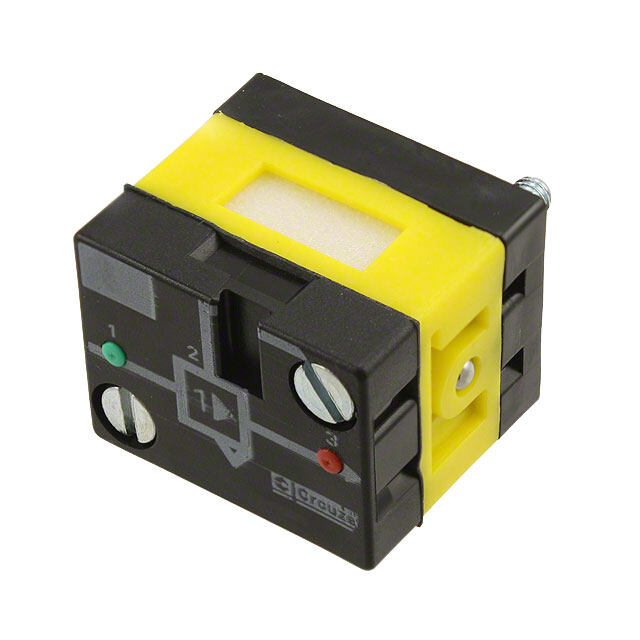
| 描述 | PNEUM VALVE ROUND PSHBTN RED NC |
| 产品分类 | 气动式 |
| 品牌 | Crouzet USA |
| 数据手册 | |
| 产品图片 |
|
| 产品型号 | 81735512 |
| rohs | 无铅 / 符合限制有害物质指令(RoHS)规范要求 |
| 产品系列 | * |
| 其它名称 | 81735512-ND |
| 其它有关文件 | |
| 标准包装 | 1 |


- 商务部:美国ITC正式对集成电路等产品启动337调查
- 曝三星4nm工艺存在良率问题 高通将骁龙8 Gen1或转产台积电
- 太阳诱电将投资9.5亿元在常州建新厂生产MLCC 预计2023年完工
- 英特尔发布欧洲新工厂建设计划 深化IDM 2.0 战略
- 台积电先进制程称霸业界 有大客户加持明年业绩稳了
- 达到5530亿美元!SIA预计今年全球半导体销售额将创下新高
- 英特尔拟将自动驾驶子公司Mobileye上市 估值或超500亿美元
- 三星加码芯片和SET,合并消费电子和移动部门,撤换高东真等 CEO
- 三星电子宣布重大人事变动 还合并消费电子和移动部门
- 海关总署:前11个月进口集成电路产品价值2.52万亿元 增长14.8%


PDF Datasheet 数据手册内容提取
WWW.CROUZET-CONTROL.COM PNEUMATICS PRODUCTS › Logic elements › Position / Detectors › Electro-pneumatic valves
| WWW.CROUZET-CONTROL.COM | 2 | PNEUMATICS PRODUCTS For over 50 years, Crouzet Control, has established a reputation for providing micro-control products, micro-motors and position sensors. Read on to discover Crouzet Control's complete offer of Pneumatic products for industrial and explosive atmospheres. Always one step ahead of market trends and customer requirements, Crouzet Control is continually developing its range of both standard and customised automation components and solutions to cover all the latest commercial and industrial applications and meet the needs expressed by manufacturers of automated equipment and machinery. Throughout the world, Crouzet Control the adaptation specialist provides you with technical and industrial expertise to ensure seamless integration, whatever the equipment environment or operating requirements of the machine. InnoVista Sensors™: your trusted partner of choice to face industrial challenges of today and tomorrow. InnoVista Sensors™ is a worldwide industrial specialist of sensors, controllers and actuators for automated systems. Through its brands, Crouzet Aerospace, Crouzet Automation, Crouzet Control, Crouzet Motors, Crouzet Switches and Systron Donner Inertial, InnoVista Sensors™ offers a wide range of reliable, efficient and customizable components dedicated to the Aerospace & Defence, Transportation and Industrial market and segments. Thanks to the recognized expertise of its teams and a strong innovation policy, InnoVista Sensors™ brings performance enhancing solutions to its customers worldwide. Eco-design is central to the company's "Offer Creation Process", the aim of which is to design products and services that correspond as closely as possible to customers' requirements and reduce their environmental impact throughout their life cycle. Customer satisfaction will always be our prime objective. To this end, we rely on standards ISO 9001 and ISO14001 to ensure that our design, industrialisation, manufacturing and commercialisation processes correspond to our customers' requirements. All Crouzet Control products are fully compliant with the RoHS directive
| WWW.CROUZET-CONTROL.COM | 3 | PNEUMATICS PRODUCTS Expertise - for all your applications Crouzet Control's Pneumatic expertise provides you with an offer to meet all your automation system requirements, including systems for explosive atmospheres. The quality of the Pneumatic components is based on a rigorous organisation which meets all current European and international directives, standards and approvals. All our products are fully compliant with the RoHS directive and embody an eco-design concept. The Pneumatic offer is the result of the implementation of Crouzet Control applications and expertise: v Listening to and analysing your requirements v Expertise in the associated applications: mechanical, electronic, sensors, etc. v Prototyping and industrialisation v Tests v Standardisation and certification (IEC, EN, UL-CSA, ATEX, etc.) v Equipment which is responsive and effective v International logistics and after sales support. Crouzet Control has developed broad expertise in ensuring that your specific needs are taken into account. Thanks to this expertise, we are continuously developing our standard products to create solutions tailored to your requirements. Some relevant areas Water treatment, chemical factories, silos, gas storage, ports, refineries, paper industry, paint factories, vehicles (if used in ATEX conditions), etc.
| WWW.CROUZET-CONTROL.COM | 4 | PNEUMATICS PRODUCTS Pneumatic offer for use in industrial and explosive atmospheres T his guide has been designed to help you quickly identify the appropriate products for your requirements.Most of our pneumatic components are available in a standard range and a range for use in explosive atmospheres (ATEX): this information is given in the right-hand column on each page. Industrial range The standard range of pneumatic components is designed to meet requirements for industrial applications. The operating characteristics (pressure, flow rate, service life, etc.) have been optimised to best meet these needs. Range for use in explosive atmospheres The range for use in explosive atmospheres has been developed specifically for applications requiring compliance with European Directive 94/9/EC, the full details of which can be found on pages 30 and 31 of this guide. The user is responsible for ensuring the compliance of his installations. All new installations must be compliant, and replacements in the event of breakdown or maintenance must comply with this directive. Characteristics of our ATEX components v ATEX products are specifically marked in accordance with the latest versions of harmonised standards v Every product is supplied with a guide specifying the usage restrictions in explosive atmospheres v A copy of the approval certificate can be provided if requested at the time of order v The order entry must state the usage conditions Crouzet Control states the usage restrictions on acknowledgements of receipt of order, delivery notes and invoices Crouzet Control has produced a separate catalogue for Pneumatic products for use in explosive atmospheres. This catalogue gives details of the entire Crouzet Control range of ATEX pneumatic products along with associated standards, certifications, directives, markings and order conditions.
| WWW.CROUZET-CONTROL.COM | 5 | PNEUMATICS PRODUCTS ATEX Directive 94/9/EC: general information Principles of Directive 94/9/EC: Application since 30 June 2003: The directive aims to harmonise the legislation of European Manufacturers must offer products, which comply with Directive Union member states in order to ensure free circulation of 94/9/EC and must have a Quality Control System that has been equipment intended for use in explosive atmospheres (gas and approved by a notified body. dust). Users are responsible for using equipment correctly according Since 1 July 2003, this directive has applied to electrical, mecha- to the zones they have defined within their installations based nical, hydraulic and pneumatic products. on the potential risks. Existing installations must be brought into It concerns the assessment of protective devices and systems conformity with the ATEX Directive before 30 June 2006. All (manufacturers) as well as the design (design office), installa- new products commissioned must comply with Directive 94/9/ tion (installers, panel-builders) and maintenance (maintenance EC. In the event of breakdown, installed equipment that cannot depts) of installations. be repaired must be replaced with equipment complying with Directive 94/9/EC Definition of an explosive atmosphere: Classification: An explosive atmosphere is defined as a mixture of flammable substances (in the form of gas, vapour, mist or dust) with air Potentially explosive environments are classified by zone in under atmospheric conditions in which, after ignition, combustion compliance with Directive 1999/92/EC. This directive is aimed spreads throughout the entire unburned mixture. at users. It details the minimum requirements for increasing protection of the health and safety of workers exposed to explosive atmospheres. Sparks Heat source ATEX Directive 94/9/EC defines categories of equipment and protection systems, which can be used in the corresponding zones. Categories M1 and M2 relate to mines (group I) Categories 1, 2 and 3 relate to other locations (group II) often referred to as "Surface industries" Documents and recommendations/products: ATEX-certified products must be supplied with an EC declaration of conformity and a user manual. At the time of sale, the sales representatives must check the zone in which the product is to be used. On the order, the customer Oxidiser Fuel must inform the manufacturer of the conditions of use. Oxygen (air contains Flammable substances in the Manufacturers and distributors must ensure that their sales of 21% oxygen) form of gas, vapour, mist, dust ATEX products are traceable (so that customers who have been sold an ATEX product can be located in relation to the product's date of manufacture). In the case of an assembly, the product with the lowest certifica- Some relevant areas: tion level determines the level of the whole assembly. Silos Water treatment Ports Refineries Paper industry Gas storage Paint factories Vehicles (if used in ATEX conditions) Chemical factories
| WWW.CROUZET-CONTROL.COM | 6 | PNEUMATICS PRODUCTS Equipment definition: Equipment for surface industry - Group II Zone 0 20 1 21 2 22 Type of atmosphere G D G D G D G = Gas, D = Dust Continuous presence Intermittent presence Fleeting presence Presence of Explosive (or for long periods, i.e. more than (or occasional, i.e. 10 to 1000 (or rare, i.e. 1 to 10 hours per atmosphere 1000 hours per year) hours per year) year) Category of equipment that can be used 1 2 3 as per 94/9/EC dated 23/03/94 Marking example: Certified products must incorporate marking specific to Directive 94/9/EC, such as: Crouzet Automatismes SAS 2 rue du Docteur Abel, 26902 Valence, FRANCE Type: 81513530 Serial no: Year of construction CE 0081 II 1 G Ex ia II C T6 LCIE 02 ATEX 6121 X Max. amb. T: +50°C Explanation of the marking example: The CE marking along with the identification number of The CE-Type Examination Certificate reference (if appro- the notified body responsible for monitoring the QCS priate). (0081 = LCIE). LCIE 02 ATEX 6121 X CE 0081 II 1 G Max. amb. T: +50°C The symbol indicating that this product can be used The ambient operating temperature range. in an explosive atmosphere followed by the equipment group (II = Surface Industries), the category (1 = continuous presence; 2 = intermittent presence; In the event of use in an explosive atmosphere caused by dust, 3 = fleeting presence), and the type of explosive the following items are added to the marking: atmosphere G = Gas, D = Dust. In affixing this CE marking, the manufacturer declares that the The surface limit temperature T° C for use in an explosive product has been manufactured in complete conformity with the atmosphere caused by dust. requirements of all the relevant directives. The IP rating (only for dust) Next line of the marking specified by the harmonised standards: Ex ia II C T6 X Reference to the operating instructions for the product Temperature Class corresponding to a max. surface temperature of 85°C Subdivision IIC: including hydrogen acetylene in particular, carbon bisulfur Protection method used: intrinsic safety Symbol indicating that the equipment complies with one or more protection methods
| WWW.CROUZET-CONTROL.COM | 7 | PNEUMATICS PRODUCTS Examples of applications: Medical mattress Microporous textile Pressure zones Electrical control Solenoid valves Air supply Control console Textile machine Worked yarn Weaving unit Process control Yarn processing modules To yarn processing module Pneumatic solenoid valves Unprocessed yarn Industrial valve Electronic valve Air supply Exhaust Open/close flow control Pneumatic actuators for quarter-turn or proportional taps and valves allow open/close commands and flow rate changes to be automated. The pneumatic actuating cylinder is operated by means of an air distributor valve built into the valve body and controlled by a solenoid valve.
| WWW.CROUZET-CONTROL.COM | 8 | PNEUMATICS PRODUCTS Marking control system S emi-automatic resin filling system, with anti-drip control Automatic assembly system
| WWW.CROUZET-CONTROL.COM | 9 | PNEUMATICS PRODUCTS Particular realizations Component on manifold mastered Solenoid valves on manifold System for inflating Valves modules on manifold For others configurations, consult us
| WWW.CROUZET-CONTROL.COM | 10 | PNEUMATICS PRODUCTS General summary Pages 11 Manual actuated valves 21 Position detectors 35 Pressure switches - Vacuum 41 Pneumatic logic components 57 Electro-pneumatic control valves 69 Multi-fluid solenoid valves 72 Teaching materials
| WWW.CROUZET-CONTROL.COM | 11 | PNEUMATICS PRODUCTS Pages MANUAL ACTUATED VALVES 11 21 35 41 57 69 72
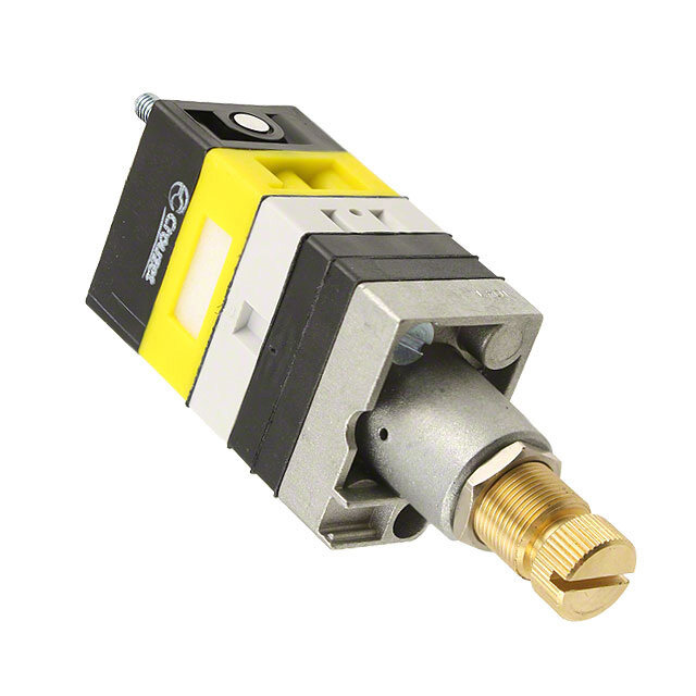
| WWW.CROUZET-CONTROL.COM | 12 | PNEUMATICS PRODUCTS Push buttons diameter 12 and actuators Actuator Valve Push button Push button Features color color round double round Version black black 81 735 511 - NC red black 81 735 512 - black/red black - 81 733 511 black grey 81 735 011 - N0 red grey - - black/red grey - - Symbol NC NO Characteristics Operating pressure bar 2 ➞ 8 2 ➞ 8 Orifice diameter mm 2.7 2.7 Flow at 6 bars Nl/mn. 200 200 NC : black l l Valves NO : grey l Operating forces (depending on actuator) N 8 ➞ 18 8 ➞ 18 Effective travel mm 1 1 Fluid: dry or lubricated air l l Push-in connectors for semi-rigid tubing mm Ø 4 Ø 4 (NFE 49100) Operating temperature °C -5 ➞ +50 -5 ➞ +50 Mechanical life operations 1.5 x 10⁶ 1.5 x 10⁶ Weight g 35 40 Dimensions 81 735 81 733 Threaded barrel 2 threaded barrels
| WWW.CROUZET-CONTROL.COM | 13 | PNEUMATICS PRODUCTS 3-position lever 3-position lever Horizontal outputs Vertical outputs manual return spring return 81 716 511 81 715 511 81 280 510 81 281 510 81 716 512 81 715 512 - - - - - - - - 81 280 010 81 281 010 - - - - - - - - 2 ➞ 8 2 ➞ 8 2 ➞ 8 2 ➞ 8 2.7 2.7 2.7 2.7 200 200 200 200 l l - - l l - - 8 ➞ 18 8 ➞ 18 - - 1 1 1 1 l l - - Ø 4 Ø 4 Ø 4 Ø 4 -5 ➞ +50 -5 ➞ +50 -5 ➞ +50 -5 ➞ +50 1.5 x 10⁶ 1.5 x 10⁶ 1.5 x 10⁶ 1.5 x 10⁶ 65 65 14 14 81 715 - 81 716 81 280 010 - 81 280 510 Square lever 81 281 010 - 81 281 510 M3 28,5
| WWW.CROUZET-CONTROL.COM | 14 | PNEUMATICS PRODUCTS 3/2 valves for manual actuators Ø 22 mm 3/2 valve supplied with screws Connection Ø4 89 543 501 89 543 101 - - - - - for fixing the adaptator Gas 1/8 89 543 701 89 543 201 - - - - - Valve(s) 3/2 fixed on adaptator Connection Ø4 - - 89 543 105 89 543 005 89 543 305 89 543 205 - (supplied with adaptator not assembled) Adaptator for 3/2 valve on actuators Ø 22 - - - - - - 24 679 702 Version NC NO NC NO NC + NO NC + NC Symbol Characteristics Operating pressure bar 0 ➞ 8 0 ➞ 8 0 ➞ 8 0 ➞ 8 0 ➞ 8 0 ➞ 8 - Orifice diameter mm 2 2 2 2 2 2 - Flow at 6 bars NI/min 112 112 112 112 112 112 - Control force N 12.6 12.6 12.6 12.6 12.6 12.6 - Operating temperature in dry air °C -5 ➞ +60 -5 ➞ +60 -5 ➞ +60 -5 ➞ +60 -5 ➞ +60 -5 ➞ +60 - Life operations 1.5 x 10⁶ 1.5 x 10⁶ 1.5 x 10⁶ 1.5 x 10⁶ 1.5 x 10⁶ 1.5 x 10⁶ - Non-connectable exhaust l l l l l l - Weight g 50 50 60 60 110 110 40 Principle of operation Dimensions Ø 22 series NC version 89 543 001 - 89 543 201 89 543 501 - 89 543 701 Exhaust 2 0, 4 60 1 2 Supply Output Holes drilled in panel for actuators Ø 22 Installation EN 50007 46,5 32 Holes drilled for the (optional) use of a round lug. * > 40 Ø 40 push-buttons * > 45 for lever type rotary switches
| WWW.CROUZET-CONTROL.COM | 15 | PNEUMATICS PRODUCTS Actuators Ø 22 mm for manually operated valves Red 24 678 129 24 678 173 24 678 171 - - Push buttons Green 24 678 128 - - - - Black 24 678 127 24 678 172 - - - 2-positions rotary switches - - - 24 678 174 24 678 175 3-positions rotary switches - - - - - Function Flush push Emergency stop Emergency stop Black symmetrical Long lever Black contact plastic Ø 40 Ø 40 mm push- actuator turn Symbol Position 45° 45° Weight g 30 45 45 45 45 Dimensions 24 678 127 - 24 678 128 24 678 171 - 24 678 172 24 678 129 Ø 29 24 678 173 Ø 40 5 3, 1 5 4, 3 2-positions rotary switches 24 678 180 - 3-positions rotary switches - 24 678 176 24 678 178 24 678 177 24 678 179 24 678 182 24 678 181 Function RONIS key 455 Black symme- Black symme- Long lever Black Long RONIS key RONIS key removable in trical actuator trical actuator Black lever, spring to 455 remov. 455 removable position 0 with return center in pos. 0 in position 0 3 positions with 3 fixed spring to center positions Symbol Position 45° 2 x 45° 2 x 45° 2 x 45° 2 x 45° 2 x 45° 2 x 90° W eight 70 45 45 16 45 70 70 Dimensions 24 678 174 - 24 678 176 24 678 175 - 24 678 177 24 678 180 - 24 678 181 24 678 178 Ø 30 24 678 179 38,3 24 678 182 Ø 29 27,3 27 23 7 2 9 2 Désignation : Référence : 24 679 171 / 24 679 172 / 24 679 173 SODIPE DESSINE PAR DPH 004 186 P2
| WWW.CROUZET-CONTROL.COM | 16 | PNEUMATICS PRODUCTS MCaochnifnoermrys D toir etchteiv e Definition (conforming to EN 574 +A1) A pneumatic 2-hand control device is used with dangerous machinery and requires the simultaneous use of both hands to trigger and maintain machine operation. Such a device must be located outside the dangerous zone, so that the operaPtor cnannoet enuter tmhis zonae betfoire sthe cmachhinee has coZme wto a ceompilehte staandsntill. dsteuerung A pneumatic 2-hand control device is composed of 2 parts : ■ 2 manual pushbuttons which require the simultaneous use of both hands. ■ A pneumatic relay. Types of 2-hand control devices Type Requirements III I II A B C Use of both hands (simultaneous actuation) l l l l l Relationship between input signals and l l l l l output signal Cessation of the output signal l l l l l Prevention of accidental operation l l l l l Prevention of defeat l l l l l Reinitiation of the output signal l l l l Synchronous actuation l l l Use of category 1 (EN 954-1) l l Use of category 3 (EN 954-1) l l Use of category 4 (EN 954-1) l Category 1 (EN ISO 13849) : the system should use well tried components and principles. Category 3 (EN ISO 13849) : the system must be designed so that a single fault will not cause the loss of the safety function. Category 4 (EN ISO 13849): the system must be designed so that an accumulation of faults must not lead to a loss of the safety function. Synchronous action An output signal is only generated if both control actuating devices are actuated within 500 ms. Resetting the output signal The release of a single control device interrupts the output signal, but a reset is only possible once both control devices have been released.
| WWW.CROUZET-CONTROL.COM | 17 | PNEUMATICS PRODUCTS Pneumatic relay for two-hand control › 100% pneumatic › Complies with Machinery Directive and the standard EN 574 +A1 › CE Certification type-IIIA and IIIB Pneumatic relay for two-hand control 81 580 101 81 580 202 EN 574 +A1 classification III A III B Symbol 1 3 1 2 Characteristics Operating pressure bar 2 ➞ 8 2 ➞ 8 Orifice diameter mm 2.5 2.5 Max. delay between input signals s 0.2 max. 0.2 max. Connection Sub-base 81 532 001 Semi-rigid tubing Ø 4 (NFE 49100) Operating temperature °C -5 ➞ +50 -5 ➞ +50 Mechanical life operations 107 107 Weight g 90 320 Principle of operation Connections (Typical application with double-acting cylinder) 81 580 101 81 580 101 81 580 202 1 81 580 101 81 580 202 Components follow current standards 6 7 To obtain an output signal it is necessary to give simultaneous input signals 'a' and 'b' with a max. delay of 0.45. The output signal 's' is lost if one or both of the inputs are removed. Dimensions 81 58M04 101 81 580 202 34,5 64 2 3 3 2 15 6 7 25 7 5, 0,5 12 1 Pb SbPb Sb M4 Pa SaPb Sb Mounted on sub-base 81 532 001 2 3 (See page 55 of Pneumatic catalogue) 32 23 21,2245 2 x M4 Depth 10 15 25
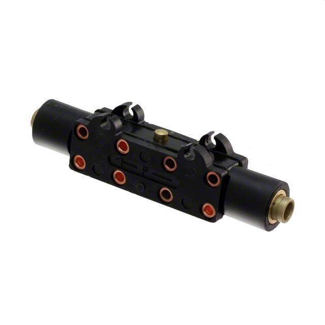
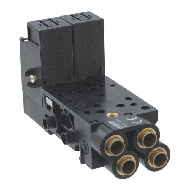
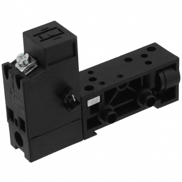
| WWW.CROUZET-CONTROL.COM | 18 | PNEUMATICS PRODUCTS Two-hand pneumatic safety start module › Conforms to the Machinery Directive and standard EN 574 › Including pneumatic relay to classification IIIA or IIIB depending on version Two-hand pneumatic safety start module 81 580 504 81 580 503 Pneumatic relay (to EN 574) Type III A Type III B Symbol S S P P Characteristics Operating pressure bar 2 ➞ 8 2 ➞ 8 Orifice diameter mm 2.5 2.5 Max. delay between input signals s 0.2 max. 0.2 max. Connection Semi-rigid tubing Ø 4 (NFE 49100) Semi-rigid tubing Ø 4 (NFE 49100) Operating temperature °C -5 ➞ +50 -5 ➞ +50 Mechanical life operations 1.5 x 10⁶ 1.5 x 10⁶ Weight g 1000 1410 Connections (Typical application with double-acting cylinder) 81 580 504 81 580 503 P S P S 1 81 580 504 81 580 503 Components follow current standards Dimensions 81 580 503 - 81 580 504 Supply via 4 mm Output via 4 mm push-in fitting push-in fitting Fixing viewed from below
| WWW.CROUZET-CONTROL.COM | 19 | PNEUMATICS PRODUCTS Pneumatic impulse counters › 4, 5, 6 digits with or without reset › With or without pre-selection Totalizer 99 766 001 99 766 002 - Preselection counter - - 89 538 201 Version 6 digits no reset 4 digits with 5 digits with to zero manual zero reset manual or pneu- matic zero reset Symbol Characteristics Supply pressure bar 2 ➞ 8 2 ➞ 8 2 ➞ 8 Pressure to break bar > 0.3 > 0.3 > 0.15 Pressure to make bar > 1.4 > 1.4 > 0.8 Reset : Minimum pressure bar - - 2 Reset time ms - - 150 Circuit pressure - - 2 ➞ 8 bar - - l Signal emitted when preset is reached 0 ➞ +60 0 ➞ +60 0 ➞ +60 Operating temperature °C 150 150 136 Weight - g A - Output signal P - Supply Connection Y - 'Reset to zero' signal Z - Input signal Note : the count pulse must be removed before the reset pulse is applied. The pre- set value can be changed during operation without the counter resetting to zero. Dimensions Connectors for semi-rigid tubing Ø 4 (NFE 49100) 99 766 002 89 538 201 48 14,5 22 x 33,3 5,3 48 14,5 22 x 33,3 5,3 Ø 3.2 f/90° 2 holes for M3 screws = 24= Ø 30,20 F0/090 Ø 4 24==2 0000 3Ø 4 = 41,5 = Ø 36,20 ,F6/90 2 3 = 41,5 = 60,6 99 766 001 48 14,5 22 x 33,3 = 3 2 = == 23 24== 00037000 = Ø 4M3 = M3 Ø 3,24 1F,/590 2= 37 = 3 = 41,5 = 6401,6,5 = 3 2 = M3 = 37 = 41,5
| WWW.CROUZET-CONTROL.COM | 20 | PNEUMATICS PRODUCTS Indicators and pedal valves › Ergonomics Also available in ATEX version for use in poten- tially explosive atmospheres in accordance with 94/9/EC Directive Pneumatic indicators Ø 22 Red 84 150 201 - Green 84 150 202 - Yellow 84 150 203 - Blue 84 150 204 - Pedal valve - Version NC - 81 999 501 Symbol Characteristics Operating pressure bar 2 ➞ 8 - Push-in connection for semi-rigid tubing mm Ø4 Ø4 (NFE 49100) Operating temperature °C -5 ➞ +50 -5 ➞ +50 Mechanical life operations 107 1.5 x 10⁶ Weight g 34 290 Dimensions 84 150 201 - 84 150 202 81 999 501 84 150 203 - 84 150 204 White tube Input Output Red tube Holes drilled for indicators ATEX version products are available in the following catologues: Pneumatic products for explosive atmospheres or on our website www.crouzet-control.com
| WWW.CROUZET-CONTROL.COM | 21 | PNEUMATICS PRODUCTS POSITION DETECTORS
| WWW.CROUZET-CONTROL.COM | 22 | PNEUMATICS PRODUCTS Pressure decay sensor › 100 % pneumatic Also available in ATEX version for use in poten- tially explosive atmospheres in accordance with 94/9/EC Directive Pressure decay sensor 81 504 025 Symbol Characteristics Operating pressure bar 2 ➞ 8 Flow at 6 bars NI/min 200 Tripping point b 0.3 with 6 bar supply Connection Sub-base page 54-55 Operating temperature °C -5 ➞ +50 Mechanical life operations ≥107 Weight g 25 Connections Without flow restrictor With flow restrictor Signal when Signal cylinder when is in cylinder is out Principle of operation Evolution of pressure within a double-acting cylinder Fitted in-line between the cylinder and the control valve, the sensor will give an output Pressure when the pressure in this line is exhausted in the cylinder and the cylinder is at end of stroke. Cpriercsusiut re Working pres- For the correct usage of sensors on a falling sure pressure, it is recommended that the practical cylinder load is limited to 60% of the theore- Operation of tical force. Pdirfefesrseunrcee tfahlel isne pnrseosrs ounre a Exhaust pressure Creyslpinodnesre time Cylindtimere travel Time Control valve Starting point End of stroke changeover of cylinder Dimensions 81 504 025 ATEX version products are available in the following catologues: Pneumatic products for explosive atmospheres or on our website www.crouzet-control.com
| WWW.CROUZET-CONTROL.COM | 23 | PNEUMATICS PRODUCTS Low force position detector › 100 % pneumatic › Conforme à la nore DIN 41365 Forme A › Faible effort d'actionnement < 50 g à 6 bars › Pas de consommation permanente d'air comprimé Also available in ATEX version for use in poten- tially explosive atmospheres in accordance with 94/9/EC Directive Function NO 81 290 501 - NC - 81 290 001 Symbol Characteristics Orifice diameter mm 2 2 Operating pressure bar 3 ➞ 8 3 ➞ 8 Flow at 4 bars NI/min 100 100 Activation force at 6 bars N < 0,5 < 0,5 Permissible fluids (air / inert gas) l l Max/min of fluid °C -10 ➞ +50 -10 ➞ +50 temperatures operating °C -10 ➞ +60 -10 ➞ +60 storage °C -40 ➞ +70 -40 ➞ +70 Mechanical life at 6 bars operation 107 107 Response on activation ms ≤ 15 ≤ 15 time on release ms ≤ 15 ≤ 15 Barb connection for semi-rigid tubing 2.7 x 4 2.7 x 4 Weight g 8.5 8.5 Principle of operation NC Desactivated Activated S (2) (1) Operation accessories Unless otherwise requested, flat and roller-ended levers 161 A 161 E are supplied loose. flat R 25.4 with roller R 24.1 70 507 524 70 507 529 Dimensions 161 A 161 E 2020DI11.8511.8N ØØ10.3410.3331++++0000..6..10103.23.255553533 ..F88orm A3300 Total travel2.5 Course totale2.5 Course totale 0.50.5Tripping point14.7Position d'action14.7Position d'action Position reposRest point16Position repos16 16.516.5 ±0.24.3R 25.42. 4±0,2 ±0.24.3 R 2.4 R R R 243.4.1 ±60.R,3 2 8 3.4Ø4.8 6.3 8 Ø4.8 55.8 12.95 33..44 +0.15+0.1533+0.05+0.05 5.8 122.925.2 22.2 10.710.7 3.9 3.9 ATEX version products are available in the following catologues: Pneumatic products for explosive atmospheres or on our website www.crouzet-control.com
| WWW.CROUZET-CONTROL.COM | 24 | PNEUMATICS PRODUCTS “Microvalve” series position detectors › 100 % pneumatic 81 280 81 281 Version NO 81 280 010 81 281 010 - NC 81 280 510 81 281 510 81 283 510 Features Horizontal output Vertical output Rear connection by screw Symbol NO NC Characteristics Operating pressure bar 2 → 8 2 → 8 2 → 8 Orifice diameter mm 2.7 2.7 Flow at 6 bars NI/min 200 200 138 Operating force at 6 bars N 15 15 15 Effective travel mm 1 1 1 Push-in connection for mm Ø 4 Ø 4 Ø 4 semi-rigid tubing (NFE 49100) Operating temperature °C -5 ➞ +50 -5 ➞ +50 -5 ➞ +50 Mechanical life operat. 5 x 10⁶ 5 x 10⁶ 5 x 10⁶ Weight g 14 14 20 Principle of operation NC NO C T F A R R P P P P Actuation positions : PFC : End of travel position PA : Operating position (max output kV) PRT : Release position (max. exhaust kV) PR : Rest position Dimensions 81 281 010 - 81 281 510 81 280 010 - 81 280 510 81 283 510 o 2 5, 11,511,5 002645P2
| WWW.CROUZET-CONTROL.COM | 25 | PNEUMATICS PRODUCTS “Microvalve” series position detectors › 100 % pneumatic Features Short lever With ball Roller trip With roller Threaded barrel Ø 16 Plunger Version NC Vertical output 81 281 502 81 281 504 81 281 508 81 281 509 81 737 501 Symbol Characteristics Operating pressure bar 2 → 8 2 → 8 2 → 8 2 → 8 2 → 8 Orifice diameter mm 2.7 2.7 2.7 2.7 2.7 Flow at 6 bars NI/min 200 200 200 200 200 Operating force at 6 bars N 15 15 15 15 25 Effective travel mm 1 1 1 1 1 Push-in connection for mm Ø 4 Ø 4 Ø 4 Ø 4 Ø 4 semi-rigid tubing (NFE 49100) Operating temperature °C -5 ➞ +50 -5 ➞ +50 -5 ➞ +50 -5 ➞ +50 -5 ➞ +50 Mechanical life operat. 5 x 10⁶ 5 x 10⁶ 5 x 10⁶ 5 x 10⁶ 5 x 10⁶ Weight g 16 18 18 18 90 Dimensions 81 281 502 81 281 504 81 281 508 Ball Ø 9 R R R P P P 81 281 509 81 737 501 at apacity m across fl ng c 1 m R PR Max. fixi18 mm 2 nuts 2 P APRct u: aRteiosnt p poossitiiotinons : R P
| WWW.CROUZET-CONTROL.COM | 26 | PNEUMATICS PRODUCTS "Miniature" series position detectors › 100 % pneumatic › All metal Part numbers Version Push-in connection for semi-rigid tubing (NFE 49100) Ø 4 silenced exhaust 81 921 501 81 921 701 81 921 702 81 921 707 M5 connectable exhaust - - - - N C Ø 4 connectable exhaust * - - - - Ø 6 connectable exhaust * - - - - Ø 4 silenced exhaust - - - - NO Ø 6 silenced exhaust - - - - Control Simple plunger Lever with plastic Lever with roller Lever with one-way roller bearing trip plastic roller Symbol NC NC NC Characteristics Operating pressure bar 0.1 → 8 0.1 → 8 0.1 → 8 0.1 → 8 Orifice diameter mm 2.7 2.7 2.7 2.7 Flow at 6 bars NI/min 200 200 200 200 Actuation force at 6 bars N 18 18 18 18 Circuit function : NC l l l l Circuit function: NO - - - - Connectable exhaust Operating temperature °C -5 ➞ +50 -5 ➞ +50 -5 ➞ +50 -5 ➞ +50 Mechanical life operations ≥107 ≥107 ≥107 ≥107 Weight g 62 75 80 77 Principle of operation Actuation travel NC NO Vertical attack Simple plunger Exhaust Actuation positions : PA : Operating position (max output kV) Poppet PFC : End of travel position PO : Mid-position closed (no exhaust, no outlet) PRT : Release position PR = PFC = PA = PO = PRT = PR : (Rmeasxt peoxshiatiuosnt kV) Dimensions 81 921 501 81 921 701 - 81 921 702 81 921 707 * with barb for tube Ø 2.7 x 4 Material: body zamak
| WWW.CROUZET-CONTROL.COM | 27 | PNEUMATICS PRODUCTS - - - - - 81 921 806 - - - - 81 921 714 - - - - 81 921 719 81 921 717 - - 81 921 911 81 921 912 - - 81 921 901 81 921 902 Lever with plastic Lever with roller Lever with plastic Lever with roller roller bearing roller bearing NC NC NO 0.1 → 8 0.1 → 8 0.1 → 8 0.1 → 8 2.7 2.7 2.7 2.7 200 200 200 200 18 18 18 18 l l l l - - l l l l -5 ➞ +50 -5 ➞ +50 -5 ➞ +50 -5 ➞ +50 ≥107 ≥107 ≥107 ≥107 75 80 100 100 Horizontal actuating 30° cam (other angles of attack are also possible, 45° even 90°). With lever With lever With lever One-way trip lever PA = PO = PA = PRT = PRT = PO = PO = PRT = PA = PR = PFC = PA = PO = PRT = Hatotariczko natrael aalcstou aptoinsgs i3bl0e°, c4a5m° e(voethne 9r 0a°n).gles of PR = PR = 81 921 806 81 921 714 81 921 717 - 81 921 719 81 921 901 - 81 921 902 6 81 921 911 - 81 921 912 6 2 5 4, 4 5 5, 2 36 13 Material: body zamak Other configuration on demand Désignation : Pneumatique Référence : 81921714/81921717/81921719 001 539 P2 SODIPE DESSINE PAR ST
| WWW.CROUZET-CONTROL.COM | 28 | PNEUMATICS PRODUCTS "Compact” series position detectors › 100 % pneumatic › All metal Part numbers Features Direct acting Rotary actuator Rotary actuator Rotary actuator 81 922 401 81 922 205 81 922 010 81 922 210 Version Roller plunger with Right-hand rotary Programmable Programmable unthreaded barrel head with roller rotary head wit- rotary head wit- lever (CNOMO) hout lever hout lever Symbol Characteristics BSP - 1/8 - 1/8 Connection push-in for semi-rigid tubing mm Ø 4 - Ø 4 - (NFE 49100) Operating pressure bar 0.1 → 8 0.1 → 8 0.1 → 8 0.1 → 8 Bore diameter mm 3 3 3 3 Flow at 6 bars Nm3/h 200 200 200 200 Activation force at 6 bars daN 2.5 2.5 2.5 2.5 Circuit function: NC l l l l Mechanical life operations > 107 > 107 > 107 > 107 Silenced or connectable (1/8) exhaust l l l l Operating temperature °C -5 ➞ +50 -5 ➞ +50 -5 ➞ +50 -5 ➞ +50 Weight g 150 193 175 175 Accessories plastic 79 452 103 - l l l Lever with roller bearing 79 452 104 - l l l Lever with adjustable plastic 79 452 123 - l l l roller bearing 79 452 124 - l l l Adjustable steel rod lever 79 452 133 - l l l Principle of operation Exhaust 2 S Poppet 1 Vertical attack Horizontal attack Detectors with roller plunger with unthreaded barrel. Detectors with roller plunger with unthreaded barrel. PRT PO PA Line of attack Actuation positions : R RT O A FC PA : Operating position (max output kV) P P P P P PFC : End of travel position PO : Mid-position closed (no exhaust, no outlet) PRT : Release position (max exhaust kV) PR : Rest position The detectors 81 922 010 and 81 922 210 can operate to both left and right. Material: body zamak Other configuration on demand Désignation : Référence : 001 642 P5 SODIPE DESSINE PAR DPH
| WWW.CROUZET-CONTROL.COM | 29 | PNEUMATICS PRODUCTS Rotary actuator Detectors with levers 81 922 - 81 922 0 - 81 922 2 Dimensions 81 922 401 79 452 123 - 79 452 124 79 452 133 22+-0,1 42,5* 37 Ø 11 3,4 32,5* 3 Ø 11,6 7 9, 2 23,512,5 28,5 R = 47 96 R 120 max. 9 1 = = 20+-0,1 16 31 81 922 205 - 81 922 0 - 81 922 2 79 452 103 - 79 452 104 36* 25* Ø 18 5 9 1, 4 2 8 1 Désignation : Pneumatique Référence : 81922401 Désignation : Pneumatique Référence : SODIPE DESSINE PAR ST 001 53D4és iPgn2at io n : Pneumatique Référence : 79452123 / 79452124 79 452 133 001 536 P2 SODIPE DESSINE PAR ST 001 537 P2 SODIPE DESSINE PAR ST Désignation : Pneumatique Référence : 81922010 81922103/81922210/81922104 001 535 P2 SODIPE DESSINE PAR ST
| WWW.CROUZET-CONTROL.COM | 30 | PNEUMATICS PRODUCTS "Adjustable stop" series position detectors › 100 % pneumatic › All metal Part numbers 81 923 001 81 921 505 Push-in connection for semi-rigid tubing (NFE 49100) Barb for tube 2.7 x 4 Push-in connector for tube Ø 4 Symbol Characteristics Operating pressure bar 0,1 → 8 0,1 → 8 Orifice diameter mm 2 2,7 Flow at 6 bars NI/min 130 200 Actuation force at 6 bars N 16 21 Circuit function: NC l l Max. load: without shock daN 1000 1000 Will stop a 63 mm Ø cylinder : 6 bar supply l l Operating temperature °C -5 ➞ +50 -5 ➞ +50 Mechanical life operations ≥107 ≥107 Weight g 27 90 Actuation positions PA : Operating position (max output kV) mm 0,4 0,7 PFC : End of travel position mm 0 0 PO : Mid-point closed mm 0,9 1 (no exhaust, no outlet) PRT : Release position mm 1,5 1,5 (max. exhaust kV) PR : Rest position mm 3 3 Principle of operation Black barb Actuation positions : PA : Operating position (max output kV) PFC : End of travel position PO : Mid-position closed Exhaust Versions PO PA PFC PRT PR (no exhaust, no outlet) With barb 0.9 0.4 0 1.5 3 PRT : Release position Poppet Ø 4 1 0.7 0 1.5 3 (max exhaust kV) PR : Rest position Values in mm Dimensions 81 923 001 81 921 505 Fixing This should be as close as possible to the plunger 17 Across Ø12,5 17 Across flat flat M12x1 Material: body zamak 002650P2
| WWW.CROUZET-CONTROL.COM | 31 | PNEUMATICS PRODUCTS Position detectors use with relay › 100 % pneumatic › All metal › Low force operation <N 1 › Very low force Version 30 mN References 81 512 201 81 512 401 81 502 435 81 505 435 Version with ball with wire Positive Negative Symbole Characteristics Push-in connection for semi-rigid tubing mm Ø 4 Ø 4 (NFE 49100) Life at 6 bars operations 107 107 Actuation force at 6 bars N 0,8 0,025 Fluid used: that delivered by the leak sensor l l relay.. Operating temperature °C -5 ➞ +50 -5 ➞ +50 -5 ➞ +50 -5 ➞ +50 Weight g 24,5 23,5 35 35 Operating pressure bar 2 → 8 2 → 8 Sensor consumption for relay Nl/ 5 5 supply at 6 bar The distance between relay and sensor must be less than 15 m for a tube Ø 2.7 x 4 mm l l Connection - sub-base see pages 54/55 l l Mechanical life operations ≥107 ≥107 Connection Principle of operation Supplied at industrial pressure, the relay pro- duces a permanent bleed at its input port. 81 502 435 A sensor shutting off this bleed causes the relay to switch. Exhaust Sub-base (see page 54/55) Dimensions 81 512 201 81 512 401 81 502 435 - 81 505 435 17 mm Across 17 mm Across Connector flat flat Ø 4 Connector Ø 4 Material: brass
| WWW.CROUZET-CONTROL.COM | 32 | PNEUMATICS PRODUCTS Position detectors › 100 % pneumatic › All metal › Gap, proximity, paddle Part numbers 81 371 401 81 372 201 81 372 401 81 372 901 Detector de proximité gap gap with palette Symbol S P S P Characteristics Detection distance mm 6 ➞ 10 18 100 - 18 mm gap sensor - - - - Supply pressure bar 0.5 → 2.5 0.5 → 2.5 0.5 → 2.5 - Minimum output pressure mbar 1 5 5 - Unlimited life (static component) l l l - Operating temperature °C - 20 ➞ +70 - 20 ➞ +70 - 20 ➞ +70 - Consumption at supply 0.5 b NI/h 800 70 100 - pressure of: 2.5 b NI/h 2500 2200 700 - Barb connection for semi-rigid tubing mm Ø 2.7 x 4 Ø 2.7 x 4 Ø 2.7 x 4 Ø 2.7 x 4 (NFE 49100) Operating nozzle - - - 2 → 8 pressure sensor d. detection 200 mm bar - - - 2 → 8 d. detection 100 mm bar - - - 1 → 4 Flow nozzle at 2 bars NI/h - - - 320 sensor at 2 bars NI/h - - - 320 at 2 bars N - - - 0.03 at 6 bars N - - - 0.09 Sensor consumption for relay supply NI/min - - - 5 at 6 bars Weight g 36 9 63 14 Principle of operation Black barb Black barb Black barb 10 max. Supply Used Connection Black barb Black barb Encombrements 81 371 401 81 371 201 81 372 401 81 372 901 17 17 Across 17 Across Across flat flat flat
| WWW.CROUZET-CONTROL.COM | 33 | PNEUMATICS PRODUCTS Ampliers for mounting on installation plan › Gap sensor Also available in ATEX version for use in poten- tially explosive atmospheres in accordance with 94/9/EC Directive Part numbers Simple amplifiers (for 81 372 201/401) 81 502 230 81 505 230 - - Sensitive amplifiers (for 81 371 401) - - 81 502 320 81 505 320 Version positive negative positive negative Symbol Characteristics Pressure to make mb 10 → 20 10 → 20 1 → 4 1 → 4 Operating pressure (non-lubricated air) bar 2 → 8 2 → 8 2 → 6 2 → 6 Orifice diameter mm 2.5 2.5 2.5 2.5 Average consumption at 4 bars Nl/min 5 5 5 5 Permissible overload for 1 hour mb 800 800 800 800 Operating temperature °C -5 ➞ +50 -5 ➞ +50 -5 ➞ +50 -5 ➞ +50 Mechanical life operations 3 x 10⁶ 3 x 10⁶ 3 x 10⁶ 3 x 10⁶ Weight g 150 150 185 185 Connections Black barb Used for gaps up to 25 mm. The supply to the sensor should be made via a pressure regulator or one-way flow restrictor (see page 52 10 max. 81527001 Connection - sub-base 81525101 Black barb Principle of operation 81 502 230 81 505 230 Simple amplifiers Pilot pressure Positive output Negative output An output at normal industrial pres- sure is delivered on a low pressure input. 1- pilot NB: Hysteresis is 20% of the pilot 2- supply pressure. Supply 3- output pressure Pa Sensitive amplifiers An output at normal industrial Pilot pressure pressure is delivered on a very low 5 81 502 320 81 505 320 pressure input. 4 3 Note: The specifications are given 2 for a supply pressure of 6 bars, Supply and for detection at the mid-point 1 pressure of the gap. Pa 0 1 2 3 4 5 6 7 8 Dimensions 81 502 238 - 81 505 231 81 502 322 - 81 505 321 Push-in connection for semi-rigid tubing Ø 4 mm (NFE 49100) Other information With gap sensors, use an amplifier with negative output if you require a signal on interruption of the jet. ATEX version products are available in the following catologues: Pneumatic products for explosive atmospheres or on our website www.crouzet-control.com
| WWW.CROUZET-CONTROL.COM | 34 | PNEUMATICS PRODUCTS Amplifier with intégral régulator, positive output › Setting Flow › Fixing rail 35mm wide Part numbers Amplifiers with integral regulator 81 510 001 Version Positive output Symbol Characteristics Pressure to make mb 0.5 → 1.5 - - Reduced pressure supplied at port 8 bar 0.5 → 2.5 - - Flow through port 8 Nm3/h 0.1 → 2.5 - - Consumption of amplifier only NI/h 100 → 200 - - Permissible overload for 1 hour mb 300 - - Operating temperature °C -5 ➞ +50 -5 ➞ +50 -5 ➞ +50 Mechanical life operations 3 x 10⁶ 3 x 10⁶ 3 x 10⁶ Weight g 380 - - Detectors (see page 28) Proximity Gap Proximity Ø 12 Ø 18 Ø 12 Nominal range mm 81 371 401 81 372 201 81 372 401 Min. total consumption for detection 8 18 100 (0.5 b regulated pressure) NI/h 880 140 - Max. total consumption for short response time (2.5 b regulated pressure) NI/h 2750 400 920 Min. detectable dimensions nominal sensing distance mm Ø 3 Ø 2 - Ø 1.5 Ø 7 - Ø 6.5 Max. frequency of use 2 mm 2 - - Force exerted by the jet on the parts Hz 5 5 5 to be detected N 0.02 → 0.7 0.01 → 0.03 0.1 Connection To use with detectors page 32 Principle of operation Dimensions This amplifier Push-in connection for semi-rigid tubing Ø 4 mm (NFE 49100) pilot pressure is suitable for providing a supply to associated sensors. Viewed from B Regulated pressure (bar) Viewed from A Adjustable regulator
| WWW.CROUZET-CONTROL.COM | 35 | PNEUMATICS PRODUCTS PRESSURE SWITCHES VACUUM
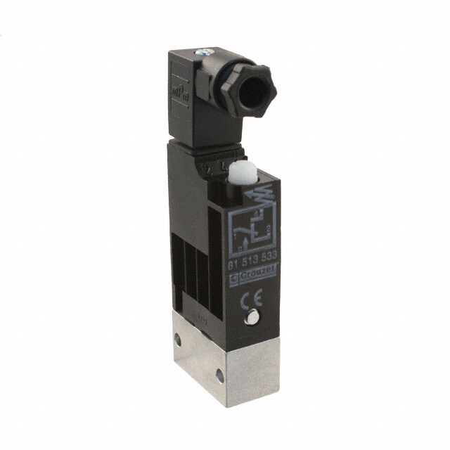
| WWW.CROUZET-CONTROL.COM | 36 | PNEUMATICS PRODUCTS Pressure switches - vacuum (electrical output) › Conform to the Low Voltage Directive › Can be used without enclosure according to IEC 664-1 pollution group III Part numbers Pressure and vacuum switches 81 513 552 81 513 502 81 513 501 81 513 522 Mounting DIN rail DIN rail DIN rail DIN rail Actuators Pressure Pressure Low pressure Vacuum Manual override with without without without Symbol Characteristics Pneumatic Push-in connection for semi-rigid mm Ø 4 ext. Ø 4 ext. Ø 4 ext. Ø 4 ext. connection tubing (NFE 49100) Tapped BSP via connector - - - - Protection IEC 529 IP 20 IP 20 IP 20 IP 20 Permissible fluid: air, inert gases and liquids l l l l Adjustment of switching pressure (* adjusted to 0.3) bar 2 ➞ 8 2 ➞ 8 0.3 ➞ 1.2 * -0.3 ➞ -0.8 Hysteresis at 1 bar bar 0.5 0.5 - - at 2 bars bar 0.6 0.6 - - at 4 bars bar 0.8 0.8 - - at 6 bars bar 1 1 - - max. 200 mb - - l - max. 250 mb - - - l Pressure to break - - - - Mechanical life (operations) 106 106 106 106 Contact rating (V resistive) 5A - 220-230 V 5A - 220-230 V 5A - 220-230 V 5A - 220-230 V Wire cross-section mm2 0.75 0.75 0.75 0.75 Operating temperature °C -10 ➞ +70 -10 ➞ +70 -10 ➞ +70 -10 ➞ +70 Weight g 48 46 46 46 Standard electrical contact V4 83 170 4 I W2 V4 83 170 4 I W2 V4 83 170 4 I W2 V4 83 170 4 I W2 UL and cUL approval MH15213 (R) MH15213 (R) MH15213 (R) MH15213 (R) Operation Electrical life Pressure operated Vacuum operated (Crouzet microswitch "V4" ref 83 170 4-1-W2) Number of cycles Electrical output -- cnoomrmmaollny closed contact RInedsuiscttiivvee cciirrccuuiitt { c a _ LRc_ o=s 5q m= s0.8 - normally open contact Mechanical life Adjustment of switching pres- sure 1 to 8 bars Standard microswitch 5 A / 220 V Manual override Pneumatic indicator Marking tag Current in Amps Pneumatic signal For continuous vacuum appli- cations, please consult us. Other information On request : - Microswitch V4 ref. 83 170 0 i W2 high current - Microswitch V4 ref. 83 170 9 i W2 low current
| WWW.CROUZET-CONTROL.COM | 37 | PNEUMATICS PRODUCTS 81 513 516 81 513 510 81 513 527 81 513 533 81 513 523 81 509 080 81 509 085 Base mounted Base mounted Base mounted 2 screws M4 2 screws M4 Base mounted Base mounted page 4/14 page 4/14 page 4/14 page 4/14 page 4/14 Pressure Pressure Vacuum Pressure Vacuum Pressure Pressure without with without without without without with Ø 4 ext. Ø 4 ext. Ø 4 ext. - -- - - - - - 1/8 BSP 1/8 BSP Via sub-base Via sub-base IP 54 IP 54 IP 54 IP 54 IP 54 IP 54 IP 54 l l l l l l l 2 ➞ 8 2 ➞ 8 -0.3 ➞ -0.9 2 ➞ 8 -0.3 ➞ -0.8 1.4 ± 0.5 1.4 ± 0.5 0.5 0.5 - 0.5 - - - 0.6 0.6 - 0.6 - - - 0.8 0.8 - 0.8 - - - 1 1 - 1 - - - - - - - - - - - - l - l - - - - - - - 0.6 ± 0.2 0.6 ± 0.2 106 106 106 106 106 106 106 5A - 220-230 V 5A - 220-230 V 5A - 220-230 V 5A - 220-230 V 5A - 220-230 V 5A - 220-230 V 5A - 220-230 V 0.75 0.75 0.75 0.75 0.75 1.5 1.5 -10 ➞ +70 -10 ➞ +70 -10 ➞ +70 -10 ➞ +70 -10 ➞ +70 -10 ➞ +70 -10 ➞ +70 56 58 56 65 65 80 80 V4 83 170 4 I W2 V4 83 170 4 I W2 V4 83 170 4 I W2 V4 83 170 4 I W2 V4 83 170 4 I W2 83 133 004 83 133 004 MH15213 (R) MH15213 (R) MH15213 (R) MH15213 (R) MH15213 (R) Electrical connections Dimensions Pressure switch with connector 81 516 082 81 513 501 - 81 513 502 81 513 552 - 81 513 502 81 513 516 - 81 513 510 81 513 533 81 513 522 - 81 513 552 81 513 501 - 81 513 522 81 513 527 81 513 523 1 - Common 4 - NO contact 2 - NC contact 81 513 510 81 513 516 - 81 513 527 For M4 screws length 24 mm 81 513 533 81 513 523 - 81 513 533 Pilot Pilot signal signal 81 509 080 - 81 509 085
| WWW.CROUZET-CONTROL.COM | 38 | PNEUMATICS PRODUCTS Adjustable pressure switches (manostats) (pneumatic output) › 100 % pneumatic Also available in ATEX version for use in poten- tially explosive atmospheres in accordance with 94/9/EC Directive Part numbers (and adjustment ranges) Adjustment range 50 → 500 mb 81 505 140 81 502 140 0.1 → 2.5 b 81 505 150 81 502 150 2 → 8 b 81 505 160 81 502 160 Version Positive output Negative output Accuracy 50 → 500 mb 10 % 10 % 0.1 → 2.5 b 4 % 4 % 2 → 8 b 4 % 4 % Symbol Characteristics Orifice diameter mm 2.5 2.5 Flow at 4 bars Nl/min 170 170 Hysteresis 50 → 500 mb 60 mb 60 mb 0.1 → 2.5 b 100 mb 100 mb 2 → 8 b 320 mb 320 mb Connection - sub-base pages 54/55 l l Operating temperature °C -5 ➞ +50 -5 ➞ +50 Mechanical life operations 3 x 10⁶ 3 x 10⁶ Weight g 160 160 Connections Example of pressure threshold adjustment (mini-regulator - manostat) Principle of operation The manostats provide an on or off output signal when the input signal reaches a predetermined pressure threshold. Positive output Negative output Output signal Pilot Output signal Pilot Hysteresis Hysteresis Switching Switching on on Switching off Switching off Dimensions 81 502 140 - 81 502 150 - 81 502 160 81 505 140 - 81 505 150 - 81 505 160 Other information Pressure switches with electrical output on request. ATEX version products are available in the following catologues: Pneumatic products for explosive atmospheres or on our website www.crouzet-Control.com
| WWW.CROUZET-CONTROL.COM | 39 | PNEUMATICS PRODUCTS Adjustable vacuum switches (vacuostat) › 100 % pneumatic › For vacuum -0,1 ➞ -0,9 Bar Part numbers 81 505 110 81 502 110 81 508 110 Positive output Negative output Electrical output Symbol Characteristics Adjustment range b - 0.1 ➞ -0.9 - 0.1 ➞ -0.9 - 0.1 ➞ -0.9 Flow at 6 bars Nl/min 170 170 170 Hysteresis mb 80 80 80 Connection - sub-base pages 54/55 l l l Operating temperature °C -5 ➞ +50 -5 ➞ +50 -5 ➞ +50 Mechanical life operations 3 x 10⁶ 3 x 10⁶ 3 x 10⁶ Weight g 160 160 180 Connections Example of use: Vacuum handling (vacuum generator, vacuum pad, vacuostats). Principle of operation Vacuostats provide an on or off output signal when the input signal reaches a predetermined pressure threshold. Positive output Negative output Output signal Output signal Switching off Switching off Switching Switching on on Hysteresis Hysteresis Vacuum Vacuum Vacuum Vacuum Dimensions 81 508 110 81 502 110 - 81 505 110
| WWW.CROUZET-CONTROL.COM | 40 | PNEUMATICS PRODUCTS Vacuum handling components › Sur le principe du Venturi › Facilement raccordable Also available in ATEX version for use in poten- tially explosive atmospheres in accordance with 94/9/EC Directive Part numbers Vacuum generators 81 535 301 81 545 001 81 545 005 Sub-base mounting Plug-in Plug-in Characteristics Push-in connectors for Male/Female/Female (MFF) - Ø 4 mm - semi-rigid tubing Female/Female/ - - Ø 6 mm (NFE 49100) Female (FFF) Operating pressure bar 2 → 8 2 → 8 2 → 8 Vacuum pad material - - - Weight g 80 13 25 Detection of the pressure decrease can be achieved by the use of manostats (see pages 38/39) Vacuum (mb) Vacuum (mb) Vacuum (mb) Suction flow Suction flow Suction flow Vacuum Vacuum (mb) (mb) Vacuum Flow (mb) Flow Flow Supply pressure (bar) Supply pressure (bar) Supply pressure (bar) Dimensions 81 535 301 81 545 001 Sub-base mounting 81 531… and 81 532… 2 push-in connectors Ø 4 mm Plug-in ferrule for push-in connector Ø 4 mm 4 2 29 11 40 81 545 005 30,7 10,7 Ø 4,5 15,5 11 ±0,19 2 3 push-in connectors Ø 6 mm 40 14,5 ±0,1 ATEX version products are available in the following catologues: Pneumatic products for explosive atmospheres or on our website www.crouzet-Control.com Désignation : Pneumatique Référence : 81540001 / 81541001 000 637 P2 SODIPE DESSINE PAR ST Désignation : Pneumatique Référence : 81540005 / 81541005 000 638 P2 SODIPE DESSINE PAR ST
| WWW.CROUZET-CONTROL.COM | 41 | PNEUMATICS PRODUCTS PNEUMATIC LOGIC COMPONENTS
| WWW.CROUZET-CONTROL.COM | 42 | PNEUMATICS PRODUCTS General characteristics Operating fluid flow graphs - Compressed air or inert gas. Conditions of use Ø of passage (mm) - Operating pressure 2 at 8 bars (except for special conditions). - Fluid: Filtered air to 50 microns - non lubricated. - Operating temperature from - 5° C to + 50° C (under + 5° C the dew point must be below 10° C for the application). P. supply pressure : - For optimum performance, the elements should be inter-connected 4 bars by air supply tubing with an internal diameter ≥ at 2.5 mm. Mounting recommendations - The elements should be mounted and piped in a clean atmosphere in order to prevent any form of pollution entering the system. - Minimum torque for element fixing screws: 5 cm/kg. - maximum torque for element fixing screws: 10 cm/kg. Characteristics common to all elements in the modular system - The characteristics have been obtained with a supply pressure at 6 bars. P. supply pressure: - The flow in NI/min is the number of litres of air at normal atmosphe- 6 bars ric pressure obtained with the output open to atmophere and the supply pressure at 4 bars - The consumption in NI/min is the number of litres of free air neces- sary for the unit to function. - kV = the flow coefficient of the equipment. Flow - Mechanical life > 107 operations. (NL/mn) Module with auto reset Sequencer modules Operation results from the combination of a sequential cycle. A system comprises individual modules which are joined together by means of a sub-base. Each module has a memory which delivers an output signal and receives an input signal. An indicator on each module allows the operator to monitor the pro- gress of the cycle and identity quickly and easily any fault which may occur. Brake This returns the memory spool to the reset condition only when the supply is lost Shift register The general principle is to advance the sequencer step by command impulses to the inputs of the even steps, alternating with the command impulses to the inputs of the odd steps. Used for example on a transfer machine to shift the information "bad component" collected at a test-test "n" steps further along the machine Operation results from the combination of three functions (memory, to a reject station. AND and OR) which constitute each module. Function diagram The memory activates the output and gives priority to the reset signal. The AND element ensures the transition to the next module but only if an input signal is present. The OR element ensures the resetting of all previously operated modules Function diagram Auto reset sequencer module sequencer module with maintained reset Brake This maintains the memory spool in position only when the supply is lost.
| WWW.CROUZET-CONTROL.COM | 43 | PNEUMATICS PRODUCTS Sequencer modules › 100 % pneumatic › Ideal for a simple pneumatic sequence Also available in ATEX version for use in poten- tially explosive atmospheres in accordance with 94/9/EC Directive 81 550 001 81 550 201 81 550 401 81 550 601 sequencer with 'maintain' Reset to zero - - Versions shift register - - with 'maintain' Reset to zero Symbol Characteristics Operating pressure bar 2 ➞ 8 2 ➞ 8 2 ➞ 8 2 ➞ 8 Orifice diameter mm 2.7 2.7 2.7 2.7 Flow at 6 bars Nl/min 150 150 150 150 Operating temperature °C -5 ➞ +50 -5 ➞ +50 -5 ➞ +50 -5 ➞ +50 Mechanical life 5 x 10⁶ at 6 bars l l l l Connection - Sub-base page 26 l l l l Weight g 70 70 70 70 Minimum pressure to be applied to port 1 - 4 - 7 to switch the valve supply pressure (bar) Principle of operation (supplied without logic element. For choice of units see pages 46/47) Sequencer module with maintained reset Shif register with maintained reset 1 - Input signal 1 - Input signal 2 - Supply 2 - Supply 3 - Output signal 3 - Output signal 4 - Start signal 4 - Start signal 5 - In cycle signal 5 - In cycle signal 6 - End of cycle signal 6 - End of cycle signal 7 - Reset to zero signal 7 - Reset to zero signal Dimensions Mounting plan for sequencer 2 holes M4 - minimum depth 7 mm ATEX version products are available in the following catologues: Pneumatic products for explosive atmospheres or on our website www.crouzet-crouzet.com
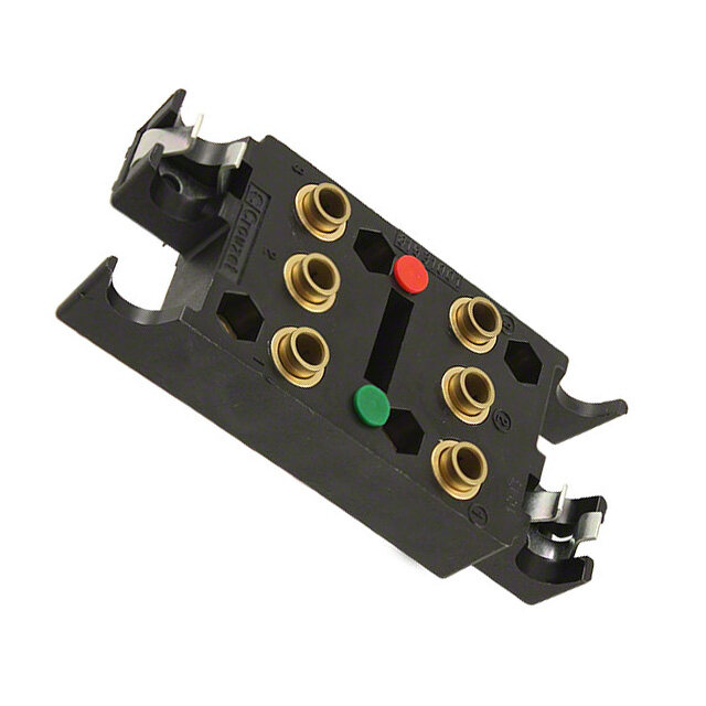
| WWW.CROUZET-CONTROL.COM | 44 | PNEUMATICS PRODUCTS Sequencer sub-bases Also available in ATEX version for use in poten- tially explosive atmospheres in accordance with 94/9/EC Directive 81 551 101 81 552 101 81 552 601 Front connecting (DIN-omega) Sub-base (DIN oméga) End bases - one pair Diversion base Versions Rear connecting (with clips) - - - Characteristics Sub-bases Rotatable connectors l l l (fitted) Pressure indicators l l l Operating temperature °C -5 ➞ +50 -5 ➞ +50 -5 ➞ +50 Weight g 55 135 60 Sequencer connections Front connecting 1 - Input port (green port 1) Ø 4 2 - Output port (red port 1) Ø 4 3 - Input port, cycle start (green port 1) Ø 4 4 - Output port, in-cycle signal (red port 1) Ø 4 5 - Output port, cycle end (red port 6) Ø 4 6 - Output port, cycle end (red port 6) Ø 4 7 - Input port, reset to zero (green port 7) Ø 4 8 - Output indicator (red) 9 - Input indicator (green) 10 - Cycle start indicator at port 4 (green) 11 - In-cycle indicator at port 5 (red) 12 - Input indicator at port 7 (green) 13 - End of cycle indicator at port 6 (red) 14 - Supply indicator at port 2 (yellow) 15 - Interconnecting ports 16 - Fixing screws 17 - Engraved arrow to indicate direction of sequence 18 - Marking tag 19 - Marking tag position 20 - Marking tag position 21 - Mounting tongue 22 - Mounting groove 23 - Sub-base 24 - End bases Dimensions Front connecting Mounted on Ω rail Sub-base End bases - one pair Push-in connection for semi-rigid tube Ø 4 mm (NFE 49100)
| WWW.CROUZET-CONTROL.COM | 45 | PNEUMATICS PRODUCTS 81 551 001 81 552 001 - - Sub-base (with clips) End bases - one pair - - - l -5 ➞ +50 -5 ➞ +50 40 120 Rear connecting 1 - Input port (marked port 1) 2 - Supply port (Port 2) 3 - Output port (Port 3) 4 - Cycle start signal port (Port 4) 5 - In-cycle signal port (Port 5) 6 - End of cycle signal port (Port 6) 7 - Reset to zero signal port (Port 7) 8 - Indicator at supply port 9 - Marking area Rear connecting Push-in connection for semi-rigid tubing Ø 4 mm (NFE 49100) 35 35 x N 35 17,8 7 0 81 551 001 6 8 Sub-base Mounted on steel rod Ø 8 mm End bases - one pair ATEX version products are available in the following catologues: Pneumatic products for explosive atmospheres or on our website www.crouzet-crouzet.com Désignation : Pneumatique Référence : 81551001 000 647 P2 SODIPE DESSINE PAR ST
| WWW.CROUZET-CONTROL.COM | 46 | PNEUMATICS PRODUCTS Logic elements › Performs "combined" Pneumatic › Easy to use Also available in ATEX version for use in poten- tially explosive atmospheres in accordance with 94/9/EC Directive OR 81 521 501 81 540 001 81 540 005 Functions AND - - - 81 522 501 YES - - - - NO - - - - Version On Sub-base Plug-in Plug-in On Sub-base page 4/14-4/15 Ø 4 Ø 6 page 4/14-4/15 Symbol Characteristics Push-in connection for semi-rigid Male/Female/Female - Ø 4 mm - - tubing (NFE 49100) Female/Female/Female - - Ø 6 mm - Colour Blue Blue Blue Green Operating pressure bar 2 ➞ 8 2 ➞ 8 2 ➞ 8 2 ➞ 8 Orifice diameter mm 2.7 2.7 4 2.7 Flow at 6 bars Nl/min 170 170 200 170 Pressure indicator l - - l Switching time ms - - - - Operating temperature °C -5 ➞ +50 -5 ➞ +50 -5 ➞ +50 -5 ➞ +50 Mechanical life operations >107 >107 >107 >107 Weight g 25 12 25 25 Pilot/pressure curves P.p : Pilot pressure P.a : Supply pressure Principle of operation Cellule OR Cellule AND The output signal "S" is present when a signal at The output signal "S" is present only when signals "a" OR "b" is present: "a" AND "b" are present simultaneously: S = a OR b S = a + b S = a AND b S = a . b Dimensions 81 521 501 - 81 522 501 81 540 005 - 81 541 005 81 540 001 - 81 541 001 Other information See pages 54/55 for mounting plan for logic elements.
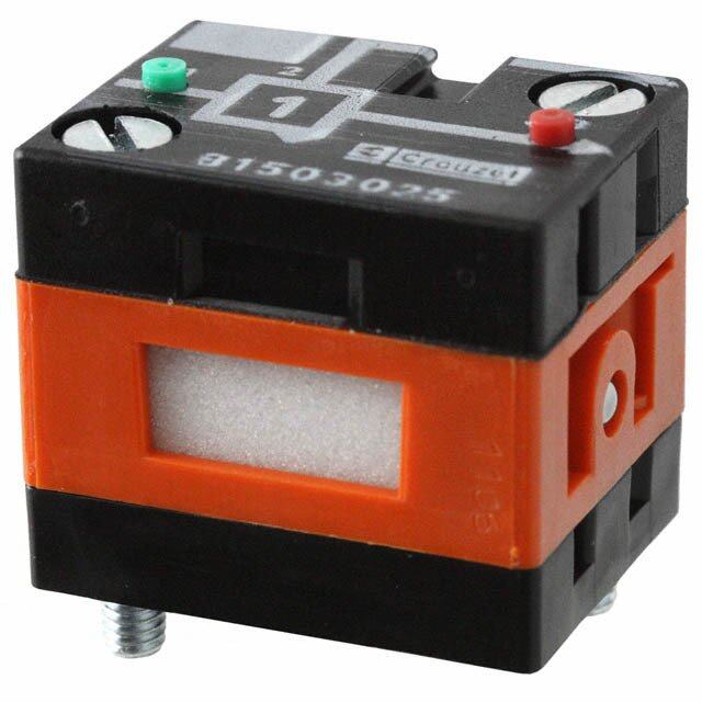
| WWW.CROUZET-CONTROL.COM | 47 | PNEUMATICS PRODUCTS - - - - - - 81 541 001 81 541 005 - - - - - - 81 501 025 81 503 025 - - - - - - 81 504 025 81 506 025 Plug-in Plug-in On sub-base Threshold Threshold Threshold Ø 4 Ø 6 page 36-37 On sub-base page On sub-base page On sub-base page 4/14-4/15 4/14-4/15 4/14-4/15 Ø 4 mm - - - - - - Ø 6 mm - - - - Green Green Yellow Orange Light grey Dark grey 2 ➞ 8 2 ➞ 8 2 ➞ 8 2 ➞ 8 2 ➞ 8 2 ➞ 8 2.7 4 2.7 2.7 2.7 2.7 150 200 170 170 170 170 - l l l l l - - < 4 < 4 < 4 < 4 -5 ➞ +50 -5 ➞ +50 -5 ➞ +50 -5 ➞ +50 -5 ➞ +50 -5 ➞ +50 >107 >107 >107 >107 >107 >107 13 25 30 30 30 30 P.p (bars) P.p (bars) P.p (bars) P.p (bars) P.a (bars) P.a (bars) P.a (bars) P.a (bars) YES element NOT element The output signal "S" is only present when the The output signal "s" is present only if the input signal pilot is present "a" is present: "a" is NOT present. The output signal is therefore the inverse of the pilot signal: S = a YES b S = a S= NOT a S = a If the supply port is connected to a 2nd input "b", the function obtained is called inhibition: S = NOT a AND b S = a . b 81 501 025 - 81 503 025 81 504 025 - 81 506 025 ATEX version products are available in the following catologues: Pneumatic products for explosive atmospheres or on our website www.crouzet-crouzet.com
| WWW.CROUZET-CONTROL.COM | 48 | PNEUMATICS PRODUCTS Memory element › 100 % pneumatic › Bistable pneumatic Also available in ATEX version for use in poten- tially explosive atmospheres in accordance with 94/9/EC Directive 81 523 201 81 523 601 Version With pressure With pressure indi- indicator cator and manual override Symbol Characteristics Colour Black Black Operating pressure bar 2 ➞ 8 2 ➞ 8 Orifice diameter mm 2.7 2.7 Minimum memory pilot pressure bar 2.5 2.5 Operating temperature °C -5 ➞ +50 -5 ➞ +50 Flow at 6 bars Nl/min 200 200 Connection - On sub-base page 4/14-4/15 l l Weight g 90 90 Principle of operation The function is that of a 4/2 valves. The appearence of signal "X1" causes the displacement of the slide valve. The output port "x" is then put under pressure. This state is remembered until the arrival of signal "X0". This signal reverses the slide valve, the output "x" is put under pressure. This state is likewise remembered. The output: - "x" under pressure indicates that the information in the MEMORY is "X1", - "x" under pressure indicates that the information in the MEMORY is "X0". Dimensions Dimensions of logic and memory elements 81 523 201 - 81 523 601 2 holes Ø 3.2 depth minimum 2.5 (location) Viewed from above ATEX version products are available in the following catologues: Pneumatic products for explosive atmospheres or on our website www.crouzet-control.com
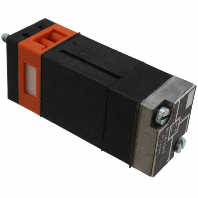
| WWW.CROUZET-CONTROL.COM | 49 | PNEUMATICS PRODUCTS Timers fixed timing › Fixed 0.4 s Also available in ATEX version for use in poten- tially explosive atmospheres in accordance with 94/9/EC Directive 81 503 540 Version Positive output Symbol Characteristics Timing s 0.4 Operating pressure bar 2 ➞ 8 Flow at 6 bars Nl/min 170 Orifice diameter mm 2.7 Accuracy % ± 5 Min. reset time s <0.1 Connection - On sub-base page 36-37 l Operating temperature °C -5 ➞ +50 Mechanical life operations >107 Weight g 106 Principle of operation with positive output Time Dimensions 81 503 540 ATEX version products are available in the following catologues: Pneumatic products for explosive atmospheres or on our website www.crouzet-crouzet.com
| WWW.CROUZET-CONTROL.COM | 50 | PNEUMATICS PRODUCTS Timers (with adjustable timing) › 60 s adjustable (60 s max.) Also available in ATEX version for use in potentially explosive atmospheres in accordance with 94/9/EC Directive 81 503 710 81 506 710 81 503 720 81 506 720 81 503 725 81 506 725 positive l - l - l - Function negative - l - l - l Symbol Characteristics Timing s 0.1 ➞ 15 0.1 ➞ 15 0.1 ➞ 30 0.1 ➞ 30 0.1 ➞ 60 0.1 ➞ 60 Operating pressure bar 2 ➞ 8 2 ➞ 8 2 ➞ 8 2 ➞ 8 2 ➞ 8 2 ➞ 8 Flow at 6 bars Nl/min 170 170 170 170 170 170 Orifice diameter mm 2.7 2.7 2.7 2.7 2.7 2.7 Accuracy % ± 5 ± 5 ± 5 ± 5 ± 5 ± 5 Min. reset time s <0.1 <0.1 <0.1 <0.1 <0.1 <0.1 Connection - On sub-base page 4/14-4/15 l l l l l l Operating temperature °C -5 ➞ +50 -5 ➞ +50 -5 ➞ +50 -5 ➞ +50 -5 ➞ +50 -5 ➞ +50 Mechanical life operations >107 >107 >107 >107 >107 >107 Weight g 90 90 100 100 120 120 Accessories Panel mounting adaptator 79 451 698 79 451 698 79 451 903 79 451 903 - - Weight g 53 53 53 53 - - Principle Principle of operation The operation of these pneumatic timers is similar to that of with positive output with negative output electronic timers (circuit with capacitor/resistor) Timing by charging of reservoir Time Time The reservoir fills via the flow restrictor until the switching point of the timer output is reached (positive or negative). The non-return valve allows the reservoir to be emptied rapidly for the next timing. Dimensions Adaptator 79 451 . . . L (mm) 81 503 710 - 81 506 710 78 For panel mounting, a pre-drilled 81 503 720 - 81 506 720 92 hole Ø 10.5 mm si required 81 503 725 - 81 506 725 125 ATEX version products are available in the following catologues: Pneumatic products for explosive atmospheres or on our website www.crouzet-control.com
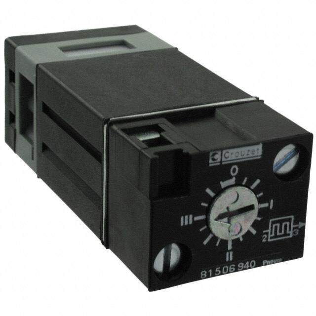
| WWW.CROUZET-CONTROL.COM | 51 | PNEUMATICS PRODUCTS Timers › Fixed and adjustable Also available in ATEX version for use in poten- tially explosive atmospheres in accordance with 94/9/EC Directive Single impulse generator Fixed 81 507 540 - - Adjustable - 81 507 720 - Adjustable frequency generator - - 81 506 940 Symbol Characteristics Timing s 0.4 0.1 ➞ 30 - Frequency Hz - - 0.02 ➞ 8 Operating pressure bar 2 ➞ 8 2 ➞ 8 2 ➞ 8 Flow at 6 bars Nl/min 170 170 170 Orifice diameter mm 2.7 2.7 2.7 Accuracy % ± 5 ± 5 ± 5 Min. reset time s <0.1 <0.1 <0.1 Connection - On sub-base page 4/14-4/15 l l l Operating temperature °C -5 ➞ +50 -5 ➞ +50 -5 ➞ +50 Mechanical life operations >107 >107 >107 Weight g 106 180 85 Accessories Panel mounting adaptators - 79 451 904 79 451 905 Weight (g) - 53 53 Principle of operation Single impulse generator Adjustable impulse generator Frequency generator Time Time Operating time Periode time Dimensions 79 451 Part numbers L (mm) 81 507 540 73 81 507 720 99 81 506 940 72 For panel mounting, a pre-drilled hole Ø 10.5 mm si required ATEX version products are available in the following catologues: Pneumatic products for explosive atmospheres or on our website www.crouzet-crouzet.com
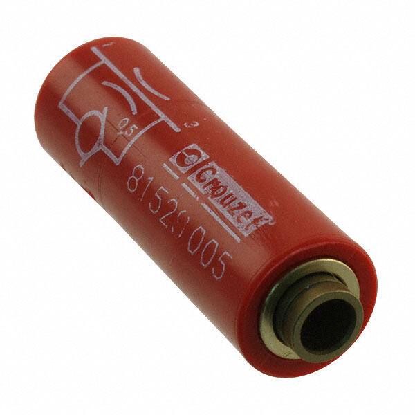
| WWW.CROUZET-CONTROL.COM | 52 | PNEUMATICS PRODUCTS Timing Accessories Also available in ATEX version for use in poten- tially explosive atmospheres in accordance with 94/9/EC Directive One-way in-line fixed Flow at 4 bars Ø orifice (mm) flow restritors Nm3/h 0.18 ➞ 0.30 0.3 white 81 529 003 - - - 0.35 ➞ 0.50 0.4 yellow 81 529 004 - - - 0.58 ➞ 0.77 0.5 red 81 529 005 - - - 0.80 ➞ 1.06 0.6 green 81 529 006 - - - 1.10 ➞ 1.39 0.7 blue 81 529 007 - - - 1.45 ➞ 1.65 0.8 grey 81 529 008 - - - 2.30 ➞ 2.80 1 black 81 529 010 - - - 0.08 ➞ 0.12 0.25 white 81 529 025 - - - One-way adjustable flow restritor - 81 525 101 81 526 001 - Capacity for timing 10 • 60 s - - - 79 458 808 Symbol Characteristics Free flow Nl/min Depending on orifice 30 200 - Orifice diameter mm Depending on orifice 0 ➞ 0.5 0 ➞ 1.7 - Operating pressure bars 1 ➞ 8 1 ➞ 8 2 ➞ 8 - Timing s - - - 10 ➞ 60 Capacity cm3 - - - 30 Sub-base page 4/14-4/15 - l l - Connection Push-in connection for semi- mm Ø 4 - - Ø 4 rigid tubing (NFE 49100) Operating temperature °C -5 ➞ +50 -5 ➞ +50 -5 ➞ +50 -5 ➞ +50 Weight g 8 60 70 40 Connections For timing circuit - One-way flow restrictor 81 525 1 - 81 529 0 (1) - Reservoir 79 458 018 (2) - Relay element 81 503 0 - 81 506 0 (3) page 4/6-4/7 (2) Sub-base page 4/14-4/15 (1) (3) Principle of operation One-way One-way with fixed flow with adjustable flow Dimensions 81 529 81 525 101 81 526 001 79 452 808 1 1 Ø 5 Ø 4 2 45 Ø 115 ATEX version products are available in the following catologues: Pneumatic products for explosive atmospheres or on our website www.crouzet-control.com Désignation : Pneumatique Référence : 79452808 Désignation : Pneumatique RéféreSncOe :DIPE DESSINE PAR ST 000 700 P2 81 529 0 000 701 P2 SODIPE DESSINE PAR ST
| WWW.CROUZET-CONTROL.COM | 53 | PNEUMATICS PRODUCTS Regulator accessories Also available in ATEX version for use in poten- tially explosive atmospheres in accordance with 94/9/EC Directive Part numbers Mini-détenteur 81 527 001 - Plug element - - In-line non-return - 81 529 901 Symbol Characteristics Operating pressure bars 2 → 8 2 → 8 Flow at 6 bars Nl/min 200 200 Adjustable output pressure bar 0,1 → 8 - Sub-base l Connection Push-in connection for semi- mm Ø 4 rigid tubing (NFE 49100) Weight g 150 70 Dimensions 81 529 901 5 1, 1 Ø 38,5 ATEX version products are available in the following catologues: Pneumatic products for explosive atmospheres or on our website www.crouzet-crouzet.com Désignation : Pneumatique Référence : 81 529 901 000 721 P2 SODIPE DESSINE PAR ST
| WWW.CROUZET-CONTROL.COM | 54 | PNEUMATICS PRODUCTS Sub-bases for logic elements Also available in ATEX version for use in poten- tially explosive atmospheres in accordance with 94/9/EC Directive 81 532 104 81 532 102 Two-hand start module l 1 l 1 Manostats - vacuostats l 1 l 1 Leak sensor and amplifier relays l 1 l 1 Logic elements AND Timers l 1 l 1 Regulator accessories l 1 l 1 Memory element - - Operating temperature °C -5 ➞ +50 -5 ➞ +50 Electro-pneumatic miniature solenoid l 1 l 1 NB: The number indicates the number of components mounted on the sub-base➞ Characteristics Push-in connection for semi-rigid tubing rotatable rotatable Ø 4 mm (NFE 49100) Fixation DIN rail 35 mm DIN rail 35 mm Weight g 56 52 Connections elements and relays Front connecting A B A - Single sub-base or end base B - Associable sub-base 1 - Input port (green port 1) 2 - Output port (red port 3) Selector 3 - Input/supply port (yellow port 2) Ø 4 4 - Input port integral to sub-base 5 - Input indicator (green) 6 - Output indicator (red) 7 - 1/4 turn screws 8 - Marking tag 9 - Arrow indicating flow direction 10 - Mounting tongue 11 - Mounting groove 12 - Selector Dimensions 81 532 104 3 x 81532102 A = 27 x N Mounted on Ω 13 5 3, 3 7 0 5 9 Associable sub-bases 19 Sub-base supply with inlet connection Push-in connection for semi-rigid 81532104 tubing Ø 4 mm (NFE 49100) ATEX version products are available in the following catologues: Pneumatic products for explosive atmospheres or on our website www.crouzet-control.com Désignation : Pneumatique Référence : 81 532 104 / 81 532 102 SODIPE DESSINE PAR ST 000 476 P2
| WWW.CROUZET-CONTROL.COM | 55 | PNEUMATICS PRODUCTS 81 542 002 81 532 001 81 531 001 Two-hand start module - l 1 l 2 Manostats - vacuostats - l 1 l 2 Leak sensor and amplifier relays - l 1 l 2 Logic elements AND Timers - l 1 l 2 Regulator accessories - l 1 l 2 Memory element l 1 - l 1 Operating temperature °C -5 ➞ +50 -5 ➞ +50 -5 ➞ +50 Electro-pneumatic miniature solenoid - l 1 l 2 Caractéristiques Push-in connection for semi-rigid tubing rear rear rotatable Ø 4 mm (NFE 49100) Fixation DIN rail 35 mm Clips for rails 2 M4 screws Ø 8 mm Weight g 95 10 35 Memory element sub-base, front and rear connecting Rear connection 1 - Input port X1 (green port 1) The modular system elements are fixed with 2 - Input port X0 (green port 1) two screws on the sub-base. 3 - Output port X (red port 3) A locating device on each logic element pre- 4 - Output port X (red port 3) vents incorrect assembly. 5 - Supply port (brass port 2) The logic element is connected via the 7 - 1/4 turn screws sub-base. This sub-base has 3 instant 8 - Input indicator connections for connecting semi-rigid tubes with outer Ø 4. 9 - Output indicator 10 - Marking tag 11 - Arrow indicating the flow direction 1 - Input signal 2 - Signal port for passive logic elements, air supply for active logic elements. 3 - Output signal 81 542 002 (for memory 81523201/601) 81 531 001 81 532 001 Push-in connection for Push-in connector Ø 4 Push-in connection for semi-rigid tubing Ø semi-rigid tubing 15 4 mm (NFE 49100) Ø 4 mm (NFE 49100) 5 4, Ø 1,5 2 1 8 6 5 3 4 7 0 1, 6 8 1 19 1,5 1 = = 2 Ø 4,5 4 19 35 18 27 Mounted on steel rod Ø 8 mm DIN rail 35 mm ATEX version products are available in the following catologues: Pneumatic products for explosive atmospheres or on our website www.crouzet-crouzet.com Désignation : Pneumatique Référence : Désignation : Pneumatique Référence : 81532 001 SODIPE 81531001 001 976 P2 DESSINE PAR ST 000 665 P2 SODIPE DESSINE PAR ST
| WWW.CROUZET-CONTROL.COM | 56 | PNEUMATICS PRODUCTS Mounting accessories Also available in ATEX version for use in potentially explosive atmospheres in accordance with 94/9/EC Directive 81 533 501 81 533 001 79 450 609 - Mounting equipment Hole domino Clip domino Bar clips - Ø 8 Supply manifold 13 outputs - - - 81 536 801 Characteristics Weight (g) 8 4 80 80 For mounting on For adjustable Packet of 100 the end of a mounting on a pieces zinc-coated mild zinc-coated mild steel rod steel rod Ø 8 mm on an Ø 8 mm on an asymmetrical asymmetrical DIN rail DIN rail Operating temperature °C -5 ➞ +50 -5 ➞ +50 -5 ➞ +50 -5 ➞ +50 Dimensions 81 536 804 Mounted on steel rod Ø 8 mm Ø 4 Ø 4 13 outputs push-in fittings 4 mm Ø 80 80 Ø 8 Input port 8Ø m m8 Ø 67 67 push-in fitting 35 35 25 25 Push-in connection for semi-rigid tubing Ø 4 mm (NFE 49100) Other information Use Weidmuller plastic labels for marking components part number FW 4734-6. ATEX version products are available in the following catologues: Pneumatic products for explosive atmospheres or on our website www.crouzet-control.com DésignDaétsioignn :ation :PneumPanteiquumeatique RéféreRnécfeé r:ence : 81 5368 18 05136 801 0000 70401 7 P412 P 2 SOSDOIPDEIPE DESSDINEES PSAINRE S PTAR ST
| WWW.CROUZET-CONTROL.COM | 57 | PNEUMATICS PRODUCTS ELECTRO -PNEUMATIC CONTROL VALVES
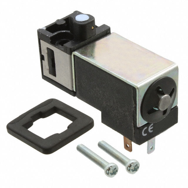
| WWW.CROUZET-CONTROL.COM | 58 | PNEUMATICS PRODUCTS Miniature solenoid valves for alternating current › Conform to the Low Voltage Directive › For mounting on sub-base or footprint in accordance with CNOMO recommendation E-06-36-120N Part numbers (and voltages) Consumption Voltage 2.5 VA 24 V a 50-60 Hz 81 519 080 81 519 380 81 519 680 2.5 VA 48 V a 50-60 Hz* - 81 519 381 81 519 681 2.5 VA 110 V a 50-60 Hz - 81 519 378 81 519 678 2.5 VA 220 V- 230 V a 50-60 Hz - 81 519 379 81 519 679 Function 3/2 NC 3/2 NC 3/2 NC Version Without With manual With manual manual override by override by lat- override impulse ching (1/4 turn) Characteristics Operating pressure bar 1➞ 8 1➞ 8 1 ➞ 8 Orifice diameter mm 0.5 0.5 0.5 Flow at 6 bars Nl/min 12 12 12 kV 0.12 0.12 0.12 Switching time ms 5 ➞ 15 5 ➞ 15 5 ➞ 15 Mechanical life (operations) 5 107 5 107 5 107 Operating temperature °C -10 ➞ +50 -10 ➞ +50 -10 ➞ +50 Compressed air or inert gas - oil-free l l l air filtered to 50 µ Duty factor 100 % ED 100 % ED 100 % ED Insulation class IEC 85 F F F Weight 35 35 35 Rotatable connector 4 positions in 90° steps l l l Degree of with sub-base (page 62) IEC 529 IP 20 IP 20 IP 20 protection with connector 81 516 082 (page 65) IEC 529 IP 65 IP 65 IP 65 UL and cUL approval MH 15085 MH 15085 MH 15085 15x15 mm footprint Dimensions 81 519 0 81 519 3 according to CNOMO E 06-36-120N 81 519 6 6 min. 9 min. Manual 26 9,4±0,1 override 2 x M3 - 6 H depth 6 7,5 min. Solenoid valve projecting on this side 3 2 1 x. 7 a 9, m 2 n. 4 mi 7 1,4 7,5 min. 1 3,8 3,8 2 or 3 Ø 1.6 min 2 max 16 15 Adjacent side of footprint when valves mounted in bank 1 - Supply 2 - Output 3 - Exhaust Désignation : Référence : Désignation : 81 519 034/035/334/335 Référence :81 519 01 003 231 P2 SODIPE DESSINE PAR DPH 003 585 P2 SODIPE DESSINE PAR JML
| WWW.CROUZET-CONTROL.COM | 59 | PNEUMATICS PRODUCTS Miniature solenoid valves for direct current › Conform to the Low Voltage Directive › For mounting on sub-base or footprint in accordance with CNOMO recommendation E-06-36-120N Also available in ATEX version for use in poten- tially explosive atmospheres in accordance with 94/9/EC Directive Part numbers (and voltages) Consumption Voltage 1 W 24 V c 81 519 032 81 519 332 81 519 632 81 519 340 Function 3/2 NC 3/2 NC 3/2 NC 3/2 NF Version Without With manual With maintained With maintained manual override by manual override manual override override impulse Characteristics Operating pressure bar 1➞ 8 1➞ 8 1➞ 8 1➞ 8 Orifice diameter mm 0.8 0.8 0.8 0,8 Flow at 6 bars Nl/min 25 25 25 25 kV 0.3 0.3 0.3 0,3 Switching time ms 5 ➞ 15 5 ➞ 15 5 ➞ 15 5 ➞ 15 Mechanical life (operations) 5 107 5 107 5 107 5 107 Operating temperature °C -10 ➞ +50 -10 ➞ +50 -10 ➞ +50 -10 ➞ +50 Compressed air or inert gas - oil-free l l l l air filtered to 50 µ Duty factor 100 % ED 100 % ED 100 % ED 100 % ED Insulation class IEC 85 F F F F Weight 35 35 35 35 Rotatable connector 4 positions in 90° steps l l l l Degree of with M12 5-pin connector IEC 529 – – – – protection with connector 81 516 082 IEC 529 IP 65 IP 65 IP 65 IP 65 UL and cUL approval MH 15085 MH 15085 MH 15085 MH 15085 15x15 mm footprint according to CNOMO E 06-36-120N 1 - Supply 6 min. 9 min. 2 - Output 2 x M3 - 6 H depth 6 3 - Exhaust 7,5 min. Solenoid valve projecting on this side 3 2 1 7 9, n. mi 7 1,4 7,5 min. 1 3,8 3,8 2 or 3 Ø 1.6 min 2 max Adjacent side of footprint when valves mounted in bank Encombrement 81 519 0 81 519 3 81 519 3 81 519 6 Manual Manual 26 9,4±0,1 26override 9,4±0,1 override 42 max. 42 max. 42 max. 16 15 21 15 21 ATEX version products are available in the following catologues: Pneumatic products for explosive atmospheres or on our website www.crouzet-control.com Désignation : Référence : 81 519 034/035/334/335 003 231 P2 SODIPE DESSINE PAR DPH Désignation : Désignation : Référence : 81R 5é1fé9r e3n -ce : 81 519 3 - Désignation : Référence :81 519 01 81 519 6 81 519 6 SODIPE SDEOSSDINEIP PAER JMDELSSINE0 P0AR3 J M5L86 P020 3 5 86 P2 003 585 P2 SODIPE DESSINE PAR JML
| WWW.CROUZET-CONTROL.COM | 60 | PNEUMATICS PRODUCTS
| WWW.CROUZET-CONTROL.COM | 61 | PNEUMATICS PRODUCTS Electro-pneumatic miniature control valves Mounting Miniature solenoid valves Indicators - LED seals - LED Valve modules 003229P51 - Poppet 3/2 monostable (17.5 mm) 4/2 monostable (17.5 mm) - Slide valve 4/2 bistable (35 mm) 003241 P51 4/2 monostable spring-return (35 mm) Sub-bases For For valve modules miniature solenoid valves Double Single 003234P5 Complete product 003233P5
| WWW.CROUZET-CONTROL.COM | 62 | PNEUMATICS PRODUCTS Valve modules › Monostable, bistable › 3/2, 4/2 Also available in ATEX version for use in poten- tially explosive atmospheres in accordance with 94/9/EC Directive 81 513 100 81 513 600 81 513 200 81 516 200 81 516 100 Function 3/2 NC monostable 3/2 NO monostable 4/2 monostable 4/2 bistable 4/2 monostable Symbol 14 3 1 2 Characteristics Width mm 17.5 17.5 17.5 35 35 Working pressure bars 3➞8 3➞8 3➞8 2➞8 3.5➞8 Orifice diameter mm 3 3 3 4 4 Flow at 6 bars with Ø 4 mm sub-base (page 63) 200 200 200 300 300 with Ø 6 mm sub-base (page 63) Nl/min 300 300 300 400 400 Flow Rate with Ø 4 mm sub-base (page 63) kV 2.2 2.2 2.2 4 4 with Ø 6 mm sub-base (page 63) 2.5 2.5 4 5 5 Operating temperature ° C -10 ➞ +50 -10 ➞ +50 -10 ➞ +50 -10 ➞ +50 -10 ➞ +50 Switching time for the valve only ms 15 15 15 50 50 Mechanical life operations 1.5 x 10⁷ 1.5 x 10⁷ 1.5 x 10⁷ 107 107 Weight g 38 38 38 106 106 Dimensions 81 513 81 516 ATEX version products are available in the following catologues: Pneumatic products for explosive atmospheres or on our website www.crouzet-control.com
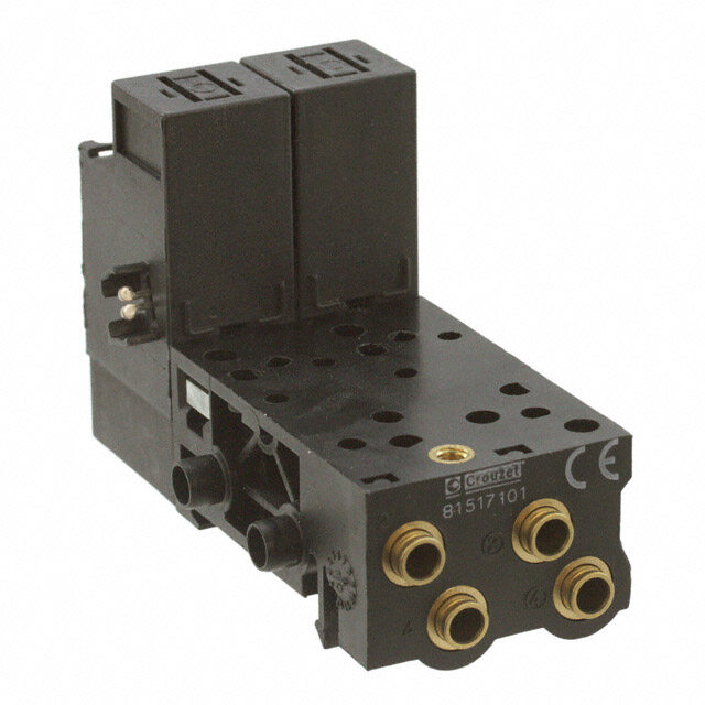
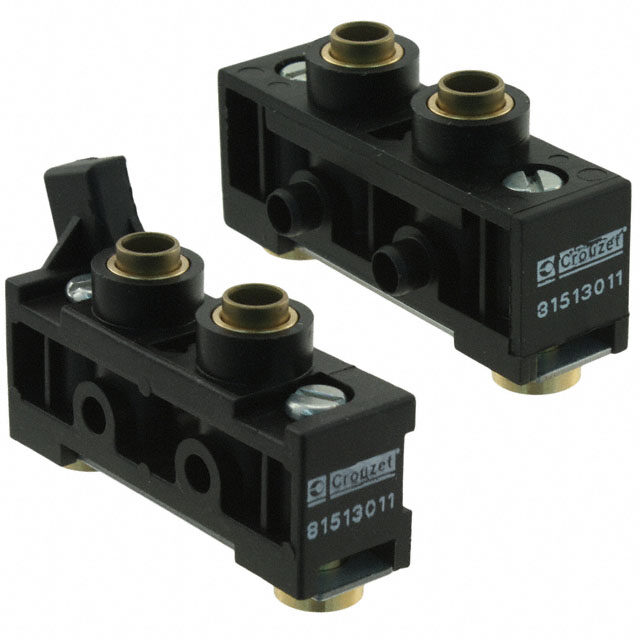
| WWW.CROUZET-CONTROL.COM | 63 | PNEUMATICS PRODUCTS Sub-bases and end bases for miniature control valves Also available in ATEX version for use in potentially explo- sive atmospheres in accordance with 94/9/EC Directive Part numbers Mounting Cabinet Cabinet Cabinet Cabinet Version 17.5 mm 35 mm - - Push-in connection for semi- Sub-bases Ø 4 mm 81 513 060 81 517 101 - - rigid tubing (NFE 49100) Ø 6 mm 81 513 065 81 517 201 - - End bases (pair) Ø 6 mm - - 81 513 011 - Intermediate supply Ø 6 mm - - - 81 513 001 module Characteristics Torque capacity mm2 3 3 - - UL and cUL approval MM15085 MM15085 - - DIN rail 35 mm DIN rail 35 mm DIN rail 35 mm DIN rail 35 mm Mounting Weight g 55 110 86 44 Connections Pneumatic 81 513 011 - 81 513 001 2 - Pneumatic output 2 Output at rest (NO) 4/2 (NO) 2 Output at rest * 4 - Pneumatic output 4 Output at rest * 3/2 or 4/2 (NC) 4 Output operating (NC) Note : E- saucbh- bsuabse-b 8a1se 5 c1a3n 0 a6c0c-0e6p5t : 1 relay 3/2 or 0 2 2 Supply ports 4/2, width 17.5 mm 0 3 2 Exhaust ports - sub-base 81 517 101-201 : 1 bistable relay 4/2 (width 35 mm) or 2 relays 3/2 or Integral push-in connections Ø 6 mm 4/2 (width 17.5 mm) Electrical Degree of protection : IP20 when assembled. A1 - Operating A1 - Pilot signal control signal A2 - Common (14) t Earth A2 - Common A1 - Rest control signal (12) A2 - Common t Earth Dimensions with miniature control valves (page 62) + miniature solenoid valves (page 58) + indicators (page 65) End bases Module Intermediate LED indicator base 0 8 1 3 1 3 1 3 2 4 6 1 3 5 17,5 17,5 35 17,5 17,5 5 77 max. 35 x (n module + 1) 2, 1 Ø 4 Ø 6 ATEX version products are available in the following catologues: Pneumatic products for explosive atmospheres or on our website www.crouzet-control.com Désignation : Pneumatique Référence : 81513 / 81516 002 872 P2 SODIPE DESSINE PAR ST
| WWW.CROUZET-CONTROL.COM | 64 | PNEUMATICS PRODUCTS Valves and solenoids valves assembled Contact us for Other versions Part numbers Function 3/2 NC 4/2 monostable Sub-base with push-in connection for semi-rigid Ø 4 ext. Ø 4 ext. tubing (NFE 49100) Version Solenoid valve Solenoid valve with manual override with manual override by impulse by impulse Voltage 24 VDC (+10% -15%) 81 513 103 81 513 203 Symbol Characteristics Operating pressure bar 3➞8 3➞8 Orifice diameter mm 3 3 Flow at sub-base 81 513 060 NL/min 200 200 6 bars sub-base 81 517 101 NL/min - - with sub-base 81 513 060 2.2 2.2 KV with sub-base 81 517 101 - - Operating temperature °C -10 ➞ +50 -10 ➞ +50 Switching time of the assembly ms 20 20 Mechanical life (operations) at 4 bars 1.5 x 10⁷ 1.5 x 10⁷ Valve position will be maintained in the event - - of pressure loss and/or electrical current loss Mounting DIN rail 35 mm DIN rail 35 mm Weight g 130 130 UL and cUL approval MH15085 MH15085 P rinciple of operation Dimensions Electrical signal 3/2 monostable module (NC) - Common A2 - Pilot signal A1 - Earth End bases - one pair Anti-return valve to prevent back pressures LED indicator Module Imnotedrumleediate LinEdDic a tor Plug-in solenoid valve Common exhaust Manual override Common air supply Poppet valve 80 1 3 1 3 1 3 Marking tag 2 4 6 1 3 5 Pneumatic indicator Pneumatic output 17,5 17,5 353 5x (n mo1d7u,5le + 1) 17,5 2,5 77 max. 1 4/2 monostable module 4/2 bistable module Ø 4 Ø 6 End bases not supplied (page 63) Intermediate bases not supplied (page 63) Indicators not supplied (page 65) Désignation : Pneumatique Référence : 81513 / 81516 SODIPE DESSINE PAR ST 002 872 P2
| WWW.CROUZET-CONTROL.COM | 65 | PNEUMATICS PRODUCTS Accessories Also available in ATEX ver- sion for use in potentially explosive atmospheres in accor- dance with 94/9/EC Directive Part numbers Visual 24 V - 50-60 Hz c 81 513 052 - - - - - indicators 48 V - 50-60 Hz c 81 513 055 - - - - - with anti- 110 V - 50-60 Hz c 81 513 058 - - - - - surge 230 V - 50-60 Hz 81 513 059 - - - - - (-10% +6 %) LED seal 12 to 24 V - DC - AC - 81 513 064 - - - - Packaging (by 5) (by 10) Exhaust Plug-in Ø 6 - - 81 537 001 - - - silencer Plug-in Ø 8 - - 81 537 201 - - - Connector for solenoid valve - - - 81 516 082 - - Without manual override - - - - 81 516 081 - Pneumatic With manual override pilots - - - - 81 516 091 - by impulse Push-in connection for semi-rigid tubing Ø 4 mm (NFE 49100) - - - - l - Blanking plate - - - - - 81 516 085 SSyymmbbooll 81 513 052 81 513 058 81 513 055 81 513 059 Characteristics Consumption W - 0.24 - - - - Temperature °C - - 10 ➞ +50 - - - - Connection mm - - - - Instantané Ø 4 ext. - Mounted between the pilot solenoid valve l l - - - - and the body of the module Supplied in multiples of 5 l - - - Supplied in multiples of 10 - l - l l l Packet of 10 pieces - - - - - l Weight g 6 2 30 10 5 3 1 Pilot Connection 2 signal t 80 Earth (4) 1 3 1 3 1 3 2 4 6 Dimensions 1 3 5 81 537 001 - 81 537 201 81 513 052 - 81 513 055 81 516 082 17,5 17,5 35 17,5 17,5 2,5 77 max. Mounted by plugging into push-in connector for semi- 81 513 058 - 81 513 059 Ø 4 Ø 6 1 rigid tubing (NFE 49100) 26 15,5+- 00,1 3 Ø 15 9 15 M + 0,15,5- 0 2 1 5 3 50 28 15 Pg 7 Ø 14 ATEX version products are available in the following catologues: Pneumatic products for explosive atmospheres or on our website www.crouzet-control.com Désignation : Référence : Désignation : Pneumatique Référence : 81 513 052/055/058/059 81513 / 81516 000 938 P3 SODIPE DESSINE PAR DPH SODIPE DESSINE PAR ST 002 872 P2 Désignation : Référence : Désignation : Pneumatique RéférenceD :ésignation : Pneumatique Référence : 002 870 P2 SODIPE DESSINE PAR DPH 81537001 / 81537201 815 160 82 SODIPE DESSINE PAR ST 00S0 O8D97IP PE2 D E S SINE PAR ST 001 351 P2
| WWW.CROUZET-CONTROL.COM | 66 | PNEUMATICS PRODUCTS Solenoid valves › Reduced "dimensions" › Mounted on sub-base Part numbers and voltages Function 3/2 NC Mounting On sub-base (54) Solenoid valves 24 V (+10% -15%) 81 519 732 with 24 V - 50/60 Hz (+10% -15%) 81 519 774 manual 48V - 50/60 Hz (+10% -15%) 81 519 775 override 110 V - 50/60 Hz (+10% -15%) 81 519 776 by impulse 220 - 230 V - 50/60 Hz (+10% -15%) 81 519 777 Symbol Characteristics Operating pressure bar 2 → 8 Orifice diameter mm 2.7 Flow at 6 bars Nl/min 170 Rotatable coil 4 positions in 90° steps l Degree of protection (with connector IP 65 81 516 082 not supplied) (see page 65) IEC 529 Mechanical life operations 1.5 x 10⁷ c W 1 C onsumption ~ VA 2.5 Operating temperature °C -5 ➞ +50 Weight g 70 UL and cUL approval MH15085 Principle of operation Connections Dimensions 81 519 { 1 - Supply 1-2 Pneumatic 2 - Output On separate sub-base { 1 - 2 - Pilot signal Electrical t Earth Electrical connection by connector 81 516 062 (see page 65)
| WWW.CROUZET-CONTROL.COM | 67 | PNEUMATICS PRODUCTS Miniature control valves, 17.5 mm ➜ Electro-pneumatic interface block Complete block, ready to install, consisting of: ■ Preconfigured 8-position sub-base ■ 6 4/2 monostable valve modules with 24 Vc pilot holes ■ 2 blanking plates (for extension if necessary) ■ 1 connection cable Part numbers 16 outputs 16 outputs Part numbers 81513241 81513238 Electrical characteristics Supply voltage 24 Vc ± -10% 24 Vc ± -10% Courant max. absorbé sur le 24 V de SUBD (mA) 500 500 Courant absorbé par chaque électrovanne 60 60 Response time (ms) 15 15 LED display Yes (integrated in the sub-base) Yes (integrated in the sub-base) Protection against voltage surges Yes Yes Electrical connections Type of cable Sub D9 AWG 24 wires Sub D9 AWG 24 wires Cable length 2 m 2 m Pneumatic characteristics Function 6 4/2 monostable valve Whitout modules (81513200) + 2 free positions Operating pressure bars 3 ➞8 b 3 ➞8 b Flow at 6 bars NL/mim 300 300 Mechanical life (operations) 1.5 x 10⁷ 1.5 x 10⁷ Working medium Compressed air or inert gas, 50 Compressed aire or inet gaés, µm filtered non-lubricated air 50 µm filtered non-lubricated air Pneumatic connections Power supply connection Push-in connection Ø 8 mm Push-in connection Ø 8 mm Output connections Push-in connection Ø 6 mm Push-in connection Ø 6 mm Connection of common exhaust Push-in connection Ø 8 mm Push-in connection Ø 8 mm General characteristics Operating temperature range IEC 68214 (oC) -5 ➞+50 -5 ➞+50 Storage temperature IEC 68-2-14 (°C) -15 ➞+50 -15 ➞+50 Protection (IEC/EN 60529) IP 20 IP20 Mounting On DIN rail or via two M5 On DIN rail or via two M5 screws screws (according to mounting (according to mounting plan) plan) Weight (g) 1350 960 Comments Other configurations on request Dimensions (mm) Connections 81513241 Connector wiring 1 2 3 4 5 1 2 3 4 5 A A24 224 224224 22242422 24422 EE 88,588,5 6 7 8 91 6 7 8 91 213213 93 93 EV1 ...... EV6 EV1 … EV6 1 1 EV EV 2 1 Commun 0 V 1Gemeinsam 0 V 2 2 Clips femelle Cl 2Clips für Schienen Cl 1
| WWW.CROUZET-CONTROL.COM | 68 | PNEUMATICS PRODUCTS Specific islands "for integrators" (supplied in packs of 20) Versions with interfaces 300 NL / mm Configuration 1 - Specify the number and type of interfaces (3 / 2 mono - 4 / 2 mono - 4 / 2 bistable) see page 62. 2 - Specify the voltage, the type and method of the control valve connections, see page: 58-59 (Example: 24 V DC with manual switch maintained, exit leads). 3 - Please send us your application specifying your requirements and quantities per year, and we will respond as soon as possible. Versions with interfaces 30 NL / mm Configuration 1 - Specify the voltage, the type and method of the control valve connections, see page: 58-59 (Example: 24 V DC with manual switch maintained, exit leads). 2 - Please send us your application specifying your requirements and quantities per year, and we will respond as soon as possible. Develop customised versions to specifications Crouzet analyses your needs and offers a customised solution.
| WWW.CROUZET-CONTROL.COM | 69 | PNEUMATICS PRODUCTS MULTI-FLUID SOLENOID VALVES
| WWW.CROUZET-CONTROL.COM | 70 | PNEUMATICS PRODUCTS Standard 2/2 miniature solenoid valves for fluids and inert gases › Autonomous › Mounted individually or in a bat- tery › Variable orientation coil › Low power consumption : 1 W › Quick to fit together, no tools nee- ded › M5 fittings or possibility of barb Mounting Individual Bank end valves (1 pair) Intermediate valve Part numbers Orifice Adjustment diameter KV range Power NC NC NC 0.8 mm 0.3 1 • 8 b 1W 81 546 001 81 547 001 81 547 501 Standard features Voltage 24V c Electrical connections 2.8 x 0.5 blade terminals (W7D5) at 9.4 mm centres Fluid connection tapped holes M5 Manual override + pressure indicator without General characteristics Response time 5 ➞ 15 ms Operating temperature - 5 °C ➞ +50 °C Viscosity range up to 30 cst Vibration resistance up to 5 g Air flow rate (at 2 bars) 15 ➞ 40 Nl/mn Maximum switching rate 30 Hz Individual mounting 32.5 g Weight Bank end/inner valves 35 g Body material Glass-reinforced polyamide 6.6 Mechanical life (operations) 1.5 x 10⁷ UL and cUL approval MH 15085 Accessories for 2/2 miniature solenoid valves Connector for solenoid val ve (see page 65) 81 516 082 Visual indicators 24 V-50/60 Hz CC 81 513 052 (see page 65) 48 V-50/60 Hz AC 81 513 055 110 V-50/60 Hz AC 81 513 058 220 V-50/60 Hz AC 81 513 059 LED seal 12-24 V a c 81 513 064 (see page 65) Dimensions Individual Bank end valves (1 pair) Intermediate valve 81 546 0 81 547 0 81 547 5 3 blade terminals 2.8 x 0.5 W7D5 3 blade terminals 2.8 x2 0.7.5 W7D5 3 blade terminals 2.8 x 0.5 W7D5 x a m 26.9 7.5/8 2 tapped h4o5le msax 9.75 8 30.2 max24.757.5/8 25 30.2 max24.757.5/8 11.25 11. 50.5 max 2 x 3.2 mm Ø ( M3 x 18 screw) 50.5 max 4.75±0.05 18 4.75±0.05 18 1 x 3.2 mm Ø ( M3 x 20 screw) = 20 == 15 == = = = 15= == = 15.5= = 1 9.4±0.1 M3 ±0. 9.4±0.1 M3 4.85 13 7 9.
| WWW.CROUZET-CONTROL.COM | 71 | PNEUMATICS PRODUCTS Standard 3/2 miniature solenoid valves for fluids and inert gases › Autonomous › Mounted individually or in a bat- tery › All connections on one face › Small size Mounting Individual Bank end valves (1 pair) Intermediate valve Part numbers Orifice Adjustment diameter KV Débit range Power NC NC NC 0.8 mm 0.3 25 1 • 8 b 1W 81 548 010 81 549 010 81 549 510 0.8 mm 0.3 1 • 8 b 2W 1.2 mm 0.6 40 - 0.9 • 3 b 2W 81 548 011 81 549 011 81 549 511 1.5 mm 0.8 60 0 • 2 b 2W 81 548 012 81 549 012 81 549 512 Standard features Voltage 24V c Electrical connections 2.8 x 0.5 blade terminals (W7D5) at 9.4 mm centres Fluid connection tapped holes M5 Manual override by impulse Pressure indicator without General characteristics Response time 5 ➞ 15 ms Operating temperature - 5 °C ➞ +50 °C Viscosity range up to 30 cst Vibration resistance up to 5 g Air flow rate (at 2 bars) 15 ➞ 40 Nl/min Maximum switching rate 30 Hz Individual mounting 32.5 g Weight Bank end/inner valves 35 g Body material Glass-reinforced polyamide 6.6 Mechanical life (operations) 1.5 x 10⁷ UL and cUL approval MH 15085 Accessories for 3/2 miniature solenoid valves Connector for solenoid val ve (see page 5/11) 81 516 082 Visual indicators 24 V-50/60 Hz DC 81 513 052 (see page 65) 48 V-50/60 Hz AC 81 513 055 110 V-50/60 Hz AC 81 513 058 220 V-50/60 Hz AC 81 513 059 LED seal 12-24 V a c 81 513 064 (see page 65) Dimensions Individual Bank end valves (1 pair) Intermediate valve 81 548 0 81 549 0 81 549 5 3 blade terminals 2.8 x 0.5 W7D5 3 blade terminals 2.8 x 0.5 W7D5 3 blade terminals 2.8 x 0.5 W7D5 Manual override Manual override Manual override 26.9 max21.57.5/82 tapped holes 86.25 30.2 max24.757.5/8 1.25 30.2 max24.757.5/8 1.25 1 1 10.25 50.5 max 50.5 max 51.2 max 4.75±0.05 18 2 x 3.2 mm Ø ( M3 x 18 screw) 4.75±0.05 18 1 x 3.2 mm Ø ( M3 x 20 screw) 10.59.5= 15 == = 24.85 15= == = 15.5= = 9.4±0.1 M3 6 3 9.4±0.1 M3 4.85 13
| WWW.CROUZET-CONTROL.COM | 72 | PNEUMATICS PRODUCTS TEACHING MATERIALS
| WWW.CROUZET-CONTROL.COM | 73 | PNEUMATICS PRODUCTS Teaching materials › Ideal for learning pneumatics › For high schools, colleges and training centres TEACHING Part numbers Training console PUMA 2000 81 598 940 - Add-on unit - 81 598 941 Weight (kg) 30 4 MATERIALS Characteristics Maintained sequencer sub-base assembly l - 1 relay sub-base l - 1 peripheral sub-base l - 1 plate with 8 push-buttons l - 1 plate with 8 indicators l - 1 basic console l - 1 cylinder mounting plate l - (3 cylinders + control valves + position detectors) 2 electro-pneumatic interface units - l 1 pneumo-electrical interface unit - l Dimensions 81 598 940
| WWW.CROUZET-CONTROL.COM | 74 | PNEUMATICS PRODUCTS List of part numbers Industrial part no. ATEX part no. Type Pages Industrial part no. ATEX part no. Type Pages 24 000 000 81 507 720 81 507 724 Frequency generator 51 24 678 127 Pushbutton 15 81 508 110 Vacuum switch 39 24 678 128 Pushbutton 15 81 509 080 Pressure switch 37 24 678 129 Pushbutton 15 81 509 085 Pressure switch 37 24 678 171 Mushroom button 15 81 510 001 Amplifier relay 34 24 678 172 Mushroom button 15 81 512 201 Special detector 31 24 678 173 Mushroom button 15 81 512 401 Special detector 31 24 678 174 Symmetrical toggle 15 81 513 001 81 513 039 Supply module 63 24 678 175 Lever toggle 15 81 513 011 81 513 040 End base 63 24 678 176 Symmetrical toggle 15 81 513 052 LED 65 24 678 177 Lever toggle 15 81 513 055 LED 65 24 678 178 Symmetrical toggle 15 81 513 058 LED 65 24 678 179 Lever toggle 15 81 513 059 LED 65 24 678 180 Key toggle 15 81 513 060 81 513 075 Sub-base 63 24 678 181 Key toggle 15 81 513 064 Indicator seal 65 24 678 182 Key toggle 15 81 513 065 81 513 076 Sub-base 63 24 679 702 Adaptor 14 81 513 100 81 513 196 Valve module 62 79 000 000 81 513 103 Valve module 64 79 451 698 79 451 698 Adaptor 50 81 513 200 81 513 234 Valve module 62 79 451 903 79 451 903 Adaptor 50 81 513 203 Valve module 64 79 451 904 79 451 904 Adaptor 51 81 513 501 Pressure switch 36 79 451 905 79 451 905 Adaptor 51 81 513 502 Pressure switch 36 79 452 103 Lever 28 81 513 509 Pressure switch 37 79 452 104 Lever 28 81 513 510 Pressure switch 37 79 452 123 Lever 28 81 513 516 Pressure switch 37 79 452 124 Lever 28 81 513 522 Vacuum switch 36 79 452 133 Lever 28 81 513 523 Vacuum switch 37 79 452 808 79 458 018 Capacity 52 81 513 527 Vacuum switch 37 81 000 000 81 513 533 Pressure switch 37 81 280 010 NO Microvalve 13-24 81 513 552 Pressure switch 36 81 280 510 NF Microvalve 13-24 81 513 600 81 513 612 Valve module 62 81 281 010 NO Microvalve 13-24 81 516 081 81 516 093 Pneumatic pilot 65 81 281 502 Limit switch 25 81 516 082 Connector 65 81 281 504 Limit switch 25 81 516 085 81 516 085 Blanking plate 65 81 281 508 Limit switch 25 81 516 091 Accessories 65 81 281 509 Limit switch 25 81 516 100 81 516 107 Valve module 62 81 281 510 NF Microvalve 13-24 81 516 200 81 516 208 Valve module 62 81 283 510 NF Microvalve 24 81 517 101 81 517106 Sub-base 63 81 290 001 81 290 006 Low-force detector 23 81 517 201 81 517 206 Sub-base 63 81 290 501 81 290 506 Low-force detector 23 81 519 032 81 519 035 Miniature solenoid valve 59 81 371 401 Special detector 32 81 519 080 Miniature solenoid valve 58 81 372 201 Special detector 32 81 519 332 81519 335 Miniature solenoid valve 59 81 372 401 Special detector 32 81 519 340 Miniature solenoid valve 59 81 372 901 Special detector 32 81 519 378 Miniature solenoid valve 58 81 501 025 81 501 031 YES element 47 81 519 379 Miniature solenoid valve 58 81 502 110 81 502 111 Vacuum switch 39 81 519 380 Miniature solenoid valve 58 81 502 140 81 502 141 Pressure switch 38 81 519 381 Miniature solenoid valve 58 81 502 150 81 502 151 Pressure switch 38 81 519 632 81 519 635 Miniature solenoid valve 59 81 502 160 81 502162 Pressure switch 38 81 519 678 Miniature solenoid valve 58 81 502 230 81 502 238 Amplifier 33 81 519 679 Miniature solenoid valve 58 81 502 320 81 502 322 Amplifier 33 81 519 680 Miniature solenoid valve 58 81 502 435 81 502 438 Relay for leak detector 31 81 519 732 Valve module 66 81 503 025 81 503 028 YES element 47 81 519 774 Valve module 66 81 503 540 81 503 543 Timer 49 81 519 775 Valve module 66 81 503 710 81 503 728 Timer 50 81 519 776 Valve module 66 81 503 720 81 503 729 Timer 50 81 519 777 Valve module 66 81 503 725 81 503 731 Timer 50 81 520 601 81 520 602 Plug-element 53 81 504 025 81 504 035 NO element 22-47 81 521 501 81 521 508 OR element 46 81 505 110 81 505 111 Vacuum switch 39 81 522 501 81 522 505 AND element 46 81 505 140 81 505 141 Pressure switch 38 81 523 201 81 523 205 Memory 48 81 505 150 81 505 151 Pressure switch 38 81 523 601 81 523 608 Memory 48 81 505 160 81 505 164 Pressure switch 38 81 525 101 81 525 106 Flow restrictor 52 81 505 230 81 505 231 Amplifier 33 81 526 001 81 526 006 Flow restrictor 52 81 505 320 81 505 321 Amplifier 33 81 527 001 Mini-regulator 53 81 505 435 81 505 437 Relay for leak detector 31 81 529 003 81 529 013 Flow restrictor 52 81 506 025 81 506 027 NO element 47 81 529 004 81 529 014 Flow restrictor 52 81 506 710 81 506 714 Timer 50 81 506 720 81 506 721 Timer 50 81 506 725 81 506 727 Timer 50 81 506 940 81 506 945 Frequency generator 51 81 507 540 81 507 543 Frequency generator 51
| WWW.CROUZET-CONTROL.COM | 75 | PNEUMATICS PRODUCTS List of part numbers Industrial part no. ATEX part no. Type Pages Industrial part no. ATEX part no. Type Pages 81 529 005 81 529 015 Flow restrictor 52 81 921 911 Miniature detector 27 81 529 006 81 529 016 Flow restrictor 52 81 921 912 Miniature detector 27 81 529 007 81 529 017 Flow restrictor 52 81 922 010 Compact detector 28 81 529 008 81 529 018 Flow restrictor 52 81 922 205 Compact detector 28 81 529 010 81 529 020 Flow restrictor 52 81 922 210 Compact detector 28 81 529 025 81 529 026 Flow restrictor 52 81 922 401 Compact detector 28 81 529 901 81 529 907 Non-return 53 81 923 001 Special detector 30 81 531 001 81 531 008 Sub-base 55 81 999 501 Control pedal 20 81 532 001 81 532 009 Sub-base 55 84 000 000 81 532 102 81 532 109 Sub-base 54 84 150 201 84 150 214 Indicator 20 81 532 104 81 532 111 Sub-base 54 84 150 202 84 150 215 Indicator 20 81 533 001 81 533 001 Clip domino 56 84 150 203 84 150 216 Indicator 20 81 533 501 81 533 501 Hole domino 56 84 150 204 84 150 217 Indicator 20 81 535 301 81 535 303 Vacuum generator 40 89 000 000 81 536 801 81 536 804 Supply base 56 89 538 201 Counter 19 81 540 001 81 540 015 OR element 46 89 543 101 3/2 NO valve 14 81 540 005 81 540 017 OR element 46 89 543 201 3/2 NO valve 14 81 541 001 81 541 015 AND element 47 89 543 501 3/2 NF valve 14 81 541 005 81 541 017 AND element 47 89 543 701 3/2 NF valve 14 81 542 002 81 542 004 Sub-base 55 89 543 005 3/2 NO valve + adaptor 14 81 545 001 81 545 012 Vacuum generator 40 89 543 105 3/2 NF valve + adaptor 14 81 545 005 81 545 013 Vacuum generator 40-70 89 543 205 3/2 NF valve+3/2 NO valve+adaptor 14 81 546 001 Miniature solenoid valve 40-70 89 543 305 3/2 NF valve+3/2 NF valve+adaptor 14 81 547 001 Miniature solenoid valve 70 99 000 000 81 547 501 Miniature solenoid valve 70 99 766 001 Counter 19 81 548 010 Miniature solenoid valve 71 99 766 002 Counter 19 81 548 011 Miniature solenoid valve 71 81 548 012 Miniature solenoid valve 71 81 549 010 Miniature solenoid valve 71 81 549 011 Miniature solenoid valve 71 81 549 012 Miniature solenoid valve 71 81 549 510 Miniature solenoid valve 71 81 549 511 Miniature solenoid valve 71 81 549 512 Miniature solenoid valve 70 81 550 001 81 550 013 Register module 43 81 550 201 81 550 213 Register module 43 81 550 401 81 550 403 Register module 43 81 550 601 81 550 603 Register module 43 81 551 001 81 551 004 Sub-base 45 81 551 101 81 551 104 Sub-base 44 81 552 001 81 552 005 Sub-base 45 81 552 101 81 552 105 Sub-base 44 81 552 601 81 552 605 Diversion base 44 81 580 101 Pneumatic relay 17 81 580 202 Pneumatic relay 17 81 580 503 Two-hand control module 18 81 580 504 Two-hand control module 18 81 598 940 Teaching materials 73 81 598 941 Teaching materials 73 81 715 511 Push buttons and actuators 12 81 715 512 Push buttons and actuators 12 81 716 511 Push buttons and actuators 12 81 716 512 Push buttons and actuators 12 81 733 511 Push buttons and actuators 12 81 735 011 Push buttons and actuators 12 81 735 511 Push buttons and actuators 12 81 735 512 Push buttons and actuators 12 81 737 501 Limit switch 25 81 921 501 Miniature detector 26 81 921 505 Miniature detector 30 81 921 701 Miniature detector 26 81 921 702 Miniature detector 26 81 921 707 Miniature detector 26 81 921 714 Miniature detector 27 81 921 717 Miniature detector 27 81 921 719 Miniature detector 27 81 921 806 Miniature detector 27 81 921 901 Miniature detector 27 81 921 902 Miniature detector 27
AMERICAS EUROPE / MIDDLE EAST / AFRICA ASIA / PACIFIC CANADA BELGIUM SPAIN / PORTUGAL CHINA InnoVista Sensors™ InnoVista Sensors™ InnoVista Sensors™ InnoVista Sensors™ 1461 Lawrence Drive Dieweg 3 B C/Lleó, 11-13 2º4ª 11th floor, Chang Feng Thousand Oaks, CA 91320 1180 Uccle - BELGIQUE 08911 Badalona - Barcelona International Tower, USA Tel.: +32 (0) 2 462 07 30 ESPAÑA 89 Yunling Road (East), Tel.: +1 (800) 677 5311 Fax: +32 (0) 2 461 00 23 Tel.: +34 (93) 484 39 70 Putuo District, Fax: +1 (800) 677 3865 klantenservice@crouzet.com Fax: +34 (93) 484 39 73 Shanghai 200 062 - CHINA customer.service@us.crouzet.com atencionalcliente@crouzet.com Tel.: +86 (21) 8025 7166 Fax: +86 (21) 6107 1771 china@crouzet.com MEXICO FRANCE SWITZERLAND INDIA InnoVista Sensors™ InnoVista Sensors™ InnoVista Sensors™ InnoVista Sensors™ Calzada Zavaleta 2505-C 2 rue du Docteur Henri Abel, Gewerbepark - Postfach 56 4th floor, Trident Towers, #23 100 Santa Cruz Buenavista CS 60059 5506 Mägenwil - SCHWEIZ Feet Ashoka Pillar Road, Puebla, 72150 - MEXICO 26902 Valence Cedex 9 Tel.: +49 (0) 2103/980-0 2nd Block, Jaynagar Tel.: +52 (222) 409 7000 FRANCE Fax: +49 (0) 2103/980-222 Bangalore 560 011 - INDIA mexico@crouzet.com Tel.: +33 (0) 475 802 101 kundenservice@crouzet.com Tel.: +91 (80) 4113 2204/05 Fax: +33 (0) 475 828 900 Fax: +91 (80) 4113 2206 relationclient@crouzet.com india@crouzet.com USA GERMANY / AUSTRIA THE NETHERLANDS SOUTH KOREA InnoVista Sensors™ InnoVista Sensors™ InnoVista Sensors™ InnoVista Sensors™ 1461 Lawrence Drive Otto-Hahn-Str. 3 Industrieweg 17 14F, Kbiz DMC Tower, Thousand Oaks, CA 91320 40721 Hilden 2382 NR Zoeterwoude 189, Seongam-Ro, Mapo-Gu, USA DEUTSCHLAND NEDERLAND Seoul 121-904 Tel.: +1 (800) 677 5311 Tel.: +49 (0) 2103/980-0 Tel.: +31 (0) 71-581 20 30 SOUTH KOREA Fax: +1 (800) 677 3865 Fax: +49 (0) 2103/980-222 Fax: +31 (0) 71-541 35 74 Tel.: +82 (2) 2629 8312 customer.service@us.crouzet.com kundenservice@crouzet.com klantenservice@crouzet.com Fax: +82 (2) 2630 9800 korea@crouzet.com COUNTRIES NOT LISTED ITALY COUNTRIES NOT LISTED EAST ASIA PACIFIC InnoVista Sensors™ InnoVista Sensors™ InnoVista Sensors™ InnoVista Sensors™ 1461 Lawrence Drive Via Viganò De Vizzi, 93/95 2 rue du Docteur Henri Abel, 10/F, Wharf T&T Centre, Harbour Thousand Oaks, CA 91320 20092 Cinisello Balsamo (Mi) CS 60059 City, 7 Canton Road, Tsim Sha Tsui, USA ITALIA 26902 Valence Cedex 9 Kowloon, HONG KONG Tel.: +1 (800) 677 5311 Tel.: +39 (02) 66 599 211 FRANCE Tel.: +86 (21) 8025 7177 Fax: +1 (800) 677 3865 Fax: +39 (02) 66 599 218 Tel.: +33 (0) 475 802 102 Fax: +86 (21) 6107 1771 customer.service@us.crouzet.com assistenzaclienti@crouzet.com Fax: +33 (0) 475 828 900 eap@crouzet.com www.crouzet.it customer.relation@crouzet.com d ar att L el ni a D os: ot h P 6 - 1 0 2 2/ 0 N | WWW.CROUZET-CONTROL.COM WWW.INNOVISTASENSORS.COM E A 11 0 0 6 7 6 ef.: R Warning: The product information contained in this catalogue is given purely as information and does not constitute a representation, warrantly or any form of contractual commitment. Crouzet Automatismes SAS and its subsidiaries reserve the right to modify their products without notice. It is imperative that we should be consulted over any particular use or application of our products and it is the responsability of the buyer to establish, particularly through all the appropriate tests, that the product is suitable for the use or application. Under no circumstances will our warranty apply, nor shall we be held responsible for any application (such as any modification, addition, deletion, use in conjunction with other electrical or electronic components, circuits or assemblies, or any other unsuitable material or substance) which has not been expressly agreed by us prior to the sale of our products. 2016_NEW-MASTER_CONTROL.indd 1 05/02/2016 09:24:36
Mouser Electronics Authorized Distributor Click to View Pricing, Inventory, Delivery & Lifecycle Information: C rouzet: 81580101 99766001 84150201 81715512 81546001 81548010 81549010 81549510 81735512 89543105 81735011 99766002 81580202 89543501 81281010 89543101 89543701 24678175 81281510 81735012 81735511 81580503 81733511 81716512 81715511 81716511 81580504 89543201 89543305 89543205 89538201 89543005