
 Datasheet下载
- 型号: 81529003
- 制造商: Crouzet
- 库位|库存: xxxx|xxxx
- 要求:
| 数量阶梯 | 香港交货 | 国内含税 |
| +xxxx | $xxxx | ¥xxxx |
查看当月历史价格
查看今年历史价格
81529003产品简介:
ICGOO电子元器件商城为您提供81529003由Crouzet设计生产,在icgoo商城现货销售,并且可以通过原厂、代理商等渠道进行代购。 81529003价格参考。Crouzet81529003封装/规格:气动,液压, One-Way Flow Restrictor, Fixed Free Hanging (In-Line)。您可以下载81529003参考资料、Datasheet数据手册功能说明书,资料中有81529003 详细功能的应用电路图电压和使用方法及教程。
Crouzet品牌的型号81529003属于气动和液压类产品,主要用于工业自动化控制系统中。该型号产品通常为电磁阀或相关控制元件,广泛应用于需要精确控制气体或液体流动的场合。

其典型应用场景包括:

1. 制造业设备:如注塑机、压铸机、装配线设备等,用于控制气动执行机构的动作。
2. 包装机械:在自动包装系统中,实现对气动夹具、推杆、传送带等部件的高效控制。
3. 食品与饮料行业:用于灌装机、封口机、清洗设备中的气动或液压系统控制,满足卫生和自动化需求。
4. 物流与搬运设备:如自动分拣系统、堆垛机、升降平台等,通过控制气动或液压驱动部件实现精准定位和动作控制。
5. 测试与检测设备:在压力测试、泄漏检测等系统中,作为关键控制元件使用。

该产品具有可靠性高、响应速度快、耐恶劣环境等特点,适合在工业现场复杂条件下稳定运行。具体功能需结合产品手册进一步确认。
| 参数 | 数值 |
| 产品目录 | 工业控制装置,量表 |
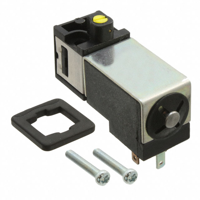
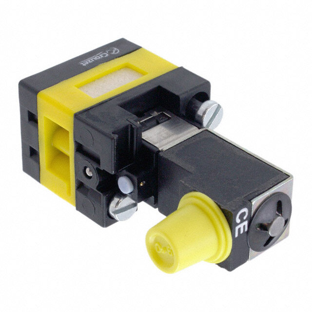
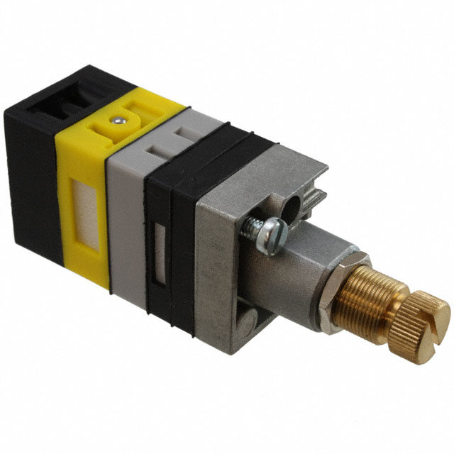
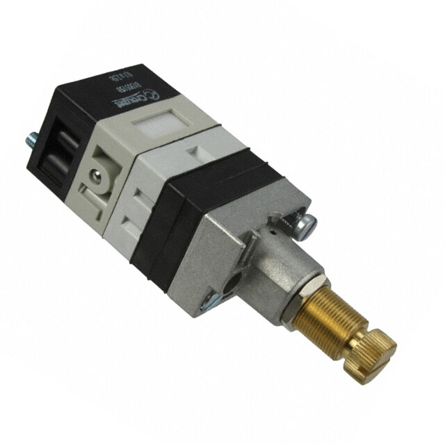
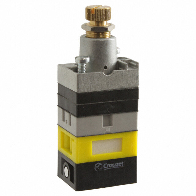
| 描述 | PNEUM FLOW RESTRICT UNIDIRECT |
| 产品分类 | 气动式 |
| 品牌 | Crouzet USA |
| 数据手册 | |
| 产品图片 |
|
| 产品型号 | 81529003 |
| rohs | 无铅 / 符合限制有害物质指令(RoHS)规范要求 |
| 产品系列 | * |
| 其它名称 | 81529003-ND |
| 其它有关文件 | |
| 标准包装 | 1 |


- 商务部:美国ITC正式对集成电路等产品启动337调查
- 曝三星4nm工艺存在良率问题 高通将骁龙8 Gen1或转产台积电
- 太阳诱电将投资9.5亿元在常州建新厂生产MLCC 预计2023年完工
- 英特尔发布欧洲新工厂建设计划 深化IDM 2.0 战略
- 台积电先进制程称霸业界 有大客户加持明年业绩稳了
- 达到5530亿美元!SIA预计今年全球半导体销售额将创下新高
- 英特尔拟将自动驾驶子公司Mobileye上市 估值或超500亿美元
- 三星加码芯片和SET,合并消费电子和移动部门,撤换高东真等 CEO
- 三星电子宣布重大人事变动 还合并消费电子和移动部门
- 海关总署:前11个月进口集成电路产品价值2.52万亿元 增长14.8%


PDF Datasheet 数据手册内容提取
| WWW.CROUZET-CONTROL.COM | 40 | PNEUMATICS PRODUCTS | WWW.CROUZET-CONTROL.COM | 41 | PNEUMATICS PRODUCTS Vacuum handling components › Sur le principe du Venturi › Facilement raccordable Also available in ATEX version for use in poten- tially explosive atmospheres in accordance with 94/9/EC Directive PNEUMATIC Part numbers Vacuum generators 81 535 301 81 545 001 81 545 005 Sub-base mounting Plug-in Plug-in LOGIC COMPONENTS Characteristics Push-in connectors for Male/Female/Female (MFF) - Ø 4 mm - semi-rigid tubing Female/Female/ - - Ø 6 mm (NFE 49100) Female (FFF) Operating pressure bar 2 → 8 2 → 8 2 → 8 Vacuum pad material - - - Weight g 80 13 25 Detection of the pressure decrease can be achieved by the use of manostats (see pages 38/39) Vacuum (mb) Vacuum (mb) Vacuum (mb) Suction flow Suction flow Suction flow Vacuum Vacuum (mb) (mb) Vacuum Flow (mb) Flow Flow Supply pressure (bar) Supply pressure (bar) Supply pressure (bar) Dimensions 81 535 301 81 545 001 Sub-base mounting 81 531… and 81 532… 2 push-in connectors Ø 4 mm Plug-in ferrule for push-in connector Ø 4 mm 4 2 29 11 40 81 545 005 30,7 10,7 Ø 4,5 15,5 11 ±0,19 2 3 push-in connectors Ø 6 mm 40 14,5 ±0,1 ATEX version products are available in the following catologues: Pneumatic products for explosive atmospheres or on our website www.crouzet.com Désignation : Pneumatique Référence : 81540001 / 81541001 000 637 P2 SODIPE DESSINE PAR ST Désignation : Pneumatique Référence : 81540005 / 81541005 000 638 P2 SODIPE DESSINE PAR ST
| WWW.CROUZET-CONTROL.COM | 42 | PNEUMATICS PRODUCTS | WWW.CROUZET-CONTROL.COM | 43 | PNEUMATICS PRODUCTS General characteristics Sequencer modules › 100 % pneumatic › Ideal for a simple pneumatic sequence Also available in ATEX version for use in poten- tially explosive atmospheres in accordance with 94/9/EC Directive Operating fluid flow graphs 81 550 001 81 550 201 81 550 401 81 550 601 - Compressed air or inert gas. sequencer with 'maintain' Reset to zero - - Versions Conditions of use shift register - - with 'maintain' Reset to zero Ø of passage (mm) - Operating pressure 2 at 8 bars (except for special conditions). - Fluid: Filtered air to 50 microns - non lubricated. Symbol - Operating temperature from - 5° C to + 50° C (under + 5° C the dew point must be below 10° C for the application). P. supply pressure : - For optimum performance, the elements should be inter-connected 4 bars by air supply tubing with an internal diameter ≥ at 2.5 mm. Characteristics Mounting recommendations Operating pressure bar 2 ➞ 8 2 ➞ 8 2 ➞ 8 2 ➞ 8 - The elements should be mounted and piped in a clean atmosphere Orifice diameter mm 2.7 2.7 2.7 2.7 in order to prevent any form of pollution entering the system. Flow at 6 bars Nl/min 150 150 150 150 - Minimum torque for element fixing screws: Operating temperature °C -5 ➞ +50 -5 ➞ +50 -5 ➞ +50 -5 ➞ +50 5 cm/kg. Mechanical life 5 x 10⁶ at 6 bars l l l l - maximum torque for element fixing screws: Connection - Sub-base page 26 l l l l 10 cm/kg. Weight g 70 70 70 70 Characteristics common to all elements in the modular system - The characteristics have been obtained with a supply pressure at 6 Minimum pressure to be applied to port 1 - 4 - 7 bars. P. supply pressure: to switch the valve - The flow in NI/min is the number of litres of air at normal atmosphe- 6 bars ric pressure obtained with the output open to atmophere and the supply pressure at 4 bars - The consumption in NI/min is the number of litres of free air neces- sary for the unit to function. - kV = the flow coefficient of the equipment. Flow - Mechanical life > 107 operations. (NL/mn) supply pressure (bar) Module with auto reset Sequencer modules Principle of operation Operation results from the combination of a sequential cycle. A (supplied without logic element. For choice of units see pages 46/47) system comprises individual modules which are joined together by means of a sub-base. Each module has a memory which delivers an Sequencer module with maintained reset Shif register with maintained reset output signal and receives an input signal. An indicator on each module allows the operator to monitor the pro- gress of the cycle and identity quickly and easily any fault which may occur. Brake This returns the memory spool to the reset condition only when the 1 - Input signal 1 - Input signal supply is lost 2 - Supply 2 - Supply Shift register 3 - Output signal 3 - Output signal 4 - Start signal 4 - Start signal The general principle is to advance the sequencer step by command 5 - In cycle signal 5 - In cycle signal impulses to the inputs of the even steps, alternating with the command 6 - End of cycle signal 6 - End of cycle signal impulses to the inputs of the odd steps. 7 - Reset to zero signal 7 - Reset to zero signal Used for example on a transfer machine to shift the information "bad component" collected at a test-test "n" steps further along the machine Dimensions Mounting plan for sequencer Operation results from the combination of three functions (memory, to a reject station. AND and OR) which constitute each module. Function diagram 2 holes M4 - minimum The memory activates the output and gives priority to the reset signal. depth 7 mm The AND element ensures the transition to the next module but only if an input signal is present. The OR element ensures the resetting of all previously operated modules Function diagram Auto reset sequencer module ATEX version products are available in the following catologues: Pneumatic products for explosive atmospheres or on our website www.crouzet.com sequencer module with maintained reset Brake This maintains the memory spool in position only when the supply is lost.
| WWW.CROUZET-CONTROL.COM | 44 | PNEUMATICS PRODUCTS | WWW.CROUZET-CONTROL.COM | 45 | PNEUMATICS PRODUCTS Sequencer sub-bases Also available in ATEX version for use in poten- tially explosive atmospheres in accordance with 94/9/EC Directive 81 551 101 81 552 101 81 552 601 81 551 001 81 552 001 Front connecting (DIN-omega) Sub-base (DIN oméga) End bases - one pair Diversion base - - Versions Rear connecting (with clips) - - - Sub-base (with clips) End bases - one pair Characteristics Sub-bases Rotatable connectors l l l - - (fitted) Pressure indicators l l l - l Operating temperature °C -5 ➞ +50 -5 ➞ +50 -5 ➞ +50 -5 ➞ +50 -5 ➞ +50 Weight g 55 135 60 40 120 Rear connecting Sequencer connections Front connecting 1 - Input port (green port 1) Ø 4 1 - Input port (marked port 1) 2 - Output port (red port 1) Ø 4 2 - Supply port (Port 2) 3 - Input port, cycle start (green port 1) Ø 4 3 - Output port (Port 3) 4 - Output port, in-cycle signal (red port 1) Ø 4 4 - Cycle start signal port (Port 4) 5 - Output port, cycle end (red port 6) Ø 4 5 - In-cycle signal port (Port 5) 6 - Output port, cycle end (red port 6) Ø 4 6 - End of cycle signal port (Port 6) 7 - Input port, reset to zero (green port 7) Ø 4 7 - Reset to zero signal port (Port 7) 8 - Output indicator (red) 8 - Indicator at supply port 9 - Input indicator (green) 9 - Marking area 10 - Cycle start indicator at port 4 (green) 11 - In-cycle indicator at port 5 (red) 12 - Input indicator at port 7 (green) 13 - End of cycle indicator at port 6 (red) 14 - Supply indicator at port 2 (yellow) 15 - Interconnecting ports 16 - Fixing screws 17 - Engraved arrow to indicate direction of sequence 18 - Marking tag 19 - Marking tag position 20 - Marking tag position 21 - Mounting tongue 22 - Mounting groove 23 - Sub-base 24 - End bases Dimensions Front connecting Rear connecting Push-in connection for semi-rigid Mounted on Ω rail tubing Ø 4 mm (NFE 49100) 35 35 x N 35 17,8 7 0 81 551 001 6 8 Sub-base Mounted on steel rod Ø 8 mm End bases - one pair Sub-base End bases - one pair Push-in connection for semi-rigid tube Ø 4 mm (NFE 49100) ATEX version products are available in the following catologues: Pneumatic products for explosive atmospheres or on our website www.crouzet.com Désignation : Pneumatique Référence : 81551001 000 647 P2 SODIPE DESSINE PAR ST
| WWW.CROUZET-CONTROL.COM | 46 | PNEUMATICS PRODUCTS | WWW.CROUZET-CONTROL.COM | 47 | PNEUMATICS PRODUCTS Logic elements › Performs "combined" Pneumatic › Easy to use Also available in ATEX version for use in poten- tially explosive atmospheres in accordance with 94/9/EC Directive OR 81 521 501 81 540 001 81 540 005 - - - - - - Functions AND - - - 81 522 501 81 541 001 81 541 005 - - - - YES - - - - - - 81 501 025 81 503 025 - - NO - - - - - - - - 81 504 025 81 506 025 Version On Sub-base Plug-in Plug-in On Sub-base Plug-in Plug-in On sub-base Threshold Threshold Threshold page 4/14-4/15 Ø 4 Ø 6 page 4/14-4/15 Ø 4 Ø 6 page 36-37 On sub-base page On sub-base page On sub-base page 4/14-4/15 4/14-4/15 4/14-4/15 Symbol Characteristics Push-in connection for semi-rigid Male/Female/Female - Ø 4 mm - - Ø 4 mm - - - - - tubing (NFE 49100) Female/Female/Female - - Ø 6 mm - - Ø 6 mm - - - - Colour Blue Blue Blue Green Green Green Yellow Orange Light grey Dark grey Operating pressure bar 2 ➞ 8 2 ➞ 8 2 ➞ 8 2 ➞ 8 2 ➞ 8 2 ➞ 8 2 ➞ 8 2 ➞ 8 2 ➞ 8 2 ➞ 8 Orifice diameter mm 2.7 2.7 4 2.7 2.7 4 2.7 2.7 2.7 2.7 Flow at 6 bars Nl/min 170 170 200 170 150 200 170 170 170 170 Pressure indicator l - - l - l l l l l Switching time ms - - - - - - < 4 < 4 < 4 < 4 Operating temperature °C -5 ➞ +50 -5 ➞ +50 -5 ➞ +50 -5 ➞ +50 -5 ➞ +50 -5 ➞ +50 -5 ➞ +50 -5 ➞ +50 -5 ➞ +50 -5 ➞ +50 Mechanical life operations >107 >107 >107 >107 >107 >107 >107 >107 >107 >107 Weight g 25 12 25 25 13 25 30 30 30 30 Pilot/pressure curves P.p (bars) P.p (bars) P.p (bars) P.p (bars) P.p : Pilot pressure P.a : Supply pressure P.a (bars) P.a (bars) P.a (bars) P.a (bars) Principle of operation Cellule OR Cellule AND YES element NOT element The output signal "S" is present when a signal at The output signal "S" is present only when signals The output signal "S" is only present when the The output signal "s" is present only if the input signal "a" OR "b" is present: "a" AND "b" are present simultaneously: pilot is present "a" is present: "a" is NOT present. The output signal is therefore the inverse of the pilot signal: S = a OR b S = a + b S = a AND b S = a . b S = a YES b S = a S= NOT a S = a If the supply port is connected to a 2nd input "b", the function obtained is called inhibition: S = NOT a AND b S = a . b Dimensions 81 521 501 - 81 522 501 81 540 005 - 81 541 005 81 540 001 - 81 541 001 81 501 025 - 81 503 025 81 504 025 - 81 506 025 Other information See pages 54/55 for mounting plan for logic elements. ATEX version products are available in the following catologues: Pneumatic products for explosive atmospheres or on our website www.crouzet.com
| WWW.CROUZET-CONTROL.COM | 48 | PNEUMATICS PRODUCTS | WWW.CROUZET-CONTROL.COM | 49 | PNEUMATICS PRODUCTS Memory element Timers fixed timing › 100 % pneumatic › Fixed 0.4 s › Bistable pneumatic Also available in ATEX version for use in poten- Also available in ATEX version for use in poten- tially explosive atmospheres in accordance with tially explosive atmospheres in accordance with 94/9/EC Directive 94/9/EC Directive 81 523 201 81 523 601 81 503 540 Version With pressure With pressure indi- Version Positive output indicator cator and manual override Symbol Symbol Characteristics Timing s 0.4 Operating pressure bar 2 ➞ 8 Characteristics Flow at 6 bars Nl/min 170 Colour Black Black Orifice diameter mm 2.7 Operating pressure bar 2 ➞ 8 2 ➞ 8 Accuracy % ± 5 Orifice diameter mm 2.7 2.7 Min. reset time s <0.1 Minimum memory pilot pressure bar 2.5 2.5 Connection - On sub-base page 36-37 l Operating temperature °C -5 ➞ +50 -5 ➞ +50 Operating temperature °C -5 ➞ +50 Flow at 6 bars Nl/min 200 200 Mechanical life operations >107 Connection - On sub-base page 4/14-4/15 l l Weight g 106 Weight g 90 90 Principle of operation with positive output Principle of operation The function is that of a 4/2 valves. The appearence of signal "X1" causes the displacement of the slide valve. The output port "x" is then put under pressure. This state is remembered until the arrival of signal "X0". This signal reverses the slide valve, the output "x" is put under pressure. This state is likewise remembered. The output: - "x" under pressure indicates that the information in the MEMORY is "X1", - "x" under pressure indicates that the information in the MEMORY is "X0". Time Dimensions Dimensions of logic and memory elements Dimensions 81 523 201 - 81 523 601 81 503 540 2 holes Ø 3.2 depth minimum 2.5 (location) Viewed from above ATEX version products are available in the following catologues: Pneumatic products for explosive atmospheres or on our website ATEX version products are available in the following catologues: Pneumatic products for explosive atmospheres or on our website www.crouzet.com www.crouzet.com
| WWW.CROUZET-CONTROL.COM | 50 | PNEUMATICS PRODUCTS | WWW.CROUZET-CONTROL.COM | 51 | PNEUMATICS PRODUCTS Timers (with adjustable timing) Timers › 60 s adjustable (60 s max.) › Fixed and adjustable Also available in ATEX version for use in potentially explosive Also available in ATEX version for use in poten- atmospheres in accordance tially explosive atmospheres in accordance with with 94/9/EC Directive 94/9/EC Directive 81 503 710 81 506 710 81 503 720 81 506 720 81 503 725 81 506 725 Single impulse generator Fixed 81 507 540 - - positive l - l - l - Adjustable - 81 507 720 - Function negative - l - l - l Adjustable frequency generator - - 81 506 940 Symbol Symbol Characteristics Characteristics Timing s 0.4 0.1 ➞ 30 - Timing s 0.1 ➞ 15 0.1 ➞ 15 0.1 ➞ 30 0.1 ➞ 30 0.1 ➞ 60 0.1 ➞ 60 Frequency Hz - - 0.02 ➞ 8 Operating pressure bar 2 ➞ 8 2 ➞ 8 2 ➞ 8 2 ➞ 8 2 ➞ 8 2 ➞ 8 Operating pressure bar 2 ➞ 8 2 ➞ 8 2 ➞ 8 Flow at 6 bars Nl/min 170 170 170 170 170 170 Flow at 6 bars Nl/min 170 170 170 Orifice diameter mm 2.7 2.7 2.7 2.7 2.7 2.7 Orifice diameter mm 2.7 2.7 2.7 Accuracy % ± 5 ± 5 ± 5 ± 5 ± 5 ± 5 Accuracy % ± 5 ± 5 ± 5 Min. reset time s <0.1 <0.1 <0.1 <0.1 <0.1 <0.1 Min. reset time s <0.1 <0.1 <0.1 Connection - On sub-base page 4/14-4/15 l l l l l l Connection - On sub-base page 4/14-4/15 l l l Operating temperature °C -5 ➞ +50 -5 ➞ +50 -5 ➞ +50 -5 ➞ +50 -5 ➞ +50 -5 ➞ +50 Operating temperature °C -5 ➞ +50 -5 ➞ +50 -5 ➞ +50 Mechanical life operations >107 >107 >107 >107 >107 >107 Mechanical life operations >107 >107 >107 Weight g 90 90 100 100 120 120 Weight g 106 180 85 Accessories Accessories Panel mounting adaptator 79 451 698 79 451 698 79 451 903 79 451 903 - - Panel mounting adaptators - 79 451 904 79 451 905 Weight g 53 53 53 53 - - Weight (g) - 53 53 Principle Principle of operation Principle of operation The operation of these pneumatic timers is similar to that of with positive output with negative output Single impulse generator Adjustable impulse generator Frequency generator electronic timers (circuit with capacitor/resistor) Timing by charging of reservoir Time Time Time Time Otimpeerating Periode time The reservoir fills via the flow restrictor until the switching point of the timer output is reached (positive or negative). The non-return valve allows the reservoir to be emptied rapidly for the next timing. Dimensions 79 451 Dimensions Adaptator 79 451 . . . Part numbers L (mm) 81 507 540 73 L (mm) 81 507 720 99 81 503 710 - 81 506 710 78 For panel mounting, a pre-drilled 81 506 940 72 For panel mounting, a pre-drilled 81 503 720 - 81 506 720 92 hole Ø 10.5 mm si required hole Ø 10.5 mm si required 81 503 725 - 81 506 725 125 ATEX version products are available in the following catologues: Pneumatic products for explosive atmospheres or on our website ATEX version products are available in the following catologues: Pneumatic products for explosive atmospheres or on our website www.crouzet.com www.crouzet.com
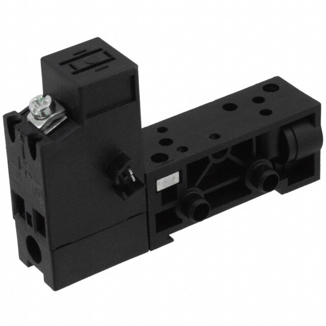
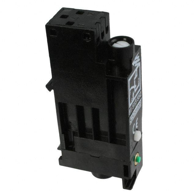
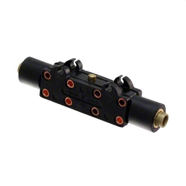
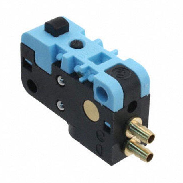
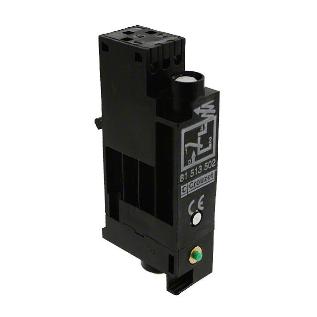
| WWW.CROUZET-CONTROL.COM | 52 | PNEUMATICS PRODUCTS | WWW.CROUZET-CONTROL.COM | 53 | PNEUMATICS PRODUCTS Timing Accessories Regulator accessories Also available in ATEX version for use in poten- Also available in ATEX version for use in poten- tially explosive atmospheres in accordance with tially explosive atmospheres in accordance with 94/9/EC Directive 94/9/EC Directive One-way in-line fixed Flow at 4 bars Ø orifice (mm) Part numbers flow restritors Nm3/h Mini-détenteur 81 527 001 - - 0.18 ➞ 0.30 0.3 white 81 529 003 - - - 0.35 ➞ 0.50 0.4 yellow 81 529 004 - - - 0.58 ➞ 0.77 0.5 red 81 529 005 - - - 0.80 ➞ 1.06 0.6 green 81 529 006 - - - Plug element - 81 520 601 - 1.10 ➞ 1.39 0.7 blue 81 529 007 - - - In-line non-return - - 81 529 901 1.45 ➞ 1.65 0.8 grey 81 529 008 - - - Symbol 2.30 ➞ 2.80 1 black 81 529 010 - - - 0.08 ➞ 0.12 0.25 white 81 529 025 - - - One-way adjustable flow restritor - 81 525 101 81 526 001 - Capacity for timing 10 • 60 s - - - 79 458 808 Symbol Characteristics Operating pressure bars 2 → 8 - 2 → 8 Flow at 6 bars Nl/min 200 - 200 Adjustable output pressure bar 0,1 → 8 - - Sub-base l l Characteristics C onnection Push-in connection for semi- mm Ø 4 Free flow Nl/min Depending on orifice 30 200 - rigid tubing (NFE 49100) Orifice diameter mm Depending on orifice 0 ➞ 0.5 0 ➞ 1.7 - Weight g 150 70 70 Operating pressure bars 1 ➞ 8 1 ➞ 8 2 ➞ 8 - Timing s - - - 10 ➞ 60 Dimensions Capacity cm3 - - - 30 81 529 901 81 520 601 Sub-base page 4/14-4/15 - l l - Connection Push-in connection for semi- mm Ø 4 - - Ø 4 rigid tubing (NFE 49100) Operating temperature °C -5 ➞ +50 -5 ➞ +50 -5 ➞ +50 -5 ➞ +50 1,5 Weight g 8 60 70 40 1 Ø Connections 38,5 For timing circuit - One-way flow restrictor 81 525 1 - 81 529 0 (1) - Reservoir 79 458 018 (2) - Relay element 81 503 0 - 81 506 0 (3) page 4/6-4/7 (2) Sub-base page 4/14-4/15 (1) (3) Principle of operation One-way One-way with fixed flow with adjustable flow Dimensions 81 529 81 525 101 81 526 001 79 452 808 1 1 Ø 5 Ø 4 2 45 Ø 115 ATEX version products are available in the following catologues: Pneumatic products for explosive atmospheres or on our website ATEX version products are available in the following catologues: Pneumatic products for explosive atmospheres or on our website www.crouzet.com www.crouzet.com Désignation : Pneumatique Référence : 81 529 901 000 721 P2 SODIPE DESSINE PAR ST Désignation : Pneumatique Référence : 79452808 Désignation : Pneumatique RéféreSncOe :DIPE DESSINE PAR ST 000 700 P2 81 529 0 000 701 P2 SODIPE DESSINE PAR ST
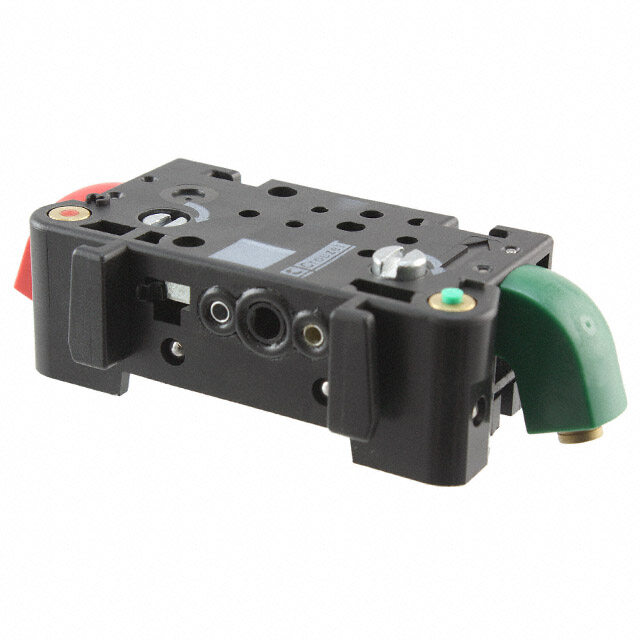
| WWW.CROUZET-CONTROL.COM | 54 | PNEUMATICS PRODUCTS | WWW.CROUZET-CONTROL.COM | 55 | PNEUMATICS PRODUCTS Sub-bases for logic elements Also available in ATEX version for use in poten- tially explosive atmospheres in accordance with 94/9/EC Directive 81 532 104 81 532 102 81 542 002 81 532 001 81 531 001 Two-hand start module l 1 l 1 Two-hand start module - l 1 l 2 Manostats - vacuostats l 1 l 1 Manostats - vacuostats - l 1 l 2 Leak sensor and amplifier relays l 1 l 1 Leak sensor and amplifier relays - l 1 l 2 Logic elements AND Timers l 1 l 1 Logic elements AND Timers - l 1 l 2 Regulator accessories l 1 l 1 Regulator accessories - l 1 l 2 Memory element - - Memory element l 1 - l 1 Operating temperature °C -5 ➞ +50 -5 ➞ +50 Operating temperature °C -5 ➞ +50 -5 ➞ +50 -5 ➞ +50 Electro-pneumatic miniature solenoid l 1 l 1 Electro-pneumatic miniature solenoid - l 1 l 2 NB: The number indicates the number of components mounted on the sub-base➞ Characteristics Caractéristiques PØu 4s hm-imn c(oNnFnEe c4t9io1n0 0fo)r semi-rigid tubing rotatable rotatable PØu 4s hm-imn c(oNnFnEe c4t9io1n0 0fo)r semi-rigid tubing rotatable rear rear Fixation DIN rail 35 mm DIN rail 35 mm Fixation DIN rail 35 mm 2 M4 screws Clips for rails Ø 8 mm Weight g 56 52 Weight g 95 10 35 Connections elements and relays Memory element sub-base, front and rear connecting Rear connection Front connecting 1 - Input port X1 (green port 1) The modular system elements are fixed with A B A - Single sub-base or end base 2 - Input port X0 (green port 1) two screws on the sub-base. B - Associable sub-base 3 - Output port X (red port 3) A locating device on each logic element pre- 1 - Input port (green port 1) 4 - Output port X (red port 3) vents incorrect assembly. 2 - Output port (red port 3) 5 - Supply port (brass port 2) The logic element is connected via the Selector 34 -- IInnppuutt/ spuoprtp ilnyt epgorrat l( ytoe lslouwb -pboarste 2) Ø 4 78 -- 1In/4p uttu rinnd siccaretowrs scwuoitbnh-n boeaucstteieor.n TØsh fi4os.r s cuobn-nbeacstein hga sse 3m iin-rsigtaidn tt ubes 5 - Input indicator (green) 9 - Output indicator 6 - Output indicator (red) 10 - Marking tag 7 - 1/4 turn screws 11 - Arrow indicating the flow direction 8 - Marking tag 9 - Arrow indicating flow direction 10 - Mounting tongue 11 - Mounting groove 1 - Input signal 12 - Selector 2 - Signal port for passive logic elements, air supply for active logic elements. 3 - Output signal Dimensions 81 542 002 (for memory 81523201/601) 81 531 001 81 532 001 81 532 104 3 x 81532102 Push-in connection for A = 27 x N Push-in connector Ø 4 Push-in connection for semi-rigid tubing Ø semi-rigid tubing 15 Mounted on Ω 4 mm (NFE 49100) Ø 4 mm (NFE 49100) 5 4, Ø 1,5 2 13 5 1 8 6 3, 5 3 4 3 7 0 1, 57 90 6 8 19 11,5 1 = = 2 Ø 4,5 4 19 35 18 27 Associable sub-bases 19 Mounted on steel rod Ø 8 mm Sub-base supply with inlet connection Push-in connection for semi-rigid DIN rail 35 mm 81532104 tubing Ø 4 mm (NFE 49100) ATEX version products are available in the following catologues: Pneumatic products for explosive atmospheres or on our website ATEX version products are available in the following catologues: Pneumatic products for explosive atmospheres or on our website www.crouzet.com www.crouzet.com Désignation : Pneumatique Référence : 81 532 104 / 81 532 102 Désignation : Pneumatique Référence : SODIPE DESSINE PAR ST 000 476 P2 Désignation : Pneumatique Référence : 81532 001 SODIPE DESS8I1N5E3 1P0A0R1 ST 001 976 P2 000 665 P2 SODIPE DESSINE PAR ST
| WWW.CROUZET-CONTROL.COM | 56 | PNEUMATICS PRODUCTS | WWW.CROUZET-CONTROL.COM | 57 | PNEUMATICS PRODUCTS Mounting accessories Also available in ATEX version for use in potentially explosive atmospheres in accordance with 94/9/EC Directive ELECTRO -PNEUMATIC 81 533 501 81 533 001 79 450 609 - Mounting equipment Hole domino Clip domino Bar clips - Ø 8 Supply manifold 13 outputs - - - 81 536 801 CONTROL VALVES Characteristics Weight (g) 8 4 80 80 For mounting on For adjustable Packet of 100 the end of a mounting on a pieces zinc-coated mild zinc-coated mild steel rod steel rod Ø 8 mm on an Ø 8 mm on an asymmetrical asymmetrical DIN rail DIN rail Operating temperature °C -5 ➞ +50 -5 ➞ +50 -5 ➞ +50 -5 ➞ +50 Dimensions 81 536 804 Mounted on steel rod Ø 8 mm Ø 4 Ø 4 13 outputs push-in fittings 4 mm Ø 80 80 Ø 8 Input port 8Ø m m8 Ø 67 67 push-in fitting 35 35 25 25 Push-in connection for semi-rigid tubing Ø 4 mm (NFE 49100) Other information Use Weidmuller plastic labels for marking components part number FW 4734-6. ATEX version products are available in the following catologues: Pneumatic products for explosive atmospheres or on our website www.crouzet.com DésignDaétsioignn :ation :PneumPanteiquumeatique RéféreRnécfeé r:ence : 81 5368 18 05136 801 0000 70401 7 P412 P 2 SOSDOIPDEIPE DESSDINEES PSAINRE S PTAR ST