ICGOO在线商城 > 74LVC162244APFG

 Datasheet下载
- 型号: 74LVC162244APFG
- 制造商: Integrated Device Technology
- 库位|库存: xxxx|xxxx
- 要求:
| 数量阶梯 | 香港交货 | 国内含税 |
| +xxxx | $xxxx | ¥xxxx |
查看当月历史价格
查看今年历史价格
74LVC162244APFG产品简介:
ICGOO电子元器件商城为您提供74LVC162244APFG由Integrated Device Technology设计生产,在icgoo商城现货销售,并且可以通过原厂、代理商等渠道进行代购。 提供74LVC162244APFG价格参考以及Integrated Device Technology74LVC162244APFG封装/规格参数等产品信息。 你可以下载74LVC162244APFG参考资料、Datasheet数据手册功能说明书, 资料中有74LVC162244APFG详细功能的应用电路图电压和使用方法及教程。
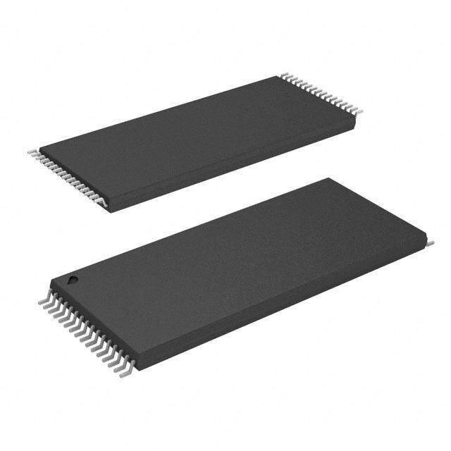
74LVC162244APFG 是瑞萨电子(Renesas Electronics America Inc.)推出的16位三态缓冲器/线驱动器,属于低压CMOS(LVC)系列,工作电压范围为1.65V–3.6V,具有低功耗、高速(tPD典型值约3.8ns)、高噪声容限及支持热插拔等特性。

其典型应用场景包括:
- 总线接口隔离与驱动:在FPGA、ASIC或微控制器与外部并行总线(如地址/数据总线)之间提供电平转换和负载驱动能力,增强信号完整性与扇出能力;
- 板级信号中继与电平适配:用于多板系统中跨电压域通信(如1.8V/2.5V/3.3V混合逻辑系统),实现不同电源域间的双向缓冲;
- 工业控制与通信模块:在PLC、HMI、工业网关中驱动LED阵列、继电器控制信号或RS-485/RS-232收发器使能端等中等电流负载;
- 测试设备与ATE系统:利用其16路独立三态控制(4组,每组4位,各带独立OE#)实现灵活的通道选通与信号路由;
- 存储扩展与I/O扩展应用:配合CPLD或专用桥接芯片,扩展处理器GPIO资源,驱动LCD并行接口、SRAM片选/控制信号等。

该器件采用TSSOP封装(PFG为10mm×5mm 48引脚),符合RoHS标准,适用于对空间、功耗与可靠性要求较高的嵌入式及工业电子系统。
| 参数 | 数值 |
| 品牌 | IDT |
| 产品目录 | 半导体 |
| 描述 | 缓冲器和线路驱动器 16-bit Buffer/Driver w/3-State Outputs |
| 产品分类 | 集成电路 - IC |
| 产品手册 | http://www.idt.com/document/dst/74lvc162244a-datasheet |
| 产品图片 |
|
| rohs | 符合RoHS |
| 产品系列 | 逻辑集成电路,缓冲器和线路驱动器,IDT 74LVC162244APFG |
| 产品型号 | 74LVC162244APFG |
| 产品种类 | 缓冲器和线路驱动器 |
| 传播延迟时间 | 4.4 ns |
| 低电平输出电流 | 12 mA |
| 商标 | IDT |
| 安装风格 | SMD/SMT |
| 封装 | Tube |
| 封装/箱体 | TVSOP-48 |
| 工厂包装数量 | 50 |
| 最大工作温度 | + 85 C |
| 最小工作温度 | - 40 C |
| 极性 | Non-Inverting |
| 每芯片的通道数量 | 4 |
| 电源电压-最大 | 3.6 V |
| 电源电压-最小 | 2.3 V |
| 电源电流 | 10 uA |
| 系列 | 74LVC162244A |
| 输入线路数量 | 16 Input |
| 输出类型 | 3-State |
| 输出线路数量 | 16 Output |
| 逻辑类型 | CMOS |
| 逻辑系列 | LVC |
| 零件号别名 | 74LVC162244A IDT74LVC162244APFG |
| 高电平输出电流 | - 12 mA |


- 商务部:美国ITC正式对集成电路等产品启动337调查
- 曝三星4nm工艺存在良率问题 高通将骁龙8 Gen1或转产台积电
- 太阳诱电将投资9.5亿元在常州建新厂生产MLCC 预计2023年完工
- 英特尔发布欧洲新工厂建设计划 深化IDM 2.0 战略
- 台积电先进制程称霸业界 有大客户加持明年业绩稳了
- 达到5530亿美元!SIA预计今年全球半导体销售额将创下新高
- 英特尔拟将自动驾驶子公司Mobileye上市 估值或超500亿美元
- 三星加码芯片和SET,合并消费电子和移动部门,撤换高东真等 CEO
- 三星电子宣布重大人事变动 还合并消费电子和移动部门
- 海关总署:前11个月进口集成电路产品价值2.52万亿元 增长14.8%
.jpg)


PDF Datasheet 数据手册内容提取
IDT74LVC162244A 3.3V CMOS 16-BIT BUFFER/DRIVER WITH 3-STATE OUTPUTS INDUSTRIAL TEMPERATURE RANGE 3.3V CMOS 16-BIT IDT74LVC162244A BUFFER/DRIVER WITH 3-STATE OUTPUTS AND 5 VOLT TOLERANT I/O FEATURES: DESCRIPTION: • Typical tSK(o) (Output Skew) < 250ps The LVC162244A 16-bit buffer/driver is built using advanced dual metal • ESD > 2000V per MIL-STD-883, Method 3015; > 200V using CMOS technology. The LVC162244A is designed specifically to improve machine model (C = 200pF, R = 0) both the performance and density of 3-state memory address drivers, clock • VCC = 3.3V ± 0.3V, Normal Range drivers, and bus-oriented receivers and transmitters. The device can be • VCC = 2.7V to 3.6V, Extended Range used as four 4-bit buffers, two 8-bit buffers, or one 16-bit buffer. This device • CMOS power levels (0.4μμμμμ W typ. static) provides true outputs and symmetrical active-low output-enable (OE) • All inputs, outputs, and I/O are 5V tolerant inputs. • Available in SSOP and TSSOP packages All pins of this 16-bit buffer/driver can be driven from either 3.3V or 5V devices. This feature allows the use of the device as a translator in a mixed 3.3V/5V supply system. DRIVE FEATURES: The LVC162244A has series resistors in the device output structure • Balanced Output Drivers: ±12mA which will significantly reduce line noise when used with light loads. This • Low switching noise driver has been developed to drive ±12mA at the designated threshold levels. APPLICATIONS: • 5V and 3.3V mixed voltage systems • Data communication and telecommunication systems FUNCTIONAL BLOCK DIAGRAM 1OE 1 3OE 25 1A1 47 2 1Y1 3A1 36 13 3Y1 1A2 46 3 1Y2 3A2 35 14 3Y2 1A3 44 5 1Y3 3A3 33 16 3Y3 1A4 43 6 1Y4 3A4 32 17 3Y4 2OE 48 4OE 24 2A1 41 8 2Y1 4A1 30 19 4Y1 2A2 40 9 2Y2 4A2 29 20 4Y2 2A3 38 11 2Y3 4A3 27 22 4Y3 2A4 37 12 2Y4 4A4 26 23 4Y4 IDT and the IDT logo is a registered trademark of Integrated Device Technology, Inc. INDUSTRIAL TEMPERATURE RANGE JULY 2015 1 © 2015 Integrated Device Technology, Inc. DSC-4729/5
IDT74LVC162244A 3.3V CMOS 16-BIT BUFFER/DRIVER WITH 3-STATE OUTPUTS INDUSTRIAL TEMPERATURE RANGE PIN CONFIGURATION ABSOLUTE MAXIMUM RATINGS(1) Symbol Description Max Unit VTERM(2) Terminal Voltage with Respect to GND –0.5 to +6.5 V VTERM(3) Terminal Voltage with Respect to GND –0.5 to +6.5 V 1OE 1 48 2OE TSTG Storage Temperature –65 to +150 °C 1Y1 2 47 1A1 IOUT DC Output Current –50 to +50 mA 1Y2 3 46 1A2 IIK Continuous Clamp Current, –50 mA IOK VI < 0 or VO < 0 GND 4 45 GND ICC Continuous Current through each ±100 mA ISS VCC or GND 1Y3 5 44 1A3 NOTES: 1Y4 6 43 1A4 1.Stresses greater than those listed under ABSOLUTE MAXIMUM RATINGS may cause permanent damage to the device. This is a stress rating only and functional operation VCC 7 42 VCC osef cthtieo ndse voicf et haist thsepseec ifoicr aatinoyn oitsh enro ct oinmdpitliioends. aEbxopvoes uthreo steo inadbicsaotluetde inm tahxei moupmer artaiotninagl 2Y1 8 41 2A1 conditions for extended periods may affect reliability. 2.VCC terminals. 2Y2 9 40 2A2 3.All terminals except VCC. GND 10 39 GND 2Y3 11 38 2A3 CAPACITANCE (TA = +25°C, F = 1.0MHz) 2Y4 12 37 2A4 Symbol Parameter(1) Conditions Typ. Max. Unit 3Y1 13 36 3A1 CIN Input Capacitance VIN = 0V 4.5 6 pF COUT Output Capacitance VOUT = 0V 6.5 8 pF 3Y2 14 35 3A2 CI/O I/O Port Capacitance VIN = 0V 6.5 8 pF GND 15 34 GND NOTE: 1.As applicable to the device type. 3Y3 16 33 3A3 3Y4 17 32 3A4 PIN DESCRIPTION VCC 18 31 VCC Pin Names Description 4Y1 19 30 4A1 xOE 3-State Output Enable Inputs (Active LOW) xAx Data Inputs 4Y2 20 29 4A2 xYx 3-State Outputs GND 21 28 GND 4Y3 22 27 4A3 23 4Y4 26 4A4 FUNCTION TABLE (EACH 4-BIT BUFFER)(1) 4OE 24 25 3OE Inputs Outputs xOE xAx xYx SSOP / TSSOP L H H TOP VIEW L L L H X Z NOTE: 1.H = HIGH Voltage Level X = Don’t Care L = LOW Voltage Level Z = High-Impedance 2
IDT74LVC162244A 3.3V CMOS 16-BIT BUFFER/DRIVER WITH 3-STATE OUTPUTS INDUSTRIAL TEMPERATURE RANGE DC ELECTRICAL CHARACTERISTICS OVER OPERATING RANGE Following Conditions Apply Unless Otherwise Specified: Operating Condition: TA = –40°C to +85°C Symbol Parameter Test Conditions Min. Typ.(1) Max. Unit VIH Input HIGH Voltage Level VCC = 2.3V to 2.7V 1.7 — — V VCC = 2.7V to 3.6V 2 — — VIL Input LOW Voltage Level VCC = 2.3V to 2.7V — — 0.7 V VCC = 2.7V to 3.6V — — 0.8 IIH Input Leakage Current VCC = 3.6V VI = 0 to 5.5V — — ±5 μA IIL IOZH High Impedance Output Current VCC = 3.6V VO = 0 to 5.5V — — ±10 μA IOZL (3-State Output pins) IOFF Input/Output Power Off Leakage VCC = 0V, VIN or VO ≤ 5.5V — — ±50 μA VIK Clamp Diode Voltage VCC = 2.3V, IIN = –18mA — –0.7 –1.2 V VH Input Hysteresis VCC = 3.3V — 100 — mV ICCL Quiescent Power Supply Current VCC = 3.6V VIN = GND or VCC — — 10 μA ICCH ICCZ 3.6 ≤ VIN ≤ 5.5V(2) — — 10 ΔICC Quiescent Power Supply Current One input at VCC - 0.6V, other inputs at VCC or GND — — 500 μA Variation NOTES: 1. Typical values are at VCC = 3.3V, +25°C ambient. 2. This applies in the disabled state only. OUTPUT DRIVE CHARACTERISTICS Symbol Parameter Test Conditions(1) Min. Max. Unit VOH Output HIGH Voltage VCC = 2.3V to 3.6V IOH = – 0.1mA VCC – 0.2 — V VCC = 2.3V IOH = – 4mA 1.9 — IOH = – 6mA 1.7 — VCC = 2.7V IOH = – 4mA 2.2 — IOH = – 8mA 2 — VCC = 3V IOH = – 6mA 2.4 — IOH = – 12mA 2 — VOL Output LOW Voltage VCC = 2.3V to 3.6V IOL = 0.1mA — 0.2 V VCC = 2.3V IOL = 4mA — 0.4 IOL = 6mA — 0.55 VCC = 2.7V IOL = 4mA — 0.4 IOL = 8mA — 0.6 VCC = 3V IOL = 6mA — 0.55 IOL = 12mA — 0.8 NOTE: 1. VIH and VIL must be within the min. or max. range shown in the DC ELECTRICAL CHARACTERISTICS OVER OPERATING RANGE table for the appropriate VCC range. TA = – 40°C to + 85°C. 3
IDT74LVC162244A 3.3V CMOS 16-BIT BUFFER/DRIVER WITH 3-STATE OUTPUTS INDUSTRIAL TEMPERATURE RANGE OPERATING CHARACTERISTICS, TA = 25°C Symbol Parameter Test Conditions Typical Unit CPD Power Dissipation Capacitance per Buffer/Driver Outputs enabled CL = 0pF, f = 10Mhz 35 pF CPD Power Dissipation Capacitance per Buffer/Driver Outputs disabled 4 SWITCHING CHARACTERISTICS(1) VCC = 2.7V VCC = 3.3V ± 0.3V Symbol Parameter Min. Max. Min. Max. Unit tPLH Propagation Delay — 5.6 1.1 4.4 ns tPHL xAx to xYx tPZH Output Enable Time — 6.9 1 5.5 ns tPZL xOE to xYx tPHZ Output Disable Time — 6.8 1.8 6.3 ns tPLZ xOE to xYx tSK(o) Output Skew(2) — — — 500 ps NOTES: 1. See TEST CIRCUITS AND WAVEFORMS. TA = – 40°C to + 85°C. 2. Skew between any two outputs of the same package and switching in the same direction. 4
IDT74LVC162244A 3.3V CMOS 16-BIT BUFFER/DRIVER WITH 3-STATE OUTPUTS INDUSTRIAL TEMPERATURE RANGE TEST CIRCUITS AND WAVEFORMS TEST CONDITIONS VIH Symbol VCC(1)= 3.3V±0.3V VCC(1)= 2.7V VCC(2)= 2.5V±0.2V Unit SAME PHASE VT INPUT TRANSITION 0V VLOAD 6 6 2 x Vcc V tPLH tPHL OUTPUT VOH VIH 2.7 2.7 Vcc V VT VT 1.5 1.5 Vcc / 2 V VOL tPLH tPHL VLZ 300 300 150 mV OPPOSITE PHASE VIH VT VHZ 300 300 150 mV INPUT TRANSITION 0V CL 50 50 30 pF LVC Link VLOAD Propagation Delay VCC Open ENABLE DISABLE VIH 500 GND CONTROL VT Pulse(1, 2) VIN D.U.T. VOUT INPUT tPZL tPLZ 0V Generator OUTPUT VLOAD/2 VLOAD/2 SWITCH RT CL 500 NORMALLOLWY CLOStEPZDH VT tPHZ VVOOLL+VLZ OUTPUT SWITCH VOH LVC Link NORMALLY OPEN VT VOH-VHZ Test Circuit for All Outputs HIGH 0V 0V DEFINITIONS: LVC Link CL = Load capacitance: includes jig and probe capacitance. Enable and Disable Times RT = Termination resistance: should be equal to ZOUT of the Pulse Generator. NOTE: NOTES: 1. Diagram shown for input Control Enable-LOW and input Control Disable-HIGH. 1.Pulse Generator for All Pulses: Rate ≤ 10MHz; tF ≤ 2.5ns; tR ≤ 2.5ns. 2.Pulse Generator for All Pulses: Rate ≤ 10MHz; tF ≤ 2ns; tR ≤ 2ns. SWITCH POSITION DATA VIH VT Test Switch INPUT tSU tH 0V Open Drain TIMING VIH INPUT VT Disable Low VLOAD 0V Enable Low ASYNCHRONOUS tREM VIH Disable High GND CONTROL VT 0V Enable High SYNCHRONOUS VIH All Other Tests Open VT CONTROL tSU 0V tH VIH LVC Link VT Set-up, Hold, and Release Times INPUT 0V tPLH1 tPHL1 VOH LOW-HIGH-LOW VT OUTPUT 1 tSK (x) tSK (x) VOL PULSE VT VOH tW VT HIGH-LOW-HIGH VT OUTPUT 2 VOL PULSE LVC Link tPLH2 tPHL2 Pulse Width tSK(x) = tPLH2 - tPLH1 or tPHL2 - tPHL1 LVC Link Output Skew - tSK(X) NOTES: 1. For tSK(o) OUTPUT1 and OUTPUT2 are any two outputs. 2. For tSK(b) OUTPUT1 and OUTPUT2 are in the same bank. 5
IDT74LVC162244A 3.3V CMOS 16-BIT BUFFER/DRIVER WITH 3-STATE OUTPUTS INDUSTRIAL TEMPERATURE RANGE ORDERING INFORMATION XX LVC X XX XXXX XX X Temp. Range Bus-Hold Family Device Type Package Blank Tube or Tray 8 Tape and Reel PVG Shrink Small Outline Package - Green PAG Thin Shrink Small Outline Package - Green 244A 16-Bit Buffer/Driver with 3-State Outputs 162 Double-Density with Resistors, ±12mA Blank No Bus-hold 74 -40°C to +85°C DATASHEET DOCUMENT HISTORY 07/28/2015 Pg. 1,2,6 Updated the ordering information by removing PF, PFG, non RoHS parts and adding Tape and Reel information. CORPORATE HEADQUARTERS for SALES: for Tech Support: 6024 Silver Creek Valley Road 800-345-7015 or 408-284-8200 logichelp@idt.com San Jose, CA 95138 fax: 408-284-2775 www.idt.com 6
IMPORTANT NOTICE AND DISCLAIMER RENESAS ELECTRONICS CORPORATION AND ITS SUBSIDIARIES (“RENESAS”) PROVIDES TECHNICAL SPECIFICATIONS AND RELIABILITY DATA (INCLUDING DATASHEETS), DESIGN RESOURCES (INCLUDING REFERENCE DESIGNS), APPLICATION OR OTHER DESIGN ADVICE, WEB TOOLS, SAFETY INFORMATION, AND OTHER RESOURCES “AS IS” AND WITH ALL FAULTS, AND DISCLAIMS ALL WARRANTIES, EXPRESS OR IMPLIED, INCLUDING, WITHOUT LIMITATION, ANY IMPLIED WARRANTIES OF MERCHANTABILITY, FITNESS FOR A PARTICULAR PURPOSE, OR NON-INFRINGEMENT OF THIRD PARTY INTELLECTUAL PROPERTY RIGHTS. These resources are intended for developers skilled in the art designing with Renesas products. You are solely responsible for (1) selecting the appropriate products for your application, (2) designing, validating, and testing your application, and (3) ensuring your application meets applicable standards, and any other safety, security, or other requirements. These resources are subject to change without notice. Renesas grants you permission to use these resources only for development of an application that uses Renesas products. Other reproduction or use of these resources is strictly prohibited. No license is granted to any other Renesas intellectual property or to any third party intellectual property. Renesas disclaims responsibility for, and you will fully indemnify Renesas and its representatives against, any claims, damages, costs, losses, or liabilities arising out of your use of these resources. Renesas' products are provided only subject to Renesas' Terms and Conditions of Sale or other applicable terms agreed to in writing. No use of any Renesas resources expands or otherwise alters any applicable warranties or warranty disclaimers for these products. (Rev.1.0 Mar 2020) Corporate Headquarters Contact Information TOYOSU FORESIA, 3-2-24 Toyosu, For further information on a product, technology, the most Koto-ku, Tokyo 135-0061, Japan up-to-date version of a document, or your nearest sales www.renesas.com office, please visit: www.renesas.com/contact/ Trademarks Renesas and the Renesas logo are trademarks of Renesas Electronics Corporation. All trademarks and registered trademarks are the property of their respective owners. © 2020 Renesas Electronics Corporation. All rights reserved.