ICGOO在线商城 > 电路保护 > PTC 可复位保险丝 > 72R135XF

 Datasheet下载
- 型号: 72R135XF
- 制造商: Littelfuse
- 库位|库存: xxxx|xxxx
- 要求:
| 数量阶梯 | 香港交货 | 国内含税 |
| +xxxx | $xxxx | ¥xxxx |
查看当月历史价格
查看今年历史价格
72R135XF产品简介:
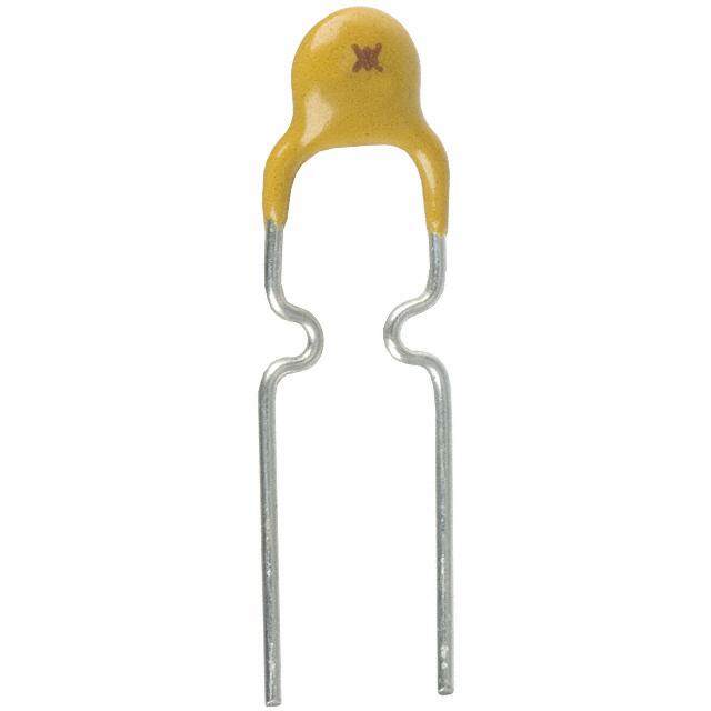
ICGOO电子元器件商城为您提供72R135XF由Littelfuse设计生产,在icgoo商城现货销售,并且可以通过原厂、代理商等渠道进行代购。 72R135XF价格参考。Littelfuse72R135XF封装/规格:PTC 可复位保险丝, 聚合物 PTC 自恢复保险丝 72V 1.35A Ih 通孔 径向,圆片式。您可以下载72R135XF参考资料、Datasheet数据手册功能说明书,资料中有72R135XF 详细功能的应用电路图电压和使用方法及教程。
Littelfuse Inc. 的 PTC 可复位保险丝型号 72R135XF 是一种过流保护器件,广泛应用于各种电子设备中,用于防止因过电流或短路引起的损坏。以下是其主要应用场景:

1. 消费类电子产品:适用于笔记本电脑、平板电脑、智能手机、数码相机等便携式设备的电源接口和电池充电电路保护,防止因外部电源异常或电池短路引发的问题。

2. 通信设备:用于路由器、交换机、调制解调器等网络设备的数据线和电源线保护,确保设备在过载或短路时不会受损。

3. 家用电器:如微波炉、洗衣机、冰箱等家电的控制电路保护,避免因电路故障导致的设备损坏或火灾风险。

4. 工业自动化设备:用于传感器、控制器、驱动器等工业设备的输入输出端口保护,保障设备运行的安全性和稳定性。

5. 汽车电子系统:适用于车载娱乐系统、导航设备、车窗升降模块等的电路保护,防止因电气故障导致的功能失效。

6. USB 接口保护:在 USB 充电或数据传输设备中,提供过流保护功能,防止因不合规的充电器或电缆导致的损坏。

7. 锂电池管理系统:用于保护锂离子电池组免受过充、过放或短路的影响,确保电池使用的安全性和寿命。

72R135XF 的典型特点包括低电阻值(约 0.135 Ω)、高保持电流(可达 1.8A)以及快速响应特性,使其能够在不影响正常工作电流的情况下,有效切断过大的电流,从而保护电路免受损害。此外,由于其可复位特性,相比传统一次性保险丝,能够显著降低维护成本并提高系统的可靠性。
| 参数 | 数值 |
| 产品目录 | |
| 描述 | PTC RESETTABLE 72V 1.35A RADIAL |
| 产品分类 | |
| 品牌 | Littelfuse Inc |
| 数据手册 | |
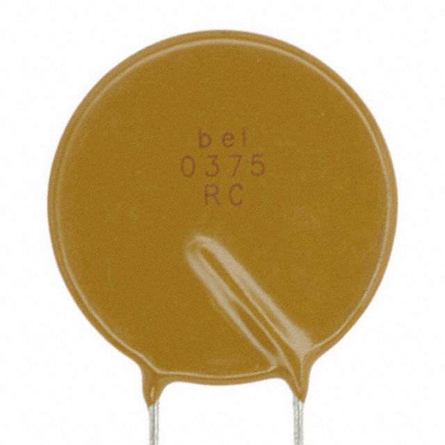
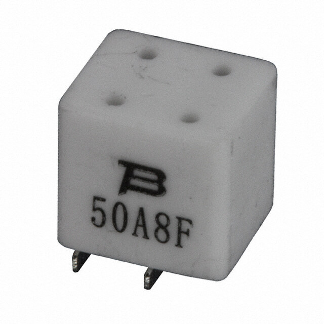
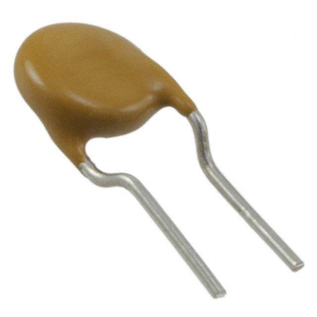
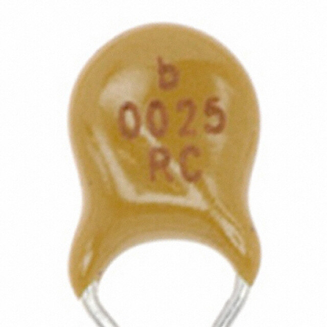
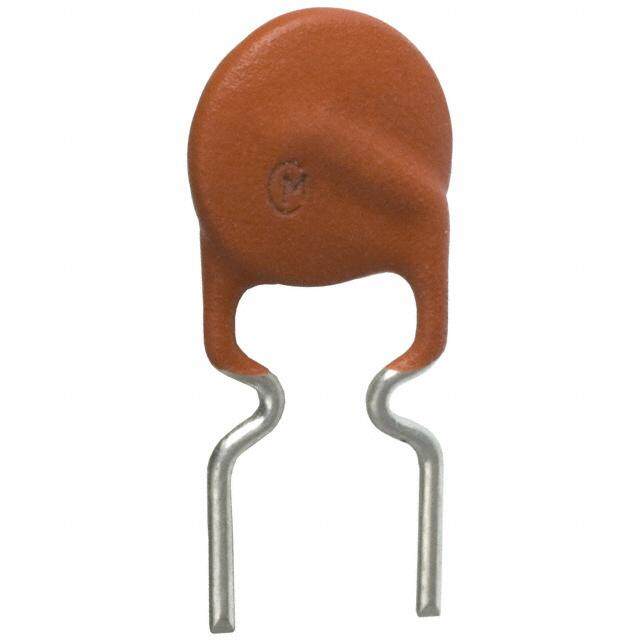
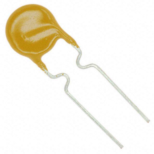
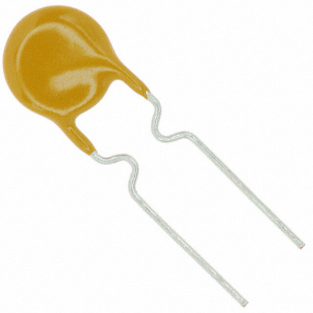
| 产品图片 |
|
| 产品型号 | 72R135XF |
| rohs | 无铅 / 符合限制有害物质指令(RoHS)规范要求 |
| R(最小/最大值) | 0.120 ~ 0.300 欧姆 |
| 产品系列 | POLYFUSE® 72R |
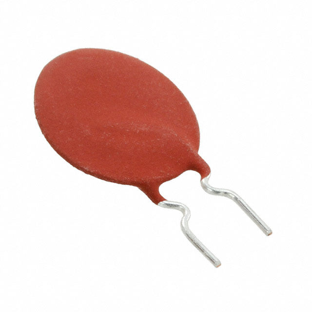
| 产品目录绘图 |
|
| 产品目录页面 | |
| 其它名称 | 72R135X |
| 包装 | 散装 |
| 封装/外壳 | 径向,圆盘 |
| 标准包装 | 200 |
| 特色产品 | http://www.digikey.com/cn/zh/ph/Littelfuse/72r.html |
| 电压-最大值 | 72V |
| 电流-保持(Ih)(最大值) | 1.35A |
| 电流-最大值 | 40A |
| 电流-跳闸(It) | 2.7A |
| 跳闸时间 | 9.6s |


135X%20Series.jpg)


PDF Datasheet 数据手册内容提取
POLY-FUSE® Resettable PTCs Radial Leaded > 72R Series 72R Series RoHS * Description The 72R Series is designed to provide overcurrent protection to 72Vdc maximum voltage with a maximum 40A short circuit rating. Features • 72Vdc max voltage w/max • Resettable feature 40A short circuit rating • Ideal for a broad range of • RoHS compliant, Lead-Free general electronics using a and Halogen Free* low voltage power supply Agency Approvals Applications AGENCY AGENCY FILE NUMBER • Load protection on wide • Computer peripherals range of low voltage power • General electronics E183209 supplies • Computers R50119318 Electrical Characteristics Maximum Time Agency I I V I Pd To Trip Resistance Approvals Part Number hold trip max max typ. (A) (A) (Vdc) (A) (W) Current Time R min R 1max (A) (Sec.) (Ω) (Ω) 72R020X 0.20 0.40 72 40 0.41 1.00 2.20 1.830 4.400 X X 72R025X 0.25 0.50 72 40 0.45 1.25 2.50 1.250 3.000 X X 72R030X 0.30 0.60 72 40 0.49 1.50 3.00 0.880 2.100 X X 72R040X 0.40 0.80 72 40 0.56 2.00 3.80 0.550 1.290 X X 72R050X 0.50 1.00 72 40 0.77 2.50 4.00 0.500 1.170 X X 72R065X 0.65 1.30 72 40 0.88 3.25 5.30 0.310 0.720 X X 72R075X 0.75 1.50 72 40 0.92 3.75 6.30 0.250 0.600 X X 72R090X 0.90 1.80 72 40 0.99 4.50 7.20 0.200 0.470 X X 72R110X 1.10 2.20 72 40 1.50 5.50 8.20 0.150 0.380 X X 72R135X 1.35 2.70 72 40 1.70 6.75 9.60 0.120 0.300 X X 72R160X 1.60 3.20 72 40 1.90 8.00 11.40 0.090 0.220 X X 72R185X 1.85 3.70 72 40 2.10 9.25 12.60 0.080 0.190 X X 72R250X 2.50 5.00 72 40 2.50 12.50 15.60 0.050 0.130 X X 72R300X 3.00 6.00 72 40 2.80 15.00 19.80 0.040 0.100 X X 72R375X 3.75 7.50 72 40 3.20 18.75 24.00 0.030 0.080 X X I = Hold current: maximum current device will pass without tripping in 20°C still air. R = Maximum resistance of device at 20°C measured one hour after tripping or reflow hold 1max I = Trip current: minimum current at which the device will trip in 20°C still air. soldering of 260°C for 20 sec. trip V = Maximum voltage device can withstand without damage at rated current (I max) Caution: Operation beyond the specified rating may result in damage and possible arcing max and flame. I = Maximum fault current device can withstand without damage at rated voltage (V ) max max P = Power dissipated from device when in the tripped state at 20°C still air. d R = Minimum resistance of device in initial (un-soldered) state. min * Effective January 1, 2010, all 72R PTC products will be manufactured Halogen Free (HF). Existing Non-Halogen Free 72R PTC products may continue to be sold, until supplies are depleted. © 2017 Littelfuse, Inc. Specifications are subject to change without notice. Revised: 03/22/17
POLY-FUSE® Resettable PTCs Radial Leaded > 72R Series Temperature Rerating Ambient Operation Temperature -40°C -20°C 0°C 20°C 40°C 50°C 60°C 70°C 85°C Part Number Hold Current (A) 72R020X 0.31 0.27 0.24 0.20 0.16 0.14 0.13 0.11 0.08 72R025X 0.39 0.34 0.30 0.25 0.20 0.18 0.16 0.14 0.10 72R030X 0.47 0.41 0.36 0.30 0.24 0.22 0.19 0.16 0.12 72R040X 0.62 0.54 0.48 0.40 0.32 0.29 0.25 0.22 0.16 72R050X 0.78 0.68 0.60 0.50 0.41 0.36 0.32 0.27 0.20 72R065X 1.01 0.88 0.77 0.65 0.53 0.47 0.41 0.35 0.26 72R075X 1.16 1.02 0.89 0.75 0.61 0.54 0.47 0.41 0.30 72R090X 1.40 1.22 1.07 0.90 0.73 0.65 0.57 0.49 0.36 72R110X 1.71 1.50 1.31 1.10 0.89 0.79 0.69 0.59 0.44 72R135X 2.09 1.84 1.61 1.35 1.09 0.97 0.85 0.73 0.54 72R160X 2.48 2.18 1.90 1.60 1.30 1.15 1.01 0.86 0.64 72R185X 2.87 2.52 2.20 1.85 1.50 1.33 1.17 1.00 0.74 72R250X 3.88 3.40 2.98 2.50 2.03 1.80 1.58 1.35 1.00 72R300X 4.65 4.08 3.57 3.00 2.43 2.16 1.89 1.62 1.20 72R375X 5.81 5.10 4.46 3.75 3.04 2.70 2.36 2.03 1.50 Average Time Current Curves Temperature Rerating Curve 0.75A1.20A1.55A0.90A1.10A1.35A1.60A1.85A2.50A USBR 2.5 A3.0 A4.0 A5.0 A6.0 A7.0 A8.0 A9.0 A10.0 A11.0 A12.0 A14.0 A 16R 0.90A1.10A1.35A1.60A1.85 A2.50A3.00A4.00A5.00A6.00A7.00A8.00A9.00A 30R 0.10A0.17A0.20A0.25A0.30A0.40A0.50A0.65A0.75A0.90AA1.101.35A1.60AA1.852.50AA3.003.75A60R 0.20A0.25A0.30A0.40A0.50A0.65A0.75A0.90A1.10A1.35A1.60A1.85A2.50A3.00A3.75A 72R 115700%% 0.080A0.120A0.145A0.180A 250R 0.15 A0.16 A 600R 100 100 100000 100 100 100000 100000 nt 130% e urr 10000 d C 110% 10000 ate 10000 10 of R 90% 10 10 10 ge 1000 nta 70% 1000 e me in Seconds 1 me in Seconds 1 me in Seconds 10100 me in Seconds 1 me in Seconds 1 Perc 531000%%%-40 -30 -20me in Seconds-1100100 0 10 20 30 40 50 60 70 80 me in Seconds1010000 Ti0.1 Ti Ti Ti Ti Ti Temperature (°C) Ti 10 1 1 0.1 0.1 0.1 Note: Typical Temperature rerating curve, refer to table for derating data 0.01 1 0.1 0.1 0.001 0.01 0.01 0.01 0.01 0.01 0.1 1 10 100 1000 1 10 100 1000 0.1 1 10 100 0.1 1 10 100 0.1 1 10 100 0.1 1 10 100 0.1 1 10 100 Current in Amperes Current in Amperes Current in Amperes Current in Amperes Current in Amperes Current in Amperes Current in Amperes The average time current curves and Temperature Rerating curve performance is affected by a number or variables, and these curves provided as guidance only. Customer must verify the performance in their application. © 2017 Littelfuse, Inc. Specifications are subject to change without notice. Revised: 03/22/17
POLY-FUSE® Resettable PTCs Radial Leaded > 72R Series Soldering Parameters - Wave Soldering Refer to the condition recommended by the flux manufacturer. Pre-Heating Zone Max. ramping rate should not exceed Soldering Cooling 260 4°C/Sec. 220 Max. solder temperature should not C) ° exceed 260°C e ( ur Preheating Time within 5°C of actual Max. solder erat 190 Soldering Zone temperature within 3 - 5 seconds mp 160 Te Total time from 25°C room to Max. solder temperature within 5 minutes including Pre-Heating time Cooling by natural convection in air. 0 60 min. 5 max. Cooling Zone Max. ramping down rate should not Time(s) exceed 6°C/Sec. Physical Specifications Environmental Specifications 0.20-0.40A: Tin-plated Copper clad steel Operating/Storage Lead Material -40°C to +85°C 0.50-3.75A: Tin-plated Copper Temperature Soldering Solderability per MIL–STD–202, Method Maximum Device Surface 125°C Characteristics 208 Temperature in Tripped State Cured, flame retardant epoxy polymer +85°C, 1000 hours Insulating Material Passive Aging meets UL 94V-0 requirements. -/+5% typical resistance change Lead Solderability Manadr kdeadte w ciothd e‘L.F’, voltage, current rating, Humidity Aging +-/+855°%C ,t 8yp5i%ca lR r.eHs.i s1t0a0n0c eh ochuarsnge +85°C to -40°C 10 times Additional Information Thermal Shock -/+5% typical resistance change Solvent Resistance MIL–STD–202, Method 215 Datasheet Resources SSaammpplleess Moistrue Sesitivity Level Level 1, J–STD–020 © 2017 Littelfuse, Inc. Specifications are subject to change without notice. Revised: 03/22/17
POLY-FUSE® Resettable PTCs Radial Leaded > 72R Series Dimensions Part Marking System Double Sided Marking 0.20A to 0.40A Single Sided Marking Top Side A E A E Littelfuse 72 Voltage Rating Littelfuse 72 Voltage Rating Trademark 020X Current Rating Trademark 020X Current Rating XXXX Date Code (Contact Littelfuse B for additional B information) D D C F Bottom Side C F Littelfuse 72 Voltage Rating Trademark XXXX Date Code (Contact Littelfuse A B C D E F Physical Characteristics for additional information) Part Inches mm Inches mm Inches mm Inches mm Inches mm Inches mm Lead (dia) Number Material Max. Max. Max. Max. Typ. Typ. Min. Min. Max. Max. Typ. Typ. Inches mm 72R020X 0.29 7.4 0.46 11.7 0.20 5.1 0.30 7.6 0.12 3.1 0.047 1.2 0.02 0.51 Sn/CuFe 72R025X 0.29 7.4 0.50 12.7 0.20 5.1 0.30 7.6 0.12 3.1 0.047 1.2 0.02 0.51 Sn/CuFe 72R030X 0.29 7.4 0.50 12.7 0.20 5.1 0.30 7.6 0.12 3.1 0.047 1.2 0.02 0.51 Sn/CuFe 72R040X 0.30 7.6 0.53 13.5 0.20 5.1 0.30 7.6 0.12 3.1 0.047 1.2 0.02 0.51 Sn/CuFe 72R050X 0.31 7.9 0.54 13.7 0.20 5.1 0.30 7.6 0.12 3.1 0.047 1.2 0.02 0.51 Sn/Cu 72R065X 0.37 9.4 0.57 14.5 0.20 5.1 0.30 7.6 0.12 3.1 0.047 1.2 0.02 0.51 Sn/Cu 72R075X 0.40 10.2 0.60 15.2 0.20 5.1 0.30 7.6 0.12 3.1 0.047 1.2 0.02 0.51 Sn/Cu 72R090X 0.44 11.2 0.62 15.8 0.20 5.1 0.30 7.6 0.12 3.1 0.047 1.2 0.02 0.51 Sn/Cu 72R110X 0.51 13.0 0.72 18.2 0.20 5.1 0.30 7.6 0.12 3.1 0.055 1.4 0.03 0.81 Sn/Cu 72R135X 0.53 13.58 0.78 19.8 0.20 5.1 0.30 7.6 0.12 3.1 0.055 1.4 0.03 0.81 Sn/Cu 72R160X 0.60 15.36 0.85 21.6 0.20 5.1 0.30 7.6 0.12 3.1 0.055 1.4 0.03 0.81 Sn/Cu 72R185X 0.66 16.76 0.91 23.0 0.20 5.1 0.30 7.6 0.12 3.1 0.055 1.4 0.03 0.81 Sn/Cu 72R250X 0.78 19.93 1.03 26.2 0.40 10.2 0.30 7.6 0.12 3.1 0.055 1.4 0.03 0.81 Sn/Cu 72R300X 0.91 23.11 1.15 29.3 0.40 10.2 0.30 7.6 0.12 3.1 0.055 1.4 0.03 0.81 Sn/Cu 72R375X 1.04 26.3 1.22 31.1 0.40 10.2 0.30 7.6 0.12 3.1 0.055 1.4 0.03 0.81 Sn/Cu © 2017 Littelfuse, Inc. Specifications are subject to change without notice. Revised: 03/22/17
POLY-FUSE® Resettable PTCs Radial Leaded > 72R Series Part Ordering Number System 72 R 090 X P R PACKAGING STYLE BLANK: Bulk R: Tape & Ammo SERIES QUANTITY CODE: F=200 H=100 M=1000 P=2000 U=500 TYPE: X (72VDC) I CURRENT CODE (Refer to Packaging or Electrical Characteristics tables) HOLD R: RADIAL VOLTAGE RATING (VDC) Packaging Ordering Part I I Packaging Quantity & Part Number hold hold Quantity Number (A) Code Option Packaging Codes 72R020XU Bulk 500 U 72R020X 0.20 020 72R020XPR Tape and Ammo 2000 PR 72R025XU Bulk 500 U 72R025X 0.25 025 72R025XPR Tape and Ammo 2000 PR 72R030XU Bulk 500 U 72R030X 0.30 030 72R030XPR Tape and Ammo 2000 PR 72R040XU Bulk 500 U 72R040X 0.40 040 72R040XPR Tape and Ammo 2000 PR 72R050XU Bulk 500 U 72R050X 0.50 050 72R050XPR Tape and Ammo 2000 PR 72R065XU Bulk 500 U 72R065X 0.65 065 72R065XPR Tape and Ammo 2000 PR 72R075XU Bulk 500 U 72R075X 0.75 075 72R075XPR Tape and Ammo 2000 PR 72R090XU Bulk 500 U 72R090X 0.90 090 72R090XPR Tape and Ammo 2000 PR 72R110XU Bulk 500 U 72R110X 1.10 110 72R110XMR Tape and Ammo 1000 MR 72R135XF Bulk 200 F 72R135X 1.35 135 72R135XMR Tape and Ammo 1000 MR 72R160XF Bulk 200 F 72R160X 1.60 160 72R160XMR Tape and Ammo 1000 MR 72R185XF Bulk 200 F 72R185X 1.85 185 72R185XMR Tape and Ammo 1000 MR 72R250XF Bulk 200 F 72R250X 2.50 250 72R250XMR Tape and Ammo 1000 MR 72R300XF Bulk 200 F 72R300X 3.00 300 72R300XMR Tape and Ammo 1000 MR 72R375X 72R375XH 3.75 375 Bulk 100 H © 2017 Littelfuse, Inc. Specifications are subject to change without notice. Revised: 03/22/17
POLY-FUSE® Resettable PTCs Radial Leaded > 72R Series Tape and Ammo Specifications Devices taped using EIA468-B/IE286-2 standards. See table below and Figure 1 for details. Dimensions Dimension EIA Mark IEC Mark Dim. (mm) Tol. (mm) Carrier tape width W W 18 –0.5 / +1.0 Hold down tape width W W 11 min. 4 0 Top distance between tape edges W W 3 max. 6 2 Sprocket hole position W W 9 –0.5 / +0.75 5 1 Sprocket hole diameter* D D 4 –0.32 / +0.2 0 0 Abscissa to plane (straight lead) H H 18.5 –/+ 3.0 Abscissa to plane (kinked lead) H H 16 –/+ 0.5 0 0 Abscissa to top 72R020X–72R090X H H 32.2 max. 1 1 Abscissa to top 72R110X–72R300X H 47.5 max. 1 Overall width without lead protrusion: C 42.5 max. 72R020X–72R090X 1 Overall width without lead protrusion: 57 72R110X–72R300X Overall width with lead protrusion: C 43.2 max. 72R020X–72R090X 2 Overall width with lead protrusion: 58 72R110X–72R300X Lead protrusion L l 1.0 max. 1 1 Protrusion of cut out L L 11 max. Protrusion beyond hold–down tape l l Not specified 2 2 Sprocket hole pitch: 72R020X–72R090X P P 12.7 –/+ 0.3 0 0 Sprocket hole pitch: 72R110X–72R300X P P 25.4 –/+ 0.5 0 0 20 Pitch tolerance –/+ 1 consecutive. Device pitch: 72R020X–72R090X 12.7 Device pitch: 72R110X–72R300X 25.4 Tape thickness t t 0.9 max. Tape thickness with splice t 2.0 max. 1 Splice sprocket hole alignment 0 –/+ 0.3 Body lateral deviation Δh Δh 0 –/+ 1.0 Body tape plane deviation Δp Δp 0 –/+ 1.3 Ordinate to adjacent component lead*: P P 3.81 –/+ 0.7 72R020X–72R090X 1 1 Ordinate to adjacent component lead*: 7.62 –/+ 0.7 72R110X–72R300X Lead spacing: 72R020X–72R185X F F 5.08 –/+ 0.8 Lead spacing: 72R250X–72R300X F F 10.18 –/+ 0.8 *Differs from EIA Specification © 2017 Littelfuse, Inc. Specifications are subject to change without notice. Revised: 03/22/17
POLY-FUSE® Resettable PTCs Radial Leaded > 72R Series Tape and Ammo Diagram Figure 1 ∆h ∆h ∆h ∆p Reference plane A H1 1 F H1 C1 H C 2 H L A B 0 W W 5 4 W I 2 L1 P0 D0 Direction of unreeling Cross section A - B t Reel Upper side Tape Direction of unreeling Lower side w 1 Cross section w Optional shape: Circular or polygonal 2 WARNING • Users shall independently assess the suitability of these devices for each of their applications • Operation of these devices beyond the stated maximum ratings could result in damage to the devices and lead to electrical arcing and/or fire • These devices are intended to protect against the effects of temporary over-current or over-temperature conditions and are not intended to perform as protective devices where such conditions are expected to be repetitive or prolonged in duration • Exposure to silicon-based oils, solvents, electrolytes, acids, and similar materials can adversely affect the performance of these PPTC devices • These devices undergo thermal expansion under fault conditions, and thus shall be provided with adequate space and be protected against mechanical stresses • Circuits with inductance may generate a voltage (L di/dt) above the rated voltage of the PPTC device. Disclaimer Notice - Information furnished is believed to be accurate and reliable. However, users should independently evaluate the suitability of and test each product selected for their own applications. Littelfuse products are not designed for, and may not be used in, all applications. Read complete Disclaimer Notice at www.littelfuse.com/disclaimer-electronics. © 2017 Littelfuse, Inc. Specifications are subject to change without notice. Revised: 03/22/17