ICGOO在线商城 > 电路保护 > PTC 可复位保险丝 > MF-SM030-2
 Datasheet下载
- 型号: MF-SM030-2
- 制造商: Bourns
- 库位|库存: xxxx|xxxx
- 要求:
| 数量阶梯 | 香港交货 | 国内含税 |
| +xxxx | $xxxx | ¥xxxx |
查看当月历史价格
查看今年历史价格
MF-SM030-2产品简介:
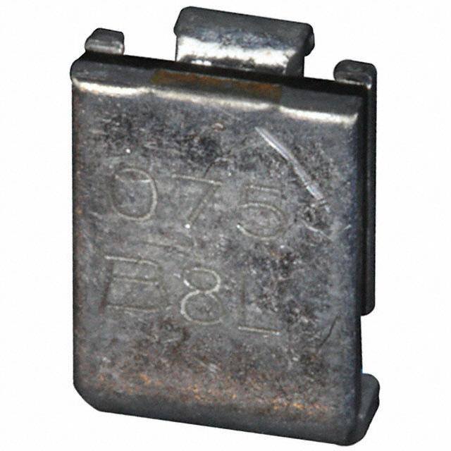
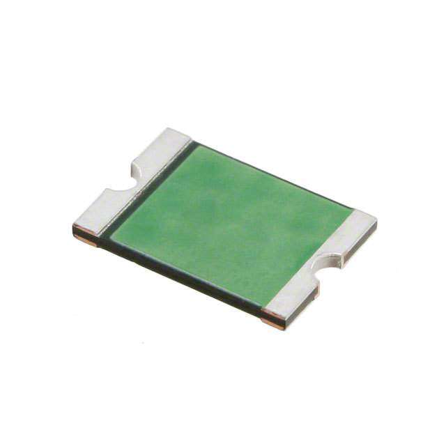
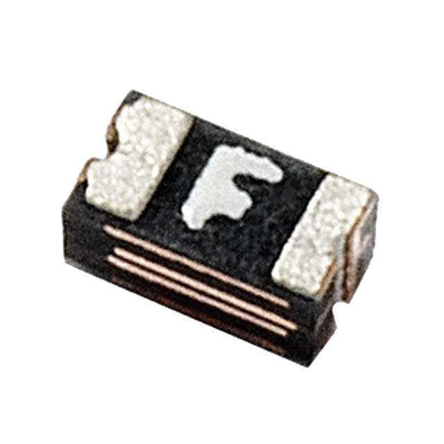
ICGOO电子元器件商城为您提供MF-SM030-2由Bourns设计生产,在icgoo商城现货销售,并且可以通过原厂、代理商等渠道进行代购。 MF-SM030-2价格参考¥1.08-¥1.13。BournsMF-SM030-2封装/规格:PTC 可复位保险丝, 聚合物 PTC 自恢复保险丝 60V 300mA Ih 表面贴装 2-SMD。您可以下载MF-SM030-2参考资料、Datasheet数据手册功能说明书,资料中有MF-SM030-2 详细功能的应用电路图电压和使用方法及教程。
Bourns Inc. 生产的 MF-SM030-2 是一款 PTC(正温度系数热敏电阻)可复位保险丝,广泛应用于各种电子设备中,提供过流和过温保护。具体应用场景如下:

1. 消费电子产品:例如手机、平板电脑、笔记本电脑等便携式设备中,MF-SM030-2 可以防止因电池短路或充电器故障引起的过电流问题。它能在异常情况下迅速响应,自动断开电路,避免设备损坏,并在故障排除后恢复正常工作。

2. 电源管理系统:在电源适配器、USB 充电器及电池管理模块中,该元件可以有效监控电流变化,确保系统安全运行。当检测到异常高电流时,PTC 保险丝会立即动作,切断电源供应,保护内部电路不受损害。

3. 工业控制设备:如电机驱动器、PLC 控制器等自动化装置中,MF-SM030-2 能够为敏感组件提供可靠的过载保护,延长设备使用寿命,提高系统的稳定性和可靠性。

4. 汽车电子:用于车载音响、导航系统以及辅助驾驶系统的电源输入端口,防止外部电压波动对内部电路造成冲击,保障行车安全。

5. 通信设备:在网络路由器、交换机等网络设备中,此型号的 PTC 保险丝能够抵御雷击、静电放电等瞬态干扰带来的危害,维持数据传输的连续性和完整性。

总之,MF-SM030-2 凭借其小巧的尺寸(SMD封装)、快速响应特性以及自我恢复功能,在众多领域内扮演着不可或缺的安全防护角色。它不仅有助于提升产品的整体性能和质量,还大大降低了维护成本和风险。
| 参数 | 数值 |
| 产品目录 | |
| 描述 | FUSE RESETTABLE .30A 60V SMD可复位保险丝—PPTC 0.30A 60V 0.90ohm Hold 0.3A Trip 0.6A |
| 产品分类 | |
| 品牌 | Bourns |
| 产品手册 | |
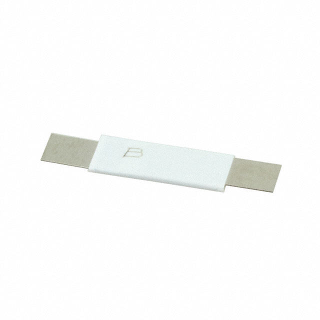
| 产品图片 |
|
| rohs | 符合RoHS无铅 / 符合限制有害物质指令(RoHS)规范要求 |
| 产品系列 | Bourns MF-SM030-2MF-SM |
| mouser_ship_limit | 该产品可能需要其他文件才能进口到中国。 |
| 数据手册 | |
| 产品型号 | MF-SM030-2 |
| PCN设计/规格 | |
| RoHS指令信息 | |
| R(最小/最大值) | 0.900 ~ 4.800 欧姆 |
| 产品培训模块 | http://www.digikey.cn/PTM/IndividualPTM.page?site=cn&lang=zhs&ptm=5252http://www.digikey.cn/PTM/IndividualPTM.page?site=cn&lang=zhs&ptm=4768 |
| 产品目录绘图 |
|
| 产品目录页面 | |
| 产品种类 | 可复位保险丝—PPTC |
| 保持电流 | 0.3 A |
| 其它名称 | MF-SM030-02 |
| 包装 | 带卷 (TR) |
| 商标 | Bourns |
| 商标名 | Multifuse |
| 安装风格 | SMD/SMT |
| 封装 | Reel |
| 封装/外壳 | 2-SMD |
| 封装/箱体 | 2920 (7351 metric) |
| 尺寸 | 7.98 mm L x 5.44 mm W x 3.18 mm H |
| 工作温度范围 | - 40 C to + 85 C |
| 工具箱 | /product-detail/zh/MF-SMLAB/MF-SMLAB-ND/2138812 |
| 工厂包装数量 | 2000 |
| 最大电压 | 60 VDC |
| 标准包装 | 2,000 |
| 电压-最大值 | 60V |
| 电流-保持(Ih)(最大值) | 300mA |
| 电流-最大值 | 40A |
| 电流-跳闸(It) | 600mA |
| 电阻 | 4.8 Ohms |
| 端接类型 | SMD/SMT |
| 类型 | PTC Resettable Fuses |
| 系列 | MF-SM |
| 跳闸时间 | 3s |
| 跳闸电流 | 0.6 A |
| 额定电流—最大值 | 40 A |


- 商务部:美国ITC正式对集成电路等产品启动337调查
- 曝三星4nm工艺存在良率问题 高通将骁龙8 Gen1或转产台积电
- 太阳诱电将投资9.5亿元在常州建新厂生产MLCC 预计2023年完工
- 英特尔发布欧洲新工厂建设计划 深化IDM 2.0 战略
- 台积电先进制程称霸业界 有大客户加持明年业绩稳了
- 达到5530亿美元!SIA预计今年全球半导体销售额将创下新高
- 英特尔拟将自动驾驶子公司Mobileye上市 估值或超500亿美元
- 三星加码芯片和SET,合并消费电子和移动部门,撤换高东真等 CEO
- 三星电子宣布重大人事变动 还合并消费电子和移动部门
- 海关总署:前11个月进口集成电路产品价值2.52万亿元 增长14.8%


PDF Datasheet 数据手册内容提取
NT *RoHS VCEOARVMSIAPILOLINAASBLE NT MPLIA O HS C Ro * REE D F LEA LVEEARDH SISF ORCNEOSE MAPRLIE ANT* Ro NT *Ro&H SA ECCO AMPPPLIRAOVED REE N F GE O NT, **MHPALLIANT AE*C-RQo2H0S 0 aCnOd MPLIANT Fnn eCTiSnaeou tsAmrutfu apQrtcoleueiam asnmloitfi otwicuvaientth tiAo dApneEp vfCloiicc-reQ aPst2iao0sn0ss ivRee vC-oCm- Spotrneesnst s nnn RAPgaoteHennSct ysc orpemecnpodlgiiannngitti*o na:n d halog*eRonH Sf rCeOeMP*&L I*AAEC CO 77AA n Fully compatible with current industry standards n Packaged per EIA 481-2 standard MF-SM Series - PTC Resettable Fuses Electrical Characteristics Tripped Max. Time Ihold Itrip Resistance To Trip Power V max. I max Dissipation Model Volts Amps Amperes Ohms Amperes Seconds Watts at 23 °C at 23 °C at 23 °C at 23 °C at 23 °C Hold Trip R Min. R1 Max. Max. Typ. MF-SM030 60 40 0.30 0.60 0.90 4.80 1.5 3.0 1.7 MF-SM050 60 40 0.50 1.00 0.35 1.40 2.5 4.0 1.7 MF-SM075 30 80 0.75 1.50 0.23 1.00 8.0 0.3 1.7 MF-SM075/60 60 10 0.75 1.50 0.23 1.00 8.0 0.3 1.7 MF-SM100 30 80 1.10 2.20 0.12 0.48 8.0 0.5 1.7 MF-SM100/33 33 40 1.10 2.20 0.12 0.41 8.0 0.5 1.7 MF-SM125 15 100 1.25 2.50 0.07 0.25 8.0 2.0 1.7 MF-SM150 15 100 1.50 3.00 0.06 0.25 8.0 5.0 1.9 MF-SM150/33 33 40 1.50 3.00 0.06 0.23 8.0 5.0 1.9 MF-SM185/33 33 40 1.80 3.60 0.04 0.15 8.0 5.0 1.9 MF-SM200 15 100 2.00 4.00 0.045 0.125 8.0 12.0 1.9 MF-SM250 15 100 2.50 5.00 0.024 0.085 8.0 25.0 1.9 MF-SM260 6 100 2.60 5.20 0.025 0.075 8.0 20.0 1.7 MF-SM300 6 100 3.00 6.00 0.015 0.048 8.0 35.0 1.5 Environmental Characteristics Operating Temperature .........................................-40 °C to +85 °C Maximum Device Surface Temperature in Tripped State ....................................................125 °C Passive Aging .......................................................+85 °C, 1000 hours ...............................................±5 % typical resistance change Humidity Aging......................................................+85 °C, 85 % R.H. 7 days .....................................±5 % typical resistance change Thermal Shock .....................................................MIL-STD-202F, Method 107G ...............................±10 % typical resistance change ..............................................................................-40 °C to +85 °C, 20 cycles ..................................-20 % typical resistance change Vibration ...............................................................MIL-STD-883C, Method 2007.1, ...........................Rmin ≤ R ≤ R1max Condition A Moisture Sensitivity Level (MSL) ..........................Level 1 ESD Classification - HBM .....................................Class 6 Test Procedures And Requirements For Model MF-SM Series Test Test Conditions Accept/Reject Criteria Visual/Mech. .....................................................Verify dimensions and materials .......................Per MF physical description Resistance ........................................................In still air @ 23 °C .............................................Rmin ≤ R ≤ R1max Time to Trip .......................................................At specified current, Vmax, 23 °C ....................T ≤ max. time to trip (seconds) Hold Current .....................................................30 min. at Ihold .................................................No trip Trip Cycle Life ...................................................Vmax, Imax, 100 cycles ...................................No arcing or burning Trip Endurance .................................................Vmax, 48 hours ................................................No arcing or burning Solderability ......................................................MIL-STD-202F, Method 208F ...........................95 % min. coverage UL File Number ................................................E174545 http://www.ul.com/ Follow link to Online Certificates Directory, then enter UL File No. E174545, or click here TÜV Certificate .................................................Certificate Number Available on Request, or click here * RoHS Directive 2002/95/EC Jan. 27, 2003 including annex and RoHS Recast 2011/65/EU June 8, 2011. **Bourns considers a product to be “halogen free” if (a) the Bromine (Br) content is 900 ppm or less; (b) the Chlorine (Cl) content is 900 ppm or less; and (c) the total Bromine (Br) and Chlorine (Cl) content is 1500 ppm or less. Specifications are subject to change without notice. Users should verify actual device performance in their specific applications. The products described herein and this document are subject to specific legal disclaimers as set forth on the last page of this document, and at www.bourns.com/docs/legal/disclaimer.pdf.
Applications Almost anywhere there is a low voltage power supply and a load to be protected, including: n Computers & peripherals n General electronics n Automotive applications MF-SM Series - PTC Resettable Fuses Product Dimensions Model A B C D E F G H Min. Max. Max. Max. Min. Max. Min. Max. Min. Max. Min. Max. Min. 6.73 7.98 3.18 5.44 0.56 0.71 0.56 0.71 2.16 2.41 0.66 1.37 0.43 MF-SM030 (0.265) (0.314) (0.125) (0.214) (0.022) (0.028) (0.022) (0.028) (0.085) (0.095) (0.026) (0.054) (0.017) 6.73 7.98 3.18 5.44 0.56 0.71 0.56 0.71 2.16 2.41 0.66 1.37 0.43 MF-SM050 (0.265) (0.314) (0.125) (0.214) (0.022) (0.028) (0.022) (0.028) (0.085) (0.095) (0.026) (0.054) (0.017) 6.73 7.98 3.18 5.44 0.56 0.71 0.56 0.71 2.16 2.41 0.66 1.37 0.43 MF-SM075 (0.265) (0.314) (0.125) (0.214) (0.022) (0.028) (0.022) (0.028) (0.085) (0.095) (0.026) (0.054) (0.017) 6.73 7.98 3.18 5.44 0.56 0.71 0.56 0.71 2.16 2.41 0.66 1.37 0.43 MF-SM075/60 (0.265) (0.314) (0.125) (0.214) (0.022) (0.028) (0.022) (0.028) (0.085) (0.095) (0.026) (0.054) (0.017) 6.73 7.98 3.0 5.44 0.56 0.71 0.56 0.71 2.16 2.41 0.66 1.37 0.43 MF-SM100 (0.265) (0.314) (0.118) (0.214) (0.022) (0.028) (0.022) (0.028) (0.085) (0.095) (0.026) (0.054) (0.017) 6.73 7.98 3.0 5.44 0.56 0.71 0.56 0.71 2.16 2.41 0.66 1.37 0.43 MF-SM100/33 (0.265) (0.314) (0.118) (0.214) (0.022) (0.028) (0.022) (0.028) (0.085) (0.095) (0.026) (0.054) (0.017) 6.73 7.98 3.0 5.44 0.56 0.71 0.56 0.71 2.16 2.41 0.66 1.37 0.43 MF-SM125 (0.265) (0.314) (0.118) (0.214) (0.022) (0.028) (0.022) (0.028) (0.085) (0.095) (0.026) (0.054) (0.017) 8.00 9.50 3.0 6.71 0.56 0.71 0.56 0.71 3.68 3.94 0.66 1.37 0.43 MF-SM150 (0.315) (0.374) (0.118) (0.264) (0.022) (0.028) (0.022) (0.028) (0.145) (0.155) (0.026) (0.054) (0.017) 8.00 9.50 3.0 6.71 0.56 0.71 0.56 0.71 3.68 3.94 0.66 1.37 0.43 MF-SM150/33 (0.315) (0.374) (0.118) (0.264) (0.022) (0.028) (0.022) (0.028) (0.145) (0.155) (0.026) (0.054) (0.017) 8.00 9.50 3.0 6.71 0.56 0.71 0.56 0.71 3.68 3.94 0.66 1.37 0.43 MF-SM185/33 (0.315) (0.374) (0.118) (0.264) (0.022) (0.028) (0.022) (0.028) (0.145) (0.155) (0.026) (0.054) (0.017) 8.00 9.50 3.0 6.71 0.56 0.71 0.56 0.71 3.68 3.94 0.66 1.37 0.43 MF-SM200 (0.315) (0.374) (0.118) (0.264) (0.022) (0.028) (0.022) (0.028) (0.145) (0.155) (0.026) (0.054) (0.017) 8.00 9.50 3.0 6R.7e1co mme0n.d5e6d Pad 0L.a7y1o ut 0.56 0.71 3.68 3.94 0.66 1.37 0.43 M F-SM250 (0.315) (0.374) (0.118) (0.M2F6-4S)M 0(300.,0 02520), 07(50,. 007258/6) 0, (100.00, 2120)0 /33(0, .102258, 2) 60(, 03.01045) (0.155) (0.026) (0.054) (0.017) MF-SM260 6.73 7.98 3.0 5.44 0.56 2.30 ±. 70.11 0.56 0.71 2.16 2.41 0.66 1.37 0.43 (0.265) (0.314) (0.118) (0.214) (0.022) (0.(009 .±0 02.0804)) (0.022) (0.028) (0.085) (0.095) (0.026) (0.054) (0.017) 6.73 7.98 3.0 5.44 0.56 0.71 0.56 0.71 2.16 2.41 0.66 1.37 0.43 MF-SM300 (0.265) (0.314) (0.118) (0.214) (0.022) (0.028) (0.022) (0.028) (0.085) (0.095) (0.026) (0.054) (0.017) Packaging: TAPE & REEL: MF-SM030, 050, 075, 075/60, 100, 100/33, 125, 260, 300 = 2000 pcs. per reel; MF-SM150, 150/33, 185/33, 200, 250 = 1500 pcs. per reel. How to Order 9.7 ± 0.1 DIMENSIONS: (INCMCHM(0E.13S2.)1 ±± 0 0.0.G104) (0.38 ± 0.C004) (0.132.1 ±±G 0 0.0.104) Multifuse® ProducMt F - SM 100/33 - 2 - 99 B B Designator Terminal material: Series Tin-plated brasFs F SM = Surface Mount Component H H D A DE A EnEd View End View Hold0 3C0u r-r e3n0t0, I(h0o.3ld -/ V3m.0a Axm* ps) Side View Side View Packaging Options - 2 = Tape and Reel** Recommended Pad Layout Recommended Pad Layout Part Number Suffix Option MF-SM030, 050, 075, 075/60, 100, 100/33, 125, 260, 300 MF-SM150, 150/33, 185/33, 200, 250 - 99 = RoHS Compliancy As of date code April 1, 2005 all 2.3 ± 0.1 2.3 ± 0.1 MF-SM models are RoHS compliant. (0.09 ± 0.004) (0.09 ± 0.004) The suffix “-99” can be used if a new part number is required to reference the RoHS compliance, but including the “-99” suffix option is not recommended for new designs. * Vmax entry applies only to models 9.7 ± 0.1 MF-SM075/60, MF-SM100/33, MF-SM150/33 (0.38 ± 0.004) & MF-SM185/33. 3.1 ± 0.1 3.1 ± 0.1 10.7 ± 0.1 ** Packaged per EIA-481-2 (0.12 ± 0.004) (0.12 ± 0.004) (0.42 ± 0.004) 4.6 ± 0.1 4.6 ± 0.1 (0.18 ± 0.004) (0.18 ± 0.004) Specifications are subject to change without notice. Users should verify actual device performance in their specific applications. The products described herein and this document are subject to specific legal disclaimers as set forth on the last page of this document, and at www.bourns.com/docs/legal/disclaimer.pdf. Recommended Pad Layout MF-SM150, 150/33, 185/33, 200, 250 2.3 ± 0.1 (0.09 ± 0.004) 10.7 ± 0.1 (0.42 ± 0.004) 4.6 ± 0.1 4.6 ± 0.1 (0.18 ± 0.004) (0.18 ± 0.004)
MF-SM Series - PTC Resettable Fuses Thermal Derating Chart - Ihold (Amps) Ambient Operating Temperature Model -40 ºC -20 ºC 0 ºC 23 ºC 40 ºC 50 ºC 60 ºC 70 ºC 85 ºC MF-SM030 0.45 0.40 0.35 0.30 0.25 0.23 0.20 0.17 0.14 MF-SM050 0.76 0.67 0.59 0.50 0.42 0.38 0.33 0.29 0.23 MF-SM075 1.11 0.99 0.84 0.75 0.63 0.57 0.49 0.45 0.36 MF-SM075/60 1.11 0.99 0.84 0.75 0.63 0.57 0.49 0.45 0.36 MF-SM100 1.66 1.47 1.29 1.10 0.91 0.83 0.73 0.64 0.50 MF-SM100/33 1.66 1.47 1.29 1.10 0.91 0.83 0.73 0.64 0.50 MF-SM125 1.89 1.68 1.46 1.25 1.04 0.94 0.83 0.73 0.56 MF-SM150 2.27 2.01 1.76 1.50 1.25 1.13 0.99 0.87 0.68 MF-SM150/33 2.27 2.01 1.76 1.50 1.25 1.13 0.99 0.87 0.68 MF-SM185/33 2.56 2.32 2.08 1.85 1.60 1.44 1.28 1.12 0.88 MF-SM200 3.02 2.68 2.34 2.00 1.66 1.50 1.32 1.16 0.90 MF-SM250 3.78 3.35 2.93 2.50 2.08 1.88 1.65 1.45 1.13 MF-SM260 3.64 3.25 2.91 2.60 2.26 2.08 1.95 1.74 1.48 MF-SM300 4.13 3.75 3.30 2.87 2.62 2.43 2.25 2.00 1.78 Itrip is approximately two times Ihold. Typical Time to Trip at 23 °C Typical Part Marking 3 075/60M100/3 150/33 Represents total content. Layout may vary. M S M MANUFACTURER'S PART IDENTIFICATION MF-SM030MF-SM05M0F-SM075,M F-MFS-MS10MF0,- SMMF-M1F8-5S/3M31M2F5-SM15M0,F -SMFM-2S0M0F-SM25M0F-SM30M0F-SM260 TRADEMARK 0370A DW(WYAEEETEEAEKKR C 12&O 7O D WOFE FE2 -E02K10)71 7= =7 AA7 (WEEK & YEAR) 100 10 s) d n o c e 1 S p ( Tri o e t 0.1 m Ti 0.01 0.001 0.1 1 10 100 Fault Current (Amps) Specifications are subject to change without notice. Users should verify actual device performance in their specific applications. The products described herein and this document are subject to specific legal disclaimers as set forth on the last page of this document, and at www.bourns.com/docs/legal/disclaimer.pdf.
MF-SM Series - PTC Resettable Fuses Solder Reflow Recommendations 300 Preheating Soldering Cooling Solder reflow 250 • Recommended reflow methods: IR, vapor phase oven, hot air oven. • Devices are not designed to be wave soldered to the bottom side of the 200 board. mperature (C)ϒ 115000 ••• GRDeelucvinoicgme stmh ceea ndnde bevedic cmelsea aixsni mneodut m ures picnaogsm tsemt athenindcdakenrdde .sinsd iuss 0tr.y2 5m emthmo d(.s0 1a0n din scohl)v.ents. Te Note: 50 • If reflow temperatures exceed the recommended profile, devices may not meet the performance requirements. 0 Rework 160–220 10–20 120 • A device should not be reworked. Time (seconds) Storage Recommendations The recommended long term storage conditions for Multifuse® Polymer PTC devices are 40 °C maximum and 70 % RH maximum. All devices should remain in the original sealed packaging prior to use. Devices may not conform with data sheet specifications if these storage recommendations are exceeded. Devices stored in this manner have an indefinite shelf life. MF-SM SERIES, REV. V, 10/17 Specifications are subject to change without notice. Users should verify actual device performance in their specific applications. The products described herein and this document are subject to specific legal disclaimers as set forth on the last page of this document, and at www.bourns.com/docs/legal/disclaimer.pdf.
MF-SM, MF-SM/33, MF-SM/60 & MF-SM/250 Series Tape and Reel Specifications NOTE: Effective December 1, 2010 (product date code V0), the cover tape was changed to the new 3M™ Universal Cover Tape (UCT). MF-SM030, 050, 075, 100, 125, 260, 300; MF-SM150, 200, 250; MF-SM075/60; MF-SM-100/33; MF-SM008/250 MF-SM-150/33, MF-SM-185/33; Tape Dimensions per EIA-481-2 MF-SM013/250 per EIA 481-2 16.3 16.3 W max. (0.642) (0.642) 4.0 ± 0.1 4.0 ± 0.1 P 0 (0.157 ± 0.004) (0.157 ± 0.004) 8.0 ± 0.1 12.0 ± 0.1 P 1 (0.315 ± 0.004) (0.472 ± 0.004) 2.0 ± 0.1 2.0 ± 0.1 P 2 (0.079 ± 0.004) (0.079 ± 0.004) 5.7 ± 0.1 6.9 ± 0.1 A 0 (0.224 ± 0.004) (0.272 ± 0.004) 8.1 ± 0.1 9.6 ± 0.1 B 0 (0.319 ± 0.004) (0.378 ± 0.004) 12.1 12.1 B1 max. (0.476) (0.476) 1.5 + 0.1/-0.0 1.5 + 0.1/-0.0 D 0 (0.059 + 0.004/-0) (0.059 + 0.004/-0) 7.5 ± 0.1 7.5 ± 0.1 F (0.295 + 0.004) (0.295 + 0.004) 1.75 ± 0.1 1.75 ± 0.1 E 1 (0.069 ± 0.004) (0.069 ± 0.004) 14.25 14.25 E2 min. (0.561) (0.561) 0.6 0.6 T max. (0.024) (0.024) 0.1 0.1 T1 max. (0.004) (0.004) 3.4 ± 0.1 3.4 ± 0.1* K 0 (0.134 ± 0.004) (0.134 ± 0.004)* 390 390 Leader min. (15.35) (15.35) 160 160 Trailer min. (6.30) (6.30) Reel Dimensions 360 360 A max. (14.17) (14.17) 50 50 N min. (1.97) (1.97) 16.4 + 2.0/ -0.0 16.4 + 2.0/ -0.0 MM W 1 (0.646 + 0.079/-0) (0.646 + 0.079/-0) DIMENSIONS: (INCHES) W2 max. (02.28.842) (02.28.842 ) 3.8 ± 0.1 *Model MF-SM013/250 = MM (0.150 ± 0.004) DIMENSIONS: (INCHES) P0 T D0 P2 E1 W2(MEASURED AT HUB) COVER TAPE F A N(HUB DIA.) E2W B1 B0 K0 P1 W1(AMT EHAUSBU)RED T1 A0 Specifications are subject to change without notice. Users should verify actual device performance in their specific applications. The products described herein and this document are subject to specific legal disclaimers as set forth on the last page of this document, and at www.bourns.com/docs/legal/disclaimer.pdf.
Legal Disclaimer Notice This legal disclaimer applies to purchasers and users of Bourns® products manufactured by or on behalf of Bourns, Inc. and its affiliates (collectively, “Bourns”). Unless otherwise expressly indicated in writing, Bourns® products and data sheets relating thereto are subject to change without notice. Users should check for and obtain the latest relevant information and verify that such information is current and complete before placing orders for Bourns® products. The characteristics and parameters of a Bourns® product set forth in its data sheet are based on laboratory conditions, and statements regarding the suitability of products for certain types of applications are based on Bourns’ knowledge of typical requirements in generic applications. The characteristics and parameters of a Bourns® product in a user application may vary from the data sheet characteristics and parameters due to (i) the combination of the Bourns® product with other components in the user’s application, or (ii) the environment of the user application itself. The characteristics and parameters of a Bourns® product also can and do vary in different applications and actual performance may vary over time. Users should always verify the actual performance of the Bourns® product in their specific devices and applications, and make their own independent judgments regarding the amount of additional test margin to design into their device or application to compensate for differences between laboratory and real world conditions. Unless Bourns has explicitly designated an individual Bourns® product as meeting the requirements of a particular industry standard (e.g., ISO/TS 16949) or a particular qualification (e.g., UL listed or recognized), Bourns is not responsible for any failure of an individual Bourns® product to meet the requirements of such industry standard or particular qualification. Users of Bourns® products are responsible for ensuring compliance with safety-related requirements and standards applicable to their devices or applications. Bourns® products are not recommended, authorized or intended for use in nuclear, lifesaving, life-critical or life-sustaining applications, nor in any other applications where failure or malfunction may result in personal injury, death, or severe property or environmental damage. Unless expressly and specifically approved in writing by two authorized Bourns representatives on a case-by-case basis, use of any Bourns® products in such unauthorized applications might not be safe and thus is at the user’s sole risk. Life-critical applications include devices identified by the U.S. Food and Drug Administration as Class III devices and generally equivalent classifications outside of the United States. Bourns expressly identifies those Bourns® standard products that are suitable for use in automotive applications on such products’ data sheets in the section entitled “Applications.” Unless expressly and specifically approved in writing by two authorized Bourns representatives on a case-by-case basis, use of any other Bourns® standard products in an automotive application might not be safe and thus is not recommended, authorized or intended and is at the user’s sole risk. If Bourns expressly identifies a sub-category of automotive application in the data sheet for its standard products (such as infotainment or lighting), such identification means that Bourns has reviewed its standard product and has determined that if such Bourns® standard product is considered for potential use in automotive applications, it should only be used in such sub-category of automotive applications. Any reference to Bourns® standard product in the data sheet as compliant with the AEC-Q standard or “automotive grade” does not by itself mean that Bourns has approved such product for use in an automotive application. Bourns® standard products are not tested to comply with United States Federal Aviation Administration standards generally or any other generally equivalent governmental organization standard applicable to products designed or manufactured for use in aircraft or space applications. Bourns expressly identifies Bourns® standard products that are suitable for use in aircraft or space applications on such products’ data sheets in the section entitled “Applications.” Unless expressly and specifically approved in writing by two authorized Bourns representatives on a case-by-case basis, use of any other Bourns® standard product in an aircraft or space application might not be safe and thus is not recommended, authorized or intended and is at the user’s sole risk. The use and level of testing applicable to Bourns® custom products shall be negotiated on a case-by-case basis by Bourns and the user for which such Bourns® custom products are specially designed. Absent a written agreement between Bourns and the user regarding the use and level of such testing, the above provisions applicable to Bourns® standard products shall also apply to such Bourns® custom products. Users shall not sell, transfer, export or re-export any Bourns® products or technology for use in activities which involve the design, development, production, use or stockpiling of nuclear, chemical or biological weapons or missiles, nor shall they use Bourns® products or technology in any facility which engages in activities relating to such devices. The foregoing restrictions apply to all uses and applications that violate national or international prohibitions, including embargos or international regulations. Further, Bourns® products and Bourns technology and technical data may not under any circumstance be exported or re-exported to countries subject to international sanctions or embargoes. Bourns® products may not, without prior authorization from Bourns and/or the U.S. Government, be resold, transferred, or re-exported to any party not eligible to receive U.S. commodities, software, and technical data. To the maximum extent permitted by applicable law, Bourns disclaims (i) any and all liability for special, punitive, consequential, incidental or indirect damages or lost revenues or lost profits, and (ii) any and all implied warranties, including implied warranties of fitness for particular purpose, non-infringement and merchantability. For your convenience, copies of this Legal Disclaimer Notice with German, Spanish, Japanese, Traditional Chinese and Simplified Chinese bilingual versions are available at: Web Page: http://www.bourns.com/legal/disclaimers-terms-and-policies PDF: http://www.bourns.com/docs/Legal/disclaimer.pdf C1753 05/17/18R