ICGOO在线商城 > 6331G11

 Datasheet下载
- 型号: 6331G11
- 制造商: ANDERSON POWER PRODUCTS
- 库位|库存: xxxx|xxxx
- 要求:
| 数量阶梯 | 香港交货 | 国内含税 |
| +xxxx | $xxxx | ¥xxxx |
查看当月历史价格
查看今年历史价格
6331G11产品简介:
ICGOO电子元器件商城为您提供6331G11由ANDERSON POWER PRODUCTS设计生产,在icgoo商城现货销售,并且可以通过原厂、代理商等渠道进行代购。 提供6331G11价格参考¥24.96-¥45.34以及ANDERSON POWER PRODUCTS6331G11封装/规格参数等产品信息。 你可以下载6331G11参考资料、Datasheet数据手册功能说明书, 资料中有6331G11详细功能的应用电路图电压和使用方法及教程。
| 参数 | 数值 |
| 品牌 | Anderson Power Products |
| 产品目录 | 连接器 |
| 描述 | 重负荷电源连接器 SB50 ORANGE #6 AWG 50A 6 AWG CONT |
| 产品分类 | 电源连接器 |
| 产品手册 | |
| 产品图片 |
|
| rohs | 符合RoHS |
| 产品系列 | 重负荷电源连接器,Anderson Power Products 6331G11 |
| 产品型号 | 6331G11 |
| 产品种类 | 重负荷电源连接器 |
| 商标 | Anderson Power Products |
| 工厂包装数量 | 50 |


- 商务部:美国ITC正式对集成电路等产品启动337调查
- 曝三星4nm工艺存在良率问题 高通将骁龙8 Gen1或转产台积电
- 太阳诱电将投资9.5亿元在常州建新厂生产MLCC 预计2023年完工
- 英特尔发布欧洲新工厂建设计划 深化IDM 2.0 战略
- 台积电先进制程称霸业界 有大客户加持明年业绩稳了
- 达到5530亿美元!SIA预计今年全球半导体销售额将创下新高
- 英特尔拟将自动驾驶子公司Mobileye上市 估值或超500亿美元
- 三星加码芯片和SET,合并消费电子和移动部门,撤换高东真等 CEO
- 三星电子宣布重大人事变动 还合并消费电子和移动部门
- 海关总署:前11个月进口集成电路产品价值2.52万亿元 增长14.8%


PDF Datasheet 数据手册内容提取
SBS® Connectors - up to 110 amps The patented SBS® connector family is designed to provide high power in a compact ergonomic housing with protection against accidental contact with live circuits. SBS®75G This is of particular importance in applications where DC voltages exceed 30 volts and can be health threatening. SBS®75X Wire to Wire Wire-to-wire and wire-to-board configurations both provide power contacts rated up to 110 amps. The SBS®75X offers up to 4 mate-last break-first auxiliary power / signal contacts rated up to 20 amps. The SBS®75G features a third first-mate last-break ground or power contact. All contact positions are rated for circuit interruption (hot plugging). • Touch Safe Interface - Can safely be used in through panel applications - Minimizes potential contact with live circuits per IEC 60950 • Wire-to-Wire and Wire-to-Board Configurations Allows one connector to meet multiple needs SBS®50 • Ground or Auxiliary Positions Integrated into the One Piece Housing Meets all connection requirements in one compact SS connector housing BE SC ® 5T | SBS® ORDERING INFORMATION | 0IO & N SBS®50 Standard Housings 75 3 Polycarbonate housings feature 2 positions all finger proof. Genderless design mates with itself. Mechanical keys are color coded. Description ----------- Part Numbers ----------- [ 19.1 ] Minimum Quantity ...... 500 50 ... [ 3.6 ] 0.75 [ 6.3 ] Red SBS50RED-BK SBS50RED 0.14 (2) 0.25 Gray SBS50GRA-BK SBS50GRA Blue SBS50BLU-BK SBS50BLU Black SBS50BLK-BK SBS50BLK Brown SBS50BRN-BK SBS50BRN [ 36.1 ] White SBS50WHT-BK SBS50WHT 1.42 [ 18.0 ] 0.71 SBS®50 Chemical Resistant (CR) Housings Same features as the standard housings, but molded out of a Material ID P = Chemical Resistant chemical resistant PBT/ PC blend. Suitable for use to -40°C. [ 55.8 ] Description ------------ Part Numbers ------------- 2.20 Minimum Quantity ...... 500 50 ... Red PSBS50RED-BK PSBS50RED [ 16.5 ] Gray PSBS50GRA-BK PSBS50GRA 0.65 Blue PSBS50BLU-BK PSBS50BLU Green PSBS50GRN-BK PSBS50GRN [84.8] Black PSBS50BLK-BK PSBS50BLK 3.34 Brown PSBS50BRN-BK PSBS50BRN © 2018 Anderson Power Products, Inc. All rights reserved. APP®, Anderson Power Products®, A®, SBS® and the APP Logo are registered trademarks of Anderson Power Products, Inc. - 57 - All Data Subject To Change Without Notice www.andersonpower.com
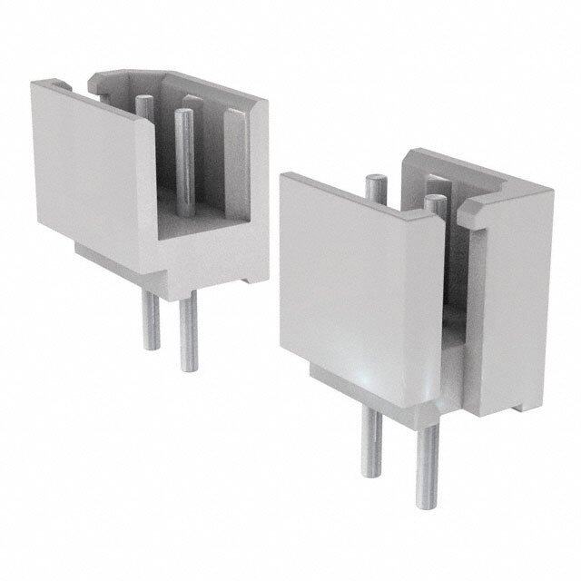
SBS®75X Standard Housings Polycarbonate housings feature 4 auxiliary and 2 primary positions Front View all finger proof. Genderless design mates with itself, or the PCB Primary Power Contacts connector. Mechanical keys are color coded. Description ------------ Part Numbers ------------- [ 15.2 ] 0.60 Minimum Quantity ..... 250 50 ... Black SBS75XBLK-BK SBS75XBLK Pin Socket Brown SBS75XBRN-BK SBS75XBRN [ 46.0 ] 1.81 SBS®75X Chemical Resistant (CR) Housings Bottom View Same features as the standard housings, but molded out of a [ 28.9 ] 1.14 chemical resistant PBT/ PC blend. Suitable for use to -40°C. [ 32.5 ] 1.28 Description ------------ Part Numbers -------------- [ 55.9 ] [ 84.8 ] Minimum Quantity ..... 250 50 .... 2.20 3.34 Mated Length Green PSBS75XGRN-BK - [ 32.5 ± 0.13 ] Black PSBS75XBLK-BK PSBS75XBLK 0.750 ± 0.005 Material ID P = Chemical Resistant SBS®75X Assembled PCB Connector Fully assembled PCB connector is designed to mate with SBS®75X Mated Length Wire connector. All positions are preloaded with contacts including standard mating length auxiliary positions. Press fit board locks Side View [ 74.9 ] help secure the connector to the PCB before and after soldering. Back View [ 105.6.72 ] [ 416.8.11 ] 2.95 Description ---- Part Number ----- Minimum Quantity ..... 100 ..... [ 26.92 ] 1.06 Black SBS75XPRBLK-BK [ 56.8 ] [ 4.0 ] 2.24 [ 4.1 ] [ 41.00 ] 0.16 (4) 0.16 (4) 1.614 35 N & 7 See PCB connector drawing on website for further detail. O 0 TI5 C® SBS®75G Wire Housings S EB Polycarbonate housings feature three finger proof positions. The SS center position can be used for pre-mate power or ground. Genderless [ 46.0 ] 1.81 design mates with itself, or the PCB connector. Mechanical keys are color coded. Inquire with customer service for chemical resistant housings. [ 15.2 ] 0.60 Description ----------- Part Numbers ------------- [ 41.4 ] 1.63 Premate Ground / Power Minimum Quantity ..... 250 50 ..... [ 59.4 ] 2.34 [ 28.9 ] Blue SBS75GBLU-BK SBS75GBLU 1.14 Black SBS75GBLK-BK SBS75GBLK Brown SBS75GBRN-BK SBS75GBRN White SBS75GWHT-BK SBS75GWHT [ 14.5 ] [ 84.8 ] 0.57 3.34 Mated Length Material ID P = Chemical Resistant SBS®75G Assembled PCB Connector Fully assembled PCB connector is designed to mate with SBS®75G Mated Length Wire connector. Has press fit board locks to help secure the connector Back View Side View [ 74.9 ] to the PCB before and after soldering. [ 56.8 ] [ 49.6] 2.95 2.24 [ 5.7 ] 1.95 0.62 Description ---- Part Number ---- Minimum Quantity ..... 100 ...... [ 4.0 ] [ 3.4 ] Black SBS75GPRBLK-BK 0.16 0.13 [ 19.1 ] TYP TYP 0.75 See PCB connector drawing on website for further detail. - 58 - www.andersonpower.com All Data Subject To Change Without Notice
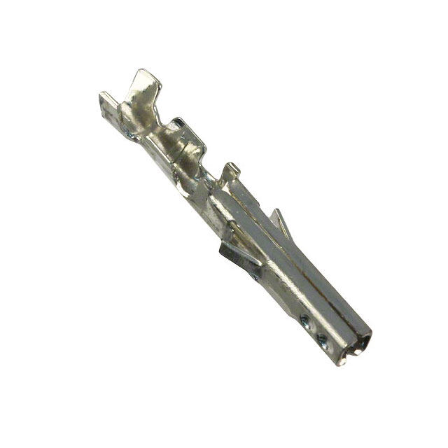
SBS® Silver Plated Primary Power Wire Contacts Use two silver plated contacts per housing for the best electrical performance and durability up to 10,000 mating cycles. Standard contacts are for use in all [ 7.6 ] primary power positions for SBS® 50, 75X, & 75G wire housings. See reducing 0.30 bushings in accessory section for smaller wires. See reducing busings in accessory section for smaller wires. [ 39.4 ] Dimensions 1.55 [ 12.4 ] 0.49 Loose Piece - A - Type AWG mm² ------ Part Numbers ------ inches mm Minimum Quantity .................. 1,000 100 ................... A Standard 6 16 1339G2-BK 1339G2* 0.22 5.59 [ 7.3 ] Standard 8 10 1339G5-BK 1339G5* 0.19 4.83 Ø 0.29 Standard 12 to 10 2.5 to 6 1339G3-BK 1339G3* 0.14 3.56 * Are sold as pairs. 2 contacts ship for every 1 ordered. SBS®75G Silver Plated Pre-Mate Wire Contacts Pre-Mate contacts are for the center Pre-Mate position on the SBS®75G wire Ground Indicator housings. See reducing bushings in accessory section for smaller wires. [ 7.6 ] Dimensions 0.30 Loose Piece - A - Type AWG mm² ------ Part Numbers ------ inches mm [ 41.9 + -1.5 ] Minimum Quantity .................. 500 50 ..................... 1.65 + - 0.06 [ 12.4 ] Pre-Mate 6 16 1340G1-BK 1340G1 0.22 5.59 0.49 Pre-Mate 8 10 1340G2-BK 1340G2 0.19 4.83 Pre-Mate 12 to 10 2.5 to 6 1340G3-BK 1340G3 0.14 3.56 A [ 7.3 ] Ø 0.29 SS BE P in Cont acts for SBS®75X Auxiliary SC G old plated c ontacts a re available in 3 le ngths to allow sequencing of circuits. 5®T DMeinsicmriupmtio Qn uantity ..............A..W....G... .........m...m...². ............. - - - - - - - -5--0-0-- ---- Part N u m b e r s 5 -0- - - - - -..-.-.-.-.-..-.-.-.- Retention Clip [Ø 1 0.6.006 ] 0 & 7ION Standard Length 7.7mm 12 2.5 PM16P12S30 PM16P12S30-50 ID 53 16 to 14 1.0 to 1.5 PM16P1416S30 PM16P1416S30-50 20 to 16 0.75 to 1.0 PM16P1620S30 PM16P1620S30-50 24 to 20 0.50 to 0.75 PM16P2024S30 PM16P2024S30-50 L1 Pre-Mate 9.3mm 12 2.5 PM16P12A30 - L 16 to 14 1.0 to 1.5 PM16P1416A30 - 20 to 16 0.75 to 1.0 PM16P1620A30 - 24 to 20 0.50 to 0.75 PM16P2024A30 - Auxiliary Pin - L - - L1 - Post-Mate 6.4mm 12 2.5 PM16P12C30 - Contact Lengths in. mm in. mm 16 to 14 1.0 to 1.5 PM16P1416C30 - Standard Length 7.7mm 0.77 19.6 0.30 7.7 20 to 16 0.75 to 1.0 PM16P1620C30 - Pre-Mate 9.3mm 0.83 21.2 0.37 9.3 24 to 20 0.50 to 0.75 PM16P2024C30 - Post-Mate 6.4mm 0.72 18.3 0.25 6.4 Socket Contacts for SBS®75X Auxiliary Selectively gold plated contacts offer low resistance and durability up to 10,000 mating cycles. [ 19.6 ] Description AWG mm² -------------------- Part Numbers ------------------- 0.77 Minimum Quantity .................................. 500 50 ............. Socket Contact 12 2.5 PM16S12S32 PM16S12S32-50 ID 16 to 14 1.0 to 1.5 PM16S1416S32 PM16S1416S32-50 [ 2.6 ] 20 to 16 0.75 to 1.0 PM16S1620S32 PM16S1620S32-50 Retention Socket 0.10 Clip Insert 24 to 20 0.50 to 0.75 PM16S2024S32 PM16S2024S32-50 Auxiliary Socket Contacts Crimp Barrel ID Wire Gauge in. mm. #24 / 20 0.04 1.1 #20 / 16 0.07 1.7 #16 / 14 0.08 2.1 #12 0.10 2.6 - 59 - All Data Subject To Change Without Notice www.andersonpower.com
| SBS® CONNECTOR SPECIFICATIONS | Electrical Mechanical Current Rating Amperes ¹ UL 1977 CSA/TUV Wire Size Range AWG mm² Primary Power (6 AWG) 110 75 Power Contacts (with bushings) 16 to 6 1.3 to 13.3 Auxiliary (12 AWG) 20 10 Auxiliary Contacts 24 to 12 0.25 to 3.3 Voltage Rating AC/DC Max. Wire Insulation Diameter in. mm UL 1977 600 SBS®75G Power & Ground 0.380 9.652 SBS®50 & SBS®75X Power Contacts 0.410 10.414 Dielectric Withstanding Voltage SBS®75X Auxiliary Contacts 0.140 3.600 Volts AC 2,200 Operating Temperature ² °F °C Avg. Mated Contact Resistance Milliohms ¹ Standard -4° to 221° -20° to 105° Power & Ground: 1 1/4” of #6 AWG wire 0.200 Chemical Resistant -40 to 221° -40° to 105° Auxiliary: Wire & PCB 3.000 Mating Cycles No Load by Plating Silver (Ag) Tin (Sn) Gold (Au) UL Hot Plug Current Rating Amperes - 250 cycles at 120V DC Power & Ground Contacts Wire 10,000 Wire & PCB Power 50A Power & Ground Contacts PCB 1,500 Wire & PCB Auxiliary 5A Auxiliary Contacts 10,000 UL Ground Short Time Current Test - SBS75G Wire & PCB Avg. Mating / Unmating Force Lbf. N 1530 Amps, #6 AWG Wire 6 seconds SBS®75X and SBS®75G Wire to Wire 16 70 SBS®50 Wire to Wire 8 36 SBS®75X and SBS®75G Wire to PCB 8 36 Materials Min. Contact / Spring Retention Force Lbf. N Power, Standard Housing 50 222 Housing Power, Chem. Resistant Housing 30 133 Standard Plastic Resin Polycarbonate Aux. Standard Housing 15 67 Chem. Resistant Resin Polycarbonate / PBT blend Aux. Chem. Resistant Housing 10 44 Contact Retention Spring Stainless Steel PCB Specifications Housing Flammability Rating Mounting Style Plated Through Hole UL94 V-0 Max PCB Thickness- in. [mm] 0.093 [2.4] Glow Wire - SBS50 825°C (GWFI) / 800°C (GWIT) Recommended Traces Power & Ground #6 AWG Cross Section - SBS75G 960°C (GWFI) / 800°C (GWIT) Recommended Traces Auxiliary #12 AWG Cross Section - SBS75X 960°C (GWFI) / 800°C (GWIT) Min. Creepage / Clearance Distance PCB in. mm Wire Power & Ground Contact Silver Plated Copper Alloy Power to Aux. Creepage SBS®75X 0.41 10.4 Power to Aux. Clearance SBS®75X 0.24 6.1 PCB Power & Ground Contact Tin Plated Copper Alloy Power to Ground Creepage SBS®75G 0.35 8.9 35 Power to Ground Clearance SBS®75G 0.26 6.7 7 N& SBS75X Auxiliary Contacts Auxiliary Creepage SBS®75X 0.12 3.0 O Pin Copper alloy, Au over Ni Auxiliary Clearance SBS®75X 0.12 3.0 TI50 Socket BeCu, Au over Ni C® Socket Body Copper alloy, Sn bright over Ni S Retention Clip Stainless Steel EB SS PCB Press Fit Retainers Brass - Tin Plated Contact Termination Methods Crimp ³ Wire Contacts Hand Solder Wire and PCB Contacts Solder Dip PCB Contacts Wave Solder PCB Contacts Auxiliary contacts are available for SBS®75X only. SBS®75X and SBS®75G PCB connectors are designed to mate only with the wire connector of the same series. NOTE 1: See IEC 60664-1 for working voltage. NOTE 2: Amp ratings are stated per position and based on all positions being fully loaded. ¹ Based on: 105°C rated or better cable of the largest size, Properly calibrated APP recommended tooling, and a 25°C ambient temperature. UL rating not to exceed the maximum operating temperature. CSA rating below a 30°C temperature rise. ² Limited by the thermal properties of the connector plastic housing. ³ Use APP recommended tooling only. Alternate tools may adversely affect the performance of our connectors along with UL and CSA recognition. - 60 - www.andersonpower.com All Data Subject To Change Without Notice
| IEC INFORMATION | Connector Creepage/Clearance Material Connector Creepage/Clearance Material Series Configurations per IEC 60950-1 Group Series Configurations per IEC 60950-1 Group Unmated 3.33 mm Unmated 3.33 mm SBS®75G IIIa SBS®75X IIIa Mated 4.64 mm Mated 4.64 mm Connector Creepage/Clearance Material Protection Series Configurations per IEC 60950-1 Group Touch Safety with Wire Contacts & PCB Mating Interface IEC 60950 Pass Unmated 3.85 mm SBS®50 IIIa IEC 60529 IP20 Mated 4.64 mm Attributes SBS50 AMP Rating AC/DC - Power only 6 AWGg-75a, 8 AWG 65A - 10 AWG - 45A, 12 AWG -35a Power Contacts and Aux contacts ( Aux contacts at 15 A) 6 AWGg-75a, 8 AWG 60A - 10 AWG - 35A, 12 AWG -30a - Aux Contacts 12 AWG - 15A Voltage Rating AC/DC (Steady State) 600 AC/DC (Operational) - Aux Contacts NA Breaking Capacity -AMP Rating /Cycles - Power Contacts 6 AWG -50 Amp, 120 VDC / 250 Cycles Breaking Capacity - Aux Contacts NA Voltage Rating (Breaking Capacity) 120 VDC Finger Safety - Mated only IEC 60529 - IP20 Wire Size tested Power 12, 10, 8, 6 AWG Contact Series Tested 1339G2, 1339G3, 1339G5 - Aux contacts NA SS Climatic Testing (Cold,Heat & MFG) IEC 60512 Test -11j, 11i & 11g, BE Cycle Life IEC 60512 Test 9a - 5000 Cycles SC ® Mechanical Strength Impact IEC 60512-5 @ 29.5 Inches - dropped 8 times 5T Temperature Range -20 °C to 105 °C 0IO & -4 °F to 221 °F N 7 53 Attributes SBS75x AMP Rating AC/DC - Power only 6 AWGg-75a, 8 AWG 65A - 10 AWG - 45A, 12 AWG -35a Power Contacts and Aux contacts ( Aux contacts at 15 A) 6 AWGg-75a, 8 AWG 60A - 10 AWG - 35A, 12 AWG -30a - Aux Contacts 12 AWG - 15A Voltage Rating AC/DC (Steady State) 600V AC/DC ( Operational) - Aux Contacts 12 AWG - 15A Breaking Capacity -AMP Rating /Cycles - Power Contacts 6 AWG- 50 Amp, 120 VDC / 250 Cycles Breaking Capacity - Aux Contacts 12 AWG -5A, 120 VDC / 250 Cycles Voltage Rating (Breaking Capacity) 120 VDC Finger Safety - Mated only IEC 60529 - IP20 Wire Size tested Power 12 AWG, 10 AWG , 8 AWG, 6AWG / signal 12 awg Contact Series Tested Power 1339G2, 1339G3, 1339G5 - Aux contacts PM16P12S30, PM16S12S32 Climatic Testing (Cold,Heat & MFG) IEC 60512 Test -11j, 11i & 11g, Cycle Life IEC 60512 Test 9a - 5000 Cycles Mechanical Strength Impact IEC 60512-5 @ 29.5 Inches - dropped 8 times Temperature Range -20 °C to 105 °C -4 °F to 221 °F NOTE 3: Refer to the Constructional Data form for additional information on our website., www.andersonpower.com - 61 - All Data Subject To Change Without Notice www.andersonpower.com
Attributes SBS75G AMP Rating AC/DC - Power only 110 Power Contacts and Aux contacts ( Aux contacts at 15 A) NA - Aux Contacts NA Voltage Rating AC/DC (Steady State) 600V AC/DC ( Operational) - Aux Contacts NA Breaking Capacity -AMP Rating /Cycles - Power Contacts 6 AWG- 50 A, 120 VDC / 250 Cycles Breaking Capacity - Aux Contacts NA Voltage Rating (Breaking Capacity) 120 VDC Finger Safety - Mated only IEC 60529 - IP10, IP20 Wire Size tested 6 AWG Contact Series Tested Power 1339G2, 1339G3, 1339G5 / Ground 1340G1 - Aux contacts NA Climatic Testing (Cold,Heat & MFG) IEC 60512 Test -11j, 11i & 11g, Cycle Life IEC 60512 Test 9a - 1500 Cycles Mechanical Strength Impact IEC 60512-5 @ 29.5 Inches - dropped 8 times Temperature Range -20 °C to 105 °C -4 °F to 221 °F Attributes SBS75G and GPR (PCB) AMP Rating AC/DC - Power only 110 Power Contacts and Aux contacts ( Aux contacts at 15 A) NA - Aux Contacts NA Voltage Rating AC/DC (Steady State) 600V AC/DC (Operational) - Aux Contacts NA Breaking Capacity -AMP Rating /Cycles - Power Contacts 6 AWG- 50 A,120 VDC / 250 Cycles Breaking Capacity - Aux Contacts NA Voltage Rating (Breaking Capacity) 120 VDC Finger Safety - Mated only IEC 60529 - IP20 Wire Size tested 6 AWG Contact Series Tested Power B02075P1 / Ground B02114P1 35 - Aux contacts NA N & 7 Climatic Testing (Cold,Heat & MFG) IEC 60512 Test -11j, 11i & 11g, O0 Cycle Life IEC 60512 Test 9a - 1500 Cycles TI5 Mechanical Strength Impact NA C® Temperature Range -20 °C to 105 °C S EB -4 °F to 221 °F SS NOTE 3: Refer to the Constructional Data form for additional information on our website., www.andersonpower.com - 62 - www.andersonpower.com All Data Subject To Change Without Notice
| SBS® CONNECTOR TEMPERATURE CHARTS | Temperature rise charts are based on a 25°C ambient temperature. For Temperature Rise Above 60°C, Consult the Extended Temperature Rise Charts in the Appropriate Product Section on the Website. Current - Temperature Derating per IEC 60512-5-2 Test 5B SBS®75x Primary Contacts Only SBS®75x Primary Contacts Only SBS®50 Temperature Rise at Constant Current Derating vs. Ambient Temperature Temperature Rise at Constant Current 60 125.0 60 50 C) 50 Temperature RiseAbove Ambient (°C)234000 bient Temperature (°1570050...000 Temperature RiseAbove Ambient (°C)234000 10 m 10 A 0 25.0 0 0 10 2030 40 50 60 70 80 90100110120 0 20 40 60 80 100 120 140 0 20 40 60 80 100 120 Amperes Applied Amperes Applied Amperes Applied 6 AWG 8 AWG 6 AWG 8 AWG 6 AWG 10 AWG 12 AWG 10 AWG 12 AWG 10 AWG 12 AWG SBS®75x Auxiliary Contacts @ 10A SBS®75x Auxiliary Contacts @ 10A SBS®50 Temperature Rise at Constant Current Derating vs. Ambient Temperature Derating vs. Ambient Temperature SS 60 125.0 125 BE SC 50 C) C) 5®T Temperature RiseAbove Ambient (°C)12340000 mbient Temperature (°1570050...000 mbient Temperature (°1570050 0 & 75ION 3 A A 0 0 10 20 30 40 50 60 70 80 90 100110 25.0 25 0 10 20 30 40 50 60 70 80 90100110 0 20 40 60 80 100 120 140 Amperes Applied Amperes Applied Amperes Applied 6 AWG 8 AWG 10 AWG 12 AWG 6 AWG 8 AWG 6 AWG 10 AWG 12 AWG 10 AWG 12 AWG SBS®75x Auxiliary Contacts @ 20A SBS®75x Auxiliary Contacts @ 20A Temperature Rise at Constant Current Derating vs. Ambient Temperature 60 125.0 50 C) Temperature RiseAbove Ambient (°C)12340000 mbient Temperature (°1570050...000 A 0 25.0 0 10 20 30 40 50 60 70 80 90 100110 0 10 20 30 40 50 60 70 80 90 100110 Amperes Applied Amperes Applied 6 AWG 8 AWG 6 AWG 8 AWG 10 AWG 12 AWG 10 AWG 12 AWG - 63 - All Data Subject To Change Without Notice www.andersonpower.com
For Temperature Rise Above 60°C, Consult the Extended Temperature Rise Charts in the Appropriate Product Section on the Website. SBS®75G Primary Contacts Only SBS®75G All Contacts Powered SBS®75GPR All Contacts Powered No Power Center Contact Temperature Rise at Constant Current Temperature Rise at Constant Current Temperature Rise at Constant Current 60 60 60 50 50 50 Temperature RiseAbove Ambient (°C)234000 Temperature RiseAbove Ambient (°C)234000 Temperature RiseAbove Ambient (°C)234000 10 10 10 0 0 0 0 20 40 60 80 100 120 0 10 20 30 40 50 60 70 80 90 100 0 10 2030 40 50 60 70 80 90100110120 Amperes Applied Amperes Applied Amperes Applied 6 AWG 8 AWG 6 AWG 8 AWG 6 AWG 8 AWG 10 AWG 12 AWG 10 AWG 12 AWG 10 AWG 12 AWG Current - Temperature Derating per IEC 60512-5-2 Test 5B SBS®75G Primary Contacts Only SBS®75G All Contacts Powered SBS®75GPR All Contacts Powered No Power Center Contact Derating vs. Ambient Temperature Derating vs. Ambient Temperature Derating vs. Ambient Temperature 125 125 125 C) C) C) e (°100 e (°100 e (°100 ur ur ur at at at er er er mp 75 mp 75 mp75 e e e T T T nt nt nt e e e mbi 50 mbi 50 mbi50 A A A 25 25 25 35 0 20 40 60 80 100 120 140 0 20 40 60 80 100 120 0 20 40 60 80 100 120 140 7 N& Amperes Applied Amperes Applied Amperes Applied O0 6 AWG 8 AWG 6 AWG 8 AWG 6 AWG 8 AWG TI5 10 AWG 12 AWG 10 AWG 12 AWG 10 AWG 12 AWG C® S EB SS | SBS® ACCESSORIES | Mounting Clamp for SBS®50 [ 20.8 ] [ 20.8 ] [ 20.8 ] Mounting clamps can be used for fastening a SBS®50 series 0.82 0.82 0.82 [ 4.6 ] [ 1.5 ] housings to a panel. Fastening hardware not included. Ø 0.18 TYP 0.06 [ 26.4 ] 1.04 Description --- Part Number --- Minimum Quantity .......................... 20 sets of 2 ..... [ 25.1 ] [ 33.5 ] Panel Mount Bracket for SBS®50 1466G1 0.99 1.32 [ 28.2 ] 1.11 [ 50.0 ] 1.97 T-Handle for SBS®50 and SBS®75X The “T” handle makes mating and unmating the connector easier. The non-conductive red plastic material is strong and safe. (2) Self tapping screws are used to secure the handle to the connector housing. Description ---------- Part Numbers ---------- Minimum Quantity ............................... 1,000 50 .......... Red “T” Handle + Hardware Bag - SBS50-HDL-RED Hardware Bag (2 Screws) - 104G17 Red “T” Handle Only 113899P1 - #8 x 5/8” Screw (Order 2 Per Handle) H1120P55 - - 64 - www.andersonpower.com All Data Subject To Change Without Notice
“A” frame handle for SBS®50 and SBS®75X Handle makes mating and unmating the connector easier. The non-conductive gray plastic material is strong and safe. Machine screws and locknuts included. Screws Description - Part Number - Minimum Quantity ..................... 200 ....... Handle Connector Housing Gray “A” Handle & Hardware 997G1 Locknuts T-Handle for SBS®75G The “T” handle makes mating and unmating the connector easier. The non-conductive red plastic material is strong and safe. (2) Machine screws and lock nuts. Description - Part Number - Minimum Quantity .............................. 50 .... Red “T” Handle + Hardware Bag SBS75GHDLRED Dust Cover SBS®50 Prevents dust and dirt from entering the mating interface of the connector when unmated. NOTE: Not a Hermetic Seal. Shown with the SB®50 Description ---- Part Number ---- Minimum Quantity ............................. 500 50 ... Dust Cover with Lanyard Strap, Red 113890P1 134G1 Slide cover over mating end. SS BE Cable Clamps for SBS®50 S®C Durable metal cable clamps securely hold cables to prevent accidental strain or pulls from dislodging 50TIO wire or contacts from the housing. Cable clamps are recommended for solder terminated wires. & N Cable Size 5905 7 AWG or mm² or 53 Description (Inches O.D.) (mm O.D.) ----- Part Numbers ----- Minimum Quantity ......................................................................................... 500 50 ... Self Attaching for Discrete Conductor 8 to 6 10 990-BK 990 Shown with the SB®50 Self Attaching for Discrete Conductor 12 to 10 2.5 to 4 990G2-BK 990G2 Bolt on bundled Bolt On for Discrete Conductor 12 to 6 2.5 to 10 990G1-BK 990G1 conductors. Bolt On for Bundled Conductor (0.320 to 0.450) (4.27 to 11.43) 5905-BK 5905 990 The given wire O.D. information is an estimate. Cable clamps should be evaluated for performance with the actual wire to be used. Self attaching discrete conductor. Cable Clamps for SBS®75X with Integral Handle Rugged chemical resistant PBT/ PC plastic cable clamps securely hold cables to prevent accidental strain or pulls from dislodging wire or contacts from the housing. Cable clamps are recommended for solder terminated wires. Cable Size AWG or mm² or Description (Inches O.D.) (mm O.D.) ------------------ Part Numbers ------------------- Minimum Quantity ..................................................................................................... 100 25 ....... Large Wire Clamp Kit w/ Hardware 12 to 6 (0.39 to 0.60) 4 to 10 (9.9 to 15.2) PSBS75XCLP1-BK PSBS75XCLP1 Small Wire Clamp Kit w/ Hardware 12 to 6 (0.34 to 0.55) 4 to 10 (8.6 to 14.0) PSBS75XCLP2-BK PSBS75XCLP2 [ 21.8 ] [ 36.4 ] 0.86 1.44 The given wire O.D. information is an estimate. Cable clamps should [ 48.3 ] [ 55.5 ] [ 45.9 ] be evaluated for performance with 1.90 2.18 1.81 the actual wire to be used. Clamp hardware requires phillips or flat blade screwdriver to assemble. - 65 - All Data Subject To Change Without Notice www.andersonpower.com
Reducing Bushings Use with contact part number 1339G2-BK or 1340G1-BK to allow a smaller wire to be used with the connector. Electrical capability is derated with smaller wire. Dimensions - ID - - Length - Contact Barrel Size Wire Size -------- Part Numbers -------- inches mm inches mm Minimum Quantity ...................................................... 3,000 1,000 100 ..................................................... Length ID #6 AWG [13.3 mm²] #8 AWG [8.4 mm²] - 5912-BK 5912 0.18 4.57 0.45 11.43 #6 AWG [13.3 mm²] #12- 10 AWG [3.3- 5.3 mm²] 5910-BK - 5910 0.14 3.56 0.47 11.94 #6 AWG [13.3 mm²] #16- 14 AWG [1.3- 2.1 mm²] 5913-BK - 5913 0.09 2.29 0.47 11.94 Wire Entrance SBS® - Tooling Information Wire Size Power / Ground Contacts Power Contact Pneumatic Bench Number of AWG mm² Part Number Tool Die Locator Crimps Hand Tool #6 13.3 1339G2 1388G6 #8 8.4 1339G5 1389G9 #10 / 12 5.3 / 3.3 1339G3 1388G7 1387G1 Single 1309G4 #6 13.3 1340G1 1388G6 #8 8.4 1340G2 1389G20 #10 / 12 5.3 / 3.3 1340G3 1388G7 Wire Size SBS®75X Auxiliary Contacts Mil Std. Hand Locator for: 35 Auxiliary Contact APP Hand Tool w/ Tool* Pneumatic Number TM0001 & N & 7 AWG mm² Part Number Integral Locator M22520/1-01 Tool* of Crimps TP0001 O TI50 All Crimp Pins TL0001 C® #12 / 24 2.5 / 0.25 PM1000G1 TM0001 TP0001 Single S EB All Crimp Sockets TL0002 SS * TP0001 and TM0001 tools require locators TL0001 for Pins and TL0002 for Sockets. NOTE: See website for the most current information. SBS®75X Auxiliary Contact Insertion Tool: PM1002G1 SBS®75X Auxiliary Contact Extraction Tool: PM1003G1 SBS®75X Auxiliary Contact Insertion Inspection Tool: PM1003GX The auxiliary contacts used with wire sizes #16 - #24 AWG cannot be properly inserted without the insertion tool. Properly installed auxiliary contact of al wire gauges cannot be removed from the hosing without the extraction tool. - 66 - www.andersonpower.com 2018-0054 DS-SBS REV C6 All Data Subject To Change Without Notice
Mouser Electronics Authorized Distributor Click to View Pricing, Inventory, Delivery & Lifecycle Information: A nderson Power Products: 1339G4 5910 5913 1339g1 1466G1 5905 6331G11 6331G12 6331G7 PSBS50GRA SBS50BLK SBS50BLK#10/12 SBS50BLK#6 sbs50blk-bk SBS50BLU SBS50BLU#10/12 SBS50BLU#6 SBS50BLU-BK SBS50BRN SBS50BRN#10/12 SBS50BRN#6 SBS50BRN-BK SBS50GRA SBS50GRA#6 SBS50GRA-BK SBS50- HDL-RED SBS50RED SBS50RED#10/12 sbs50red#6 SBS50RED-BK SBS50WHT SBS50WHT#10/12 SBS50WHT#6 SBS50WHT-BK SBS75XBLK SBS75XBLK-BK SBS75XPRBLK SBS75XPRBLK-BK 1388G7 SBS75xCLP2 PSBS75XCLP2 PSBS75XCLP1-BK PSBS75XCLP2-BK PM16P1416C30 PM16P2024C30 PM16P1620S30-50 PM16S1620S32-50 PSBS75XBLK SBS75XCLP1 1340G3 1340G1-BK SBS75GBLK-BK 1340G3-BK SBS75GBLU-BK SBS75GBRN-BK 1340G2 1340g1 SBS75GWHT-BK SBS75XBRN-BK SBS75GPRBLK-BK SBS75GBLK SBS75XBRN 1340G2-BK PSBS50BLU PSBS75XGRN-BK PSBS50GRN SBO60ORN-BK E6334G2 PSBS75XCLP1 6337G1 PSBS50GRA-BK PSBS50GRN-BK PSBS50BLK-BK PSBS50RED-BK PSBS50BLU-BK PSBS75XBLK-BK PSBS50BRN-BK SBS75XCLP2-BK SBS75XGRN-BK SBS75XCLP1-BK SBS75GBLU SBS75GBRN PSBS50BLK SBS75XGRN SBS75GWHT 997G1