ICGOO在线商城 > 连接器,互连器件 > 端子 - 磁线连接器 > 63218-1

 Datasheet下载
- 型号: 63218-1
- 制造商: CORCOM/TYCO ELECTRONICS
- 库位|库存: xxxx|xxxx
- 要求:
| 数量阶梯 | 香港交货 | 国内含税 |
| +xxxx | $xxxx | ¥xxxx |
查看当月历史价格
查看今年历史价格
63218-1产品简介:
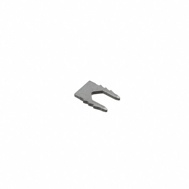
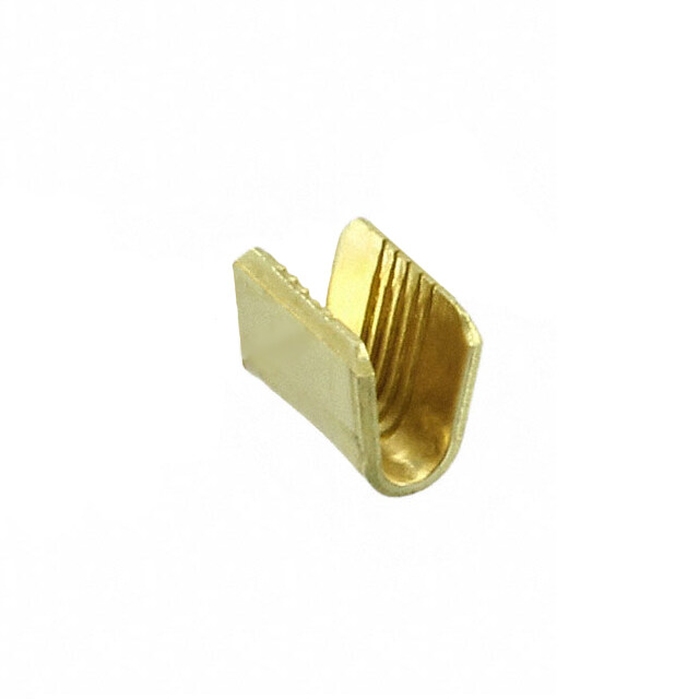
ICGOO电子元器件商城为您提供63218-1由CORCOM/TYCO ELECTRONICS设计生产,在icgoo商城现货销售,并且可以通过原厂、代理商等渠道进行代购。 63218-1价格参考¥0.34-¥0.46。CORCOM/TYCO ELECTRONICS63218-1封装/规格:端子 - 磁线连接器, Terminal Magnetic Connector 14-18 AWG IDC。您可以下载63218-1参考资料、Datasheet数据手册功能说明书,资料中有63218-1 详细功能的应用电路图电压和使用方法及教程。
TE Connectivity AMP Connectors 的型号为63218-1的端子 - 磁线连接器主要应用于需要安全、可靠电气连接的场景。这种连接器广泛用于汽车、工业设备和家电等领域,特别是在涉及高电流或高频信号传输的地方。

在汽车行业,63218-1连接器常用于发动机控制单元(ECU)、传感器接口、照明系统和其他关键电子组件中。它确保了这些部件之间的稳定通信和电力供应,从而提高了车辆的整体性能和安全性。例如,在电动汽车中,该连接器可以用于电池管理系统与电机控制器之间的连接,保证高效且稳定的能量传递。

在工业领域,此款连接器适用于各种自动化设备和控制系统,如机器人手臂、PLC(可编程逻辑控制器)以及变频驱动装置等。由于其良好的抗震性和耐久性,即使在恶劣的工作环境下也能保持长期可靠的运行状态。

对于家用电器而言,63218-1连接器同样发挥着重要作用。它可以出现在冰箱、洗衣机、空调等大型家电内部,负责将电源分配给不同的功能模块,并支持数据交换以实现智能化操作。此外,它还可能被用作智能插座或其他智能家居产品的接口,便于用户进行远程控制和监控。

总之,TE Connectivity AMP Connectors 的63218-1端子 - 磁线连接器凭借其卓越的设计和出色的性能,在众多行业中都得到了广泛应用,成为现代电子产品不可或缺的一部分。
| 参数 | 数值 |
| 产品目录 | |
| 描述 | TERMINAL MAG-MATE |
| 产品分类 | |
| 品牌 | TE Connectivity |
| 数据手册 | http://www.te.com/commerce/DocumentDelivery/DDEController?Action=srchrtrv&DocNm=63218&DocType=Customer+Drawing&DocLang=English |
| 产品图片 | |
| 产品型号 | 63218-1 |
| rohs | 不适用 / 符合限制有害物质指令(RoHS)规范要求 |
| 产品系列 | Mag-Mate,AMP |
| 其它名称 | 632181 |
| 包装 | 剪切带 (CT) |
| 尺寸 | - |
| 标准包装 | 1 |
| 样式 | - |
| 特性 | 90° 下 |
| 端子类型 | 插入式接片端子 |
| 端接 | IDC |
| 线规 | 14-18 AWG |


- 商务部:美国ITC正式对集成电路等产品启动337调查
- 曝三星4nm工艺存在良率问题 高通将骁龙8 Gen1或转产台积电
- 太阳诱电将投资9.5亿元在常州建新厂生产MLCC 预计2023年完工
- 英特尔发布欧洲新工厂建设计划 深化IDM 2.0 战略
- 台积电先进制程称霸业界 有大客户加持明年业绩稳了
- 达到5530亿美元!SIA预计今年全球半导体销售额将创下新高
- 英特尔拟将自动驾驶子公司Mobileye上市 估值或超500亿美元
- 三星加码芯片和SET,合并消费电子和移动部门,撤换高东真等 CEO
- 三星电子宣布重大人事变动 还合并消费电子和移动部门
- 海关总署:前11个月进口集成电路产品价值2.52万亿元 增长14.8%


PDF Datasheet 数据手册内容提取
MAGNET WIRE TERMINALS AND TERMINATION SYSTEMS MAG-MATE terminals, SIAMEZE terminals, AMPLIVAR terminals and splices, and cluster blocks APPLIANCES /// MAGNET WIRE TERMINATION
Magnet Wire Terminals and Termination Systems Catalog 82221 Table of Contents Standard MAG-MATE Terminals Introduction.....................................................................................................................................1 Interconnection System..................................................................................................................2 Termination Sequence ...................................................................................................................2 Test Results ....................................................................................................................................3 300 Box Poke-In Terminals ............................................................................................................4 500 Box Poke-In Terminals ............................................................................................................6 Poke-In Tab Terminals ...................................................................................................................7 MAG-MATE Terminals with extended leaf-spring ..........................................................................8 300 Box Poke-In Terminals ............................................................................................................9 Tab Receptacle Terminals ..............................................................................................................9 187 Box F-Crimp Terminals ..........................................................................................................10 300 Box F-Crimp Terminals ..........................................................................................................10 Posted PCB Terminals .................................................................................................................11 300 Box Posted PCB Terminals ...................................................................................................11 MAG-MATE Edge Leaf Terminals ................................................................................................12 187 Box Posted PCB Terminals ...................................................................................................13 187 Box Tab Terminals ................................................................................................................13 300 Box Tab Terminals ................................................................................................................14 Pin Receptacle Terminals .............................................................................................................15 Pin I/O Terminals ..........................................................................................................................16 110 Series FASTON Tab Terminals ..............................................................................................17 187 Series FASTON Tab Terminals ..............................................................................................18 187 Series Combination Poke-In FASTON Terminals .................................................................18 250 Series FASTON Tab Terminals ..............................................................................................21 Typical Plastic Cavity ....................................................................................................................23 Slim Line MAG-MATE Terminals Introduction...................................................................................................................................25 187 Series FASTON Tab Terminals ..............................................................................................26 250 Series FASTON Tab Terminals ..............................................................................................26 Posted PCB SOLDER Terminal ...................................................................................................26 Offset Tab Terminals.....................................................................................................................27 Mini MAG-MATE Terminals Introduction...................................................................................................................................29 Poke-In Terminal ..........................................................................................................................30 Posted Terminal ...........................................................................................................................31 FASTON Tab Terminals ................................................................................................................31 Crimp Wire Barrel Terminal ..........................................................................................................31 SIAMEZE Terminals Introduction...................................................................................................................................32 Lead Lok Terminals Introduction ..................................................................................................33 SIAMEZE Interconnection System...............................................................................................34 Lead Lok Interconnection System................................................................................................35 Wire-to-Wire Terminals .................................................................................................................36 Receptacle Terminals (Wire to Blade) .........................................................................................37 Pin Terminals ................................................................................................................................37 Post Terminals ..............................................................................................................................38 110 Series (2.8 mm wide) FASTON Tab Terminals ......................................................................39 187 Series (4.75 mm wide) FASTON Tab Terminals ....................................................................40 250 Series (6.3 mm wide) FASTON Tab Terminals ......................................................................41 Typical Plastic Cavity Pockets ......................................................................................................42 Dimensions are in inches and Dimensions are shown for www.te.com/appliances millimeters unless otherwise reference purposes only. specified. Values in brackets Specifications subject to change. are metric equivalents.
Magnet Wire Terminals and Termination Systems Catalog 82221 Table of Contents AMPLIVAR Splices Introduction...................................................................................................................................44 General Application Guidelines ....................................................................................................46 Suggested Splice Selection Procedure .......................................................................................46 Technical Documents ...................................................................................................................46 9 Serrations —Pigtail Type ...........................................................................................................47 7 Serrations —Pigtail Type ...........................................................................................................47 5 Serrations —Thru Type .............................................................................................................48 5 Serrations —Pigtail Type ...........................................................................................................49 Miniature Splice —Pigtail Type ....................................................................................................49 AMPLIVAR Terminals Introduction...................................................................................................................................50 Ring Tongue Terminals ................................................................................................................51 Stud Retaining Terminals .............................................................................................................52 Alternator Eyelet Terminal ............................................................................................................52 125 Series Blade..........................................................................................................................53 187 Series FASTON Tabs ..........................................................................................................53 250 Series FASTON Tabs ..........................................................................................................53 250 Series FASTON Receptacles ..............................................................................................64 187 Series FASTON Flag Receptacles .......................................................................................55 250 Series FASTON Flag Receptacles ........................................................................................55 Pin Receptacles............................................................................................................................55 250 Series Stator Receptacles —7 Serrations ............................................................................56 Stator Terminal —Receptacle .250 x .032 [6.35 x 0.81] ..............................................................56 Cluster Blocks Introduction...................................................................................................................................57 Cluster Blocks 2.29 [.090] Pin Size (Lead Wire and Direct Connect)...........................................58 Cluster Blocks 3.18 [.125] Pin Size (Lead Wire and Direct Connect)...........................................60 MTM Crimpband Splices - NOT RECOMMENDED FOR NEW DESIGNS Introduction...................................................................................................................................62 MTM Crimpband Interconnection System....................................................................................63 11 Serrations ................................................................................................................................64 9 Serrations..................................................................................................................................64 7 Serrations..................................................................................................................................65 RTM Crimpband Splices - NOT RECOMMENDED FOR NEW DESIGNS Introduction...................................................................................................................................66 RTM Crimpband Interconnection System .....................................................................................67 20 Ridges.....................................................................................................................................68 14 Ridges.....................................................................................................................................68 10 Ridges.....................................................................................................................................68 9 Ridges.......................................................................................................................................69 8 Ridges.......................................................................................................................................69 7 Ridges.......................................................................................................................................69 6 Ridges.......................................................................................................................................72 3 Ridges.......................................................................................................................................73 Power Splice Introduction...................................................................................................................................74 Dimensions are in inches and Dimensions are shown for www.te.com/appliances millimeters unless otherwise reference purposes only. specified. Values in brackets Specifications subject to change. are metric equivalents.
Magnet Wire Terminals and Termination Systems Catalog 82221 Table of Contents Application Tooling Introduction...................................................................................................................................76 AMPLIVAR Product Terminator (APT)Machine ............................................................................77 Power Splice Machine ..................................................................................................................77 AMPLIVAR Terminator for Parallel and End Connections ............................................................78 AMP-O-LECTRIC Model G Terminator with Thru-Splice Applicator .............................................78 Crimpband Application Tooling - NO LONGER AVAILABLE.......................................................... 79 MPT-5 MAG-MATE Product Terminator .......................................................................................80 MAG-MATE Terminal Cavity and Fixture Design ..........................................................................80 MPT-5 S/L Machine for SIAMEZE and Lead Lok Terminals .........................................................81 EMT -- Entry Level Magnet Wire Terminator ................................................................................81 Manual Hand Tool .........................................................................................................................82 Manual Arbor Press ......................................................................................................................82 Hand Insertion Tools .....................................................................................................................82 Full Line of Crimp Tooling .............................................................................................................82 MAG-MATE Inserter MK I with Pneumatic Control .......................................................................83 MAG-MATE Inserter MK I with Electro Pneumatic Control ...........................................................83 MAG-MATE and SIAMEZE Inserter MARK II with PLC ................................................................83 MAG-MATE and SIAMEZE Inserter MARK II with PLC and Insertion Force Control ...................84 Pneumatic Insertion Tool for MAG-MATE Terminals....................................................................84 Customer Specific Machines ........................................................................................................85 Custom Built IDC Terminal Insertion Head ...................................................................................85 Additional Data Technical Information ...................................................................................................................86 Terminal Stud Hole Size ...............................................................................................................90 Part Number Index .......................................................................................................................91 Dimensions are in inches and Dimensions are shown for www.te.com/appliances millimeters unless otherwise reference purposes only. specified. Values in brackets Specifications subject to change. are metric equivalents.
Magnet Wire Terminals and Termination Systems Catalog 82221 Standard MAG-MATE Terminals Product Facts Terminates film-insulated copperand aluminum TS magnetwire ermtan Eliminates need for inda ar pre-stripping conductors lsd M Eliminates need to post AG insulate termination -M A Excess magnetwire is T E automatically trimmed during the termination process Simultaneously terminates two magnetwires ofthe same size in one terminal (forsplicing orbi-filing) Various lead wire attachmentoptions available Available in strip form for semi-automaticorfully automaticinsertions Available in loose piece form forhand toolinsertions Varnish resisttabterminals are available forspecial applications TEoffersafullselectionof Twomagnetwireswiththe Wipingactionbetween High speed,fully automated StandardMAG-MATE samediametercanbe thewireandterminal integratedsystems provide InsulationDisplacement terminatedinoneterminal removesoxidesorother uniform terminations Crimp(IDC)terminalsfor exceptasnoted. contaminantspresenton reliably atthelowest magnetwireterminations. boththeconductorandthe possible applied cost AccordingtoTE terminalslotsidewalls, MAG-MATEterminalsare specifications MAG-MATE Clean metal-to-metal producingaclean,stable, availableinpoke-in, cavitiesareeither interface produces stable, gas-tightelectrical poke-intab,splice,crimp integratedintocoilbodies gas-tightelectrical termination. wirebarrel,solderpost, orspeciallydesignedcavity terminations free ofoxides quickconnecttab,pinand housings.Themagnet Residualspringenergyin and othercontaminants receptaclestyles. wiresareprecisely theterminalcausesthe Recognized underthe positionedintheplastic sidewallsofeachIDCslot StandardMAG-MATE ComponentRecognition cavityslots. tofunctionasopposing terminatesmagnetwire Program ofUnderwriters cantileverbeams. rangingfrom34-12AWG TheMAG-MATEInserter Laboratories Inc.,File No. [0.16-2.05mm]. cutstheterminalsfromthe Thisconstantpressure E13288,Vol. 1,Sec29 stripandplacesthe resultsinanintimate EachIDCslotsize terminalsoverthemagnet metal-to-metalinterface, terminatesarangeofupto R wireintotheplastic providingareliable, fourconsecutivemagnet cavities. long-termconnection. Applications wiresizes. Duringthisoperation,small The MAG-MATE Motor windings and strippingshouldersinthe Insertermaybeusedasa connections IDCslotremovethefilm semi-automaticbench Coil connections insulationfromthemagnet machineorintegratedinto wire. productionlinesfor Transformer windings fully-automaticapplications. and connections Bobbin connections Lighting ballasts Power supplies *Contact TE Engineering for guidance regarding aluminum 1 www.te.com/appliances
Magnet Wire Terminals and Termination Systems Catalog 82221 Standard MAG-MATE Terminals (Continued) Standard MAG-MATE Interconnection System How the System Operates Trim Blade Locking Barbs This part cuts off the excess Terminal retention is secured magnet wire and the wire in the cavity by four locking support at the front of the barbs. cavity. Plastic Cavity Insertion Finger Integration of plastic cavities into final unit must be in The insertion finger is part of accordance with TE the MAG-MATE Inserter. It Application Specifications. pushes the terminal that was Consulting TE sheared from the carrier strip through the inserter is required for design in. “tube” into the positioned Cavity Slot for Wire cavity. The width has to be in Contact accordance with the wire Various wire attachments in size(see Application Specifi- three different sizes,.187, cation). .300,.500 cavity height (see Magnet Wire tables). The magnet wire is IDC Slot positioned down into the In different sizes for magnet plastic cavity slots. wire diameters from 34-12 Wire Support Block AWG[0.16-2.05 mm]. Strain relief slots available for high The block supports the vibration applications. magnet wire during the cutting process. The magnet Stripping Shoulders wire is cut flush to the cavity During the insertion process, front side. these shoulders strip the film 11 Support Anvil insulation from the magnet wire in four areas. The anvil supports the wire during the insertion process. Termination Sequence 11 A = Prepare B = Insert C = Finish A B C Trim Blade Insertion Finger Poke-In Contact Plastic Cavity Magnet Wire Support Anvil 2 www.te.com/appliances
Magnet Wire Terminals and Termination Systems Catalog 82221 Standard MAG-MATE Terminals (Continued) Test Results Current Cycling— Humidity— Mini MAG-MATE Standard and Slim Line 480 cycles with each cycle Temperature Cycling products have been submitted to MAG-MATE products have consisting of 15 minutes “ON” 10 cycles between 25°C and the following tests in addition to TS btineecsertesn a wssuietbh:mouittt esdig ntoif itchaen fto mlloilwlivinoglt fT2o5hll ocewyrcmeldea sbl wyS i1thh5o emcaikcnh—u tceysc l“eO FF” 6H353e° daCat yaAst g9a5et %1—1 R8°HC tmVhiiolblsivreoa lltitsi iotnencdr— ewaistheo:ut significant erminatandar cfoolnloswisetidn gb yo f3 300 m mininuutetes sa at t- 6152°5C°C 1m0in-5u5te-0 a1t- .H06z itnracvheerss etodt ainl 1 lsd M A excursion; 2 hours in each of 3 G mutually perpendicular -M directions. A T Industrial Gas with E 3” Chlorine— I1 [7.62 mm ] I2 Current Leads 1000 exposure to 200 ppb each of sulphur dioxide, nitrogen E1 E2 Voltage dioxide, hydrogen sulphide and 50 ppb chlorine. Resistance vs Thermal Shock (Copper Wire) Resistance vs Current Cycles (Copper Wire) 35 30 25 s m ms 20 oh Millioh 15 Milli 10 5 0 0 5 10 15 20 25 Test Current produces 100°C Magnet Wire Operating Temperature Product Specifications GG GG G G G G G T(C) WW WW W W W W W describe technical performance AA AA A A A A A 3 0 7 6 4 2 9 6 5 characteristics and verification 33 22 2 2 1 1 1 tests. They are intended for the Design, Test and Quality Engineer. 108-2012 Standard .187 and .300 MAG-MATE Terminals 108-2053 Standard .500 Box Current Rating Curves MAG-MATE The diagram shows the Terminals temperature rise of the 108-1484 Slim Line MAG-MATE contact, depending on the Terminals magnet wire size being 108-2016 Mini MAG-MATE applied. Terminals Note:For all applications, TE I (A) recommends that samples of the magnet wire to be used be submitted for engineering evaluation. 3 www.te.com/appliances
Magnet Wire Terminals and Termination Systems Catalog 82221 Standard MAG-MATE Terminals (Continued) 300 BoxPoke-In Terminals Materrial Tinplatedbrass Type Copper Magnet Wire Range1 Lead Wire Range3 Mating5 Stock Strip AWG mm AWG mm2 Tab ThicknessPart Number* .135 x .020 .010 34-33 0.16-0.18 20-18 0.5-0.9 63662-1 3.40 x 0.50 0.25 TypicalCavitySize2 .135 x .020 .010 (Seepage23) 33-31 0.18-0.23 20-18 0.5-0.9 3.40 x 0.50 0.25 62431-1 .135 x .020 .012 31-28 0.23-0.32 20-18 0.5-0.9 1217234-1 3.40 x 0.50 0.30 .135 x .020 .012 30-27 0.25-0.36 20-18 0.5-0.9 62429-1 3.40 x 0.50 0.30 A [ .73.0602 ] Sta3n0d0a Brdo IxDC 27-23 0.36-0.57 20-18 0.5-0.9 .31.3450 xx .00.2500 .00.1461 62935-1 [ .31.3453 ] LPoockkei-ning 25-222 0.45-0.64 20-18 0.5-0.9 .31.3450 xx .00.2500 .00.1461 63658-1 [ .31.1080 ] 22-202 0.64-0.81 20-18 0.5-0.9 .31.3450 xx .00.2500 .00.1461 62420-1 202 0.81 20-18 0.5-0.9 .135 x .020 .016 63591-1 A 3.40 x 0.50 0.41 19-172 0.91-1.15 20-18 0.5-0.9 .135 x .020 .016 62833-1 3.40 x 0.50 0.41 .135 x .020 .012 30 0.25 20-18 0.5-0.9 63786-1 B4 3.40 x 0.50 0.30 300 Box 29-28 0.29-0.32 20-18 0.5-0.9 .135 x .020 .012 1217011-1 .300 Standard IDC w/ 3.40 x 0.50 0.30 [ 7.62 ] StraiLno Rcekilniegf Slot 28-26 0.32-0.40 20-18 0.5-0.9 .31.3450 xx .00.2500 .00.1320 1217368-1 .135 Poke-In [ 3.43 ] .135 x .020 .016 27-23 0.36-0.57 20-18 0.5-0.9 63789-1 .118 3.40 x 0.50 0.41 [ 3.00 ] 1Twomagnetwiresmaybeterminatedinthesameterminalslotifdiametersareequal. 2Singlemagnetwireonly;22AWG[0.64mm]orlargerunlessotherwisenoted. B 3Solidorovercoatedstrandedleadwireonly.ProductwillalsoacceptPoke-InTabTerminalshownonpage 7. 4Strainreliefslotforhighvibrationapplications. 5Seepage7 for mating tab options. * RecognizedundertheComponentProgramofUnderwritersLaboratories,Inc. Solid Lead Wire Solid SOLID WIRE Lead Wire MAGMATE POKE-IN MAGMATE Terminal SOLID WIRE LOCKS Terminal IN “V” NOTCH Cavity Magnet Wire Cavity POKE-IN SYSTEM: SOLID WIRE CONNECTION Stranded Lead Wire Stranded Lead Wire POKE-IN TAB POKE-IN TAB Terminal MAGMATE POKE-IN TAB Terminal Locking Terminal Grooves Tab locks into POKE-IN MAGMATE edges of leaf Terminal Magnet Wire Cavity Cavity POKE-IN SYSTEM: STRANDED LEAD WIRE AND POKE-IN TAB CONNECTION 4 www.te.com/appliances
Magnet Wire Terminals and Termination Systems Catalog 82221 Standard MAG-MATE Terminals (Continued) TS erta mn inda ar lsd M .300 [ 7.62 ] Type Copper Magnet Wire Range1 Mating Tab3 Stock Strip AG .135 AWG mm Thickness Part Number* - [ 3.43 ] .118 35-32 0.14-0.20 .31.3450 xx .00.2500 .00.1205 969082-1 MAT [ 3.00 ] E 33-30 0.18-0.265 .31.3450 xx .00.2500 .00.1205 926850-2 A Sta3n0d0aA Brdo IxDC 30-26 0.265-0.40 .31.3450 xx .00.2500 .00.1332 926851-2 NPoonke-L-Ionc kMinKgI 26-21.52 0.40-0.67 .31.3450 xx .00.2500 .00.1461 926852-2 21.5-18.52 0.67-0.95 .31.3450 xx .00.2500 .00.1461 928770-2 [ .73.0602 ] 19.5-172 0.91-1.13 .31.3450 xx .00.2500 .00.1461 1-928771-4 .135 x .020 .013 33-30 0.18-0.265 964337-2 3.40 x 0.50 0.32 .135 [ 3.43 ] .118 B 30-26 0.265-0.40 .135 x .020 .013 964338-2 [ 3.00 ] 300 Box 3.40 x 0.50 0.32 Standard IDC 26-222 0.40-0.63 .135 x .020 .013 964339-2 Non-Locking 3.40 x 0.50 0.32 B Poke-In MKII 22-19.52 0.63-0.85 .135 x .020 .013 964340-2 3.40 x 0.50 0.32 19.5-172 0.85-1.12 .135 x .020 .013 964341-2 3.40 x 0.50 0.32 Type Copper Magnet Wire Range1 Feature Stock Strip AWG mm Thickness Part Number .433 C 33-30 0.18-0.265 w/o Dimple .013 1-964114-1 [ 11.00 ] 433 Box Dimple 0.32 964114-1 Standard IDC w/o Dimple .013 1-964108-1 with Receptacle 30-26 0.265-0.40 Dimple 0.32 964108-1 for Tabs w/o Dimple .013 1-928854-1 .110 x .020 26-22 0.40-0.63 .135 .125 [2.8 mm x 0.5 mm] Dimple 0.32 928854-1 [ 3.43 ] [ 3.20 ] or .110 x .032 22-19.52 0.63-0.85 w/o Dimple .013 1-964106-1 [2.8 mm x 0.8 mm] Dimple 0.32 964106-1 33-31 0.18-0.265 Dimple .013 1740574-1 C D 0.32 433 Box 26-23 0.40-0.57 w/o Dimple .013 964252-1 Standard IDC 0.32 with Receptacle for Tabs 22.5 - 202 0.60-0.80 w/o Dimple .013 964110-1 0.32 .187 x .020 [4.8 mm x 0.5 mm] 19-172 0.90-1.13 w/o Dimple .013 964111-1 or .187 x .032 0.32 [ 1.413.030 ] [4.8 mm x 0.8 mm] 19-171 0.90-1.12 w/o Dimple .00.1332 1534234-1 1Twomagnetwiresmaybeterminatedinthesameterminalslotifdiametersareequal. 2Singlemagnetwireonly;22AWG[0.64mm]orlargerunlessotherwisenoted. [ .31.3453 ] [ .31.2250 ] *3SReeecopgangieze7d fuonr dmearttihnegC taobm oppotnioennst.ProgramofUnderwritersLaboratories,Inc. D 5 www.te.com/appliances
Magnet Wire Terminals and Termination Systems Catalog 82221 Standard MAG-MATE Terminals (Continued) 300 Box Poke-In Terminals (Continued) .300 .300 Material [7.62] [7.62] .135 Tin plated brass [3.43] .455 .118 [11.56] .118 [3.00] [3.00] Typical Cavity Size 2 A B (See page 23) Type C o p p AeWr MGa g n e t W i r me Rmange1 Mating Tab4 ThSictkoncekss PartS Ntruipmber Note:Special cavity required for .135 x .020 .016 27-26 0.36-0.40 1217691-1 Tri-slot splice terminal. A3 3.40 x 0.50 0.41 300 Box .135 x .020 .016 See Application Spec. Standard IDC 25.5-24 0.43-0.51 3.40 x 0.50 0.41 1217690-1 114-2046. w/SNtroanin-L Roeclkieinf gSlot 23.5-222 0.54-0.64 .31.3450 xx .00.2500 .00.1461 1217689-1 Poke-In 21.5-202 0.68-0.81 .135 x .020 .016 1217688-1 3.40 x 0.50 0.41 .135 x .020 .016 30-27 0.25-0.36 1217221-1 3.40 x 0.50 0.41 .135 x .020 .016 B 27-23 0.36 -0.57 3.40 x 0.50 0.41 63632-1 300 Box Standard IDC 23-202 0.57-0.81 .135 x .020 .016 1217533-1 3.40 x 0.50 0.41 Non-Locking Poke-In 19-17 0.91-1.15 .135 x .020 .016 1742347-1 3.40 x 0.50 0.41 27-232 0.36-0.57 .135 x .020 .016 19-172 0.91-1.15 63975-1 182 0.8-0.9 3.40 x 0.50 0.41 1Twomagnetwiresmaybeterminatedinthesameterminalslotifdiametersareequal. 2Singlemagnetwireonly;22AWG[0.64mm]orlarger. 3Strainreliefslotforhighvibrationapplications. 4Seepage7formatingsmall tab options. * RecognizedundertheComponentProgramofUnderwritersLaboratories,Inc. 500 Box Poke-In Terminals Material Tin plated brass .505 .505 [ 12.83 ] [ 12.83 ] Typical Cavity Size 4 .281 [7.14] (See page 23) .118 .118 [3.00] .281 [ 3.00 ] [ 7.14 ] Note:Mating poke-in tab C D 1217324-1 Type Copper Magnet Wire Range1 Stock Strip (See Type H, Page 7) AWG mm Thickness Part Number .016 C 23-19.5 0.57-0.86 0.41 1217069-1 500 Box .016 Standard IDC 19-17 0.91-1.15 1217068-1 0.41 Non-Locking Poke-In 16-15 1.29-1.45 .016 1217067-1 0.41 .016 23-21.5 0.57-0.68 1217358-1 0.41 .016 D3 21-19.5 0.72-0.86 0.41 1217357-1 500 Box Standard IDC w/ 19-17 0.91-1.15 .016 1217356-1 Strain Relief Slot 0.41 Non-Locking .016 17-16 1.15-1.29 1742203-1 Poke-In 0.41 .016 16-15 1.29-1.45 1217355-1 0.41 14-132 1.61-1.83 .016 1217579-1 0.41 1Twomagnetwiresmaybeterminatedinthesameterminalslotifdiametersareequal. 2Singlemagnetwireonly. 3Strainreliefslotforhighvibrationapplications. 6 www.te.com/appliances
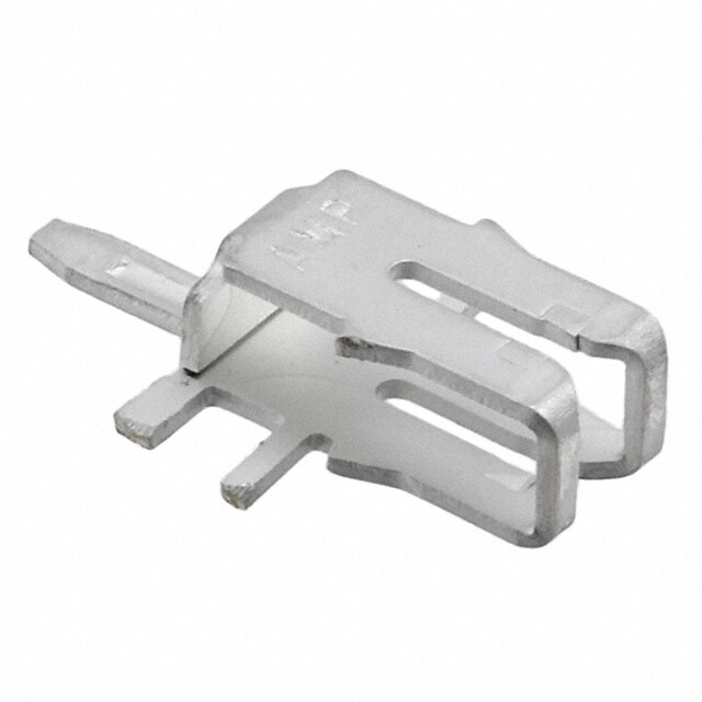
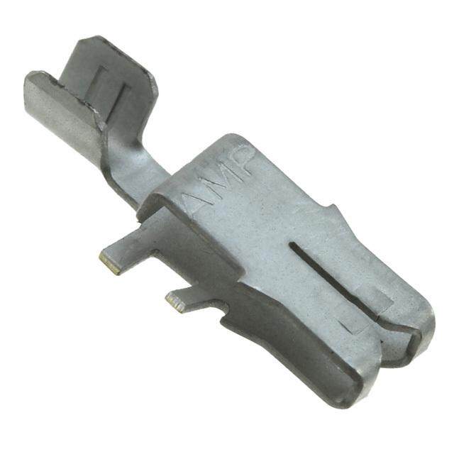
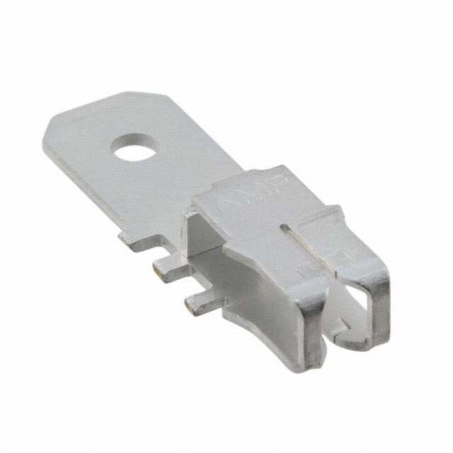
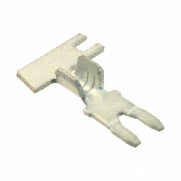
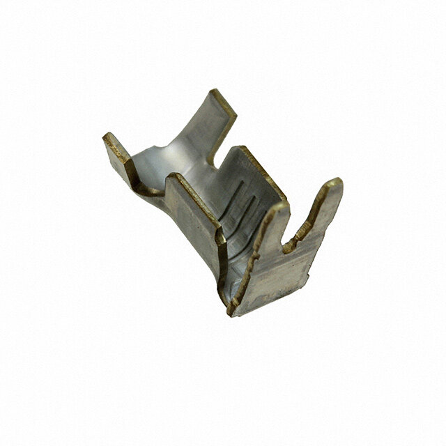
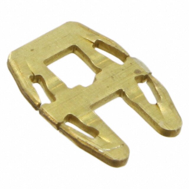
Magnet Wire Terminals and Termination Systems Catalog 82221 Standard MAG-MATE Terminals (Continued) Poke-In Tab Terminals Material .135 TS Tin plated brass [ 3.43 ] ermtan [ .31.3453 ].312 [ .31.3453 ] inalsdard M [ 7.92 ].275 A [ 6.98 ] G - M .312 A [ 7.92 ].275 .255 T [ 6.98 ] [ 6.48 ] E .405 [ 10.29 ] .323 .203 [ 8.20 ] [ 5.28 ] A B C Lead Wire Size1 Stock Strip #20 OApWtioGn [a0l .S8 lmotm fo] rDia. Type AWG mm2 Ins. O.D. Thickness Part Number .135 Solid Copper Diode Slot .018 62895-1* [ 3.43 ] A 0.46 90° Up 22-18 0.3-0.9 .020 63410-1 0.51 .255 24 0.2 .10.4002--.10.6502 .00.1486 1742828-1 [ 6.48 ] B .060-.100 .018 90° Up 22-18 0.3-0.9 62896-1* .520 1.52-2.54 0.46 w/Ins. Sup. [ 13.21 ] .090-.140 .018 18-14 0.8-2.0 63218-1 2.29-3.56 0.46 22-18 0.3-0.9 .020 62897-1* C 0.51 Straight 18-14 0.8-2.0 .020 63775-1 0.51 D 22-18 0.3-0.9 .060-.100 .020 62898-1* 1.52-2.54 0.51 .090-.140 .020 18-14 0.8-2.0 63397-1 2.29-3.56 0.51 .208 [ 5.28 ] 22-17 0.3-1.0 .118 MAX. .018 281622-22 3.00 MAX. 0.45 D Straight w/Ins. Sup. 22-17 0.3-1.0 .118 MAX. .018 281623-22 .312 3.00 MAX. 0.45 [ 7.92 ] 20-17 0.5-1.0 .063-.090 .018 964101-23 1.60-2.30 0.45 .135 [ 3.43 ] 20-17 0.5-1.0 .063-.090 .018 964290-14 1.60-2.30 0.45 E .018 E 22-18 0.3-0.9 0.46 63364-1 90° Down .018 18-14 0.8-2.0 0.46 1742125-1 1Stranded,fusedstrandedorsolidleadwire. Note:Alltabterminalsacceptstranded,fusedstranded 2Canbeselectivelybentinsideapplicator.With supportflanges, or solidleadwire. can only be used in combination with modified cavity IA-84-5157 3Canbeselectivelybentinsideapplicator, Non-locking 4 Can be selectively bent inside applicator. Non-locking;use with housing * RecognizedundertheComponentProgramof UnderwritersLaboratories,Inc. 7 www.te.com/appliances
Magnet Wire Terminals and Termination Systems Catalog 82221 Standard MAG-MATE Terminals (Continued) Poke-In Tab Terminals Material .340 Tin plated brass [8.64] .245 [ 6.22 ] Pre-Tin plated brass .312 [ 7.92 ] .110 .370[ 2.79 ] .285 .540 .135 [ 9.40 ] .347 [ 7.24 ] [ 13.72 ] [ 3.43 ] [ 8.81 ] .106 [ 2.70 ] F I J .315 [ 8.00 ] Lead Wire Size1 Stock Strip .135 .197 Type AWG mm2 Ins. O.D. Thickness Part Number [ 3.43 ] [ 5.00 ] .048-.078 .020 24-20 0.2-0.5 1742410-1 1.22-1.98 0.51 F K 90° Down 22-18 0.3-0.9 .060-.100 .020 1742211-1 w/Ins. Sup. 1.52-2.54 0.51 .090-.140 .020 18-14 0.8-2.0 63458-1 .135 2.29-3.56 0.51 [ 3.43 ] I .020 Flag - 300 Box only 20-16 0.5-1.4 0.51 1217406-1 J .080-.120 .020 Flag - 500 Box only 18-14 0.8-2.0 2.03-3.05 0.51 1217324-1 .250 K .020 1987199-1 [6.35] Bridge Contact 0.51 .150 L .020 [ 3.81 ] PCB Contact 0.51 1217041-1 .490 [ 12.45 ] Note:Alltabterminalsacceptstranded,fusedstranded orsolidleadwire. .200 [ 30.48 ] L MAG-MATE Terminals with extended leaf-spring Material Pre-tinned copper alloy Copper Magnet Wire Range Stock Strip Type AWG mm Thickness Part Number .013 33-30 0.18-0.265 0.32 1740603-1 .013 30-26 0.265-0.40 1740698-2 M 0.32 [ 1.535.9] [ 1.401.3] Meaxgte-Mndaeted TLeeramf-iSnaplr iwngith 26.5-22.5 0.375-0.60 .00.1332 1534110-1 .013 22.5-20 0.60-0.80 0.32 969125-1* .013 19.5-17 0.85-1.12 0.32 1418686-1 *Single magnet wire Note:Specialcavityisrequired,contactTEconnectivity forinformation. .120 .136 [ 3.05] [ 3.45] M 8 www.te.com/appliances
Magnet Wire Terminals and Termination Systems Catalog 82221 Standard MAG-MATE Terminals (Continued) 300 Box Poke-In Terminals TS Material erta mn Tin plated brass inda .T3y0p0ic [a7l. 6C2a]v Sitye rSieizse B 2ox .300 alsrd M [ 7.62 ] A (See page 23) .300 G [ 7.62 ] -M Note:Special cavity required for A T Tri-slot splice terminal. .120 .455 E See application [ .31.3453 ] [ 3.05 ] [ 11.56 ] [ .31.2005 ] SPEC 114-2046 A B Copper Magnet Wire Range1 Stock Strip Type AWG mm Thickness Part Number A 22-20 0.64-0.81 .016 1217973-1 300 Box 0.41 StanSdpalircde IDC 19-17 0.91-1.15 .00.2501 1742159-14 28-24 0.32-0.51 .016 1217858-1 0.41 23-202 0.57-0.81 .00.1461 1217853-1 B 300 Box 27-23 0.36-0.57 Standard IDC 184 0.8-0.9 .016 1217613-1 Tri-Slot 0.41 Splice 19-172 0.91-1.15 25-223 0.45-0.64 184 0.8-0.9 .00.1461 1217209-1 23.5-202 0.54-0.81 1Twomagnetwiresmaybeterminatedinthesameterminalslotifdiametersareequal. 2Singlemagnetwireonly; 22AWG[0.64mm]orlarger. 3Singlesolidorfusedstrandedleadwireonly. 4Specialcavityrequiredfor1742159-1. Tab Receptacle Terminals Material Tin plated phos. bronze .345 [8.76] .185 Note:Special cavity required. [4.70] Contact TE Engineering for .110 details. [2.79] .070 [1.78] C Copper Magnet Wire Range1 Stock Strip Type Mating Tab AWG mm Thickness Part Number .070 x .020 .010 32-31 0.20-0.23 1.78 x 0.51 0.25 1217538-1 C .070 x .020 .010 185 Box 30-28 0.25-0.32 1.78 x 0.51 0.25 1217457-1 Standard IDC .070 x .020 .010 Tab Receptacle 29-28 0.29-0.32 1.78 x 0.51 0.25 1217458-1 .070 x .020 .010 28-27 0.32-0.36 1.78 x 0.51 0.25 1742781-1 1Twomagnetwiresmaybeterminatedinthe sameslotifdiametersareequal. 9 www.te.com/appliances
Magnet Wire Terminals and Termination Systems Catalog 82221 Standard MAG-MATE Terminals (Continued) 187 Box F-Crimp Terminals Material Tin plated brass .T1y8p7ica[4l C.7a5v]it yS Seirziee s1 Box [ .93.6104 ][ .41.8775 ] [ .41.8775 ] [ 1.41.6876 ] (See page 23) .090 .070 .090 .070 [ 2.29 ] [ 1.78 ] [ 2.29 ] [ 1.78 ] A B Copper Magnet Wire Range1 Lead Wire Range3 Stock Strip Type Ins. O.D. AWG mm AWG mm2 Thickness Part Number .010 33-31 0.18-0.23 26-22 0.12-0.3 0.25 63039-1 .012 A 30-28 0.25-0.32 26-22 0.12-0.3 0.30 63036-1 Sta1n8d7aBrdoIxDC 27-25 0.36-0.46 26-22 0.12-0.3 .00.1320 62609-14 F-Crimp .012 26-24 0.40-0.51 22-18 0.3-1.0 0.30 1217146-1 24-222 0.51-0.64 26-22 0.12-0.3 .00.1320 62610-14 B .071-.088 .012 187BoxF-Crimp 27-25 0.36-0.46 22-18 0.3-1.0 63856-1 1.80 -2.23 0.30 w/InsSup. 1Twomagnetwiresmaybeterminatedinthesameterminalslotifdiametersareequal. 2Singlemagnetwireonly. 3Stranded,fusedstrandedorsolidleadwire. 4Striprereeledtofeedthroughmini-applicatortocrimpleadwirefirst,magnetwireterminationissecondaryoperation. 300 Box F-Crimp Terminals Material Copper Magnet Wire Range1 Dim. Lead Wire Range3 Stock Strip Type Tin plated brass AWG mm C AWG mm2 Thickness Part Number .300[7.62] Series Box .10.7708 22-18 0.3-1.0 .00.1320 63235-1 Typical Cavity Size 2, when 33-31 0.18-0.23 .120 .012 “C” dimension is .120 [3.05] 3.05 24-20 0.2-0.6 0.30 63420-1 .070 .012 (See page 23) 1.78 22-18 0.3-1.0 0.30 63236-1 31-28 0.23-0.32 Typical Cavity Size 6, when “C” .070 .012 dimension is .070 [1.78] 1.78 24-20 0.2-0.6 0.30 1742614-1 .120 .012 (See page 23) C 30-27 0.25-0.36 3.05 24-20 0.2-0.6 0.30 62992-1 300 Box .120 .012 Standard IDC 28-24 0.32-0.51 3.05 24-20 0.2-0.6 0.30 63641-1 F-Crimp .070 .012 27-24 0.36-0.51 1.78 22-18 0.3-1.0 0.30 63237-1 .480 .120 .016 [ 12.19 ] 27-23 0.36-0.57 3.05 24-20 0.2-0.6 0.41 62459-1 .070 .012 .300 25-22 0.45-0.64 1.78 22-18 0.3-1.0 0.30 63690-1 [ 7.62 ] 22-202 0.64-0.81 .31.2005 24-20 0.2-0.6 .00.1461 62458-1 19-172 0.91-1.15 .31.2005 22-18 0.3-1.0 .00.1461 63504-1 .135 1Twomagnetwiresmaybeterminatedinthe sameterminalslotifdiametersareequal. [ 3.43 ] 2Singlemagnetwireonly; 22AWG[0.64mm]orlarger. C 3Stranded,fusedstrandedor solidleadwire. 10 www.te.com/appliances
Magnet Wire Terminals and Termination Systems Catalog 82221 Standard MAG-MATE Terminals (Continued) 300 Box Posted PCB Terminals TS Multi-Spring ermtan Solderless Terminal inda L alsrd M Material A .300 G- Tin over Copper Alloy [ 7.62 ] M A TE Cavity Size .132 .120 Application Spec. [ 3.35 ] [ 3.05 ] 114-74109 with 114-74109-5 A Copper Magnet Wire Range1 Dim Stock Thickness Strip Type AWG mm L Tab Section Mag Wire Section Part Number .583 .031 .013 33-29.5 0.18-0.265 14.80 0.80 0.32 1247000-2 .583 .031 .013 A 29.5-26 0.265-0.40 14.80 0.80 0.32 1247001-2 Multi-Spring .583 .031 .013 Solderless PCB 26-22.5 0.40-0.63 14.80 0.80 0.32 1247002-2 Tab Terminal 22.5-19.52 0.63-0.85 1.548.830 .00.3810 .00.1332 1247003-2 19.5-172 0.85-1.12 1.548.830 .00.3810 .00.1332 1247004-2 1Twomagnetwiresmaybeterminatedinthesameterminalslotifdiametersareequal. Note:PCBoardholesize.057[1.45]. 2Singlemagnetwireonly. 22awg[0.63mm]andlarger. 300 Box Posted PCB .042 Terminals [ 1.07 ] Solder Terminal L L Material .300 .300 Tin over copper plated brass [ 7.62 ] [ 7.62 ] Typical Cavity Size .070 .135 (See page 23) .135 .120 [ 3.43 ] [ 1.78 ] Type C—Cavity Size 2 [ 3.43 ] [ 3.05 ] Type D—Cavity Size 6 B C Copper Magnet Wire Range1 Dim. Stock Thickness Strip Type AWG mm L Tab Section Mag Wire Part Number .540 .010 .010 33-31 0.18-0.23 13.72 0.25 0.25 63253-1 .540 .010 .010 31-28 0.23-0.32 62928-1* 13.72 0.25 0.25 300BBox 29-26 0.29-0.40 1.534.702 .00.1320 .00.1320 62958-1* StandardIDC .460 .016 .016 PCBPost 27-23 0.36-0.57 11.68 0.41 0.41 63659-1 22-202 0.64-0.81 .460 .016 .016 63660-1 11.68 0.41 0.41 19-172 0.91-1.15 .460 .016 .016 63661-1 11.68 0.41 0.41 19-172 0.91-1.15 1.547.408 .00.1461 .00.1461 1742708-1 C PCBPost 33-31 0.18-0.23 .475 .020 .012 1217302-1 ShallowBox 12.07 0.51 0.30 1Twomagnetwiresmaybeterminatedinthesameterminalslot Note:PCBoardhole size.050[1.27]. ifdiametersareequal. 2Singlemagnetwireonly. * RecognizedundertheComponentProgramofUnderwritersLaboratories,Inc. 11 www.te.com/appliances
Magnet Wire Terminals and Termination Systems Catalog 82221 Standard MAG-MATE Terminals (Continued) MAG-MATE Edge Leaf Terminal Material Pre-tinned brass Brass Cavity 411-18517 Copper Magnet Wire Range Stock Strip Cavity Size AWG mm Thickness Part Number 16.2 33-30 0.18-0.265 2 .00.1332 1394429-2 .013 30-26 0.265-0.40 2 1394430-2 A 0.32 MAG-MATE .013 26-22 0.40-0.63 2 1394431-2 Contact RAST 5D 0.32 .013 7.6 22-20 0.63-0.80 2 0.32 1394432-2 .013 20-17 0.85-1.12 2 0.32 1394433-2 3 3.15 Note:Specialcavityrequired.Contact A TEConnectivityforinformation Material Unplated brass Cavity 411-18517 Copper Magnet Wire Range Stock Strip Type Cavity Size AWG mm Thickness Part Number B MAG-MATE 33-30 0.18-0.265 2 .013 1-1987143-1 .64 0.32 [ 16.2] Edge Leaf Contact Note:Specialcavityrequired.Contact TEConnectivityforinformation .31 [ 7.8] .12 [ 3.0] B 12 www.te.com/appliances
Magnet Wire Terminals and Termination Systems Catalog 82221 Standard MAG-MATE Terminals (Continued) 187 Box Posted PCB Terminals Material Type C o pApWeGr Magnet Wi r me mRange1 DiLm. Stock Thickness PartS Ntruipmber TerSta Tin plated brass .62.6778 .00.1205 63565-1 minnda 33-31 0.18-0.23 ar Typical Cavity Size 1 .83.3308 .00.1205 62938-1 lsd M A (See page 23) .62.6778 .00.1320 63160-1 G-M 30-28 0.25-0.32 .287 .012 A 185ABox 7.29 0.30 63818-1 TE StandardIDC .330 .012 62430-1 .050 PCBPost 8.38 0.30 [1.27] 27-25 0.36-0.46 .330 .012 62438-1 8.38 0.30 L .187 .287 .012 63819-1 [4.75] 24-222 0.51-0.64 7.29 0.30 .330 .012 62439-1 8.38 0.30 1Twomagnetwiresmaybeterminatedinthesameterminalslotifdiametersareequal. 2Singlemagnetwireonly. .090 [2.29] .070 [1.78] A 187 Box Tab Terminals Material Tin plated brass Copper Magnet Wire Range1 Dim. Stock Thickness Strip Typical Cavity Size 1 Type AWG mm L Tab Size Tab Section Mag Wire Part Number .432 .110x.020 .020 .012 (See page 23) 30-28 0.25-0.32 10.97 2.79x0.51 0.51 0.30 63702-1 .432 .110x.020 .020 .012 29-27 0.29-0.36 1217196-1 10.97 2.79x0.51 0.51 0.30 .512 .110x.020 .020 .012 30-28 0.25-0.32 160810-2 B 13.00 2.79x0.51 0.51 0.30 187Box .512 .110x.020 .020 .012 27-25 0.25-0.32 160809-2 StandardIDC 13.00 2.79x0.51 0.51 0.30 F-Crimp .512 .110x.020 .020 .012 24-22 0.25-0.32 160897-2 13.00 2.79x0.51 0.51 0.30 L .550 .071 x .025 .025 .012 30 0.25 1217405-1 14.00 1.80 x 0.63 0.63 0.30 .700 .059 x .032 .032 .012 29-27 0.29-0.36 1742605-1 .187 17.78 1.50 x 0.81 0.81 0.30 .090 [4.75] 25-222 0.46-0.64 1.770.708 .10.5590 xx .00.3821 .00.3821 .00.1320 1217013-1 [2.29] 1Twomagnetwiresmaybeterminatedinthesameterminalifdiametersareequal. .070 [1.78] 2Singlemagnetwireonly. B 13 www.te.com/appliances
Magnet Wire Terminals and Termination Systems Catalog 82221 Standard MAG-MATE Terminals (Continued) 300 Box Tab Terminals Material Tin plated brass .870 [22.1] Typical Cavity Size 2 L (See page 23) .300 .300 [7.62] [7.62] .135 [3.43] .120 .135 C [3.05] [1.78] A B Copper Magnet Wire Range1 Dim. Stock Thickness Strip Type AWG mm L Tab Size Tab Section Mag Wire Part Number .750 .063x.025 .025 .016 19.05 1.60x0.63 0.63 0.41 63965-12 A 20 0.79 300Box .895 .063 x .025 .025 .016 1217595-12 StandardIDC 22.73 1.60 x 0.63 0.63 0.41 StraightTab .870 .062 x .032 .032 .010 31 0.23 22.10 1.57 x 0.81 0.81 0.25 63810-1 1Twomagnetwiresmaybeterminatedinthe sameterminalslotifdiametersareequal. 2Tinselwireonly. Copper Magnet Wire Range1 Dim. Stock Thickness Strip TypicalCavitySize2 Type AWG mm C Tab Size Tab Section Mag Wire Part Number when“C”dimensionis.120[3.05] 33-31 0.18-0.23 .070 .125x.020 .020 .012 63806-1 (Seepage23) 1.78 3.17x0.51 0.51 0.30 TypicalCavitySize6 31-28 0.23-0.32 .10.7708 .31.2157xx.00.2501 .00.2501 .00.1320 63807-1 when“C”dimensionis.070[1.78] B (Seepage23) Sta3n0d0aBrdoIxDC 27-24 0.36-0.50 .10.7708 .31.2157xx0.0.5201 .00.2501 .00.1320 63808-1 TwistedTab 212 0.72 .120 .118 x .030 .030 .016 63463-1 3.05 3.00 x 0.76 0.76 0.41 19.52 0.86 .120 .118 x .030 .030 .016 63216-1 3.05 3.00 x 0.76 0.76 0.41 1Twomagnetwiresmaybeterminatedinthesameterminalslotifdiametersareequal. 2Singlemagnetwireonly. Material Copper Magnet Wire Range1 Dim. Stock Thickness Strip Tin plated brass Type AWG mm L Tab Size Tab Section Mag Wire Part Number .585 .118x.020 .020 .010 33-31 0.18-0.23 1217746-1 Typical Cavity Size 2 14.86 3.00x0.51 0.51 0.25 (See page 23) 30 -28 0.25-0.32 .585 .118x.020 .020 .010 1217745-1 14.86 3.00x0.51 0.51 0.25 .585 .118x.020 .020 .016 63973-1 14.86 3.00x0.51 0.51 0.41 27-23 0.36-0.57 .585 .125 x .020 .020 .016 63489-1 14.86 3.17 x 0.51 0.51 0.41 C 300Box 25-222 0.45-0.64 .585 .118 x .020 .020 .016 1217596-1 StandardIDC 14.86 3.00 x 0.51 0.51 0.41 L TimerTab 23.5-21.52 0.54-0.68 1.548.856 .31.1080 xx .00.2501 .00.2501 .00.1461 1217593-1 .775 .125 x .020 .020 .016 27-23 0.36-0.57 1742167-1 19.68 3.17 x 0.51 0.51 0.41 .300 [7.62] 23-202 0.57-0.81 .775 .125 x .020 .020 .016 63899-1 19.68 3.17 x 0.51 0.51 0.41 19-172 0.91-1.15 .585 .118 x .020 .020 .016 63972-1 14.86 3.00 x 0.51 0.51 0.41 .120 [.31.3325] [3.05] 18 Lead 1.02 .585 .118 x .020 .020 .016 63974-1 14.86 3.00 x 0.51 0.51 0.41 1Two magnet wires maybeterminatedinthesameterminalslotifdiameters areequal. C 2Singlemagnet wireonly;22AWG[0.64mm]orlarger. 14 www.te.com/appliances
Magnet Wire Terminals and Termination Systems Catalog 82221 Standard MAG-MATE Terminals (Continued) Pin Receptacle Terminals TS Material .75 erta mn A: Tin plated brass .748 [ 19] inda B: Unplated brass [19] alsrd M .30 Typical Cavity Size 2 [.73.0602] [ 7.6] AG (See page 23) -M A T [.31.3325] .120 E [3.05] .12 .138 [ 3.0] [ 3.5] A B Copper Magnet Wire Range1 Strip Type Mating Pin Dia. Stock Thickness AWG mm Part Number .079 .013 30-27 0.25-0.36 2.00 0.32 1394403-1 .079 .013 26-23 0.40-0.57 2.00 0.32 1394475-1 PAin 21-182 0.72-1.00 .20.7090 .00.1332 1394476-1 Receptacle .150 .013 26-23 0.40-0.57 3.80 0.32 1394638-1 21-182 0.72-1.00 .150 .013 1394639-1 3.80 0.32 .150 .013 30-27 0.25-0.36 3.80 0.32 1740417-1 B .150 .013 Pin 26-23 0.40-0.57 3.80 0.32 1740418-1 Receptacle 21-183 0.72-1.00 .31.5800 .00.1332 1740419-1 1Twomagnetwiresmaybeterminatedinthesameterminalslotifdiametersareequal. 2Singlemagnetwireonly;20.5AWG[0.76mm]orlarger. 3 Single magnet wire only 15 www.te.com/appliances
Magnet Wire Terminals and Termination Systems Catalog 82221 Standard MAG-MATE Terminals (Continued) Pin I/O Terminals Material .048 Tin plated brass .060 [1.22] [1.52] .300[7.62] Series Box Styles A, B and C Typical Cavity Size 2 .668 .789 .300 [16.76] (See page 23) [20.29] [7.62] .300 .500 [12.7] Series Box [7.62] Style D .120 Typical Cavity Size 4 [3.05] .135 (See page 23) [3.43] .120 .120 [3.05] [3.05] A B .048 .090 [1.22] [2.29] .300 .660 .500 .860 [7.62] [16.76] [17.7] [21.84] .120 .280 [3.05] [7.11] .120 .120 [3.05] [3.05] C D Copper Magnet Wire Range1 Pin Stock Thickness Strip Type AWG mm Dia. I/O Mag Wire Part Number A .060 .010 .010 300Box 27-23 0.36-0.57 63722-1 1.52 0.25 0.25 StraightPin B .048 .010 .010 300Box 33-31 0.18-0.23 63443-1 1.22 0.25 0.25 OffsetPin-R.H. .048 .010 .010 33-31 0.18-0.23 63444-1 1.22 0.25 0.25 .048 .010 .010 C 31-28 0.23-0.32 1.22 0.25 0.25 63569-1 300Box OffsetPin-L.H. 27-23 0.36-0.57 .10.4282 .00.1205 .00.1265 63570-1 25-222 0.45-0.64 .10.4282 .00.1205 .00.1461 63788-1 D 27-23 0.86-1.15 .20.9209 .00.1461 .00.1461 63278-1 500Box StraightPin 22-20 0.64-0.81 .20.9209 .00.1461 .00.1461 63277-1 1Twomagnetwiresmaybeterminatedinthe sameterminalslotifdiametersareequal. 2Singlemagnetwireonly; 22AWG[0.64mm]orlarger. 16 www.te.com/appliances
Magnet Wire Terminals and Termination Systems Catalog 82221 Standard MAG-MATE Terminals (Continued) 110 Series FASTON Tab Terminals TS erta Material mn inda Tin plated brass .625 .625 [1.666.706] alsrd M [15.88] [15.88] A Typical Cavity Size 2 .300 .310 G- (See page 23) [7.62] [7.87] MA T E Note:.110[2.79] Tab Terminals .300 mate with compatible .135 [7.62] [3.43] FASTON receptacles. Request Catalog 82004. [.31.3453] [.31.2005] [.31.2005] [.31.3453] [.31.2005] A B C Copper Magnet Wire Range1 Tab Stock Thickness Strip Type AWG mm Size Tab Mag Wire Part Number .110 x .020 .020 .012 30-27 0.25-0.36 63777-1 2.79 x 0.51 0.51 0.30 A4 .110x.020 .020 .016 300Box 27-23 0.36-0.57 2.79x0.51 0.51 0.41 63746-1 StandardIDC .110[2.79] 23-202 0.45-0.64 .110x.020 .020 .016 63486-1 2.79x0.51 0.51 0.41 FASTONTab .110x.020 .020 .020 19-17 0.91-1.15 63145-1 2.79x0.51 0.51 0.51 B4.5 27-23 0.36-0.57 .110x.020 .020 .016 63827-1 300Box 2.79x0.51 0.51 0.41 SingleIDCw/ 3.5-202 0.54-0.81 .110x.020 .020 .016 1217783-1 StrainReliefSlot 2.79x0.51 0.51 0.41 .110x.020 .020 .012 C3.4 28-24 0.32-0.51 2.79x0.51 0.51 0.30 63062-1 Poke-In CombinationTab 25-222 0.45-0.64 .110x.020 .020 .012 63063-2 2.79x0.51 0.51 0.30 1Twomagnetwiresmaybeterminatedinthesameterminalslotifdiametersareequal. 2Singlemagnetwireonly; 22AWG[0.64mm]orlarger. 3Poke-Infeatureaccepts 20-18AWG[0.5-0.8mm2]Solidorovercoatedstrandedleadwireor90°Poke-Intab. 4Afterinsertionintoplasticcavity,tabportionmustbebentover45°-90°orpottedintopreventpulloutwhenmating receptacleisdisconnected. 5Strainrelief slotforhighvibrationapplications. 17 www.te.com/appliances
Magnet Wire Terminals and Termination Systems Catalog 82221 Standard MAG-MATE Terminals (Continued) 187 Series Copper Magnet Stock Thickness FASTON Tab Terminals Type Wire Range1 DiLm. FeTaatubre Tab Size Tab Mag. Wire PartS Ntruipmber AWG mm Section Section Material .630 Dimple .187 x .020 .020 .010 62513-1* 16.00 4.75 x 0.51 0.51 0.25 Tin plated brass 33-31 0.18-0.23 .660 .187 x .020 .020 .012 Hole 63584-1 16.76 4.75 x 0.51 0.51 0.30 .187 x .020 .020 .012 Dimple 62512-1* Typical Cavity Size .630 4.75 x 0.51 0.51 0.30 30-27 0.25-0.36 (See page 23) 16.00 Dimple .187 x .032 .032 .012 62678-1†* 4.75 x 0.81 0.81 0.30 Type A—Cavity Size 2 .187 x .020 .020 .016 Dimple 62514-1* 4.75 x 0.51 0.51 0.41 .630 .187 x .020 .020 .016 16.00 Hole 4.75 x 0.51 0.51 0.41 63664-1 27-23 0.36-0.57 .187 x .020 .020 .016 63461-1 Hole or 4.75 x 0.51 0.51 0.41 Dimple A3 .660 Hole .187 x .020 .020 .016 63585-1 300Box 16.76 4.75 x 0.51 0.51 0.41 L StandardIDC .630 .187 x .020 .020 .016 .187[4.75] 23 0.57 16.00 4.75 x 0.51 0.51 0.41 63776-1 FASTON .187 x .020 .020 .016 Tab Dimple 62511-1* .300 4.75 x 0.51 0.51 0.41 [7.62] 22-202 0.64-0.81 1.663.000 Hole .41.8775 xx .00.2501 .00.2501 .00.1461 63663-1 .187 x .032 .032 .016 .120 Dimple 4.75 x 0.81 0.81 0.41 1217065-1 [3.05] .135 .187 x .032 .032 .016 [3.43] Hole 4.75 x 0.81 0.81 0.41 1217128-1 A 20-182 0.81-1.02 .630 Dimple .41.8775 xx .00.2501 .00.2501 .00.2501 62904-14 16.00 .187 x .020 .020 .020 Hole 63670-1 4.75 x 0.51 0.51 0.51 .187 x .020 .020 .020 63273-12 187 Series .630 Dimple 4.75 x 0.51 0.51 0.51 1742160-11 19-17 0.91-1.15 Combination Poke-In 16.00 Hole .187 x .020 .020 .020 63665-1 4.75 x 0.51 0.51 0.51 FASTON Terminals 1Twomagnetwiresmaybeterminatedinthesameterminalslotifdiametersareequal. 2Singlemagnetwireonly. 3Afterinsertionintoplasticcavity,tabportionmustbebentover45°-90°orpottedintopreventpulloutwhen Material matingreceptacleisdisconnected. 4Singlebarecopperwireonly. Tin plated brass * RecognizedundertheComponentProgramofUnderwritersLaboratories,Inc. †Thesepartnumbersareavailableuponspecialrequest;contactTEEngineeringfordetails. Typical Cavity Size (See page 23) Copper Magnet Stock Thickness Type B—Cavity Size 2 Type Wire Range1 DiLm. FeTaatubre Tab Size Tab Mag. Wire PartS Ntruipmber AWG mm Section Section .630 .187 x .020 .020 .010 33-31 0.81-0.23 16.00 Hole 4.75 x 0.51 0.51 0.25 63018-1 B3.4 27-222 0.35-0.63 1.663.000 w/Ho oHleole .41.8775 xx .00.2501 .00.2501 .00.1461 2-331166330000--47 Poke-In 22-192 0.64-0.89 .630 Hole .187 x .020 .020 .016 316300-5 Combination 16.00 w/o Hole 4.75 x 0.51 0.51 0.41 2-316300-8 .310 Tab 19-172 0.90-1.15 1.663.000 w/Ho oHleole .41.8775 xx .00.2501 .00.2501 .00.1461 2-331166330000--69 [7.87] 17-162 1.20-1.30 1.663.000 Hole .41.8775 xx .00.2501 .00.2501 .00.1461 6-316300-7 .135 .120 1Twomagnetwiresmaybeterminatedinthesameterminalslotifdiametersareequal. [3.43] [3.05] 2Singlemagnetwireonly;22AWG[0.64mm]orlarger. 3Poke-Infeatureaccepts20-18AWG[0.5-0.8mm2]solid,fusedstrandedleadwireor90°poke-intabterminal. 4Afterinsertionintoplasticcavity,tabportionmustbebentover45°-90°orpottedintopreventpulloutwhenmating receptacleisdisconnected. B Note:.187[4.75] Tab Terminals mate with compatible FASTON receptacles. Request Catalog 82004. Chart continued on next page 18 www.te.com/appliances
Magnet Wire Terminals and Termination Systems Catalog 82221 Standard MAG-MATE Terminals (Continued) 187 Series .187 [4.75] FASTON Tab Terminals (Continued) TerSta mn Material HDoimlep oler Dimple inadar Tin plated brass L lsd M A .300 G .300 [7.62] -M Typical Cavity Size [7.62] A T (See page 23) .120 E Type A—Cavity Size 5 [3.05] .135 .120 Type B—Cavity Size 5 [3.43] [3.05] .135 [3.43] A B Copper Magnet Stock Thickness Type Wire Range1 DiLm. FeTaatubre Tab Size Tab Mag. Wire PartS Ntruipmber AWG mm Section Section 33-31 0.18-0.23 .630 Dimple .187 x .020 .020 .010 63108-1† 16.00 4.75 x 0.51 0.51 0.25 31-28 0.23-0.32 .630 Dimple .187 x .020 .020 .010 62743-1† 16.00 4.75 x 0.51 0.51 0.25 30-27 0.25-0.36 .630 Dimple .187 x .020 .020 .012 63109-1† 16.00 4.75 x 0.51 0.51 0.30 A .630 Dimple .41.8775 xx .00.2501 .00.2501 .00.1461 63107-1 Sta3n0d0aBrdoxIDC 27-23 0.36-0.57 16.00 Dimple .187 x .020 .020 .016 1217493-1 NarrowBody 4.75 x 0.51 0.51 0.41 LatchType 23-202 0.57-0.81 .630 Dimple .187 x .020 .020 .016 63340-1 16.00 4.75 x 0.51 0.51 0.41 22-202 0.64-0.81 .630 Dimple .187 x .020 .020 .016 63429-1 16.00 4.75 x 0.51 0.51 0.41 Dimple .187 x .020 .020 .016 62888-1 19-172 0.91-1.15 1.663.000 Hole .41.8775 xx .00.2501 .00.2501 .00.1461 63782-1 4.75 x 0.51 0.51 0.41 18 lead20.80-0.92 mm2 .630 .187 x .020 .020 .016 1217592-1† 16.00 4.75 x 0.51 0.51 0.41 B3 LNaatcrrhowTyBpeodwy/ 23.5-202 0.54-0.81 1.663.000 Dimple .41.8775 xx .00.2501 .00.2501 .00.1461 1217004-1 StrainReliefSlot 1Twomagnetwiresmaybeterminatedinthesameterminalslotifdiametersareequal. 2Singlemagnetwireonly;22AWG[0.64mm]orlarger. 3Strainreliefslotforhighvibrationapplications. †Thesepartnumbersareavailableuponspecialrequest;contactTEEngineeringfordetails. Chart continued on next page 19 www.te.com/appliances
Magnet Wire Terminals and Termination Systems Catalog 82221 Standard MAG-MATE Terminals (Continued) 187 Series FASTON Tab Terminals (Continued) Material Tin plated brass Typical Cavity Size (See page 23) Type A—Cavity Size 4 Type B—Cavity Size 4 Copper Magnet Stock Thickness Type Wire Range1 DiLm. FeTaatubre Tab Size Tab Mag. Wire PartS Ntruipmber AWG mm Section Section Hole or 22-20 0.64-0.81 .830 Hole .187 x .020 .020 .020 1742819-1 Dimple 21.08 4.75 x 0.51 0.51 0.51 .830 .187 x .020 .020 .020 19-17 0.91-1.15 Hole 1742820-1 21.08 4.75 x 0.51 0.51 0.51 .187 x .020 .020 .020 Hole 63667-1 .505 4.75 x 0.51 0.51 0.51 [12.83] .830 .187 x .020 .020 .020 17.5-16 1.09-1.29 Hole 63427-1 21.08 4.75 x 0.51 0.51 0.51 A3 .187 x .032 .032 .020 .120 500Box Hole 4.75 x 0.81 0.81 0.51 1217075-1 [3.05] StandardIDC .187 x .020 .020 .020 .280 Hole 4.75 x 0.51 0.51 0.51 63666-1 [7.11] .830 .187 x .020 .020 .020 16-15 1.29-1.45 Hole 63762-1 21.08 4.75 x 0.51 0.51 0.51 A .187 x .020 .020 .020 Dimple 63353-1 4.75 x 0.51 0.51 0.51 14.5-132 1.54-1.83 .830 Hole .187 x .020 .020 .020 1217902-1 21.08 4.75 x 0.51 0.51 0.51 .830 .187 x .020 .020 .020 27-23 0.36-0.57 Hole 1217042-1 21.08 4.75 x 0.51 0.51 0.51 [.41.8775] Hole .187 x .020 .020 .020 63983-1 .830 4.75 x 0.51 0.51 0.51 22-20 0.64-0.81 L Hole B3.4 21.08 Hole .41.8775 xx .00.3821 .00.3821 .00.2501 1217339-1 500Box SingleIDCw/ .187 x .020 .020 .020 Hole 63995-1 StrainReliefSlot .830 4.75 x 0.51 0.51 0.51 19-17 0.91-1.15 .505 21.08 .187 x .032 .032 .020 [12.83] Hole 4.75 x 0.81 0.81 0.51 1217090-1 .281 [7.14] .120 16-15 1.29-1.45 .830 Hole .187 x .020 .020 .020 63996-1 [3.05] 21.08 4.75 x 0.51 0.51 0.51 1Twomagnetwiresmaybeterminatedinthesameterminalslotifdiametersareequal. B 2Singlemagnetwireonly. 3Afterinsertionintoplasticcavity,tabportionmustbebentover45°-90°orpottedintopreventpulloutwhen matingreceptacleisdisconnected. 4Strainreliefslotforhighvibrationapplications. 20 www.te.com/appliances
Magnet Wire Terminals and Termination Systems Catalog 82221 Standard MAG-MATE Terminals (Continued) 250 Series FASTON Tab Terminals Hole or TS Material HDoimlep oler L Dimple L Dimple L Locking ermintanda Tin plated brass [.73.0602] [.73.0602] [.73.0602] La(2tc)h lsard M A G T(Syepei cpaagl eC 2a3v)ity Size [.31.3453] [.31.2005] [.31.3453] [.31.2005] [.31.3453] [.31.2005] -MA T Type A—Cavity Size 2 A B C E Type B—Cavity Size 5 Copper Magnet Stock Thickness Type C—Cavity Size 3 Type Wire Range1 DiLm. FeTaatubre Tab Size Tab Mag. Wire PartS Ntruipmber AWG mm Section Section Note:.250[6.35] tab terminals 33-31 0.18-0.23 .750 Dimple .250 x .032 .032 .010 62600-1* 19.05 6.35 x 0.81 0.81 0.25 mate with compatible FASTON .750 .250 x .032 .032 .012 receptacles. Request A3 30-27 0.25-0.36 19.05 Dimple 6.35 x 0.81 0.81 0.30 62651-1* 300 Box .750 .250 x .032 .032 .016 Catalog 82004. Standard IDC 28-24 0.32-0.51 19.05 Hole 6.35 x 0.81 0.81 0.41 63607-1 .250 [6.35] FASTON 27-23 0.36-0.57 .750 Dimple .250 x .032 .032 .016 62652-1* Tab 19.05 6.35 x 0.81 0.81 0.41 .750 .250 x .032 .032 .016 22-20 0.64-0.81 Dimple 1217924-1 19.05 6.35 x 0.81 0.81 0.41 .750 .250 x .032 .032 .020 19-17 0.91-1.15 Dimple 1742398-1 19.05 6.35 x 0.81 0.81 0.51 33-31 0.18-0.231 .750 Dimple .250 x .032 .032 .010 63026-1 19.05 6.35 x 0.81 0.81 0.25 B 30-27 0.25-0.361 .750 Dimple .250 x .032 .032 .012 63027-1. Narrow 19.05 6.35 x 0.81 0.81 0.30 Body .750 .250 x .032 .032 .016 Latch Type 27-23 0.36-0.57 19.05 Dimple 6.35 x 0.81 0.81 0.41 1217860-1 23-202 0.57-0.81 .750 Dimple .250 x .032 .032 .016 1217870-1 19.05 6.35 x 0.81 0.81 0.41 .750 .250 x .032 .032 .010 33-31 0.18-0.23 Hole 63309-1 19.05 6.35 x 0.81 0.81 0.25 .750 .250 x .032 .032 .012 31-28 0.23-0.32 Dimple 63403-2 19.05 6.35 x 0.81 0.81 0.30 .750 .250 x .032 .032 .012 30-28 0.25-0.32 Hole 1217152-1 19.05 6.35 x 0.81 0.81 0.30 C Wide Body 30-27 0.25-0.36 .750 Dimple .250 x .032 .032 .012 63132-1 Latch Type 19.05 Hole 6.35 x 0.81 0.81 0.30 63499-1 .750 Hole .250 x .032 .032 .016 63571-1 27-23 0.36-0.57 19.05 Dimple 6.35 x 0.81 0.81 0.41 63128-1 22-202 0.64-0.81 .750 Dimple .250 x .032 .032 .016 63601-2 19.05 6.35 x 0.81 0.81 0.41 19-172 0.91-1.15 .750 Hole .250 x .032 .032 .016 63614-1 19.05 6.35 x 0.81 0.81 0.41 1Twomagnetwiresmaybeterminatedinthe same * RecognizedundertheComponentProgramof terminalslotifdiametersareequal. UnderwritersLaboratories,Inc. 2Singlemagnetwireonly; 22AWG[0.64mm]orlarger. 3Afterinsertionintoplasticholder,tabportionmust be bentover45°-90°orpottedintopreventpulloutwhen matingreceptacleisdisconnected. Chart continued on next page 21 www.te.com/appliances
Magnet Wire Terminals and Termination Systems Catalog 82221 Standard MAG-MATE Terminals (Continued) 250 Series FASTON Tab Terminals (Continued) Hole or Hole or Dimple Dimple Material Tin plated brass L L .500 .500 [12.7] [12.7] Typical Cavity Size (See page 23) .120 Type A—Cavity Size 4 [3.05] .120 [3.05] Type B—Cavity Size 4 .280 .280 [7.11] [7.11] A B Copper Magnet Stock Thickness Type Wire Range1 DiLm. FeTaatubre Tab Size Tab Mag. Wire PartS Ntruipmber AWG mm Section Section .952 .250 x .032 .032 .020 22-20 0.64-0.81 Hole 63495-1 24.18 6.35 x 0.81 0.81 0.51 .952 .250 x .032 .032 .020 19-17 0.91-1.15 Hole 63464-3 A3 24.18 6.35 x 0.81 0.81 0.51 500 Box .952 .250 x .032 .032 .020 Standard IDC 16-15 1.29-1.45 24.18 Hole 6.35 x 0.81 0.81 0.51 63459-2 Wide Neck .250 x .032 .032 .020 Dimple 63460-1 14-132 1.61-1.83 .952 6.35 x 0.81 0.81 0.51 24.18 .250 x .032 .032 .020 Hole 63816-1 6.35 x 0.81 0.81 0.51 .952 .250 x .032 .032 .020 22-20 0.64-0.81 Dimple 63155-1 24.18 6.35 x 0.81 0.81 0.51 .952 .250 x .032 .032 .020 B3 19-17 0.91-1.15 24.18 Dimple 6.35 x 0.81 0.81 0.51 62923-1 500 Box .952 .250 x .032 .032 .020 Standard IDC 16-15 1.29-1.45 Dimple 63064-1 24.18 6.35 x 0.81 0.81 0.51 Narrow Neck 14-132 1.61-1.83 .952 Dimple .250 x .032 .032 .020 63465-1 24.18 6.35 x 0.81 0.81 0.51 122 2.05 .952 Dimple .250 x .032 .032 .020 63425-1 24.18 6.35 x 0.81 0.81 0.51 1Twomagnetwiresmaybeterminatedinthesameterminalslotifdiametersareequal. 2Singlemagnetwireonly. 3Afterinsertionintoplasticholder,tabportionmust bebentover45°-90°orpottedintopreventpulloutwhenmating receptacleisdisconnected. 22 www.te.com/appliances
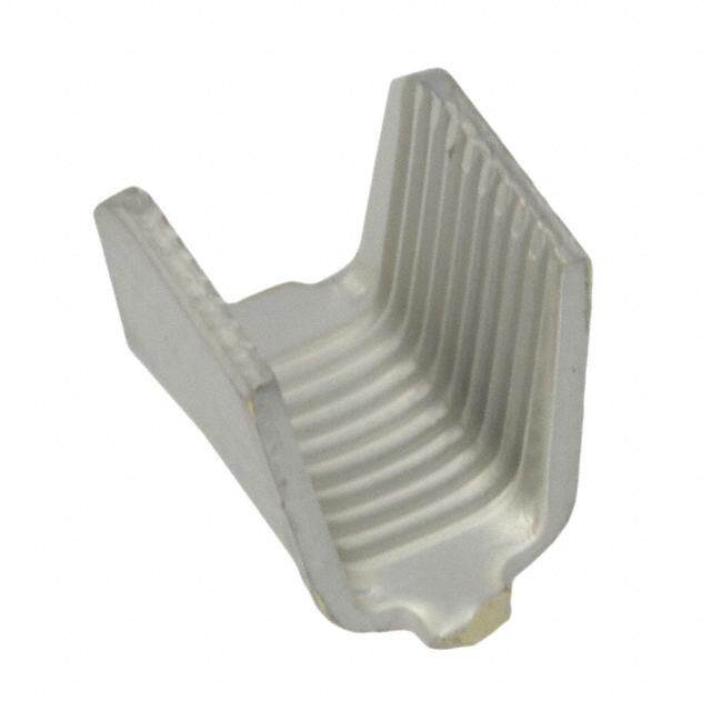
Magnet Wire Terminals and Termination Systems Catalog 82221 Standard MAG-MATE Terminals (Continued) Typical Plastic Cavity Illustrations shown are for reference only. They are not TS a purchased item. erta Mtoa TnEu fSacpteucriefi coantliyo na.ccording .235 [.93.5058] [.93.5058] minandar [5M.9in7.] Min. Min. lsd M A G - M Technical Documents AT Adepspclriicbaet iroenq uSirpeemceifnictsa tfioorn ussing [.4M1.74in55.] [.3M1.58in01.] [.5M2.14in56.] [.5M2.02in51.] [.9M3.50in58.] [.5M2.39in57.] E the product in its intended CavitySize1 CavitySize2 CavitySize3 187[4.75]Box .300[7.62]Box .300[7.62]Box application and or crimping MAG-MATE MAG-MATE Latch-In MAG-MATE Wide Body information. They are intended (ApplicationSpec.114-2069) (ApplicationSpec.114-2046) (ApplicationSpec.114-2094) for the Packaging and Design Engineer and the Machine Setup Person. 114-2050—Poke-In Tab MAG-MATE Terminals .550 114-2069—SMtAanGd-aMrAdTE.187 [1M3.in9.7] [.93.5058] [.93.5058] Min. [4.75] Box Height Min. Terminals 114-2046—Standard MAG-MATE.300 [7.62] Box Height 114-2066—STMetAarnmGd-inaMarAdlsTE.500 [.9M3.75in53.] [.7M3.06in02.] [.5M2.14in56.] [.5M2.39in57.] [.5M2.14in56.] [.3M1.58in01.] [12.7] Box Height CavitySize4 CavitySize5 CavitySize6 .500[12.70]Box .300[7.62]Box .300[7.62]Box Terminals MAG-MATE Latch-In MAG-MATE, MAG-MATE 114-2067—Standard (ApplicationSpec.114-2066) NarrowBody (ApplicationSpec.114-2046) MAG-MATE .300 (ApplicationSpec.114-2067) [7.62] Box Height Latch-In Terminals Note:The MAG-MATE Unraveling is prevented by a Excess magnet wire is Narrow Body typical plastic cavities shown slight friction fit, suitable trimmed flush with the 114-2094—Standard above are for reference only. bend or by wrapping the outside of the plastic cavity MAG-MATE .300 They are not a purchased magnet wire around a tie-off by a shear blade traveling [7.62] Box Height item. Refer to appropriate TE post. with the terminal insertion Latch-In Terminals application specification for Wide Body details. During insertion, two ram. insulation displacing terminal The sheared wire end can Plastic cavities, designed to slots strip the film insulation be tucked inside the plastic TE specifications, may be from the magnet wire cavity, if necessary, by molded as part of the coil producing a stable electrical cutting the wire off before the bobbin or attached to a termination. terminal is fully seated lamination stack in the area of the magnet wire coil. The plastic anvil supports allowing the terminal to drag the magnet wire, helping to the severed end of the wire Each cavity is a rectangular prevent it from being into the pocket inside the box with two narrow slots on dragged down when the cavity. opposing walls and a plastic terminal is inserted. TE will provide design post or anvil extending and mold engineering upward from the bottom Terminal retention is secured resources to manufac- surface. During or after the in the plastic cavities by ture any specifically winding process, the magnet either locking barbs or designed MAG-MATE wire is placed across the locking latches in addition to cavity housing. plastic cavities and into the locking barbs for quick slots, either manually or by disconnect FASTON tab coil winding equipment. terminals. 23 www.te.com/appliances
Magnet Wire Terminals and Termination Systems Catalog 82221 Standard MAG-MATE Terminals (Continued) Typical Plastic Cavities Illustrations shown are for reference only. They are not a purchased item. Manufacture only according .375 to TE Specification. [9.53] Min. .375 [9.53] Min. .225 [.62.7806] [.21.1952] [5M.7in1.] Min. Min. .250 [6.35] Min. SlimLineMAG-MATE MiniMAG-MATE ReferenceApplication ReferenceApplication Spec.114-2147 Spec.114-2047 Technical Documents Technical Documents Application Specifications Application Specifications describe requirements for using describe requirements for using the product in its intended the product in its intended application and or crimping application and or crimping information. They are intended information. They are intended for the Packaging and Design for the Packaging and Design Engineer and the Machine Engineer and the Machine Setup Person. Setup Person. 114-2140—Slim Line 114-2047—Mini MAG-MATE MAG-MATE Terminals Terminals 24 www.te.com/appliances
Magnet Wire Terminals and Termination Systems Catalog 82221 Slim Line MAG-MATE Terminals Product Facts Terminates all magnet wire film insulations TS ermlim Eplriem-sintraitpepsi nnge ecdo nfodru ctors ina Lin lse M Eliminates need to A post-insulate terminations G- M Excess magnet wire is A T automatically trimmed during E the termination process 187 and 250 Series Faston Tab and posted PCB Tab terminals available Terminates 33-17 AWG [0.18-1.15 mm ] magnet wire Simultaneously terminates two magnet wires of the same size in one terminal from 33-23 AWG [0.18-0.57 mm] Available in strip form for semi-automatic or fully automatic insertions TE offers a full selection of The MAG-MATE Inserter This constant pressure High speed, fully automated 187 and 250 Series Faston cuts the terminals from the results in an intimate integrated systems provide and posted PCB Slim Line strip and places the termi- metal-to-metal interface, uniform terminations MAG-MATE Tab insulation nals over the magnet wire providing a reliable, long- reliably at the lowest displacement(IDC) termi- into the plastic cavities. term connection. possible applied cost nals for magnet wire During this operation, small The MAG-MATE terminations. Clean metal-to-metal stripping shoulders in the Inserter may be used as a interface produces stable, Slim Line MAG-MATE IDC slot remove the film semi-automatic bench gas-tight electrical termina- terminals with a single IDC insulation from the magnet machine or integrated in tions free of oxides and slot terminate 33-17 AWG wire. production lines for other contaminants [0.18 to 1.15 mm]. fully-automatic applications. Wiping action between Recognized under the Each IDC slot terminates the wire and terminals Component Recognition a range of up to four removes oxides or other Program of Underwriters consecutive magnet wire contaminants present on Laboratories Inc., sizes. both the conductor and the File No. E13288 R terminal slot side walls, Two magnet wires with the producing a clean, stable, Applications same diameter can be gas-tight electrical termina- terminated in one terminal. Motor windings and tion. Except as noted. connections MAG-MATE cavities are Residual spring energy in Coil Connections either integrated into coil the terminal causes the side Transformer windings and bodies or especially walls of each IDC slot to connections designed cavity housings. function as opposing Bobbin connections The magnet wires are cantilever beams. precisely positioned in the Lighting Ballasts plastic cavity slots. Power Supplies 25 www.te.com/appliances
Magnet Wire Terminals and Termination Systems Catalog 82221 Slim Line MAG-MATE Terminals (Continued) 187Series FASTONTabTerminals Material Tin plated brass Copper Magnet Stock Thickness Type Wire Range1 DiLm. FeTaatubre Tab Size Tab Mag.Wire PartS Ntruipmber .187 AWG mm Section Section [4.75] Hole .187 x .020 .020 .012 63710-2 .020 [0.51] 33-31 0.18-0.23 .630 Dimple 4.75 x 0.51 0.51 0.30 63738-2 16.00 .187 x .032 .032 .012 Hole or Hole 4.75 x 0.81 0.81 0.30 1217666-1 Dimple .630 Hole .187 x .020 .020 .012 63711-2 30-28 0.25-0.32 16.00 Dimple 4.75 x 0.51 0.51 0.30 63737-2 .630 Hole .187 x .020 .020 .016 63712-2 L .187A[4.75] 27-24 0.36-0.51 16.00 Dimple 4.75 x 0.51 0.51 0.41 63736-2 FASTON Tab .760 Plain .187 x .020 .020 .016 1217497-1 19.31 4.75 x 0.51 0.51 0.41 Hole .187 x .020 .020 .016 63713-2 [.31.3453] 23-202 0.57-0.81 1.663.000 Dimple .41.8775 xx .00.3521 .00.3521 .00.1461 63735-2 .016 Hole 1217516-1 [0.41] 4.75 x 0.81 0.81 0.41 19-172 0.91-1.15 .630 Hole .187 x .020 .020 .016 63714-2 A 16.00 Dimple 4.75 x 0.51 0.51 0.41 63734-2 1 Two magnet wires may be terminated in the same terminal slot if diameters are equal. 2 Single magnet wire only; 22 AWG [0.64] or larger. 250Series FASTONTabTerminals Material Tin plated brass Copper Magnet Stock Thickness .250 Type Wire Range1 DiLm. FeTaatubre Tab Size Tab Mag.Wire PartS Ntruipmber [6.35] AWG mm Section Section .032 .752 Hole .250 x .032 .032 .012 63716-2 [0.81] 33-31 0.18-0.23 19.10 Dimple 6.35 x 0.81 0.81 0.30 63744-2 .752 Hole .250 x .032 .032 .012 63717-2 30-28 0.25-0.32 Hole or 19.10 Dimple 6.35 x 0.81 0.81 0.30 63743-2 Dimple B .250[6.35] 27-24 0.36-0.51 .752 Hole .250 x .032 .032 .016 63718-2 19.10 Dimple 6.35 x 0.81 0.81 0.41 63742-2 FASTON Tab L 23-202 0.57-0.81 1.795.120 DHimoplele .62.5305 xx .00.3821 .00.3821 .00.1461 6633771491--22 19-172 0.91-1.15 .752 Hole .250 x .032 .032 .016 63720-2 19.10 Dimple 6.35 x 0.81 0.81 0.41 63740-2 .135 1 Two magnet wires may be terminated in the same terminal slot if diameters are equal. [3.43] 2 Single magnet wire only; 22 AWG [0.64] or larger. .016 [0.41] B PostedPCB SOLDERTerminal Material Copper Magnet Stock Thickness Tin plated brass Type Wire Range1 DiLm. FeTaatubre Tab Size Tab Mag.Wire PartS Ntruipmber AWG mm Section Section .323 .040 x .024 .024 .013 33.5-30 0.17-0.25 8.20 Embossment 1.00 x 0.60 0.60 0.32 1534684-1 .323 .040 x .024 .024 .013 .0322 C 29.5-26 0.27-0.40 8.20 Embossment 1.00 x 0.60 0.60 0.32 1534685-1 [8.20] .0P4C0B[ 1T.0a0b] 26-22 0.40-0.63 8.3.2203 Embossment 1.0.0400 xx .00.2640 0.0.6204 0.0.3123 1534686-1 .323 .040 x .024 .024 .013 22-20 0.63-0.81 8.20 Embossment 1.00 x 0.60 0.60 0.32 1740829-1 .0125 21.5-19.5 0.67-0.85 8.3.2203 Embossment 1.0.0400 xx .00.2640 0.0.6204 0.0.3123 1534687-1 [.31.3425] [0.32] 1 Two magnet wires may be terminated in the same terminal slot if diameters are equal. C 2 Single magnet wire only; 22 AWG [0.64] or larger. 26 www.te.com/appliances
Magnet Wire Terminals and Termination Systems Catalog 82221 Slim Line MAG-MATE Terminals (Continued) OffsetTabTerminals MTAlipnap tPleiclraaitateioldn Bs rwashsere I/O Tab TerminaSlim Lin spacing must be less than lse M IDC connection spacing A G Example: automotive -M accessory coils A T E .139 [3.53] .032 [0.81] .059 [1.50] Copper Magnet Stock Thickness .135 L Type Wire Range1 DiLm. DSioizdee Tab Size Tab Mag.Wire PartS Ntruipmber [3.43] AWG mm Section Section .725 #20 .059 x .032 0.032 0.012 A 33-31 0.18-0.23 63888-1 18.42 0.8 1.50 x 0.81 0.81 0.30 Combination [.52.2509] Diode Slot/Tab 33-31 0.18-0.23 1.782.452 #202.6.5 .10.5590 xx .00.3821 00.0.8312 00.0.3102 63903-1 .013 [0.33] 1 Two magnet wires may be terminated in the same terminal slot if diameters are equal. A PostedPCBTerminals Multi-SpringSolderless Terminal Material Tin Plated Copper Alloy CavitySize Application Spec. Contact TE Engineering Copper Magnet Stock Thickness Type Wire Range1 DiLm. Tab Mag.Wire PartS Ntruipmber AWG mm Section Section .583 .031 .013 33-29.5 0.18-0.265 2120743-2 14.80 0.81 0.32 .583 .031 .013 L B 29.5-26 0.265-0.40 14.80 0.81 0.32 2120744-2 Multi-Spring .583 .031 .013 26-22.5 0.40-0.63 2120745-2 Solderless PCB 14.80 0.81 0.32 [.92.8393] Tab Terminal 22.5-19.52 0.63-0.85 .583 .031 .013 2120746-2 14.80 0.81 0.32 19.5-172 0.85-1.12 .583 .031 .013 2120747-2 14.80 0.81 0.32 .132 1 Two magnet wires may be terminated in the same terminal slot Note:PCBoardholesize.057[1.45] [3.35] [.00.1332] if diameters are equal. 2 Single magnet wire only. 22 awg [0.63 mm] and larger. B 27 www.te.com/appliances
Magnet Wire Terminals and Termination Systems Catalog 82221 Slim Line MAG-MATE Terminals (Continued) PostedPCB SolderTerminals Material Unplated brass Copper Magnet Wire Range Stock Strip Type AWG mm Thickness Part Number 33-30 0.256-0.40 Varied 331 0.40-0.561 thickness 1-1987222-1 30-26 0.256-0.40 Varied 30-261 0.40-0.561 thickness 1-1987223-1 A 26-22 0.40-0.63 Varied MAG-MATE 26-231 0.40-0.561 thickness 1-1987224-1 Terminal Varied with MQS Pins 22-20 0.63-0.80 thickness 1-1987225-1 Varied 20-17 0.85-1.12 1-1987226-1 thickness A 1 For double magnet wires 28 www.te.com/appliances
Magnet Wire Terminals and Termination Systems Catalog 82221 Mini MAG-MATE Terminals Product Facts Terminates all fine gauge magnet wire film TM insulations erminini M Eliminates need to pre-strip aA conductors lsG- M A Eliminates need to post T E insulate terminations Terminates 52-30 AWG [0.02-0.25 mm] diameter copper magnet wire Poke-In leaf style accepts 22 -18 AWG [0.3-0.9 mm] overcoated stranded or solid lead wire Available in strip form for semi-automatic or fully automatic insertions High speed, fully automated integrated systems provide uniform terminations and reliability at the lowest possible applied cost Recognized under the Component Recognition TE offers Mini MAG-MATE receiving slot and wire tie-off the termination process. Program of Underwriters poke-in, crimp wire post that is either integrated Laboratories Inc, File No. barrel, post and quick into coil bodies or specially The fully seated terminal fits E13288 disconnect tab insulation designed cavity housings. squarely into the cavity,while R displacement(IDC) termi- the serrated leg of the nals for fine gauge magnet The magnet wire is wrapped terminal cams against the Applications wire terminations. around the tie-off post and pre-positioned magnet wire Ignition coils placed across the cavity slot. to penetrate the film insula- Mini MAG-MATE terminals After the coil is wound, the tion and provide a stable Small motors are designed to terminate finish end of the magnet wire electrical termination. Synchronist timers 52-30 AWG [0.02-0.25 mm] is dressed through the diameter copper magnet second cavity slot and tied to Electric meter coils wire. its tie-off post. Solenoids Relays Poke-in leaf terminals accept The Mini MAG-MATE 22-18 AWG [0.3-0.9 mm2] Inserter shears the terminal overcoated stranded or solid from the carrier strip and lead wire. inserts the terminal into the cavity by a dual ram The terminal design uses the insertion mechanism. AMPLIVAR serrated burr technology to penetrate the As the unexpanded terminal film insulation of copper approaches the bottom of magnet wire. the cavity, the upper ram stops. The lower ram Mini MAG-MATE cavity continues to push to a pockets, designed to TE prescribed depth to expand specifications,include a wire the terminal and complete 29 www.te.com/appliances
Magnet Wire Terminals and Termination Systems Catalog 82221 Mini MAG-MATE Terminals (Continued) Wire Split ram Wire tie-off post Wire Upper ram stops Lower ram continues Sheared post and excess wire to scrap chute Lower ram stops Termination Complete Poke-In Terminal Material .010[0.25] tin plated brass .138 Copper Magnet Wire Range Lead Wire Range1 Mating Stock Thickness Strip [3.51] [.10.6502] Type AWG mm AWG mm2 Tab Poke-In Beam Mag Wire Part Number [.83.4756] A 52-42 0.02-0.06 22-18 0.3-0.9 — 00.0.2150 00.0.2150 62781-1 A Lead 44-36 0.05-0.13 22-18 0.3-0.9 — 0.010 0.010 62780-1 Wire 0.25 0.25 Poke-In 0.010 0.010 38-30 0.10-0.25 22-18 0.3-0.9 — 62606-1 0.25 0.25 .138 [3.51] .060 .060 x .020 0.010 0.010 [1.52] 52-42 0.02-0.06 — — 1.52 x 0.51 0.25 0.25 63613-1 [.83.4756] TBab 44-36 0.05-0.13 — — .060 x .020 0.010 0.010 63795-12 1.52 x 0.51 0.25 0.25 B Poke-In 38-30 0.10-0.25 — — .060 x .020 0.010 0.010 63844-22 1.52 x 0.51 0.25 0.25 .047 L [1.20] C 40-34.5 0.08-0.15 — — .040 x .020 0.010 0.010 1718165-1 Skinny Mini 1.00 x 0.51 0.25 0.25 1 Solid or overcoated stranded lead wire only. .345 2 Radius on beam leaf tip. [8.76] C 30 www.te.com/appliances
Magnet Wire Terminals and Termination Systems Catalog 82221 Mini MAG-MATE Terminals (Continued) PostedTerminal MTina toevreiar lpremilled brass TerminMini M aA lsG - M .138 [3.51] .060 A [1.52] T E .169 [4.29] Type Copper Magnet Wire Range Post Size Stock Thickness Strip AWG mm Post Mag Wire Part Number .540 [13.72] A .024 x .020 0.020 0.010 PCB Post 38-30 0.10-0.25 0.62 x 0.51 0.51 0.25 63675-4 A FASTONTabTerminals Material Tin over premilled brass .138 [3.51] [.10.6502] Type Copper Magnet Wire Range Tab Size Stock Thickness Strip .690 G W A m m Post Mag Wire Part Number [17.53] .187 x .020 .020 .010 B 44-36 0.05-0.13 4.75 x 0.51 0.51 0.25 63778-1 .187[4.75] FASTON Tab 38-30 0.10-0.25 .187 x .020 .020 .010 1217529-1 4.75 x 0.51 0.51 0.25 B CrimpWireBarrelTerminal Material Tin plated brass .060 .138 [1.52] Copper Magnet Wire Range Lead Wire Range Stock Thickness Strip [3.51] Type AWG mm AWG mm2 Crimp Barrel Mag Wire Part Number C Crimp Wire 38-30 0.10-0.25 22-18 0.3-0.9 00.0.2150 00.0.2150 63199-11 Barrel .620 [15.75] 1 Wire and insulation barrel reversed so lead wire exits over magnet wire termination area. C 31 www.te.com/appliances
Magnet Wire Terminals and Termination Systems Catalog 82221 SIAMEZE Terminals Product Facts Terminates all copper magnet wire film insulations Eliminates need for pre-stripping conductors Moving Beam contact design connects a wide range of magnet wire sizes with a single terminal Standard range terminals connect 34-18 AWG [0.16-1.0 mm] magnet wire Fine range terminals connect 36-27 AWG [0.13-0.38 mm] magnet wire Medium range terminals connect 23-12 AWG [0.56-2.03 mm] magnet wire Excess magnet wire is automatically trimmed during the termination process Available in strip form for semi-automatic or fully TE offers a full selection of Available with either Moving Residual spring energy in automatic insertions SIAMEZE insulation Beam contacts whereby a the terminal causes the Loose piece terminals displacement(IDC) single terminal connects toa side walls of the IDC slot available for manual tool terminals for interconnect- very wide range of magnet to function as opposing insertions ing copper magnet wires, wire sizes, or a Compliant cantilever beams. lead wires, and other Beam for contacting two This constant pressure High-speed automatic coil components. magnet wires of the same results in an intimate winding machine termina- The SIAMEZE diameter in one terminal for metal-to-metal interface, tions provide uniform insulation displacement splicing or bi-filar applica- providing a reliable, reliability at the lowest (IDC) terminal technology tions. long-term connection. possible applied cost eliminates the need to strip Tab terminals are available The wiping action between Clean metal-to-metal the film insulation from with single barbs or multiple the wire and terminals interface produces stable, copper magnet wires and retention barbs for higher remove all oxides or other gas-tight electrical termina- lead wires. retention. contaminants present on tions free of oxides and Terminals are available in According to TE specifica- both the conductor and the other contaminants wire-to-wire, Lead Lok, tions SIAMEZE cavities are terminal slot side walls, quick disconnect tabs, either integrated into coil producing a clean, stable, Recognized under the posts, pin and receptacle bodies or specially gas-tight electrical Component Program of terminals. designed cavity housings. termination. Underwriters Laboratories Inc.,File No. E13288 The magnet wires are The SIAMEZE terminal positioned in the “U”shaped Inserter may be used as a R Applications slots. semi-automatic bench machine or integrated in The SIAMEZE terminal Motor windings and production lines for Inserter cuts the terminals connections fully-automatic applica- from the strip and places the Coil connections terminals over the magnet wire tions. Transformer windings and into the plastic cavities. connections During this operation the Ballasts small stripping devices penetrate the film insulation Power supplies from the magnet wire. Solenoids Actuators 32 www.te.com/appliances
Magnet Wire Terminals and Termination Systems Catalog 82221 SIAMEZE Terminals(Continued) Lead Lok Terminals Product Facts Provides perpendicular and parallel lead wire strain relief retention forces in excess of 20 lbs (90 N). Inserter automatically S positions and secures lead IA M wire during insertion E Z Manual, semi-automated, E T fully automated systems e r allow for lead wire termina- m tion in a Accepts #18-#22 [0.3mm ls 2-0.8 mm2] AWG solid or stranded lead wire with .115[2.92] max.insulation diameter No lead wire stripping required TE features the Lead cuts the Lead Lok terminals metal-to-metal interface, Lok strain relief terminal from the strip and places providing a reliable, long- system that provides the terminal over the lead termconnection. optimum lead wire retention wire in the plastic cavities. Perpendicular and parallel when used in conjunction During this operation, the lead wire strain relief retention with SIAMEZE insulation lead wire is automatically forces in excess of 20 lbs are displacement terminals. seated, the insulation achieved. After the one-step insertion pierced and the exposed The Lead Lok Inserter of SIAMEZE wire-to- solid or stranded conductor may be a secondary station in wire terminals into TE is terminated in the IDC slot the SIAMEZE Wire-to- specified plastic cavities, the of the SIAMEZE wire-to-wire Wire semi-automatic bench application is ready for the terminal. machine. secondary lead wire attach- Residual spring energy in the Information regarding terminal ment. terminal causes the side insertion equipment may be The lead wire is manually walls of the IDC slot to found in Magnet Wire Termi- positioned over the magnet function as opposing nation Overview #138516. wire terminated SIAMEZE cantilever beams. wire-to-wire terminal. This constant pressure The Lead Lok Inserter results in an intimate TECHNICAL DOCUMENTS Cavity Specifications - Provide dimensional design guidelines & criteria for a cavity to be used with a SIAMEZE IDC terminal. The appropriate Cavity Specification number is shown on the following pages adjacent to the terminal number. As a general reference, overall dimensions are shown at the end of this section. Product Specifications ( These describe the performance characteristics and verification tests ) 108-2085 Standard Range SIAMEZE Insulation Displacement 108-2293 High Temperature Standard Range SIAMEZE Insulation Displacement 108-2244 Fine Range SIAMEZE Insulation Displacement 108-2239 Medium Range SIAMEZE Insulation Displacement 108-2316 Heavy Range SIAMEZE Insulation Displacement Application Specifications ( These describe the requirements for using the product in its intended application ) 114-13166 Standard and Fine Range SIAMEZE Insulation Displacement 114-13210 Medium and Heavy Range SIAMEZE Insulation Displacement 33 www.te.com/appliances
Magnet Wire Terminals and Termination Systems Catalog 82221 SIAMEZE Terminals (Continued) SIAMEZE Interconnection System How the System Operates Magnet Wire Plastic Cavity The magnet wire is Design must comply with positioned in “U” slot TE connectivity manually or automatically specifications(for cavity by coil winding equipment. drawing numbers see tables). ConsultingTE is Terminal Insertion Finger required for design in. The terminal insertion finger is part of the Cavity Slot for Wire SIAMEZE Inserter. It The width has to be in pushes the terminal that accord ance with the wire was sheared from the size (see cavity drawings). carrier strip through Wire Cutoff Block the“tube” into the cavity. The wire cutoff block Contact supports the magnet wire Various wire attachments in during the trimming standard, fine, mediumand process. The magnet wire heavy duty terminals are is cut plain to the cavity available (See tables). front side. IDC Slot Trim Blade The IDC slot in the terminal The trim blade cuts the will terminate a wide range excess magnet wire and of magnet wire sizes. the wire cutoff block at the front of the cavity. Stripping Burrs During the insertion 11 Terminal Insertion process, these burrsstrip Complete the film insulation from the The magnet wire termina- magnet wire. tion is complete when the terminal is fully seated in Retention Barbs the cavity. Terminal retention is provided in the cavity by single or multiple locking barbs. Test Results SIAMEZE products have Current Cycling— been submitted to the 250 cycles with each cycle following tests without consisting of 15 minutes 11 significant millivolt increase: “ON” followed by 15 minutes “OFF” Thermal Shock— 25 Cycles -40°C to +125°C, 25 Cycles -40°C to +175°C for High Temperature terminals Humidity— Temperature Cycling 10 cycles between 25°C and 65°C at 80 to 100% RH 34 www.te.com/appliances
Magnet Wire Terminals and Termination Systems Catalog 82221 SIAMEZE Terminals (Continued) Lead Lok Interconnection System How the System Operates Lead Lok Insertion Finger The Lead Lok insertion finger pushes the Lead Lok that was sheared from the S carrier strip and positions IA M the Lead Lok and lead wire E Z into the IDC slot. E T e Lead Lok Terminal r m The Lead Lok terminal in a provides maximum lead ls wire retention in the cavity. Retention Barbs The Lead Lok multiple barbs provide retention in the cavity. Lead Wire Stranded, solid and bonded lead wire with 105°C PVC insulation can be used. Contact TE Engineering for other lead wires and insulation under consider- ation. IDC Slot The IDC slot will pierce the lead wire during insertion. Lead Wire Insertion Complete The lead wire termination is complete when the Lead Lok is fully seated in the cavity. HOW TO CONNECT MULTIPLE MAGNET WIRES OR OTHER COMPONENTS Bussed High Carrier Bussed High Carry Terminals SIAMEZE Plastic Cavity Bridging of two SIAMEZE Bussed cavity pocket terminals that is accom- designs are available for plished by leaving the double or triple bussed carrier strip between two terminals. adjacent terminals intact. Magnet Wire Magnet wire may be equal or differ in size for bi-filar applications. 35 www.te.com/appliances
Magnet Wire Terminals and Termination Systems Catalog 82221 SIAMEZE Terminals (Continued) Wire-to-Wire Terminals Material Brass .300 .300 .300 [ 7.62 ] [ 7.62 ] [ 7.62 ] [ .31.4761 ] [ .31.4761 ] [ .31.4761 ] .020 .020 .020 [ 0.51 ] [ 0.51 ] [ 0.51 ] A B C .250 [ 6.35 ] .550 .300 [ 13.97 ] [ 7.62 ] [ .31.4761 ] .280 [ .31.5801 ] [ .00.2456 ] .020 [ 7.11 ] [ 0.51 ] .032 [ 0.81 ] D E F Copper Magnet Lead Wire Type Recommended Wire Range Range Part Number Pocket7 AWG mm AWG mm2 Reeled Loose A 18-34 1.02-0.16 18-226 0.8-0.3 11660011000000--125 44--11660011000000--1222,5 Moving 1601421 Beam 27–36 0.36–0.13 18-226 0.8-0.3 2-11660011111177--111 4-1601117-12 B 18-34 1.02–0.16 20 0.5 2-11660011005566--111 4-1601056-12 Wire 1601421 Specific8 18-34 1.02-0.16 18 0.8 2-11660011007744--111 4-1601074-12 High CCarrier 11660011443430 18-34 1.02-0.16 18-226 0.8-0.3 2-11660011004466--111 468---111666000111000444666---111234 HigShp eDCcaifrirci8er 1601433 27–36 0.36-0.13 20 0.5 2-11660011223377--111 46--11660011223377--1123 E 1601136-1 4-1601136-12 Medium 1601436 12-23 2.06-0.56 16-20 1.3-0.5 2-1601136-11 6-1601136-13 Range F 1601421 1601140-1 Lead Lok 1601433 18-22 0.8-0.3 2-1601140-11 4-1601140-1 1601440 1 Reversed Reeled—Consult TE drawing for orientation. 2 Loose Single. 3 Loose Bussed (Bridged) Double. 4 Loose Bussed (Bridged) Triple. 5 Finish is Post Plated Tin over Copper (Consult TE drawing for specifics). 6 Lead wire may be stranded, solid or bonded with 105°C PVC insulation. Contact TE Engineering when using other types of insulation. 7 Magnet wire 30 AWG [0.25 mm] and smaller also requires a wrap post per drawing 1601447. 8 Wire Specific terminals have a top contact designed to penetrate difficult Lead Wire Insulation (e.g Irradiated types). 36 www.te.com/appliances
Magnet Wire Terminals and Termination Systems Catalog 82221 SIAMEZE Terminals (Continued) Receptacle Terminals (Wire to Blade) Material Brass S IA M E .300 Z [ 7.62 ] E .300 T [ 7.62 ] [ 1.535.907 ] .480 [ .73.1807 ] erm [ 12.19 ] in .146 a [ 3.71 ] [ .00.2501 ] [ .31.4761 ] [ .00.2501 ] [ .72.8101 ] .032 .032 ls [ 0.81 ] [ 0.81 ] A B C D Recommended Copper Magnet Wire Range L8 Mating Part Number Type Pocket5 AWG mm Dim. Tab Size Reeled Loose 2-11660011007755--1112,1 4-1601075-12 A .300 .020 Wire2Blade In Line 1601425 18-34 1.02-0.16 7.62 0.51 1601075-26 4-1601075-22,6 2-1601075-21,6 2-1601075-31,7 – B 4-1601196-12 HighW Ciraer2riBelra Idne Line 1601426 18-34 1.02-0.16 .73.0602 .00.2501 2-11660011119966--111 68--11660011119966--1134 C Wire2Blade 1601436 15-23 1.47-0.56 .550 .032 1601232-27 4-1601232-22,7 13.97 0.81 2-1601232-21,7 In Line Medium Range D Wire2Blade 1601437 15-23 1.47-0.56 .73.1807 .00.3821 2-11660011113377--2216,6 4-1601137-22,6 Off Line Medium Range 1 Reverse Reeled –Consult TE drawing for orientation. 2 Loose Single. 3 Loose Bussed (Bridged) Double. 4 Loose Bussed (Bridged) Triple. 5 Magnet wire 30 AWG [0.25] and smaller also requires a wrap post per Specification 6 Finish is Pre Plated Tin (Consult TE drawing for specifics). 1601447. 8 Overall Height of terminal does not include inserted Blade (Tab). 7 Finish is Post Plated Tin over Nickel (Consult TE drawing for specifics). Pin Terminals Dia. [ 2.13 ] Material Brass L . [ 3.71 ] [ 0.51 ] E Recommended Copper Magnet Wire Range L Part Number Type Pin Dia. Pocket2 AWG mm Dim. Reeled Loose RRoouunnEdd PPiinn 1601424 18-34 1.02-0.16 1.781.284 .20.8143 2-11660011007777--111 4-1601077-13 1 Reverse Reeled –Consult TE drawing for orientation. 2 Magnet wire 30 AWG [0.25 mm] and smaller also requires a wrap post per drawing 1601447. 3 Loose piece single. 37 www.te.com/appliances
Magnet Wire Terminals and Termination Systems Catalog 82221 SIAMEZE Terminals (Continued) Post Terminals Material Brass L L L L L L [ .31.4761 ] [ .31.4761 ] [ .31.4761 ] [ .31.4761 ] [ .31.4761 ] [ .72.8101 ] [ .00.2501 ] [ .00.2501 ] [ .00.2501 ] [ .00.2501 ] [ .00.2501 ] [ .00.3821 ] A B C D E F Recommended Copper Magnet Wire Range L Part Number Type Tab Size Pocket7 AWG mm Dim. Reeled Loose .10.4002 xx .00.2501 .83.4756 2-11660011000099--4415,5 4-1601009-42,5 18-34 1.02-0.16 A 1601424 .10.4002 xx .00.2501 1.400.259 2-11660011221144--2215,5 4-1601214-22,5 PC Tab 29** 0.29 .10.4002 xx .00.2501 .83.4756 2-11660011115555--3315,5 4-1601155-32,5 27-36 0.36-0.13 .10.4002 xx .00.2501 .83.4756 2-11660011112200--4415,5 4-1601120-42,5 .10.4002 xx .00.2501 1.415.567 2-11660011009955--2224,4 4-1601095-22,4 B 18-34 1.02-0.16 Extended 1601425 .10.4002 xx .00.2501 1.428.352 2-11660011004411--3315,5 4-1601041-32,5 PC Tab 27-36 0.36-0.13 .10.4002 xx .00.2501 1.428.352 2-11660011112288--3315,5 4-1601128-32,5 1.0.2407 xx. .00.3821 1.795.146 2-11660011111100--2216,6 4-1601110-22,5 .059 x .032 .669 1601099-25 4-1601099-22,5 1.50 x. 0.81 17.00 2-1601099-21,5 C 1.0.5509 xx. .00.3821 1.795.261 2-11660011006633--2216,6 4-1601063-22,6 Long Narrow 1601431 18-34 1.02-0.16 Blade 1.0.5509 xx. .00.3821 2.920.946 2-11660011003377--2216,6 4-1601037-22,6 1.0.5509 xx. .00.3821 12.50.0553 2-11660011006666--2216,6 4-1601066-22,6 .10.7810 xx .00.2654 2.947.744 2-11660011110044--2216,6 4-1601104-22,6 D LonBg laNdaerrow 1601425 18-34 1.02-0.16 .10.5590 xx .00.3821 2.800.455 2-229933221144--111 —. Mult-Barb MedEium 1601475 18-34 1.02-0.16 .31.1080 xx .00.2501 1.533.534 2-11660011224433--2213,3 4-1601243-22,3 WMidutlht- BBalardbe 27-36 0.36-0.13 .31.1080 xx .00.2654 2.945.128 2-11660011111199--2216,6 4-1601119-22,6 F WMidtehd Biulmade 1601438 12-23 0.56-2.06 .31.3300 xx .00.3821 2.827.125 2-11660011113388--111 4-1601138-12 Medium wire range 1 Reverse Reeled –Consult TE drawing for orientation. 2 Loose Piece Single. 3 Finish is Post Plated Tin (Consult TE drawing for specifics). 4 Finish is Post Plated Tin over Copper (Consult TE drawing for specifics). 5 Finish is Post Plated Tin over Nickel (Consult TE drawing for specifics). 6 Finish is Pre Plated Tin (Consult TE drawing for specifics) 7 Magnet wire 30 AWG [0.25] and smaller also requires a wrap post per ** Compliant contact can connect 2 wires of the same diameter. Specification 1601447 38 www.te.com/appliances
Magnet Wire Terminals and Termination Systems Catalog 82221 SIAMEZE Terminals (Continued) 110 Series (2.8 mm wide) FASTON Tab Terminals Material Brass S IA M E Z E L T e r m L in L a ls .146 .146 .146 [ 3.71 ] [ 3.71 ] [ 3.71 ] .020 .020 .020 [ 0.51 ] [ 0.51 ] [ 0.51 ] A B C Recommended Copper Magnet Wire Range L Part Number Type Pocket8 AWG mm Thickness Dim. Reeled Loose .00.2501 1.664.206 2-11660011000055--111 4-1601005-12 .00.2501 1.664.206 2-11660011220044--2216,,67,7 4-1601204-22,6,7 SingleA Barb 1601425 18-34 1.02-0.16 .00.2501 2.814.469 2-11660011004455--111 4-1601045-12 .00.2501 2.814.469 2-11660011005599--1117,7 4-1601059-12,7 .00.2501 2.932.550 2-11660011007733--111 4-1601073-12 B .00.3821 2.944.050 2-11660011009977--3316,,67,7 4-1601097-32,6,7 Single Barb 1601431 18-34 1.02-0.16 Low Transition .00.3821 13.01.9355 2-11660011119944--2213,,37,7 4-1601194-22,3,7 .00.2501 1.665.653 2-11660011003399--111 4-1601039-12 .00.2501 1.665.653 2-11660011003399--2216,6 4-1601039-22,6 MultiC-Barb 1601425 18-34 1.02-0.16 .00.3821 1.653.909 2-11660011006644--1117,7 4-1601064-12,7 .00.3821 13.12.4500 2-11660011111122--2216,,67,7 4-1601112-22,6,7 27-36 0.36-0.13 .00.3821 13.12.4500 2-11660011113333--2216,,67,7 4-1601133-22,6,7 1 Reverse Reeled-Consult TE drawing for orientation. 2 Loose Piece Single. 3 Finish is Post Plated Tin over Nickel (Consult TE drawing for specifics). 4 Finish is Post Plated Tin (Consult TE drawing for specifics). 5 Finish is Pre-Plated Tin over Copper (Consult TE drawing for specifics). 6 Finish is Pre-Plated Tin (Consult TE drawing for specifics). 7 No hole in Tab. 8 Magnet wire 30 AWG [0.25] and smaller also requires a wrap post per Specification 1601447. 39 www.te.com/appliances
Magnet Wire Terminals and Termination Systems Catalog 82221 SIAMEZE Terminals (Continued) 187 Series (4.75 mm wide) FASTON Tab Terminals Material Brass (except High Temp listed below) L L L L L .146 .146 .146 .146 .146 [ 3.71 ] [ 3.71 ] [ 3.71 ] [ 3.71 ] [ 3.71 ] .020 .020 .020 .020 .020 [ 0.51 ] [ 0.51 ] [ 0.51 ] [ 0.51 ] [ 0.51 ] A B C D E Recommended Copper Magnet Wire Range L Part Number Type Pocket8 AWG mm Thickness Dim. Reeled Loose SingleA Barb 1601425 18-34 1.02-0.16 .00.2501 1.650.357 2-11660011000066--2215,5 4-1601006-22,5 .00.2501 1.520.853 2-11660011001111--111 4-1601011-12 B SShinogrtl eP Bocakrbet 1601427 18-34 1.02-0.16 .00.2501 1.549.909 2-11660011001188--2251,,65,6 4-1601018-22,5,6 .020 .985 1601033-25,6 0.51 25.02 2-1601033-21,5,6 4-1601033-22,5,6 .00.2501 1.651.780 2-11660011002211--2215,,56,6 4-1601021-22,5,6 .00.2501 1.665.654 2-116600110061133--111 4-1601013-12 .020 .791 3-1601072-25,6 4-1601072-22,5,6 0.51 20.09 .00.2501 02.18.3124 2-11660011006688--2215,,56,6 4-1601068-22,5,6 18-34 1.02-0.16 MultiC-Barb 1601425 .00.3821 1.652.858 2-11660011117744--2215,,56,6 4-1601174-22,5,6 .00.3821 1.665.654 2-11660011003355--111 4-1601035-12 .00.3821 1.665.654 2-11660011003355--2215,5 4-1601035-22,5 .032 .745 293029-15 _ 0.81 18.92 2-293029-11,5 20-23** 0.58-0.81 .00.2501 1.665.654 2-11660011114422--111 4-1601142-12 D .00.3821 01.24.9520 2-11660011005588--2215,,57,7 4-1601058-22,5,7 Multi-Barb 1601434 18-34 1.02-0.16 Short Profile .00.3821 01.45.7510 2-11660011222266--1113,,36,6 4-1601226-12,3,6 .00.2501 1.665.654 2-11660011002200--111 4-1601020-12 MultiE-Barb 1601425 18-34 1.02-0.16 .00.2501 1.665.654 2-11660011002200--2215,5 4-1601020-22,5 .187/.250 Profile 18-34 1.02-0.16 .00.2501 2.800.455 2-11660011004499--2215,5 4-1601049-22,5 1 Reverse Reeled-Consult TE drawing for orientation. 2 Loose Piece Single. 3 High Temperature Copper Alloy. 4 Finish is Post Plated Tin (Consult TE drawing for specifics). 5 Finish is Pre Plated Tin (Consult TE drawing for specifics). 6 No hole in Tab., 7 Extra Short Tab-Does not meet UL & NEMA length requirements. 8 Magnet wire 30 AWG [0.25] and smaller also requires a wrap post per Specification ** Compliant contact can connect 2 wires of the same diameter 1601447. 40 www.te.com/appliances
Magnet Wire Terminals and Termination Systems Catalog 82221 SIAMEZE Terminals (Continued) 250 Series (6.3 mm wide) FASTON Tab Terminals Material Brass S IA M E Z E L T e r m L in L a ls [ .31.4761 ] .020 [ .72.8102 ] .032 [ .83.1050 ] .032 [ 0.51 ] [ 0.81 ] [ 0.81 ] A B C Recommended Copper Magnet Wire Range L Tab Part Number Type Pocket6 AWG mm Dim. Feature Tab Size Reeled Loose 27-36 0.36-0.13 1.784.952 Hole .62.5305 xx .00.3821 2-11660011111188--2231,3 4-1601118-23 1.784.952 Hole .62.5305 xx .00.3821 2-11660011000022--2231,3 4-1601002-23 2-11660011002288--2231,3 4-1601028-23 A .250 x .032 1601028-1 Multi-Barb 1601425 .805 Hole 6.35 x 0.81 2-1601028-11 4-1601028-1 18-34 1.02-0.16 20.45 284937-17 2-284937-11,7 — Dimple .62.5305 xx .00.3821 2- 11660011006611--2231,3 4-1601061-23 13.22.8513 Hole .62.5305 xx .00.3821 2-11660011005522--2212,,24,4 4-1601052-22 SingleB Barb 1601438 12-23 2.03-0.56 1.797.786 — .62.5305 xx .00.3821 2-11660011113399--2213,3 4-1601139-23 Medium Range .885 .250 x .032 1601115-1 12-20 2.03-0.8 22.48 Hole 6.35 x 0.81 2-1601115-11 4-1601115-1 C Single Barb 1601435 16-175 1.27-1.15 2.828.458 Hole .62.5305 xx .00.3821 2-11660011115599--111 4-1601159-1 Heavy Range 14-155 1.60-1.40 2.828.458 Hole .62.5305 xx .00.3821 2-11660011116611--111 4-1601161-1 1 Reverse Reeled –Consult TE drawing for orientation. 2 Finish is Pre-Plated Tin over Copper (Consult TE drawing for specifics). 3 Finish is Pre-Plated Tin (Consult TE drawing for specifics). 4 Double Carrier Strip. 5 Two magnet wires may be terminated in the same slot if diameters are equal. 6 Magnet wire 30 AWG [0.25 mm] and smaller also requires a wrap post per drawing 1601447. 7 Hole size and position complies with DIN standard. 41 www.te.com/appliances
Magnet Wire Terminals and Termination Systems Catalog 82221 SIAMEZE Terminals (Continued) Typical Plastic Cav ity Pockets Note:The overall dimensions shown on these pages are for general reference only. For design purposes refer to the TE Plastic cavities, designed to Unraveling is prevented by a Excess magnet wire is TE specifications, may be slight friction fit, suitable bend trimmed flush with the outside Cavity Specification. molded as part of the coil or by wrapping the magnet of the plastic cavity by a shear bobbin or attached to a wire around the wrap post. blade traveling with the lamination stack in the area of terminal insertion ram. During insertion, the insulation the magnet wire coil. displacing terminal slot strip Each cavity is a rectangular the film insulation from the TE can provide design and box with two narrow slots on magnet wire producing a mold engineering resources opposing walls and a plastic stable electrical termination. to manufacture most cutoff or tie-off post. Terminal retention is retained specifically designed During or after the winding in the plastic cavities by single SIAMEZE cavity housings. process, the magnet wire is or multiple barbs (Refer to placed across the plastic Product Spec for force cavities and into the slots, requirements). either manually or by coil winding equipment. .380 .380 [ 9.65 ] [ 9.65 ] Min. .270 Min. [ 6.86 ] Min. .276 .276 .104 .276 .104 [ 7.01 ] .204 [ 7.01 ] [ 2.63 ] [ 7.01] [ 2.63 ] Min. [ 5.18 ] Min. Min. Min. Min. Min.* Cavity Specification 1601421 Cavity Specification 1601424 Cavity Specification 1601425 .380 [ 9.65 ] [ 7.75 ] [ 8.38 ] Min. Min. Min. .496 [ 12.60 ] Min. [ 7.01 ] [ 2.63 ] [ 7.01 ] [ 2.95 ] .104 Min. Min. Min. Min. [ 2.63 ] Min. Cavity Specification 1601426 Cavity Specification 1601427 Cavity Specification 1601431 * Minimum dimension with Lead Lok slot. 42 www.te.com/appliances
Magnet Wire Terminals and Termination Systems Catalog 82221 SIAMEZE Terminals (Continued) Typical Plastic Cavity Pockets (Continued) .380 .380 [ 9.65 ] [ 9M.6in5. ] Min. [ .72.9434 ] SIA Min. M E Z .473 E [ 1M2.in0.1 ] [ .2M1.19in65. ] [ 1.M429.in60.0 ] [ .52.0148 ] [ 7.M2.07in16. ] [ .2M1.06in43. ] Termin Min.* a Cavity Specification 1601432 Cavity Specification 1601433 Cavity Specification 1601434 ls .535 [ 1M3.in5.9 ] [ 1.663.000 ] .350 Min. [ 8.89 ] Min. .580 .446 .135 .410 [ 14.72 ] [ 1M1.in3.3 ] [ 3M.4in4. ] [ 1M0.in4.1 ] [ .31.3454 ] Min. [ .31.3454 ] Min. Cavity Specification 1601435 Cavity Specification 1601436 Cavity Specification 1601437 .380 .050 .520 [ 9.65 ] [ 1.27 ] [ 13.21 ] Min. Min. .716 [ 18.19 ] Min. [ 1.M401.in40.1 ] [ .3M1.34in54. ] [ .52.0148 ] [ .1M0.52in07. ] Min.* Cavity Specification 1601438 Cavity Specification 1601440 Wrap Post Specification 1601447 .353 [ 8.97 ] Min. .276 [ 7.01 ] Min. .116 [ 2.95 ] Min. Cavity Specification 1601475 * Minimum dimension with Lead Lok slot. 43 www.te.com/appliances
Magnet Wire Terminals and Termination Systems Catalog 82221 AMPLIVAR Splices Product Facts Compression crimp eliminates cold solder points, weld burns and wire embrittlement usually connected with thermal-type terminations Excellent tensile strength— vibration resistant Provides a superior electrical connection that is free of many contaminants such as stripper residue and solder flux Precision formed, strip-fed splices terminated in automatic machines for high production rates per hour High termination rates, low wire consumption and the elimination of rejects caused by solder flux or heat damage results in the lowest applied costs Precisely controlled crimp termination helps eliminate human error for maximum reliability TE Connectivity offers a insulation as it is forced into be combined with standard, Splice up to 3 magnet wires full selection of AMPLIVAR the serrations during the pre-stripped solid or together with stranded lead splices that are specifically precisely controlled crimp. stranded lead wires. in one barrel designed to terminate The resulting termination Depending on your specific magnet wire to itself or produces a high tensile application, AMPLIVAR in combination with Applications strength, air-sealed splices are available in 5, standard solid or stranded connection that is as 7 and 9 serration versions Motor windings and lead wire. resistant to corrosion as the for terminations in the 100 connections AMPLIVAR splices have insulated conductor. to 22,000 CMA range as Coil connections machined, sharp edged well as miniature and As many as three magnet Transformer windings and serrations inside the crimp wires can be terminated subminiature designs for connections barrels. These serrations, simultaneously in one terminations in the 100 to made by a special 1850 CMA range. Solid wire connections production process, pierce splice. In addition, copper or aluminum magnet wire, The crimping of AMPLIVAR Lighting ballasts the insulating layer of or a combination of both, splices is done by semi- magnet wires in a manner Power supplies can be terminated. automatic crimping that provides a large machines for high output Starters and alternators contact area. When required, copper or per hour production rates. aluminum magnet wire can In a one-step operation the magnet wire is automatically multiple ring-stripped of its Stranded Wire on top Magnet Wire on bottom Section AA 44 www.te.com/appliances
Magnet Wire Terminals and Termination Systems Catalog 82221 AMPLIVAR Splices (Continued) Technical Features Test Results Temperature Cycling— Salt Spray— 96 hours at Applicable Types of Wire— The AMPLIVAR products have 25 cycles with each cycle +35°C with a 5% salt solution Cu, Al (Solid) together or in been subjected to the following consisting of 30 minutes at spray combination with stranded tests without significant millivolt +125°C followed by 30 minutes Humidity— 96 hours at lead wire losses. at –65°C 90–95% relative humidity and Wire Size Range— Heat Age— 96 hours at +150°C +40°C from 300 to 13,000 CMA Thermal Shock— 25 cycles Current Cycling— 10,000 (0.1 mm2to 6.6 mm2) with each cycle consisting of 30 cycles with each consisting of Terminal Base Material— minutes at +150°C followed by 3 minutes on and 3 minutes Brass, phosphor bronze 30 minutes at –65°C off at a current (25 A) which establishes a wire temperature Surface Finish— plain and tin plated except where noted Temperature Range— –65°C to +150°C Rated Current— according connected wire size Rated Voltage— according A terminated winding M P L IV A R S p lic e s 45 www.te.com/appliances
Magnet Wire Terminals and Termination Systems Catalog 82221 AMPLIVAR Splices (Continued) General Application Guidelines Suggested Splice Selection Procedure To assist you in obtaining the optimum AMPLIVAR product Use the following guide to help you to determine the proper termination, the following guidelines are recommended: splice for your application: 1.All magnet wires must be 6.Magnet wire of 26 AWG 1.Use 9-serration splices, 5.Calculate the total placed in the bottom of [0.40 mm] or smaller tin plated when magnet wire diameters the wire barrel before should be used with terminating aluminum (see pages 90 and 91). crimping. If lead wire is to 7-serration splices having magnet wire or 6.Select a splice for trial be crimped in the same “shallow serrations,” and combinations with calculations. It should termination, it should be magnet wire of 28 AWG aluminum magnet wire. have the proper CMA placed on top of the [0.32 mm] or smaller 2.Use 9-serration splices range. Plating finish magnet wires. should be used with for hermetic and severe should be considered at 9-serration splices having 2.Wire barrels are environment applications. this time. “shallow serrations” (part designed to accept a numbers identified with 3.Use splices identified 7.Calculate the sum of the maximum of three asterisk [*] are in the with an asterisk [*] when magnet wire diameters insulated magnet wires tabular data on the terminating 7-serration plus two splice stock plus stranded lead wires. following technical 26 AWG [0.40 mm] thicknesses. If this total is 3.The ratio of magnet wire pages). or smaller wires and less than the crimp width diameters crimped in any 9-serration 28 AWG [0.32 of the splice selected, it wire barrel should not 7.Magnet wire of 20 AWG mm] or smaller wires. may be used. If the total [0.81 mm] or larger exceed 2:1. This ratio is is greater than the crimp having an insulation 4.Calculate the total CMA approximately a range width, a splice with a thickness heavier than of the magnet wires plus from the largest to the greater crimp width must “single film coated,” any lead wires to be smallest magnet wire of be selected. Consult should not be used with terminated. Always use six sizes. TE for special wide tooling splices having “shallow the coated magnet wire recommendations. 4.The sum of the circular serrations” (those part for CMA (see pages mil area (CMA) of the numbers marked with an 90–91). magnet wires and any asterisk [*] in the tabular lead wires should not data on the following exceed the capacity of technical pages). the splice. Example: 8.When aluminum magnet 5.The sum of the diameters wire is used, splices and Selection of a pigtail splice to terminate the following wires: of the individual magnet terminals must be tin One 28 AWG [0.32 mm] copper magnet wire. wires plus twice the plated. One 22 AWG [0.64 mm] aluminum magnet wire. terminal stock thickness One 18 AWG [0.8–0.9 mm2] 19-strand copper lead wire. must be equal to or less 9.Consult TE for splice and terminal selection Calculate the total CMA (Procedure 4): than the crimp width. and recommendations 28 AWG [0.32 mm] coated magnet wire = 185 CMA for all non-standard 22 AWG [0.64 mm] coated magnet wire = 708 CMA applications. 18 AWG [0.8–0.9 mm2] stranded lead wire = 1608 CMA Total = 2501 CMA Calculate the sum of the magnet wire diameters (Procedure 5): 28 AWG [0.32 mm] coated magnet wire = .0136 [0.35] 22 AWG [0.64 mm] coated magnet wire = .0266 [0.68] Total = .0402 [1.03] Select a terminal for trial calculations. Splice No. 62305-2, Technical Documents page 47 (Procedure 6): Application specifications describe requirements for using the CMA range = 600–3000 product in its intended application and or crimping information. Stock thickness = .016 [0.41] They are intended for the packaging and design engineer and the Crimp width = .110 [2.79] machine setup person. 9-serration, tin plated for aluminum magnet wire (Procedure 1). 114-2002 AMPLIVAR 7- 114-2006 AMPLIVAR Splice identified with asterisk [*] for 28 AWG [0.32 mm] serration pigtail subminiature pigtail (Procedure 3). splices splices 114-2003 AMPLIVAR 9- 114-2009 AMPLIVAR 5- Calculate the sum of the magnet wire diameters plus two splice stock thicknesses (Procedure 7): serration pigtail serration thru splices splices .0402 + (.016 x 2) = .0722 114-2005 AMPLIVAR 114-2016 AMPLIVAR [1.02 + (0.41 x 2) = 1.84 subminiature thru miniature pigtail .0722 [1.84] is less than the splice crimp width of .110 [2.79]; splices splices therefore, Part No. 62305-2 may be used. 46 www.te.com/appliances
Magnet Wire Terminals and Termination Systems Catalog 82221 AMPLIVAR Splices (Continued) 9 Serrations — Pigtail Type Product Facts (Plus All 7 Serration Facts) Splice length is increased on larger CMA splices for AWG/ Wire Range Wire Range Stock Crimp Dim. Part improved performance mm2 Solid Dia. CMA Thickness Width L Material Number Serration depths are 24-18.5 .020-.039 400-1500 .016 .080 .225 Tin Plated Brass 62303-2* 0.26-0.80 0.55-1.00 0.41 2.03 5.72 varied within the splice 22-15.5 .028-.055 .020 .110 .225 to give optimum electrical/ 0.38-1.54 0.70-1.40 600-3000 0.51 2.79 5.72 Tin Plated Brass 62304-2* mechanical performance on 22-15.5 .028-.055 .016 .110 .225 600-3000 Tin Plated Brass 62305-2* all wire sizes 0.38-1.54 0.70-1.40 0.41 2.79 5.72 18.5-13.5 .039-.071 .020 .110 .225 Serration sidewall angles 0.80-2.54 1.00-1.80 1500-5000 0.51 2.79 5.72 Tin Plated Brass 62306-2* are varied to allow better 18.5-13.5 .039-.071 .016 .110 .225 1500-5000 Tin Plated Brass 62307-2* A wire stripping and 0.80-2.54 1.00-1.80 0.41 2.79 5.72 M serration fill 15.5-12 .055-.083 .020 .140 .265 P 3000-7000 Tin Plated Brass 62308-2* L Flat bottom of splice helps 11.534.5-3-1.406 .10.7410--.20.9180 .00.2551 .31.8506 .62.6753 IVA keep magnet wires on 2.54-4.90 1.80-2.50 5000-10,000 0.64 4.57 6.73 Tin Plated Brass 62309-2* R S bottom as required during 12-9 .083-.112 .025 .180 .265 p crimping 3.46-6.38 2.10-2.85 7000-14,000 0.64 4.57 6.73 Tin Plated Brass 62310-2* lic Magnet wires 28 AWG 4..9100--88.60 .20.9580--.31.3301 10,000-17,000 .00.3706 .62.5305 .83.4604 Tin Plated Brass 62311-2* es [0.32 mm] and larger may 9-6.5 .118-.137 .030 .250 .340 14,000-22,000 Tin Plated Brass 1742898-1 7..07-9.45 3.00-3.47 0.76 6.35 8.64 be terminated without requiring shallow serrations *These splices are recommended for applications using wire size 28 AWG [0.32 mm] or smaller. 1Special high force application equipment required. Additional serrations enhance stability of crimp 7 Serrations — AWG/ Wire Range Wire Range Stock Crimp Dim. Part Material Pigtail Type mm2 Solid Dia. CMA Thickness Width L Number 22-15.5 .028-.055 .020 .110 .225 600-3000 Brass 62000-1* 0.38-1.54 0.70-1.40 0.51 2.79 5.72 Product Facts 22-15.5 .028-.055 .020 .110 .225 600-3000 Brass 62157-1* 0.38-1.54 0.70-1.40 0.51 2.79 5.72 Taper on both crimper and 22-15.5 .028-.055 .020 .110 .225 600-3000 Tin Plated Brass 62000-2* anvil improves flex life of 0.38-1.54 0.70-1.40 0.51 2.79 5.72 termination 22-15.5 .028-.055 .020 .110 .225 600-3000 Tin Plated Brass 62157-2* 0.38-1.54 0.70-1.40 0.51 2.79 5.72 Longer “flat” on tooling 22-15.5 .028-.055 .020 .110 .225 600-3000 Tin Plated Brass 62200-21 improves electrical 0.38-1.54 0.70-1.40 0.51 2.79 5.72 performance (.125 vs. .080 18.5-13.5 .039-.071 .020 .110 .225 1500-5000 Brass 62040-2* [3.18 vs. 2.03]) 0.80-2.54 1.00-1.80 0.51 2.79 5.72 18.5-13.5 .039-.071 .020 .110 .225 1500-5000 Tin Plated Brass 62040-1* Radius on wire entry end 0.80-2.54 1.00-1.80 0.51 2.79 5.72 of splice helps prevent 18.5-13.5 .039-.071 .020 .110 .225 1500-5000 Phosphor Bronze 964156-1 nicking wires and improves 0.80-2.54 1.00-1.80 0.51 2.79 5.72 mechanical performance 15.5-12 .055-.083 3000-7000 .020 .140 .225 Brass 62001-1* 1.54-3.46 1.40-2.10 0.51 3.56 5.72 Serrations are offset to 15.5-12 .055-.083 3000-7000 .020 .140 .225 Tin Plated Brass 62001-2* sheared end to place 1.54-3.46 1.40-2.10 0.51 3.56 5.72 additional serrations in 15.5-12 .055-.083 3000-7000 .020 .140 .225 Tin Plated Brass 62201-21 1.54-3.46 1.40-2.10 0.51 3.56 5.72 “electrical” portion of 12-10 .085-.110 .025 .250 .225 crimped splice 2.10-6.0 2.10-2.85 7000-12,000 0.64 6.35 5.72 Tin Plated Brass 62295-1* Splice CMA ranges are 12-10 .085-.110 7000-12,000 .025 .250 .225 Brass 62295-2* 2.10-6.0 2.10-2.85 0.64 6.35 5.72 overlapped so that two 12-9 .085-.115 .025 .180 .225 splices are available for any 2.10-6.38 2.10-3.47 7000-13,000 0.64 4.57 5.72 Tin Plated Brass 62002-2* given CMA *These splices are recommended for applications using wire size 26 AWG [0.40 mm] or smaller. 1Flat bottom. 47 www.te.com/appliances
Magnet Wire Terminals and Termination Systems Catalog 82221 AMPLIVAR Splices (Continued) 7 Serrations — Thru Type Product Facts Crimp bellmouth provides L retention in circular cavity slot in bobbin AWG/ Wire Range Wire Range Stock Crimp Dim. Part Material mm2 Solid Dia. CMA Thickness Width L Number 22-15.5 .028-.055 .020 .110 .225 600-3000 Tin Plated Brass 1217384-1** 0.38-1.54 0.70-1.40 0.51 2.79 5.72 *These splices are recommended for applications using wire size 26 AWG [0.40 mm] or smaller. 5 Serrations — A B Thru Type Product Facts Wide range of thru splices Serrations centered in splice AWG/ Wire Range Wire Range Stock Crimp Dim. Part to achieve optimum Type mm2 Solid Dia. CMA Thickness Width L Material Number electrical and mechanical 17-12.5 .045-.075 .020 .110 .235 2000-5400 Brass 63564-1 performance in a thru splice 1.00-2.80 1.15-1.85 0.51 5.08 5.97 10-8 .100-.125 .032 .180 .267 CMA range accepts a wide A 5.00-8.00 2.55-3.20 10,000-16,000 0.80 4.57 6.78 Tin Plated Brass 63561-1 variety of wire sizes and 10-7.5 .100-.150 .030 .300 .310 10,400-22,900 Tin Plated Brass 63562-1 combinations 5.00-11.50 2.60-3.80 0.76 7.62 7.87 22-15.5 .028-.055 .020 .110 .225 600-3000 Brass 42076 0.38-1.54 0.70-1.40 0.51 2.79 5.72 22-15.5 .028-.055 .020 .110 .225 600-3000 Brass 42192-1* 0.38-1.54 0.70-1.40 0.51 2.79 5.72 22-15.5 .028-.055 .020 .110 .225 600-3000 Tin Plated Brass 42192-2* 0.38-1.54 0.70-1.40 0.51 2.79 5.72 22-15.5 .028-.055 .020 .110 .225 600-3000 Brass 42778-1*1 0.38-1.54 0.70-1.40 0.51 2.79 5.72 22-15.5 .028-.055 .020 .110 .225 600-3000 Tin Plated Brass 42778-2*1 0.38-1.54 0.70-1.40 0.51 2.79 5.72 18.5-13.5 .039-.071 .020 .110 .225 1500-5000 Brass 41765 0.80-2.54 1.00-1.80 0.51 2.79 5.72 18.5-13.5 .039-.071 .020 .110 .225 1500-5000 Tin Plated Brass 41899 0.80-2.54 1.00-1.80 0.51 2.79 5.72 18.5-13.5 .039-.071 .020 .110 .225 1500-5000 Brass 42119-1* 0.80-2.54 1.00-1.80 0.51 2.79 5.72 18.5-13.5 .039-.071 .020 .110 .225 1500-5000 Brass 42776-1*1 0.80-2.54 1.00-1.80 0.51 2.79 5.72 18.5-13.5 .039-.071 .020 .110 .225 B 1500-5000 Tin Plated Brass 42776-2*1 0.80-2.54 1.00-1.80 0.51 2.79 5.72 15.5-12 .055-.083 .020 .140 .225 3000-7000 Brass 41766 1.54-3.46 1.40-2.10 0.51 3.56 5.72 15.5-12 .055-.083 .020 .140 .225 3000-7000 Tin Plated Brass 41900 1.54-3.46 1.40-2.10 0.51 3.56 5.72 15.5-12 .055-.083 .020 .140 .225 3000-7000 Brass 42779-11 1.54-3.46 1.40-2.10 0.51 3.56 5.72 15.5-12 .055-.083 .020 .140 .225 3000-7000 Tin Plated Brass 42779-21 1.54-3.46 1.40-2.10 0.51 3.56 5.72 12-10 .083-.110 .025 .250 .225 7000-12,000 Tin Plated Brass 61074-11,2 3.46-6.00 2.10-2.80 0.64 6.35 5.72 12-9 .083-.112 .025 .180 .225 7000-13,000 Brass 41770 3.46-6.38 2.10-2.85 0.64 4.57 5.72 12-9 .083-.112 .025 .180 .225 7000-13,000 Tin Plated Brass 41904 3.46-6.38 2.10-2.85 0.64 4.57 5.72 12-9 .083-.112 .025 .180 .225 7000-13,000 Brass 42780-11 3.46-6.38 2.10-2.85 0.64 4.57 5.72 12-9 .083-.112 .025 .180 .225 7000-13,000 Tin Plated Brass 42780-21 3.46-6.38 2.10-2.85 0.64 4.57 5.72 * These splices are recommended for applications using wire size 26 AWG [0.40 mm] or smaller. 1Increased terminal pitch. 2Increased U-diameter. 48 www.te.com/appliances
Magnet Wire Terminals and Termination Systems Catalog 82221 AMPLIVAR Splices (Continued) 5 Serrations — Pigtail Type Product Facts Serration depths are varied L within the splice to give optimum electrical / mechanical performance on AWG/ Wire Range Wire Range Stock Crimp Dim. Part Material all wire sizes mm2 Solid Dia. CMA Thickness Width L Number 20-17 .030-.045 .016 .100 .225 Flat bottom of splice helps 0.50-1.00 0.80-1.15 1000-2000 0.41 2.54 5.72 Tin Plated Brass 62670-2*1 keep magnet wires on *These splices are recommended for applications using wire size 26 AWG [0.40 mm] or smaller. bottom as required during 1Flat bottom. crimping A M P L IV A Miniature Splice — R Pigtail Type S p lic e Product Facts The miniature AMPLIVAR splice was developed for AWG/ Wire Range Wire Range Stock Crimp Dim. Part crimping thinner copper mm2 Solid Dia. CMA Thickness Width L Material Number magnet wires having a 27-21 .014-.030 .012 .055 .195 200-850 Tin Plated Brass 63431-1 diameter between .003 and 0.10-0.40 0.35-0.75 0.30 1.40 4.95 .016 [0.08 and 0.40 mm] 25-18 .015-.045 .012 .070 .195 300-1850 Copper-Nickel 61166-1 and has to be connected 0.16-0.90 0.45-1.10 0.30 1.78 4.95 with a stranded conductor 24-18.5 .020-.039 480-1500 .014 .080 .195 Tin Plated Brass 62341-1 0.20-0.75 0.55-1.00 0.36 2.03 4.95 The diameter of one 24-18.5 .020-.039 480-1500 .014 .080 .195 Brass 62341-2 conductor strand should not 0.20-0.75 0.55-1.00 0.36 2.03 4.95 exceed the magnet wire 24-18 .020-.040 480-1700 .016 .070 .195 Brass 62044-1 0.20-0.80 0.55-1.00 0.41 1.78 4.95 diameter to be applied Subminiature Splice — Thru or Pigtail Type Product Facts The compactness of these splices makes them ideal for use in small subfractional AmWmG2/ WSioreli dR aDniag.e WirCe MRAange ThSictkoncekss CWriidmthp DiLm. Material NuPmarbter motors, transformers, 30-26 .010-.015 .010 .042 .080 relays, solenoids, indicator 0.05-0.15 0.30-0.50 100-300 0.25 1.08 2.03 Tin Plated Brass 63621-2 lamps and small appliance 24-19 .020-.035 .016 .070 .100 400-1300 Tin Plated Brass 62194-2 terminations 0.26-0.60 0.55-0.90 0.41 1.78 2.54 24-19 .020-.035 .016 .070 .100 These splices provide the 0.26-0.60 0.55-0.90 400-1300 0.41 1.78 2.54 Gold Plated Brass 62194-4 same reliability as the larger AMPLIVAR splices 49 www.te.com/appliances
Magnet Wire Terminals and Termination Systems Catalog 82221 AMPLIVAR Terminals Products Facts Ring tongue terminals available for 2 to 3/8 stud diameters FASTON tab terminals accept .125 [3.18], .187 [4.75] and .250 [6.35] receptacle terminals FASTON receptacle terminals accept .187 [4.75] and .250 [6.35] tab terminals FASTON stator receptacle accept .250 x .032 [6.35 x 0.81] tab terminal Pin receptacle terminals accept .062 [1.57] and .090 [2.29] diameter pins Applications AMPLIVAR magnet wire Terminals are available in a Product specificationsdescribe the terminals are designed to variety of ring tongue, product qualification test results Motor windings terminate copper and/or FASTON straight, flag and completed by TE for consideration of Transformers aluminum magnet wire. stator receptacles and tab product use in a specific application. They are intended for the Design and Power supplies Terminals are insulation quick-disconnect style Product Reliability Engineer. terminals. Starters and alternators displacing; therefore, 108-16000 — AMPLIVAR ring tongue magnet wires do not require Direct connection to terminals a separate prestripping magnet wire eliminates the 108-1718 —A MPLIVAR .125 blade operation. need for separate stranded terminals [Type A] wire terminal connection to The unique wire barrel input/output devices. design, with serrations and burrs, produces a superior Matched with automated metal-to-metal compression application tooling allows crimp with excellent tensile high production rates strength. for stripform terminals. Technical Documents Application Specifications describe requirements for using the product in its intended application and or crimping information. They are intended for the Packaging and Design Engineer and the Machine Setup Person. 114-2145 AMPLIVAR .125 114-2144 AMPLIVAR 114-2080 AMPLIVAR Pin Blade Terminals FASTON Series Receptacle 114-2146 AMPLIVAR .250 Straight Terminals [Type A] FASTIN-FASTON Receptacle 114-2128 AMPLIVAR Stator Series 187 Tab Terminals Receptacle with Terminals 114-2152 AMPLIVAR Flag FASTON Mating 114-2070 AMPLIVAR FASTON Series End FASTON Series 187 & 250 250 Tab Terminals Receptacle Terminal 50 www.te.com/appliances
Magnet Wire Terminals and Termination Systems Catalog 82221 AMPLIVAR Terminals (Continued) Ring Tongue Terminals Wire Size Range 29–22 AWG [0.287–0.643 mm] Insulation Hole Stud Stock Dimensions Part Type Material A Dia. Range Dia. Size Thk. W L E C Number .040-.060 .197 .020 .342 .833 .662 .312 B 1.02-1.52 5 10 0.51 Tin Plated Brass 8.69 21.16 16.81 7.92 63399-1 Wire Size Range 23–19 AWG [0.574–0.912 mm] Insulation Hole Stud Stock Dimensions Part Type Material Dia. Range Dia. Size Thk. W L E C Number .100-.140 .171 .020 .342 .833 .662 .312 B 2.54-3.56 4.34 8 0.51 Tin Plated Brass 8.69 21.16 16.81 7.92 60321-2 .125-.165 .171 .020 .300 .700 .550 .230 B A 3.18-4.19 4.34 8 0.51 Tin Plated Brass 7.62 17.78 13.97 5.84 60323-2 .100-.140 .197 .020 .342 .833 .662 .312 B 2.54-3.56 5 10 0.51 Tin Plated Brass 8.69 21.16 16.81 7.92 60319-2 .125-.165 .197 .020 .300 .695 .545 .230 A 3.18-4.19 5 10 0.51 Tin Plated Brass 7.62 17.65 13.84 5.84 60325-2 Wire Size Range 22–18 AWG [0.643–1.024 mm] Insulation Hole Stud Stock Dimensions Part Type Material Dia. Range Dia. Size Thk. W L E C Number .125-.165 .265 .025 .420 .872 .662 .312 B 1/4 Tin Plated Brass 63612-1 C 3.18-4.19 6.73 0.64 10.67 22.15 16.81 7.92 E — .145 6 .025 Tin Plated Brass .290 .500 .355 .195 63649-1 A 3.58 0.64 7.37 12.7 9.02 4.95 M .265 .025 .420 .702 .492 .312 P C — 1/4 Tin Plated Brass 62835-1 L 6.73 0.64 10.67 17.83 12.5 7.92 IV .171 .025 Brass .290 .500 .355 .195 63446-1 A E — 4.34 8 0.64 Tin Plated Brass 7.37 12.7 9.02 4.95 63446-2 R T e Wire Size Range 20–16 AWG [0.813–1.29 mm] rm Insulation Hole Stud Stock Dimensions Part in Type Material a D Dia. Range Dia. Size Thk. W L E C Number ls .125-.165 .171 .020 .300 .695 .545 .230 A 8 Tin Plated Brass 060322-2 3.18-4.19 4.34 0.51 7.62 17.65 13.84 5.84 .020 .340 1.220 .660 .500 H — — 8 Brass 505071-1 0.51 8.64 30.98 16.76 12.7 .020 .625 .939 .627 .467 L — — 3/8 Brass 505075-1 0.51 15.88 23.85 15.93 11.86 .020 .645 .950 .627 .467 M — — 3/8 Brass 505072-1 0.51 16.38 24.12 15.93 11.86 E Wire Size Range 18–14 AWG [1.024–1.628 mm] Insulation Hole Stud Stock Dimensions Part Type Material Dia. Range Dia. Size Thk. W L E C Number .100-.140 .171 .020 .342 .833 .662 .312 2.54-3.56 4.34 8 0.51 Brass 8.69 21.16 16.81 7.92 060320-1 .100-.140 .171 .020 .342 .833 .662 .312 B 2.54-3.56 4.34 8 0.51 Tin Plated Brass 8.69 21.16 16.81 7.92 060320-2 .100-.140 .197 .020 .342 .833 .662 .312 2.54-3.56 5 10 0.51 Brass 8.69 21.16 16.81 7.92 060318-1 .080-.120 .173 .028 .370 .915 .730 .380 8 Lu-Bronze1 485079-1 F 2.03-3.05 4.39 0.71 9.4 23.24 18.54 9.65 D .080-.120 .185 .028 .365 .882 .700 .380 2.03-3.05 4.7 8 0.71 Lu-Bronze1 9.27 22.4 17.78 9.65 485044-1 .243 [6.15] 1High conductivity copper-tin-zinc alloy. Wire Range 17–13.5 AWG [1.151–1.78 mm] Insulation Hole Stud Stock Dimensions Part Type Material Dia. Range Dia. Size Thk. W L E C Number .020 .310 .692 .505 .312 — — 8 0.51 Brass 7.87 17.58 12.83 7.92 63147-1 F .020 .310 .692 .505 .312 G — — 8 0.51 Tin Plated Brass 7.87 17.58 12.83 7.92 63147-2* *Available on request .243 Wire Size Range 14–12 AWG [1.628–2.05 mm] or (2) 15 AWG [1.45 mm] [6.15] Insulation Hole Stud Stock Dimensions Part Type Material Dia. Range Dia. Size Thk. W L E C Number .025 .342 .945 .750 .570 G — — 8 0.64 Brass 8.69 24.00 19.05 14.48 062755-1 51 www.te.com/appliances
Magnet Wire Terminals and Termination Systems Catalog 82221 AMPLIVAR Terminals (Continued) Stud Retaining Terminals Wire Size Range 13–11 AWG [1.83–2.3 mm] Insulation Hole Stud Stock Dimensions Part Type Material H Dia. Range Dia. Size Thk. W L E C Number .085-.150 .180 .025 .342 .833 .662 .312 A 8 Brass 061710-1 2.16-3.81 4.57 0.64 8.69 21.16 16.81 7.92 .180 .025 .342 .665 .495 .312 45° — 4.57 8 0.64 Tin Plated Brass 8.69 16.89 12.57 7.92 350571-1 C .197 .025 .342 .665 .495 .312 — 5.00 10 0.64 Tin Plated Brass 8.69 16.89 12.57 7.92 640212-1 J Wire Range (1) 18 AWG [1.024 mm] and (1) 20.5 AWG [0.768 mm] Insulation Hole Stud Stock Dimensions Part Type Material Dia. Range Dia. Size Thk. W L E C Number .020 .340 .955 .660 .500 45° J — — 8 0.51 Brass 8.64 24.26 16.76 12.7 505044-1 Wire Range (2) 17 AWG [1.51 mm] or (2) 15 AWG [1.45 mm] K Insulation Hole Stud Stock Dimensions Part Type Material Dia. Range Dia. Size Thk. W L E C Number .150-.190 or (2) .115 .171 .025 .342 .827 .656 .312 8 Tin Plated Brass 60752-2 3.18-4.83 4.34 0.64 8.69 21.01 16.66 7.92 or (2) 2.92 B .150-.190 or (2) .115 .197 .025 .342 .827 .656 .312 10 Tin Plated Brass 61151-1 3.18-4.83 5.00 0.64 8.69 21.01 16.66 7.92 or (2) 2.92 L .376 [9.55] Wire Range 16–13.5 AWG [1.29–1.78 mm] Insulation Hole Stud Stock Dimensions Part Type Material Dia. Range Dia. Size Thk. W L E C Number .020 .340 1.220 .660 .500 .388 K — — 10 0.51 Brass 8.64 30.99 16.76 12.7 505079-1 [9.85] M Wire Range 14.5 AWG [1.539 mm] Insulation Hole Stud Stock Dimensions Part Type Material Dia. Range Dia. Size Thk. W L E C Number .025 .240 .620 .500 .165 — — 2 0.64 Tin Plated Brass 6.1 15.75 12.7 4.19 505036-1 N .025 .240 .620 .500 .165 — — 2 0.64 Brass 6.1 15.75 12.7 4.19 505036-3 Wire Range (2) 13 AWG [1.83 mm] Alternator Eyelet Terminal Insulation Hole Stud Stock Dimensions Part Type Material Dia. Range Dia. Size Thk. W L E C Number N B .150-.190 .171 8 .025 Tin Plated Brass .342 .827 .656 .312 63864-1 3.81-4.83 4.34 0.64 8.69 21.00 16.66 7.92 52 www.te.com/appliances
Magnet Wire Terminals and Termination Systems Catalog 82221 AMPLIVAR Terminals (Continued) 125 Series Blade A B Stock Thickness .330 [8.38] A=.013 [0.33] .125 B=.020 [0.51] [3.18] .810 .125 .940 [20.57] [3.18] .370 [23.88] .020 [9.40] [.508] .020 Mates with power blade receptacle [.508] terminals 61603-1, 61604-1, 770642-1 and 1217039-1 Type Magnet Wire Range Material Material Part AWG mm2 Solid Dia. CMA Thickness Number .015-.030 .013 27-20.5 0.10-0.45 200-850 Tin Plated Brass 63871-1 Housings 0.35-0.75 0.33 .020-.040 .013 Contact TE engineering for A 24-18 0.2-0.8 0.50-1.00 400-1600 Tin Plated Brass 0.33 63889-1 housing options available .040-.070 .016 18.5-13.5 0.75-2.5 1500-5000 Tin Plated Brass 63870 0.50-1.80 0.41 .015-.030 .013 27-20.5 0.10-0.45 200-850 Tin Plated Brass 1217072-1 0.35-0.75 0.33 .020-.040 .020 B 24-18 0.2-0.8 400-1600 Tin Plated Brass 1217029-1 0.50-1.00 0.51 .040-.070 .020 18.5-13.5 0.75-2.5 1500-5000 Tin Plated Brass 1217073-1 0.50-1.80 0.51 A M P L IV 187 Series FASTON Tabs1 A B A R T e r Board Thickness m in A= .062–.072 [1.57–1.83] a ls Stock Thickness A=.020 [0.51] B=.032 [0.81] Wire Range Dim. Part Type Material AWG mm2 L Number .935 B 27-23 0.1-0.2 Tin Plated Brass 63484-12 23.75 .935 24-21 0.2-0.4 Tin Plated Brass 23.75 61440-3† 1.015 22-16 0.3-1.4 Tin Plated Brass 62447-1 25.78 A .935 15-13 1.6-2.6 Tin Plated Brass 23.75 61442-3† 1.015 15-12 1.6-3.0 Tin Plated Brass 25.78 62445-1 2Varnish resist coating. †These part numbers are available upon special request, contact TE engineering for details. 250 Series FASTON Tabs1 Stock Thickness .032 [0.81] Wire Range Part Quick-Change Material AWG mm2 Number Applicator3 14-12 2.0-3.0 Tin Plated Brass 62922-12 466510-1 2Varnish resist coating. 1Mates with FASTON receptacles. 3Quick-change applicator for AMP-O-LECTRIC machine 565435-5. For AMPOMATOR machine and other machines See Catalog 82004. not listed, contact TE. 53 www.te.com/appliances
Magnet Wire Terminals and Termination Systems Catalog 82221 AMPLIVAR Terminals (Continued) 250 Series FASTON Tabs1 (Continued) Stock Thickness .032 [0.81] Mates with FASTON receptacles. See Catalog 82004. Wire Range Dimensions Part Material AWG mm2 W L E T Number .250 .580 .342 28-23.5 0.08-0.2 Tin Plated Brass 6.35 14.73 8.69 45° 63136-1 .250 .650 .450 25-19.5 0.16-0.6 Tin Plated Brass 6.35 16.51 11.43 30° 63140-1 .250 .225 .583 23-19 0.2-0.6 Tin Plated Brass 6.35 5.72 14.81 15° 63165-1 250 Series FASTON Receptacles1 .280 [7.11] Stock Thickness .690 [17.53] .016 [0.41] .290 [7.37] Magnet Wire Range Insulation Mating Material Part Applicator Material Mates with FASTON tabs. CMA mm2Dia. Diameter Tab Thk. Thickness Number No. See catalog 82004. .050-.080 .020 Brass .016 63623-11 24-19 0.51-0.98 567451-22 1.30-2.00 0.51 Tin Plated Brass 0.41 63623-21 23-19 or 0.60-0.98 or .050-.100 .025 .016 (2) 24 or (2) 0.57 or Brass 62069-1 567343-22 1.30-2.55 0.64 0.41 (2) 26 (2) 0.45 20-16 or 0.85-1.37 or .100-.140 or .032 Brass .016 60384-1 (2) 23 or (2) 0.63 or (2) .060 Max. 0.41 466010-12 (2) 20 (2) 0.88 2.55-3.55 [0.81] Tin Plated Brass 60384-2 .100-.140 .020 .016 20-16 0.85-1.37 Brass 62080-1 466010-12 2.55-3.55 0.51 0.41 .120-.170 or 18-14 or .032 .016 1.02-1.71 (2) .060 Max. Tin Plated Brass 60385-2 466816-12 (2) 17 [0.81] 0.41 3.05-4.30 18-14 or .120-.170 .020 .016 1.02-1.71 Brass 63622-11 466816-12 (2) 19 3.05-4.30 0.51 0.41 18-14 or .120-.170 .020 .016 1.02-1.71 Brass 1217835-11 466816-12 (2) 19 3.05-4.30 0.51 0.41 1Low insertion force 2Quick-change applicator for AMP-O-LECTRIC machine 565435-5. 54 www.te.com/appliances
Magnet Wire Terminals and Termination Systems Catalog 82221 AMPLIVAR Terminals (Continued) 187 Series FASTON Flag Receptacles Stock Thickness .016 [0.41] .045 [1.14] .240 [6.10] .4.35 [11.05] .232 [5.89] Magnet Wire Range Insulation Mating Material Part Applicator Material CMA mm2Dia. Diameter Tab Thk. Thickness Number No. .020-.040 .020 .016 500-960 0.56-0.79 Tin Plated Brass 63942-1 566411-11 0.51-1.02 0.51 0.41 .020-.040 .032 .016 24-20 AWG 0.51-0.81 Tin Plated Brass 1217624-1 566411-11 0.51-1.02 0.81 0.41 .020-.040 .020 .016 1500-2350 0.99-1.22 Tin Plated Brass 63941-1 566410-11 0.51-1.02 0.51 0.41 .020-.040 .020 .016 2000-4050 1.14-1.63 Tin Plated Brass 63940-1 680353-32 0.51-1.02 0.51 0.41 .020-.040 .032 .016 2000-4050 1.14-1.63 Tin Plated Brass 1217417-1 680353-32 0.51-1.02 0.81 0.41 1Standard applicator for AMP-O-LECTRIC Model G splice terminator No. 356462-2. 2Quick-change applicator for AMP-O-LECTRIC Model G splice terminator No. 356462-1. A M P L IV 250 Series FASTON Flag A R Receptacles T e r m Stock Thickness in a .018 [0.45] .600 .530 ls [.10.7708] [.73.0755] [15.24] [3.1.1265] [7.3.7055] [13.46] .300 .318 [7.62] [8.09] Magnet wire range Insulation Mating Tab Material Part Applicator CMA mm2 Dia. Diameter Thk. Thickness Number No. .100-.120 6.35 0.0157 500-1900 — 2.54-3.05 0.81 0.4 1742881-1 1855633 .100-.120 6.35 0.0157 1000-2700 — 2.54-3.05 0.81 0.4 1742882-1 1855634 .075-.125 6.35 0.0157 1500-4220 — 1.90-3.18 0.81 0.4 1742977-1 1855680 .110-.150 6.35 0.0157 4000-8500 — 2.79-3.81 0.81 0.4 1742979-1 1855681 1Quick-change applicator for AMP-O-LECTRIC Model G splice terminator No. 356462-1. Pin Receptacles A B Stock Thickness .016 [0.41] Wire Range Insulation Dimensions Part Type Material AWG mm2 Dia. Range W Max. L C Number .040-.060 .084 .590 .195 A 29-22 0.07-0.3 Tin Plated Brass 63506-1 1.02-1.52 2.13 14.99 4.95 Tin Plated .235 .660 .250 B 21-16 0.4-1.4 — Phos. Bronze 5.97 16.76 6.35 60177-2 55 www.te.com/appliances
Magnet Wire Terminals and Termination Systems Catalog 82221 AMPLIVAR Terminals (Continued) 250 Series Stator Receptacles — 7 Serrations .070 [1.78] .860 [21.84] .305 [7.75] .300 [7.62] Magnet Wire Range Mating Tab Stock Crimp Part Material AWG mm2 Solid Dia. CMA Thickness Thickness Width Number .014-.026 .032 .018 .070 27-22 0.10-0.3 200-700 Tin Plated Brass 63480-1 0.35-0.66 0.81 0.44 1.77 .028-.060 .032 .018 .110 21-15 0.4-1.6 800-3600 Tin Plated Brass 62381-1 0.71-1.52 0.81 0.44 2.79 .053-.086 .032 .018 .155 22-15.5 0.3-1.5 2800-7400 Tin Plated Brass 63964-1 1.35-2.18 0.81 0.44 3.94 Stator Terminal — Receptacle .250 x .032 [6.35 x 0.81] Stator Terminalwith Wire Clamping Barrel Receptacle .250 x .032 The magnet wire is [6.35 x 0.81] positioned via posts Plastic Cavity into the AMPLIVAR crimp barrel and fixed Production only inside clamping barrel. according to TE Specifications AMPLIVAR Terminal Crimp (contact TE The application engineering for details). equipment crimps the For design and AMPLIVAR product material selection connection and cuts the TE engineering extending clamping barrel has to be contacted in one operation. before decision. The terminal is separated from the strip and placed automatic- ally into the cavity. Additional versions upon request. Application tooling for production line integrating available upon request. 56 www.te.com/appliances
Magnet Wire Terminals and Termination Systems Catalog 82221 Cluster Blocks Product Facts Connects to sealed hermetic headers Versions available to accept 2.29 [.090] and 3.18 [.125] header pins Accepts Lead wire range 18–16 AWG [0.8–1.4 mm2] and 14–12 AWG [2.0–3.0 mm2] AMPLIVAR product versions accept up to 3 copper or aluminum magnet wires without the need to remove insulation Impervious to many oils and refrigerants Insulation compatibility Housings available to accept standard and reversed header pin layouts Housing versions available for compressor interior and C exterior lu s High-performance electrical te r and mechanical contact TE features cluster blocks The one-piece housings are terminals. These are B High-impact resistant that offer manufacturers of molded from thermoplastic precision formed and loc air conditioning and polyester. The connector available on reels for ks Assemblies accept pins accepts 2.29 [.090] and highspeed application. refrigeration products a from one side only to 3.18 [.125] diameter pin prevent reversed polarity low-cost, fully insulated, sizes in either standard or High retention pin recepta- quick-connect means for cle terminals are available High-speed application of reverse pin layouts. to provide optimum electrically connecting pin receptacle terminals Housings accept both lead terminal retention hous- sealed hermetic header with automatic wire and AMPLIVAR direct ings. terminating machines and pins on compressors. connect pin receptacle quick-change applicators for Cluster blocks feature high high volume production impact resistance to shock rates at the lowest and abuse, and long-life installed cost performance in the Pin (RCericmeppetadc tleo TWeirrem)inal Recognized under the presence of oils and Component Program of refrigerants. Since the Underwriters connectors accept pins Laboratories Inc., from only one side, the File No. E28476 R danger of reversing polarity at the time of installation is prevented. PRODUCT SPECIFICATIONS: 108-2008,108-5205 &108-5541 APPLICATION SPECIFICATIONS: Typical Assembly 114-2019 & 114-5235 57 www.te.com/appliances
Magnet Wire Terminals and Termination Systems Catalog 82221 Cluster Blocks 2.29 [.090] Pin Size (Lead Wire and Direct Connect) .108 Housings [2.74] .108 [2.74] [1.533.406]Dia. [1.678.335]Dia. .324 [8.23] .108 [2.74] .108 [2.74] [.52.2892] [1.415.696] [.20P.392i 09nP ±±Dlc .0is0a..00.13] [2.0P.492i 09nP ±±Dlc .0is0a..00.13] [.83.2243] [.83.2243] Pin Location Pin Location Pin Location A B, C and D E K W H L A B W K H H L K L W C D E Header Pin Accepts Type Circle Dia. Dim L Dim W Dim H Dim K Material / Receptacle Part Number Notes mm / inch mm / inch mm / inch mm / inch mm / inch Use¹ Style 2 Position wiAth Standoff [1.533.406] [2.828.445] [2.813.008] [1.546.203] N/A InPteBrTior A, B & C 1969357-1 31.50 18.05 8.15 21.35 PBT [1.240] [.710] [.320] [.840] Interior A, B & C 360050-1 31.00 17.65 6.60 20.85 PBT [1.220] [.695] [.260] [.820] Interior A, B & C 521078-1 B 3 Position 13.46 [13.02.0408] [1.679.655] [.73.1807] [2.800.430] ExPteBrTior A, B & C 1380145-1 2 Center Forward [.530] [13.02.0408] [1.679.655] [.73.1807] [2.800.430] ExPteBrTior A, B & C 1380145-2 3 30.48 17.65 9.70 20.40 PBT A, B & C 2232327-1 3 [1.200] [.695] [.382] [.803] Exterior 30.48 17.65 9.70 20.40 PA6+GF A, B & C 2232327-2 4 [1.200] [.695] [.382] [.803] Exterior 30.48 17.65 9.70 20.40 PBT A, B & C 2232326-1 3 [1.200] [.695] [.382] [.803] Exterior 30.48 17.65 9.70 20.40 PA6+GF A, B & C 2232326-2 4 [1.200] [.695] [.382] [.803] Exterior 30.80 17.80 7.40 20.40 PBT A, B & C 235280-1 C [1.21] [.701] [.0291] [.803] Exterior 3 Position 1[.35.3406] [13.12.2150] [2.801.505] [.83.2105] [2.814.305] InPteBrTior A, B & C 360033-1 Center Back 30.50 17.65 7.85 20.40 PBT [1.200] [.695] [.310] [.805] Interior A, B & C 281006-4 30.50 17.70 7.90 20.40 PBT [1.200] [.697] [.311] [.805] Exterior A, B & C 880631-5 2 [13.02.0500] [1.679.770] [.73.0870] [2.800.450] PEAxt6e+riGorF A, B & C 1955415-1 4 31.60 22.70 9.30 21.50 PBT Filled [1.244] [.893] [.366] [.846] Interior D & E 171370-3 31.60 22.70 9.30 21.50 PBT Filled D [1.244] [.893] [.366] [.846] Exterior D & E 171370-5 3 Center B3a Pcok sEitxiotrna Wide 1[.35.3406] [13.12.4640] [2.829.730] [.93.6360] [2.814.560] PEAxt6e+riGorF D & E 171370-6 4 28.10 22.70 7.60 18.10 PBT Filled [1.110] [.893] [.299] [.712] Exterior F 2825082-1 5 Economy Models [12.81.1100] [2.829.730] [.72.9690] [1.781.120] PEBxTt eFriilolerd F 2825082-2 4 4 PoEsition [1.678.335] [13.74.9805] [2.920.805] [.93.5050] [2.814.455] InPteBrTior A, B & C 1217262-1 Notes: 1.Interior use designates that the material can be subjected to refrigerants and lubricants often found in a compressor. 3.Flammability rating UL94 V-0 Consult TE Connectivity Product specification for additional information. 4.Flammability rating UL94 V-0. Glow Wire compliant to 750°C with No Flame per IEC 60335-1. 58 2.Flammability rating UL94 V-2 5.Flammability rating UL94 HB www.te.com/appliances
Magnet Wire Terminals and Termination Systems Catalog 82221 Cluster Blocks 2.29 [.090] Pin Size (Lead Wire and Direct Connect) .670 .670 [17.02] [17.02] Pin Receptacles .313 .313 [7.95] [7.95] .180 .180 [4.57] [4.57] Lead Wire Lead Wire Lead Wire .115 Standard .115 High Standard [2.92] Retention [2.92] Retention Retention A B C .590 [15.0] .276 [7.0] .180 [4.57] .083 C Lead Wire Lead Wire [2.12] lu Lead Wire s Standard Retention Standard Retention Standard Retention te r Economy Model B D E F lock s Magnet Wire Type Lead Wire Size Size Crimp Width Insulation Dia Crimp Width Material Part Number Notes mm² / AWG mm² / CMA mm / inch mm / inch mm / inch 0.30 - .75 2.03 1.30 - 2.40 3.05 Tin Plated Phos 1599105-1 A [22 - 18] 0.080 .051 - .095 0.120 Bronze¹ Lead Wire Standard Retention 0.80 - 1.3 2.79 1.50 - 2.50 3.56 Tin Plated Phos 62131-3 [18 - 16] 0.110 .060 - .100 0.140 Bronze¹ 2.79 2.30 - 4.30 4.57 Tin Plated Phos 63448-1 0.110 .090 - .170 0.180 Bronze¹ B 0.30 - 2.08 2.54 2.00 - 3.80 3.30 Tin Plated Phos 1217264-1 Lead Wire [22 - 14] 0.100 .080 - .150 0.130 Bronze¹ High Retention 0.26-0.77 2.270 1.50 - 2.55 3.560 Tin Plated Phos 1742981-1 [400 - 1600] 0.090 0.06 - .100 0.140 Bronze¹ C 0.77 - 2.43 2.79 1.90 - 3.20 3.94 Tin Plated Phos 1742964-1 3 AMPLIVAR Direct Connect [1600 - 4800] 0.110 .075 - .125 0.155 Bronze¹ High Retention Product D 0.50 - 1.25 2,29 2.00 - 3.40 3.81 Tin Plated Phos 170063-2 2 Lead Wire Oval Contact [20 - 16] 0.090 .080 - .134 0.150 Bronze¹ 0.11 - 0.73 1.78 0.90 - 2.00 3.3 Tin Plated Phos 1123655-1 2, 4 E [225 - 1445] 0.070 .035 - .079 0.130 Bronze¹ AMPLIVAR Short Barrel Oval Contact 0.77 - 2.13 2.79 2.00 - 2.90 3.81 Tin Plated Phos 353937-1 2, 4 [1600 - 4200] 0.110 .080 - .114 0.150 Bronze¹ F Lead Wire 0.50 - 1.25 2,29 2.00 - 3.40 3.81 Tin Plated Phos 2825083-1 5 Oval Contact [20 - 16] 0.090 .080 - .134 0.150 Bronze¹ Economy Model NNootteess:: 11..MMaayy ccoonnttaaiinn aann eeqquuiivvaalleenntt ccooppppeerr aallllooyy.. 22..RReeqquuiirreess eexxttrraa wwiiddee ttyyppee DD hhoouussiinngg.. 33..CCoonnnneeccttss uupp ttoo 33 CCooppppeerr oorr aalluummiinnuumm mmaaggnneett wwiirreess wwiitthhoouutt ssttrriippppiinngg iinnssuullaattiioonn.. 44..CCoonnnneeccttss uupp ttoo 22 ccooppppeerr mmaaggnneettss wwiitthhoouutt ssttrriippppiinngg iinnssuullaattiioonn.. 5.Requires extra wide type D, Economy Model housing. 59 www.te.com/appliances
Magnet Wire Terminals and Termination Systems Catalog 82221 Cluster Blocks 3.18 [.125] Pin Size (Lead Wire and Direct Connect) Housings .530 Dia. [1.678.475]Dia. [2.801.750]Dia. [13.46] .125± .001 .125± .001 [3.18± 0.03] [3.18± 0.03] Pin Dia. Pin Dia. [.52.2892] .459 3 Plcs. [.72.9575] .595 3 Plcs. [.83.5936] [.31.2158±± .00.0013] [11.66] [15.12] .706 Pin Dia. [17.92] 3 Plcs. Pin Location A and B Pin Location Pin Location C and D E W K W K H H L L B A W W K W K H H K H L L L C D E Header Pin Dim L Dim W Dim H Dim K Material / Accepts Type Circle Dia. Part Number Use’ Receptacle Style mm / inch mm / inch mm / inch mm / inch mm / inch 44.60 19.45 11.95 31.17 PBT A A, B, C & D 360052-1 13.46 [1.755] [0.765] [0.470] [1.227] Interior 3 Position [.530] Center Forward 44.60 19.45 13.35 31.17 PBT A, B, C & D 1217181-1 [1.755] [0.765] [.525] [1.227] Interior 44.60 19.45 11.95 31.10 PBT B 13.46 [1.755] [0.765] [0.470] [1.225] Interior A, B, C & D 360051-1 3 Position [.530] Center Back 47.25 19.45 13.35 31.10 PBT A, B, C & D 1217200-1 [1.860] [.765] [.525] [1.225] Interior 40.50 22.75 9.65 27.45 PBT A, B, C & D 520995-1 C 3 Position 17.45 [1.595] [.895] [.380] [1.080] Interior [.687] Center Forward 43.95 22.75 15.60 27.45 PBT A, B, C & D 1217186-1 [1.730] [.895] [.615] [1.080] Interior 3 PoDsition 17.45 47.00 22.75 15.60 31.10 PBT A, B, C & D 1217187-1 Center Back [.687] [1.850] [.895] [.615] [1.225] Interior 3 PoEsition 20.70 50.15 25.80 15.00 26.65 PBT A, B, C & D 1217261-1 Center Forward [.815] [1.975] [1.015] [.590] 1.05 Interior Notes: 1.Interior use designates that the material can be subjected to refrigerants and lubricants often found in a compressor. Consult TE Connectivity product specification for additional information. 60 www.te.com/appliances
Magnet Wire Terminals and Termination Systems Catalog 82221 Cluster Blocks 3.18 [.125] Pin Size (Lead Wire and Direct Connect) (Continued) Pin Receptacles .805 .805 [20.45] [20.45] .400 .400 [10.16] [10.16] .240 .240 [6.10] [6.10] .160 .160 [4.06] [4.06] A B Lead Wire Lead Wire .870 .870 [22.1] [22.1] .400 .400 [10.16] [10.16] .240 .240 [6.1] [6.1] .160 .160 [4.06] [4.06] Clu C D ste AMPLIVAR Direct Connect Contact AMPLIVAR Direct Connect Contact r B lo c k s Lead Wire Size Magnet Wire Crimp Width Insulation Dia Crimp Width Type Size Material Part Number Notes mm² / AWG mm² / CMA mm / inch mm / inch mm / inch A 0[.1785 -- 116.5] 02.1.7190 2.0.3900 -- 3.1.3300 03.1.9545 P Thions P Blarotendz e¹ 62244-3 2 Lead Wire Standard Retention 21.04 -- 61.00 03.1.5460 3.1.3300 -- 4.1.3700 04.1.5870 P Thions P Blarotendz e¹ 62243-3 2 0.32-0.82 or 2x0.32 2.29 2.79 or 2x2.29 Max 3.56 Tin Plated 1742657-1 2 B [22-18 or 2x22] 0.090 .110 or 2x.090 Max 0.140 Phos Bronze¹ HigLhe aRde Wtenirteion 0[.1785 -- 116.5] 02.1.7190 2.0.3900 -- 3.1.3300 03.1.9545 P Thions P Blarotendz e¹ 1217176-1 2 2[1.04 -- 61.00] 03.1.5460 3.1.3300 -- 4.1.3700 04.1.5870 P Thions P Blarotendz e¹ 1217175-1 2 400.200 - - 1 06.0801 02.0.2970 .10.6500 -- .21.0505 03.1.5460 P Thions P Blarotendz e¹ 63453-1 2, 4 C AMPLIVAR Direct Connect 105.0706 -- 422.1030 02.1.7190 .10.7950 -- .31.2250 03.1.9545 P Thions P Blarotendz e¹ 63454-1 2, 4 Standard Retention 420.0000 -- 845.3000 03.1.5460 .20.9300 -- .41.7300 04.1.3720 P Thions P Blarotendz e¹ 63455-1 2, 4 0.20 - 0.81 2.27 1.50 - 2.55 3.56 Tin Plated 400 - 1600 0.090 .060 - .100 0.140 Phos Bronze¹ 1217172-1 2, 4 D AMPLIHViAgRh R Deitreenctti oCnonnect 105.0706 -- 422.1030 02.1.7190 .10.7950 -- .31.2250 03.1.9545 P Thions P Blarotendz e¹ 1217174-1 2, 4 2.00 - 4.30 3.56 2.30 - 4.30 4.32 Tin Plated 1217173-1 2, 4 4000 - 8500 0.140 .090 - .170 0.170 Phos Bronze¹ Notes:1.Material shown is for reference only. May contain an equivalent copper alloy. 2.Receptacle must be contained in a housing listed on the previous page for proper performance. 3.Stand-alone receptacle can be used with or without a housing. 4.Connects up to 3 copper or aluminum magnet wires without removing the insulation. 61 www.te.com/appliances
Magnet Wire Terminals and Termination Systems Catalog 82221 This product line is not recommended for new designs, MTM Crimpband Splices as the application machines are no longer manufactured. Product Facts Made from a continuous coil of ribbon connector material Magnet wires MTM Crimpband splices have machine-piercing serrations designed for displacing magnet wire insulation. Available in brass, tin- plated brass, and copper- nickel alloy material Make parallel or pigtail connections on same machine 100% of Crimpband material is used in scrap Cut free terminations Crimpband material coupled Formed with appropriate toolsets accommodate specific Crimped CMA ranges Produced in TE equipment on your production floor TE features the MTM machined longitudinal TE provides a wide range of Crimpband system that is grooved material that pierces toolset types and Crimpband Meets UL 486C crimp comprised of two key magnet wire varnish film splices to meet various tensile requirements features: the semi- insulation during crimping. production requirements. automatic termination MTM Crimpband splices Depending on your machine and a reel of MTM are specifically designed to specific application, MTM Crimpband material. Applications terminate magnet wire to Crimpband splices are In a one-step crimping itself or in combination with available in 7, 9, 11 and 13 Motors windings and operation, the machine standard solid or stranded serration versions for connections feeds, cuts, forms and lead wire. terminations in the 400 to Coil connections crimps the material to Three magnet wires 13,000 CMA range. provide a low-cost, high Transformer windings and maximum can be When aluminum magnet wire reliability crimp connection. connections terminated together with is used, MTM Crimpband The MTM Crimpband stranded lead wire in one splices must be tin plated. Lighting ballasts splices are formed during splice. Power supplies the crimping process from 62 www.te.com/appliances
Magnet Wire Terminals and Termination Systems Catalog 82221 This product line is not recommended for new designs, MTM Crimpband Splices (Continued) as the application machines are no longer manufactured. MTM Crimpband Interconnection System Notes:To insure that the proper Crimpband splice is chosen, TE recommends the following: How the System Operates 1.Submit 10 samples of wire combinations and/or components to be crimped with any special requirements to your TE sales Feed (Magnet Wire representative. 2. Pull-out force and/or millivolt drop tests will be performed to insure Connector Material) that the proper Crimpband material, toolset and crimp heights are Machine feeds strip until recommended. the strip hits the wire stop. 3. Tooling and testing will be documented on a Material & Tooling Sheet (M & T sheet). Shear (Blank Length) 4. Crimpband material quotes, tooling quotes and samples will be The strip is cut by the submitted to the customer. cutter block former bar insert tooling. W Bend (Crimp Formed) The former bar drives the cut strip over the anvil, bending the cut strip into T Burrs Serrations D an upside down “U”. A Section A-A Wire (Placement) In pigtail and parallel A (Thru) splices magnet wires must be placed on top of the lead wire. Blank Crimp (Crimp Formed) Length The anvil retracts as the driver takes the formed strip down into the W clincher. Magnet Wires on top Connector Specification Code See Figure 1 and/or Legend below Machine B.L. Dim. W Dim. T Dim. Basis Tooling Connector Material Finish Material Size Width Thickness Code Lead Wire C L 092 6R 20 T B rim p b Splice No. a n Example: L 092 6R 20 T B d Legend Machine Basis Tooling Blank Length Connector Width Code W UL486C Pull Out L P G* Size Code B/L (Nom.) 4R 5 Serrations .138 Wire Size Force Requirements Leased Purchase General 032 .167 6R 7 Serrations .154 AWG LaUbnodraetrowrryit (elrbss .) * Customer has their own Tooling 032/036 .228 8R 9 Serrations .194 26 3 036 .224 10R 11 Serrations .234 24 5 045 .246 22 8 051 .267 Material T±.002 D 20 10 061 .292 ThCicokdneess Dim. SeDrerapttihon 18 10 061/076 .324 12 .012 .005 16 15 076 .339 14 .014 .005 14 25 076/092 .361 16 .016 .007 12 35 092 .379 20 .020 .007 10 40 092/125 .413 25 .025 .007 125 .446 125/160 .485 Material 125/165 .506 Code Material/Finish 165 .546 B CDA 260 Brass Note:For B/L above, .546 consult CDA 725 Copper/ A TE for tooling size code. Nickel Alloy Pre-Tin over TB CDA 260 Brass 63 www.te.com/appliances
Magnet Wire Terminals and Termination Systems Catalog 82221 This product line is not recommended for new designs, MTM Crimpband Splices (Continued) as the application machines are no longer manufactured. 11 Serrations T W AWG/ Wire Range CMA Stock Mat’l Part Descriptive Material Toolset mm2 Solid Dia. Range Thk. (T) Width (W) Number X-ref 141∕2-111∕2 .059-.087 3500-7500 .025 .234 Brass 125/165 1601842-1 P125/ 1.80-4.00 1.50-2.21 0.64 5.94 16510R25B 141∕2-111∕2 .059-.087 3500-7500 .025 .234 Tin Plated 125/165 1601705-1 L125/ 1.80-4.00 1.50-2.21 0.64 5.94 Brass 16510R25TB 131∕2-101∕2 .071-.097 4500-9500 .025 .234 Brass 165/200 1601847-1 P165/ 2.54-4.50 1.70-2.46 0.64 5.94 20010R25B 131∕2-101∕2 .071-.097 4500-9500 .025 .234 Tin Plated 165/200 1601848-1 P165/ 2.54-4.50 1.70-2.46 0.64 5.94 Brass 20010R25TB 9 Serrations T W AWG/ Wire Range CMA Stock Mat’l Part Descriptive Material Toolset mm2 Solid Dia. Range Thk. (T) Width (W) Number X-ref 24-20 .020-.033 .016 .194 Tin Plated P032/ 400-1100 032/036 1601794-1† 0.20-0.50 0.51-0.84 0.41 4.93 Brass 0368R16TB 201∕2-16 .030-.051 900-2600 .018 .194 Tin Plated 061 1601607-1† L0618R16TB 0.45-1.30 0.76-1.29 0.46 4.93 Brass 201∕2-16 .030-.051 900-2600 .018 .194 Brass 061 1601608-1 L0618R20B 0.45-1.30 0.76-1.29 0.46 4.93 201∕2-16 .030-.051 900-2600 .018 .194 Tin Plated 061 1601814-1† P0618R20TB 0.45-1.30 0.76-1.29 0.46 4.93 Brass 18-14 .040-.063 .016 .194 Tin Plated 1600-4000 076 1601824-1 P0768R16TB 0.80-2.00 1.02-1.60 0.41 4.93 Brass 18-14 .040-.063 .020 .194 Tin Plated 1600-4000 076 1601857-1 PO768R20TB 0.80-2.00 1.02-1.60 0.51 4.93 Brass 18-14 .040-.063 .020 .194 P076/ 1800-4600 Brass 076/092 1601823-1 0.80-2.00 1.02-1.60 0.51 4.93 0928R20B 18-14 .040-.063 .020 .194 Tin Plated L076/ 1800-4600 076/092 1601639-1 0.80-2.00 1.02-1.60 0.51 4.93 Brass 0928R20TB 16-12 .051-.078 .020 .194 P092/ 2600-6100 Brass 092/125 1601833-1 1.30-3.46 1.29-1.98 0.51 4.93 1258R20B 16-12 .051-.078 .020 .194 Tin Plated L092/ 2600-6100 092/125 1601677-1 1.30-3.46 1.29-1.98 0.51 4.93 Brass 1258R20TB 16-12 .051-.078 .025 .194 L092/ 2600-6100 Brass 092/125 1601678-1† 1.30-3.46 1.29-1.98 0.64 4.93 1258R25B 16-12 .051-.078 .025 .194 Tin Plated P092/ 2600-6100 092/125 1601835-1† 1.30-3.46 1.29-1.98 0.64 4.93 Brass 1258R25TB 151∕2-12 .055-.082 3000-6750 .016 .194 Brass 125 1601717-1† L1258R16B 1.54-3.46 1.40-2.10 0.41 4.93 151∕2-12 .055-.082 3000-6750 .016 .194 Tin Plated 125 1601718-1 L1258R16TB 1.54-3.46 1.40-2.10 0.41 4.93 Brass 151∕2-12 .055-.082 3000-6750 .020 .194 Brass 125 1601846-1 P1258R20B 1.54-3.46 1.40-2.10 0.51 4.93 151∕2-12 .055-.082 3000-6750 .025 .194 Brass 125 1601719-1 L1258R25B 1.54-3.46 1.40-2.10 0.64 4.93 141∕2-111∕2 .059-.087 3500-7500 .025 .194 Brass 125/165 1601706-1 L125/ 1.80-4.00 1.50-2.21 0.64 4.93 1658R25B 141∕2-111∕2 .059-.087 3500-7500 .025 .194 Tin Plated 125/165 1601707-1 L125/ 1.80-4.00 1.50-2.21 0.64 4.93 Brass 1658R25TB 14-11 .063-.092 .025 .194 Tin Plated 4000-8500 165 1601750-1† L1658R25TB 2.00-4.20 1.60-2.34 0.64 4.93 Brass 111∕2-9 .084-.114 7000-13000 .025 .194 Tin Plated 200/202 1601761-1 L200/ 4.00-6.50 2.13-2.90 0.64 4.93 Brass 2028R25TB †These part numbers are available upon special request; contact TE engineering for details. 64 www.te.com/appliances
Magnet Wire Terminals and Termination Systems Catalog 82221 This product line is not recommended for new designs, MTM Crimpband Splices (Continued) as the application machines are no longer manufactured. 7 Serrations T W AWG/ Wire Range CMA Stock Mat’l Material Toolset Part Descriptive mm2 Solid Dia. Range Thk. (T) Width (W) Number X-ref 271∕2-21 .013-.028 170-800 .012 .154 Brass 032 1601800-1 P0326R12BUF1 0.09-0.40 0.33-0.71 0.30 3.91 24-20 .020-.033 .012 .154 L032/ 400-1100 Brass 032/036 1601539-1 0.20-0.50 0.51-0.84 0.30 3.91 0366R12B 24-20 .020-.033 .012 .154 L032/ 400-1100 Cu Ni 032/036 1601538-1 0.20-0.50 0.51-0.84 0.30 3.91 0366R12AUF1 24-20 .020-.033 .016 .154 L032/ 400-1100 Brass 032/036 1601540-1 0.20-0.50 0.51-0.84 0.41 3.91 0366R16B 24-20 .020-.033 .016 .154 Tin Plated P032/ 400-1100 032/036 1601793-1 0.20-0.50 0.51-0.84 0.41 3.91 Brass 0366R16TB 22-19 .024-.036 .016 .154 600-1300 Brass 045 1601559-1 L0456R16B 0.38-0.60 0.70-0.91 0.41 3.91 22-19 .024-.036 .020 .154 600-1300 Brass 045 1601560-1† L0456R20B 0.38-0.60 0.70-0.91 0.51 3.91 201∕2-16 .030-.051 900-2600 .016 .154 Brass 061 1601604-1 L0616R16B 0.45-1.30 0.76-1.29 0.41 3.91 201∕2-16 .030-.051 900-2600 .016 .154 Tin Plated 061 1601606-1 L0616R16TB 0.45-1.30 0.76-1.29 0.41 3.91 Brass 18-14 .040-.063 .016 .154 1600-4000 Brass 076 1601644-1 L0766R16B 0.80-2.00 1.02-1.60 0.41 3.91 18-14 .040-.063 .016 .154 Tin Plated 1600-4000 076 1601646-1† L0766R16TB 0.80-2.00 1.02-1.60 0.41 3.91 Brass 18-14 .040-.063 .020 .154 1600-4000 Brass 076 1601647-1† L0766R20B 0.80-2.00 1.02-1.60 0.51 3.91 171∕2-131∕2 .042-.068 1800-4600 .016 .154 Brass 076/092 1601637-1 L076/ 0.95-2.54 1.07-1.80 0.41 3.91 0926R16BX 161∕2-13 .047-.072 2200-5200 .016 .154 Tin Plated 092 1601683-1 L0926R16TB 1.10-2.60 1.19-1.83 0.41 3.91 Brass 16-12 .051-.078 .016 .154 Tin Plated L092/ 2600-6100 092/125 1601675-1 1.30-3.46 1.29-1.98 0.41 3.91 Brass 1256R16TB 1.1360--132.46 .10.5219--.10.7988 2600-6100 .00.2501 .31.5941 Brass 092/125 1601832-1 12P560R922/0B Crim 151∕2-12 .055-.082 3000-6750 .012 .154 Brass 125 1601844-1 P1256R12B pb 1.54-3.46 1.40-2.10 0.30 3.91 a n 151∕2-12 .055-.082 3000-6750 .016 .154 Brass 125 1601845-1 P1256R16B d 1.54-3.46 1.40-2.10 0.41 3.91 151∕2-12 .055-.082 3000-6750 .016 .154 Tin Plated 125 1601716-1† L1256R16TB 1.54-3.46 1.40-2.10 0.41 3.91 Brass 1UF designates Ultra-Fine serrations which are recommended for applications using wire size 28 AWG [0.32 mm] or smaller. †These part numbers are available upon special request; contact TE engineering for details. 65 www.te.com/appliances
Magnet Wire Terminals and Termination Systems Catalog 82221 This product line is not recommended for new designs, RTM Crimpband Splices as the application machines are no longer manufactured. Product Facts Made from a continuous coil of “Ribbon Connector” material RTM Crimpband have grooved serrations for improved axial retention. Available in brass, tin-plate d brass and copper-nickel alloy (CA725) materia l Make parallel or pigtail connections on same machine Used for electrical and non- electrical connections. 100% of RTM Crimpband material is used in scrap Cut free terminations Formed Crimpband material coupled with appropriate toolsets accommodate specific CMA Crimped ranges Produced in TE equipment Mod I Mod III on your production floor TE features the RTM milled longitudinal groove either electrical and / or Meets UL 486C crimp Crimpband system that is material that produce rolled, mechanical connections. tensile requirements comprised of two key rounded serrations. TE provides a wide range of features: the semi- Applications They are designed to toolset types and crimpband automatic termination terminate pre-stripped splices to meet various Stranded and solid wire-to- machine and a reel of RTM stranded and solid wire production requirements. wire connections Crimpband material. conductors together as well Light bulb LED assembly In a one-step crimping as wire conductors to switch Depending on your specific application, RTM Crimpband Switch lead assembly operation, the machine tabs, resistors, printed splices are available in 3, 6, feeds, cuts, forms and circuit board, flex circuit and Resistor lead assembly 7, 8, 9, 10 14 and 20 ridge crimps the material to light bulb LED and glass Printed circuit board lead provide a low-cost, high reed switch assemblies, etc. serration versions for assembly terminations in the 170 to reliability crimp connection. The flexibility of the RTM 13,000 CMA range. Flex-film lead assembly The RTM Crimpband Crimpband system provides Glass reed switch lead splices are formed during opportunity for use in assembly the crimping process from custom applications for 66 www.te.com/appliances
Magnet Wire Terminals and Termination Systems Catalog 82221 This product line is not recommended for new designs, RTM Crimpband Splices (Continued) as the application machines are no longer manufactured. RTM Crimpband Notes:To insure that the proper Crimpband splice is chosen, TE recommends Interconnection System the following: 1.Submit 10 samples of wire combinations and/or components to be How the System Operates crimped with any special requirements to your TE sales representative. Feed (Ribbon 2. Pull-out force and/or millivolt drop tests will be performed to insure that the proper Crimpband material, toolset and crimp heights are Connector Material) recommended. Machine feeds strip until 3. Tooling and testing will be documented on a Material & Tooling the strip hits the wire stop. Sheet (M & T sheet). 4. Crimpband material quotes, tooling quotes and samples will be Shear (Blank Length) submitted to the customer. The strip is cut by the cutter block former bar insert tooling. W Bend (Crimp Formed) The former bar drives the T Ridges cut strip over the anvil, Section A-A bending the cut strip into an upside down “U”. A Wire (Placement) Pigtail and parallel (Thru) A splice terminations are made on the same machine. Blank Crimp (Crimp Formed) Length The anvil retracts as the driver takes the formed strip down into the W clincher. Lead Wires Connector Specification Code See Figure 1 and/or Legend below Machine B.L. Dim. W Dim. T Dim. Basis Tooling Connector Material Material Size Width Thickness L 092 F 20 TCRS C r Splice No. im p Example: L 092 F 20 TCRS b a n d Legend Machine Basis Connector N Material UL486C Pull Out W T±.002 L P Width Dim. No. of Thickness Dim. Wire Size Force Requirements Code Ridges Code AWG Underwriters Leased Purchase B .076 3 12 .012 Laboratory (lbs.) C .138 6 16 .016 26 3 Tooling Blank Length D .154 7 18 .018 24 5 Size Code B/L (Nom.) E .185 8 20 .020 22 8 032 .167 F .216 9 22 .022 20 10 032/036 .228 G .234 10 24 .024 18 10 036 .224 H .247 10 25 .025 16 15 045 .246 L .086 3 14 25 051 .267 M .330 14 12 35 061 .292 N .500 20 MCaotedreial Material/Finish 10 40 061/076 .324 P .114 5 B CDA 260 Brass 076 .339 CDA 725 Copper/ 076/092 .361 A Nickel Alloy 092 .379 Pre-Tin over TB 092/125 .413 CDA 260 Brass 125 .446 1010 Cold Rolled TCRS Steel, Tin Plated 125/160 .485 301 or 302 125/165 .506 SS Stainless Steel 165 .546 Stainless Steel, ST Note:For B/L above, .546 consult Tin Plated factory for tooling size code 67 www.te.com/appliances
Magnet Wire Terminals and Termination Systems Catalog 82221 This product line is not recommended for new designs, RTM Crimpband Splices (Continued) as the application machines are no longer manufactured. 20 Ridges T W AWG/ Wire Range CMA Stock Mat’l Material Toolset Part Descriptive mm2 Solid Dia. Range Thk. (T) Width (W) Number X-ref 111∕2-9 .084-.114 7000-13000 .020 .500 Tin Plated 200/202 1601771-1 L200/202N20TB 4.00-6.50 2.13-2.90 0.51 12.70 Brass 14 Ridges T W AWG/ Wire Range CMA Stock Mat’l Material Toolset Part Descriptive mm2 Solid Dia. Range Thk. (T) Width (W) Number X-ref 22-19 .024-.036 .012 .330 0.38-0.60 0.61-0.91 600-1300 0.30 8.38 Cu Ni 045 1601577-1† L045M12A 22-19 .024-.036 .012 .330 600-1300 Brass 045 1601578-1 L045M12B 0.38-0.60 0.61-0.91 0.30 8.38 †These part numbers are available upon special request; contact TE engineering for details. 10 Ridges T W AWG/ Wire Range CMA Stock Mat’l Material Toolset Part Descriptive mm2 Solid Dia. Range Thk. (T) Width (W) Number X-ref 22-19 .024-.036 .012 .234 600-1300 Brass 045 1601575-1 L045G12B 0.38-0.60 0.61-0.91 0.30 5.94 02.410-1-08.17∕25 .00.2781--.00.3999 800-1500 .00.1461 .52.3944 Cu Ni 051 1601593-1† L051G16A 02.4051∕-21-1.360 .00.3706--.10.5219 900-2600 .00.1320 .52.3944 Brass 061 1601632-1† L061G12B 201∕2-16 .030-.051 900-2600 .020 .234 Brass 061 1601633-1 L061G20B 0.45-1.30 0.76-1.29 0.51 5.94 111∕2-9 .084-.114 7000-13000 .020 .234 Brass 200/202 1601853-1 P200/ 4.00-6.50 2.13-2.90 0.51 5.94 202G20B 111∕2-9 .084-.114 7000-13000 .025 .234 Brass 200/202 1601769-1 L200/ 4.00-6.50 2.13-2.90 0.64 5.94 202G25BX †These part numbers are available upon special request; contact TE engineering for details. 68 www.te.com/appliances
Magnet Wire Terminals and Termination Systems Catalog 82221 This product line is not recommended for new designs, RTM Crimpband Splices (Continued) as the application machines are no longer manufactured. 9 Ridges T W AWG/ Wire Range CMA Stock Mat’l Material Toolset Part Descriptive mm2 Solid Dia. Range Thk. (T) Width (W) Number X-ref 22-19 .024-.036 .012 .216 Stainless 600-1300 045 1601807-1 P045F12SS 0.38-0.60 0.61-0.91 0.30 5.49 Steel 201∕2-16 .030-.051 900-2600 .012 .216 Stainless 061 1601520-1 G061F12SS 0.45-1.30 0.76-1.29 0.30 5.49 Steel 8 Ridges T W AWG/ Wire Range CMA Stock Mat’l Material Toolset Part Descriptive mm2 Solid Dia. Range Thk. (T) Width (W) Number X-ref 24-20 .020-.033 .012 .185 L032/ 400-1100 Cu Ni 032/036 1601553-1 0.20-0.50 0.51-0.84 0.30 4.70 036E12A 18-14 .040-.063 .018 .185 Tin Plated 1600-4000 076 1601669-1 L076E18TCRS 0.80-2.00 1.02-1.60 0.46 4.70 CRS 111∕2-9 .084-.114 7000-13000 .024 .185 Brass 200/202 1601768-1 L200/ 4.00-6.50 2.13-2.90 0.61 4.70 202E24B C r im p b a n d 7 Ridges T W AWG/ Wire Range CMA Stock Mat’l Material Toolset Part Descriptive mm2 Solid Dia. Range Thk. (T) Width (W) Number X-ref 24-20 .020-.033 .012 .154 L032/ 400-1100 Brass 032/036 1601550-1 0.20-0.50 0.51-0.84 0.30 3.91 036D12B 24-20 .020-.033 .016 .154 L032/ 400-1100 Cu Ni 032/036 1601551-1 0.20-0.50 0.51-0.84 0.41 3.91 036D16A 24-20 .020-.033 .016 .154 P032/ 400-1100 Brass 032/036 1601797-1 0.20-0.50 0.51-0.84 0.41 3.91 036D16B 24-20 .020-.033 .016 .154 Tin Plated P032/ 400-1100 032/036 1601798-1 0.20-0.50 0.51-0.84 0.41 3.91 Brass 036D16TB 22-19 .024-.036 .012 .154 600-1300 Brass 045 1601572-1 L045D12B 0.38-0.60 0.61-0.91 0.30 3.91 22-19 .024-.036 .016 .154 600-1300 Cu Ni 045 1601573-1 L045D16A 0.38-0.60 0.61-0.91 0.41 3.91 69 www.te.com/appliances
Magnet Wire Terminals and Termination Systems Catalog 82221 This product line is not recommended for new designs, RTM Crimpband Splices (Continued) as the application machines are no longer manufactured. 7 Ridges (Continued) T W AWG/ Wire Range CMA Stock Mat’l Material Toolset Part Descriptive mm2 Solid Dia. Range Thk. (T) Width (W) Number X-ref 22-19 .024-.036 .016 .154 0.38-0.60 0.61-0.91 600-1300 0.41 3.91 Brass 045 1601507-1† G045D16B 21-181∕2 .028-.039 800-1500 .012 .154 Brass 051 1601587-1 L051D12B 0.40-0.75 0.71-0.99 0.30 3.91 21-181∕2 .028-.039 800-1500 .016 .154 Brass 051 1601588-1 L051D16B 0.40-0.75 0.71-0.99 0.41 3.91 21-181∕2 .028-.039 800-1500 .020 .154 Nickel Plated 051 1601591-1 L051D20NPS 0.40-0.75 0.71-0.99 0.51 3.91 Steel 02.410-1-08.17∕25 .00.2781--.00.3999 800-1500 .00.2501 .31.5941 TinC PRlaSted 051 1601811-1† P051D20TCRS 02.4051∕-21-1.360 .00.3706--.10.5219 900-2600 .00.1320 .31.5941 Cu Ni 061 1601818-1† P061D12A 02.4051∕-21-1.360 .00.3706--.10.5219 900-2600 .00.1320 .31.5941 Brass 061 1601620-1† L061D12B 02.4051∕-21-1.360 .00.3706--.10.5219 900-2600 .00.1320 .31.5941 TinB rPalsasted 061 1601514-1† G061D12TB 201∕2-16 .030-.051 900-2600 .016 .154 Cu Ni 061 1601819-1 P061D16A 0.45-1.30 0.76-1.29 0.41 3.91 201∕2-16 .030-.051 900-2600 .016 .154 Brass 061 1601820-1 P061D16B 0.45-1.30 0.76-1.29 0.41 3.91 201∕2-16 .030-.051 900-2600 .016 .154 Tin Plated 061 1601623-1 L061D16TB 0.45-1.30 0.76-1.29 0.41 3.91 Brass 201∕2-16 .030-.051 900-2600 .018 .154 Brass 061 1601625-1 L061D18B 0.45-1.30 0.76-1.29 0.46 3.91 201∕2-16 .030-.051 900-2600 .018 .154 Tin Plated 061 1601628-1 L061D18TB 0.45-1.30 0.76-1.29 0.46 3.91 Brass 201∕2-16 .030-.051 900-2600 .020 .154 Cu Ni 061 1601629-1 L061D20A 0.45-1.30 0.76-1.29 0.51 3.91 201∕2-16 .030-.051 900-2600 .020 .154 Brass 061 1601630-1 L061D20B 0.45-1.30 0.76-1.29 0.51 3.91 201∕2-16 .030-.051 900-2600 .020 .154 Tin Plated 061 1601631-1 L061D20TBX 0.45-1.30 0.76-1.29 0.51 3.91 Brass 20-15 .033-.057 .016 .154 1100-3200 Brass 061/076 1601601-1 L061/076D16B 0.60-1.60 0.84-1.45 0.41 3.91 191∕2-141∕2 .035-.061 1200-3700 .016 .154 Brass 061/092 1601603-1 L061/092D16B 0.60-1.80 0.89-1.54 0.41 3.91 18-14 .040-.063 .012 .154 1600-4000 Cu Ni 076 1601828-1 P076D12A 0.80-2.00 1.02-1.60 0.30 3.91 18-14 .040-.063 .012 .154 0.80-2.00 1.02-1.60 1600-4000 0.30 3.91 Brass 076 1601655-1† L076D12B 18-14 .040-.063 .016 .154 1600-4000 Cu Ni 076 1601656-1 L076D16A 0.80-2.00 1.02-1.60 0.41 3.91 18-14 .040-.063 .016 .154 1600-4000 Brass 076 1601829-1 P076D16B 0.80-2.00 1.02-1.60 0.41 3.91 18-14 .040-.063 .016 .154 Tin Plated 1600-4000 076 1601658-1 L076D16TB 0.80-2.00 1.02-1.60 0.41 3.91 Brass 18-14 .040-.063 .018 .154 1600-4000 Cu Ni 076 1601660-1 L076D18AX 0.80-2.00 1.02-1.60 0.46 3.91 18-14 .040-.063 .018 .154 1600-4000 Brass 076 1601661-1 L076D18B 0.80-2.00 1.02-1.60 0.46 3.91 18-14 .040-.063 .018 .154 Tin Plated 1600-4000 076 1601664-1 L076D18TB 0.80-2.00 1.02-1.60 0.46 3.91 Brass 18-14 .040-.063 .020 .154 1600-4000 Brass 076 1601665-1 L076D20B 0.80-2.00 1.02-1.60 0.51 3.91 18-14 .040-.063 .020 .154 1600-4000 076 1601667-1 L076D20TCRS 0.80-2.00 1.02-1.60 0.51 3.91 18-14 .040-.063 .024 .154 1600-4000 Brass 076 1601668-1 L076D24B 0.80-2.00 1.02-1.60 0.61 3.91 †These part numbers are available upon special request; contact TE engineering for details. 70 www.te.com/appliances
Magnet Wire Terminals and Termination Systems Catalog 82221 This product line is not recommended for new designs, RTM Crimpband Splices (Continued) as the application machines are no longer manufactured. 7 Ridges (Continued) T W AWG/ Wire Range CMA Stock Mat’l Material Toolset Part Descriptive mm2 Solid Dia. Range Thk. (T) Width (W) Number X-ref 171∕2-13 .042-.068 1800-4600 .016 .154 Brass 076/092 1601642-1 L076/ 0.95-2.54 1.07-1.80 0.41 3.91 092D16BX 161∕2-13 .047-.072 2200-5200 .016 .154 Cu Ni 092 1601689-1 L092D16ASP 1.10-2.60 1.19-1.83 0.41 3.91 161∕2-13 .047-.072 2200-5200 .016 .154 Brass 092 1601691-1 L092D16B 1.10-2.60 1.19-1.83 0.41 3.91 161∕2-13 .047-.072 2200-5200 .016 .154 Tin Plated 092 1601693-1 L092D16TB 1.10-2.60 1.19-1.83 0.41 3.91 Brass 161∕2-13 .047-.072 2200-5200 .018 .154 Cu Ni 092 1601694-1 L092D18A 1.10-2.60 1.19-1.83 0.46 3.91 161∕2-13 .047-.072 2200-5200 .018 .154 Brass 092 1601695-1 L092D18B 1.10-2.60 1.19-1.83 0.46 3.91 161∕2-13 .047-.072 2200-5200 .018 .154 Tin Plated 092 1601841-1 P092D18TB 1.10-2.60 1.19-1.83 0.46 3.91 Brass 11.1601∕-22-1.630 .10.4179--.10.7823 2200-5200 .00.2501 .31.5941 Brass 092 1601528-1† G092D20B 16-12 .051-.078 .020 .154 L092/ 2600-6100 Cu Ni 092/125 1601680-1 1.30-3.46 1.29-1.98 0.51 3.91 125D20A 16-12 .051-.078 .020 .154 L092/ 2600-6100 Brass 092/125 1601681-1 1.30-3.46 1.29-1.98 0.51 3.91 125D20B 16-12 .051-.078 .020 .154 Tin Plated 092/ 2600-6100 092/125 1601682-1 1.30-3.46 1.29-1.98 0.51 3.91 CRS 125D20TCRS 151∕2-12 .055-.082 3000-6750 .016 .154 Brass 125 1601529-1 G125D16B 1.54-3.46 1.40-2.10 0.41 3.91 151∕2-12 .055-.082 3000-6750 .018 .154 Cu Ni 125 1601531-1 G125D18A 1.54-3.46 1.40-2.10 0.46 3.91 151∕2-12 .055-.082 3000-6750 .018 .154 Brass 125 1601726-1 L125D18B 1.54-3.46 1.40-2.10 0.46 3.91 11.5541∕-23-1.426 .10.5450--.20.8120 3000-6750 .00.1486 .31.5941 TinB rPalsasted 125 1601729-1 L125D18TBX Crim 11.5541∕-23-1.426 .10.5450--.20.8120 3000-6750 .00.2501 .31.5941 Brass 125 1601730-1 L125D20B pba 151∕2-12 .055-.082 3000-6750 .020 .154 Tin Plated 125 1601731-1 L125D20TB nd 1.54-3.46 1.40-2.10 0.51 3.91 Brass 151∕2-12 .055-.082 3000-6750 .020 .154 125 1601733-1 L125D20TCRS 1.54-3.46 1.40-2.10 0.51 3.91 141∕2-111∕2 .059-.087 3500-7500 .018 .154 Tin Plated 125/165 1601709-1 L125/ 1.80-4.00 1.50-2.21 0.46 3.91 Brass 165D18TB 141∕2-111∕2 .059-.087 3500-7500 .020 .154 Cu Ni 125/165 1601710-1 L125/ 1.80-4.00 1.50-2.21 0.51 3.91 165D20A 141∕2-111∕2 .059-.087 3500-7500 .020 .154 Brass 125/165 1601711-1 L125/ 1.80-4.00 1.50-2.21 0.51 3.91 165D20B 141∕2-111∕2 .059-.087 3500-7500 .020 .154 Tin Plated 125/165 1601712-1 L125/ 1.80-4.00 1.50-2.21 0.51 3.91 Brass 165D20TB 14-11 .063-.092 .020 .154 2.00-4.20 1.60-2.34 4000-8500 0.51 3.91 Cu Ni 165 1601754-1† L165D20A 14-11 .063-.092 .020 .154 4000-8500 Brass 165 1601755-1 L165D20B 2.00-4.20 1.60-2.34 0.51 3.91 131∕2-101∕2 .071-.097 4500-9500 .020 .154 Brass 165/200 1601532-1 G165/ 2.54-4.50 1.70-2.46 0.51 3.91 200D20B 111∕2-9 .084-.114 7000-13000 .016 .154 Brass 200/202 1601764-1 L200/ 4.00-6.50 2.13-2.90 0.41 3.91 202D16B 111∕2-9 .084-.114 7000-13000 .020 .154 Cu Ni 200/202 1601765-1 L200/ 4.00-6.50 2.13-2.90 0.51 3.91 202D20A 111∕2-9 .084-.114 7000-13000 .020 .154 Brass 200/202 1601852-1 P200/ 4.00-6.50 2.13-2.90 0.51 3.91 202D20B 111∕2-9 .084-.114 7000-13000 .020 .154 Tin Plated 200/202 1601766-1 L200/ 4.00-6.50 2.13-2.90 0.51 3.91 Brass 202D20TB †These part numbers are available upon special request; contact TE engineering for details. 71 www.te.com/appliances
Magnet Wire Terminals and Termination Systems Catalog 82221 This product line is not recommended for new designs, RTM Crimpband Splices (Continued) as the application machines are no longer manufactured. 6 Ridges T W AWG/ Wire Range CMA Stock Mat’l Material Toolset Part Descriptive mm2 Solid Dia. Range Thk. (T) Width (W) Number X-ref 24-20 .020-.033 .012 .138 Tin Plated L032/ 400-1100 032/036 1601548-1 0.20-0.50 0.51-0.84 0.30 3.51 Brass 036C12TB 24-20 .020-.033 .016 .138 L032/ 400-1100 Brass 032/036 1601549-1 0.20-0.50 0.51-0.84 0.41 3.51 036C16B 22-19 .024-.036 .012 .138 600-1300 Brass 045 1601566-1 L045C12B 0.38-0.60 0.61-0.91 0.30 3.51 22-19 .024-.036 .016 .138 600-1300 Cu Ni 045 1601569-1 L045C16A 0.38-0.60 0.61-0.91 0.41 3.51 22-19 .024-.036 .016 .138 600-1300 Brass 045 1601571-1 L045C16B 0.38-0.60 0.61-0.91 0.41 3.51 02.410-1-08.17∕25 .00.2781--.00.3999 800-1500 .00.1320 .31.3581 Brass 051 1601808-1† P051C12B 21-181∕2 .028-.039 800-1500 .016 .138 Cu Ni 051 1601809-1 P051C16A 0.40-0.75 0.71-0.99 0.41 3.51 21-181∕2 .028-.039 800-1500 .016 .138 Brass 051 1601810-1 P051C16B 0.40-0.75 0.71-0.99 0.41 3.51 02.410-1-08.17∕25 .00.2781--.00.3999 800-1500 .00.1486 .31.3581 Brass 051 1601586-1† L051C18B 201∕2-16 .030-.051 900-2600 .016 .138 Cu Ni 061 1601614-1 L061C16A 0.45-1.30 0.76-1.29 0.41 3.51 201∕2-16 .030-.051 900-2600 .016 .138 Brass 061 1601511-1 G061C16B 0.45-1.30 0.76-1.29 0.41 3.51 201∕2-16 .030-.051 900-2600 .016 .138 Tin Plated 061 1601617-1 L061C16TB 0.45-1.30 0.76-1.29 0.41 3.51 Brass 201∕2-16 .030-.051 900-2600 .018 .138 Cu Ni 061 1601618-1 L061C18AX 0.45-1.30 0.76-1.29 0.46 3.51 201∕2-16 .030-.051 900-2600 .018 .138 Brass 061 1601619-1 L061C18B 0.45-1.30 0.76-1.29 0.46 3.51 02.4051∕-21-1.360 .00.3706--.10.5219 900-2600 .00.2501 .31.3581 Brass 061 1601513-1† G061C20B 20-15 .033-.057 .016 .138 L061/ 1100-3200 Brass 061/076 1601597-1 0.60-1.60 0.84-1.45 0.41 3.51 076C16B 20-15 .033-.057 .016 .138 Tin Plated L061/ 1100-3200 061/076 1601599-1 0.60-1.60 0.84-1.45 0.41 3.51 Brass 076C16TB 20-15 .033-.057 .018 .138 L061/ 0.60-1.60 0.84-1.45 1100-3200 0.46 3.51 Brass 061/076 1601600-1† 076C18B 18-14 .040-.063 .016 .138 1600-4000 Cu Ni 076 1601650-1 L076C16A 0.80-2.00 1.02-1.60 0.41 3.51 18-14 .040-.063 .016 .138 1600-4000 Brass 076 1601651-1 L076C16B 0.80-2.00 1.02-1.60 0.41 3.51 18-14 .040-.063 .018 .138 0.80-2.00 1.02-1.60 1600-4000 0.46 3.51 Cu Ni 076 1601652-1† L076C18A 18-14 .040-.063 .018 .138 1600-4000 Brass 076 1601827-1 P076C18B 0.80-2.00 1.02-1.60 0.46 3.51 18-14 .040-.063 .018 .138 0.80-2.00 1.02-1.60 1600-4000 0.46 3.51 076 1601654-1† L076C18TCRS 171∕2-13 .042-.068 1800-4600 .016 .138 Brass 076/092 1601640-1 L076/ 0.95-2.54 1.07-1.80 0.41 3.51 092C16B 161∕2-13 .047-.072 2200-5200 .016 .138 Cu Ni 092 1601837-1 P092C16AX 1.10-2.60 1.19-1.83 0.41 3.51 161∕2-13 .047-.072 2200-5200 .016 .138 Brass 092 1601687-1 L092C16B 1.10-2.60 1.19-1.83 0.41 3.51 151∕2-12 .055-.082 3000-6750 .016 .138 Tin Plated 125 1601721-1 L125C16TB 1.54-3.46 1.40-2.10 0.41 3.51 Brass 151∕2-12 .055-.082 3000-6750 .018 .138 Cu Ni 125 1601722-1 L125C18A 1.54-3.46 1.40-2.10 0.46 3.51 151∕2-12 .055-.082 3000-6750 .018 .138 Brass 125 1601723-1 L125C18B 1.54-3.46 1.40-2.10 0.46 3.51 †These part numbers are available upon special request; contact TE engineering for details. 72 www.te.com/appliances
Magnet Wire Terminals and Termination Systems Catalog 82221 This product line is not recommended for new designs, RTM Crimpband Splices (Continued) as the application machines are no longer manufactured. 3 Ridges T W AWG/ Wire Range CMA Stock Mat’l Material Toolset Part Descriptive mm2 Solid Dia. Range Thk. (T) Width (W) Number X-ref 271∕2-21 .013-.028 170-800 .012 .076 Brass 032 1601555-1 L032B12B 0.09-0.40 0.33-0.71 0.30 1.93 24-20 .020-.033 .012 .076 L032/ 400-1100 Cu Ni 032/036 1601542-1 0.20-0.50 0.51-0.84 0.30 1.93 036B12A 24-20 .020-.033 .012 .076 P032/ 400-1100 Brass 032/036 1601795-1 0.20-0.50 0.51-0.84 0.30 1.93 036B12B 24-20 .020-.033 .016 .076 L032/ 400-1100 Brass 032/036 1601545-1 0.20-0.50 0.51-0.84 0.41 1.93 036B16B 24-20 .020-.033 .016 .076 Tin Plated L032/ 400-1100 032/036 1601546-1 0.20-0.50 0.51-0.84 0.41 1.93 Brass 036B16TB 24-20 .020-.033 .018 .076 L032/ 0.20-0.50 0.51-0.84 400-1100 0.46 1.93 Brass 032/036 1601547-1† 036B18B 22-19 .024-.036 .016 .076 600-1300 Cu Ni 045 1601503-1 G045B16A 0.38-0.60 0.61-0.91 0.41 1.93 22-19 .024-.036 .016 .076 600-1300 Brass 045 1601562-1 L045B16B 0.38-0.60 0.61-0.91 0.41 1.93 22-19 .024-.036 .016 .076 Tin Plated 0.38-0.60 0.61-0.91 600-1300 0.41 1.93 Brass 045 1601504-1† G045B16TB 22-19 .024-.036 .016 .076 Tin Plated 600-1300 045 1601564-1 L045B16TBSP 0.38-0.60 0.61-0.91 0.41 1.93 Brass 02.410-1-08.17∕25 .00.2781--.00.3999 800-1500 .00.1461 .10.7963 Cu Ni 051 1601580-1† L051B16A 02.410-1-08.17∕25 .00.2781--.00.3999 800-1500 .00.1461 .10.7963 Brass 051 1601582-1† L051B16B 02.410-1-08.17∕25 .00.2781--.00.3999 800-1500 .00.1461 .10.7963 TinB rPalsasted 045 1601583-1† L051B16TB 21-181∕2 .028-.039 800-1500 .020 .076 Brass 051 1601584-1 L051B20B 0.40-0.75 0.71-0.99 0.51 1.93 02.4051∕-21-1.360 .00.3706--.10.5219 900-2600 .00.1461 .10.7963 TinB rPalsasted 061 1601612-1† L061B16TB Cr im 201∕2-16 .030-.051 900-2600 .016 .076 Cu Ni 061 1601610-1 L061B16A p 0.45-1.30 0.76-1.29 0.41 1.93 b 02.4051∕-21-1.360 .00.3706--.10.5219 900-2600 .00.1461 .10.7963 Brass 061 1601611-1 L061B16B and 201∕2-16 .030-.051 900-2600 .016 .076 Brass 061 1601635-1 L061L16B 0.45-1.30 0.76-1.29 0.41 1.93 20-15 .033-.057 .016 .076 Tin Plated L061/ 1100-3200 061/076 1601596-1 0.60-1.60 0.84-1.45 0.41 1.93 Brass 076B16TBX 18-14 .040-.063 .016 .076 1600-4000 Brass 076 1601825-1 P076B16B 0.80-2.00 1.02-1.60 0.41 1.93 18-14 .040-.063 .020 .076 1600-4000 Brass 076 1601649-1 L076B20B 0.80-2.00 1.02-1.60 0.51 1.93 †These part numbers are available upon special request; contact TE engineering for details. 73 www.te.com/appliances
Magnet Wire Terminals and Termination Systems Catalog 82221 Power Splice Product Facts Compression crimp eliminates cold solder points, weld burns and wire enbrittlement usually connected with thermal-type terminations Precisely controlled crimp termination helps eliminate human error, for maximum reliability Excellent tensile strength, up to 90 lbs axial retention, vibration resistant Provides a superior electrical connection that is free of many contaminates such as stripper residue and solder flux 8000 - 38,000 CMA nominal capacity Accepts up to six magnet wires and two standard solid or stranded lead wires Superior test results: low resistance, high stability TE features the Power Splice In a one step automatic The resulting termination High termination rates, low terminal that is operation, the magnet wire produces a high tensile wire consumption and the specifically designed to film insulation is multiple strength, air sealed elimination of rejects terminate a wide range of ring-stripped as it is forced connection that is as caused by solder flux or lead and magnet wire into the serrations while the resistant to corrosion as the heat damage results in the combinations. lead wire is simultaneously insulated conductor with up lowest applied costs terminated during the to 90 lbs axial retention. The splice contains two precisely controlled crimp. cavities that separate and As many as six magnet cradle magnet wire and The outer saddle has wires can be terminated stripped lead wires prior to machined, sharp edges simultaneously in one splice crimping. made by a special in combination with up to production process that two pre-stripped standard The outer saddle accepts Applications pierces the insulating layer solid or stranded lead wire. up to six-magnet wire of the magnet wire in a Hermetic/Compressor allowing for a CMA range of A semi-automatic machine manner that provides a motors 15,000 to 30,000. provides high output per large contact area. hour terminations. Squirrel cage DC motors The inner saddle accepts pre-stripped lead wires that Capacitor start motors total up to 10,900 CMA. Gear & Traction motors Power supplies Liner, Torroid & RF transformers Circuit breakers & welders 74 www.te.com/appliances
Magnet Wire Terminals and Termination Systems Catalog 82221 Power Splice (Continued) .425 [10.80] .375 [9.53] .408 [10.36] Magnet Wire Range Lead Wire Range Part Number Type CMA CMA Reeled A 15,000-30,000 4200-10,900 1601953-11 1Total combined CMA not to exceed 38000. Magnet wire insulation Inner saddle for lead wire piercing (CMA 4,200-10,900) serrations Magnet wires smaller than #18 AWG (1.0 mm) are placed here Outer saddle accepts up to 6 magnet wires (CMA 15,000-30,000) #20 AWG minimum P o Direction of Feed .408 .430 Max. w [10.36] [10.92]Cut-off e r S p lic e .385 [9.78] .430± .010 [10.92± 0.25] R .060 .296 [1.52] [7.52] .118 R .024 [3.00] [0.61] Part Number 111-000-001 75 www.te.com/appliances
Magnet Wire Terminals and Termination Systems Catalog 82221 Application Tooling Worldwide Leadership in Wire and PCB Manufacturing Products Leadership demands commitment and TE is committed to meeting manufacturing needs worldwide with technology, products and systems, and service. Application Tooling of TE Connectivity TE has long been recognized as a leader in providing the tools for wire har- ness and printed circuit manufacturing. There’s a good reason. Our products are designed to meet and anticipate our customers’ ever-changing require- ments and built to the highest quality standards, for longest, most productive performance lifetimes. Whatever your production volume and job mix, we can the tools to get it done. With a full range of tooling from hand tools to high volume, fully auto- mated systems, TE is able to meet most manufacturing demands worldwide. It’s an ability that comes from our experience with manufacturers large and small, giving us a unique view of the trends and challenges in wire harness and PCB manufacturing. It all derives from our commitment to your manufacturing challenges, giving you the advantage in your marketplace. This catalog is just a sampling of the types of solutions that will make your job easier, faster, more productive and more profitable. Make tooling, assembly equipment, and service from TE part of your thinking, now and as you grow into the future. TE Connectivity Service and Support Few suppliers can match TE customer service and support. From helping you For more information regarding the select the tooling for your requirements to maintenance and repair and ana- products and services shown in this lyzing your operation for maximum productivity, our worldwide capabilities brochure, visit our website at www.tooling.te.com and experience will make a real in your production and bottom line. ProductionChek Service—In a consultative role, our field engineer will meet with you to determine your objectives and known production issues, then observe and record in detail each step in your operation. Based on this infor- mation, the engineer will be able to make recommendations for improvement, typically in people, process or equipment. Tool Repair and Certification—Our field engineers will set up, certify, and repair application tooling on site or recommend our factory-level service. Flexible plans, including options for premium access to parts and service, will keep your PCB assembly automation equipment running at peak performance. For additional maintenance services, the TE Technical Support Center is dedi- cated to providing the answers you need, toll-free at 1-800-522-6752. Support contracts are available for preventive maintenance, training, emergency situa- tions and other specific requirements. 76 www.te.com/appliances
Magnet Wire Terminals and Termination Systems Catalog 82221 Application Tooling Magnet Wire Crimp Application Equipment MAG-MATE and AMPLIVAR splices and terminals are available in a wide range of configurations to meet most magnet-wire termination needs. All provide high reliability with minimal wire preparation. TE Connectivity a wide variety of magnet-wire termination solutions for thru splicing, pigtail splicing and coil termination. AMPLIVAR Product Terminator (APT) Machines The new APT 5A magnet wire pigtail splice machine a fast, system, with no need to strip mag-wire insulation. Simply place the wires in the target area and depress the foot switch. The machine automatically shears the splice or Direct Connect contact from the strip, crimps it, shears excess wire, and advances the next splice or contact into position. APT bench machines are available in two versions: the 5A with automatic precision adjustment controlled by the crimp quality monitor (CQM) and the 5E with manual precision adjustment. Using CQM, the APT 5A provides 100% inspection and automatic adjustment of crimp height. If a questionable crimp is detected, visual and audible alarms alert the operator. The lower cost, manual adjust APT 5E is a simpler version with the advan- tage of faster set-up times but without CQM capability. Power Splice Machine Not CE approved, contact engineering for quotation. The Power Splice Machine and applicator from TE provides reliable pigtail splice termination of magnet wire and solid or stranded lead wire. This machine can terminate pigtail splices consisting of up to two solid or stranded copper lead wires in wire size from 10-14 AWG and having a Circular Mil Area (CMA) of 4,100 - 11,000. The splice will simultaneously accept combinations of multiple copper magnet wires in a range of 11-20 AWG. The total CMA range for lead wire and magnet wire is 4,000 to 40,000. A p p lic a tio n T o o lin g 77 www.te.com/appliances
Magnet Wire Terminals and Termination Systems Catalog 82221 Application Tooling Magnet Wire Crimp Application Equipment AMPLIVAR Terminator for Parallel and End Connections Primarily sold in Europe. The machine was developed for processing magnet wire connections. versions for end-feed and side-feed contacts are available. The design takes into account that the motor windings and coils can be supplied directly to the connectors. The exposed crimp position permits precise handling. In case of end connections the projecting magnet wires are cut AMPLIVAR splices and terminals are specifically designed to terminate magnet wires or in combination with standard solid or stranded wire. In a one-step operation the magnet wire is automatically multiple ring stripped of its insulation as it is forced into the serrations during the precisely controlled crimping operation. As many as three magnet wires can be terminated, simultaneously in one splice. Nearly the entire AMPLIVAR splice program can be applied with this machine in combination with suitable applicators. The comprehensive range of manuf acturing possibilities demands a specific machine and applicator combination. AMP-O-LECTRIC Model G Terminator with Thru-Splice Applicator Not CE Approved. Applying thru-splices is fast and when you have access to both sides of the applicator for placing and holding the wires. The AMP-O-LECTRIC model G splice terminator with a standard G splice applicator provides front and rear access to maximize production cy. It provides full guarding for operator safety and is available with or without a Crimp Quality Monitor. Request catalog 889021 for more information. 78 www.te.com/appliances
Magnet Wire Terminals and Termination Systems Catalog 82221 Application Tooling Magnet Wire Crimp Application Equipment Crimpband application machines have been discontinued and are no longer offered by TE. Crimpband Application Tooling Not CE approved, contact engineering for quotation. TE solderless crimping systems to handle a wide range of wire connections including solid and stranded lead wire, insulated magnet wire, and component leads. Each system is comprised of continuous, serrated Crimpband material and a crimping machine. The TE solution allows the flexibility to create a shape and size, which optimizes the crimp’s electrical and mechanical performance. The TE crimping system produces a very economical and reliable intercon- nection. Utilizing a continuous crimpband material the machine will feed, cut form, and crimp your application resulting in a very strong and uniform interconnect crimp. Whether your application required a wire-to-wire, wire to components leads, wire to terminals, or magnet wire splice termination, the very flexible and dependable crimping machine will provide high-speed scrap free interconnects. Substantial increase in production interconnection rates can be realized versus traditional soldering. Not to mention it completely eliminates the noxious fumes. The mod I crimping systemis used when running standard RTM and MTM crimpband product. In addition, left and right horn termination machines are available when your application requires additional working envelope. A p p lic a tio n T o o lin g 79 www.te.com/appliances
Magnet Wire Terminals and Termination Systems Catalog 82221 Application Tooling Magnet Wire MAG-MATE Terminal Ap plication Equipment MPT-5 MAG-MATE Product Terminator Not CE approved, refer to Mark I, Mark II pages 83, 84. The MPT-5 is an air-operated machine with microprocessor control that inserts MAG-MATE terminals into customer-designed cavities in the coil bobbin or similar magnet-wire housing, terminating the wire for connectivity. Please note: The customer designed cavities must follow TE specification guide- lines. Termination of single, dual, triple and up to quadruple termina- tion possible depending on the application details. The machine is available in either vertical or horizontal configuration to match the customer’s application. The dual reel capability of the MPT-5 machine allows inser- tion of two MAG-MATE terminals, with the capability to alternate between inserting one and two terminals at a time. The MPT-5 is also capable of trimming excess magnet wire. The MPT-5 Terminator also has the capability to alternate between inserting 2 bridged (or commoned) terminals and 2 separated terminals. Request catalog 1308387 for more information. MAG-MATE Terminal Cavity and Fixture Design MAG-MATE terminals insert into a molded-in cavity in the coil bobbin. The bobbin is generally secured in a fixture during the insertion/termination process. TE engineers work with our customers to support cavity and fixture design, at any level. We can provide complete design of cavities and fixtures for customer’s applications, work with our customer’s engineers, or simply provide CAD models and other engineering data as needed. Consultation early in the design process allows customers maxi- mum benefit from our decades of magnet-wire experience. Product Line Integration The MPT-5 and APT IIIA Machines have the production capacity and the electronics for easy integration into automated production lines. TE Engineers work with your system integrators to assure the of TE equipment into the line’s design and assembly. 80 www.te.com/appliances
Magnet Wire Terminals and Termination Systems Catalog 82221 Application Tooling Magnet Wire MAG-MATE Terminal Ap plication Equipment MPT-5 S/L Machine (for SIAMEZE and Lead Lok Terminals) Not CE approved, refer to Mark I, Mark II pages 83, 84. For quick, easy and reliable termination of magnet wire, TE the MPT-5 S/L MAG-MATE product terminator —an air-operated insertion machine with microprocessor control. The MPT-5 S/L machine inserts a SIAMEZE terminal into a customer-designed cavity in the coil bobbin or similar mag-wire housing, terminating the wire for connectivity. Please note: The customer designed cavities must follow TE specification guidelines. It can insert both the SIAMEZE terminal and the Lead Lok terminal to assure your lead wire connection. The MPT-5 S/L dual reel capability and is also capable of trim- ming excess magnet wire. The dual reel capability of the MPT-5 S/L allows insertion of two SIAMEZE terminals, with the capability to alternate between inserting one and two terminals at a time. The MPT-5 S/L machine is available as a horizontal or vertical bench machine or as a discrete module for integration into automated lines. MPT-5 S/L EMT — Entry Level Magnet Wire Terminator (for loose piece SIAMEZE, Lead Lok, or MAG-MATE Terminals) Not CE approved, contact engineering for quotation. The Entry Level Magnet Wire Terminator tube design is based on the proven MPT-5 system and incorporates a fine adjust mechanism for easy set-up. The floating tube bottoms on the top of the terminal cavity to create the datum for the insertion depth of the terminal. The insertion depth can be adjusted in .002” [.05 mm] increments quickly and easily. An unobstructed view of the tube bottom permits the operator to easily load loose piece terminals. A two-handed actuation system protects the operators during the Entry Level Terminator insertion process and the open architecture design allows operators to easily load and unload the stators on and o the fixture. A p p lic a tio n T o o lin g 81 www.te.com/appliances
Magnet Wire Terminals and Termination Systems Catalog 82221 Application Tooling Magnet Wire MAG-MATE Terminal Ap plication Equipment Manual Hand Tool (for loose piece SIAMEZE, Lead Lok, or MAG-MATE Terminals) •Inserts loose piece terminals into molded cavities •Insertion depth is repeatable due to the hand tools design which requires the operator to fully compress the handle before it is allowed to retract •Since tooling captures the cavities during insertion, no fixturing is needed •Hand tools are available quickly for prototyping, repair, and/or low volume Manual Hand Tool applications **The manual hand tool is not compatible with every application. Please contact TE Connectivity for more information. Manual Arbor Press (for loose piece SIAMEZE, Lead Lok, or MAG-MATE Terminals) •Inserts loose piece terminals into molded cavities •One tip is capable of inserting the SIAMEZE wire-to-wire terminal, the lead wire and the Lead Lok terminal •Insertion tip bottoms on the top of the cavity to provide repeatable insertion depth capability Manual Arbor Press •Customers often supply their own fixtures for prototyping or low volume requirements •Tips, arbor presses, and CERTI-LOK hand tools are available quickly for prototyping applications requirements Hand Insertion Tools •Inserts loose piece terminals into molded cavities •Available quickly for prototyping application requirements •Available for each type of MAG-MATE terminal Insertion Tools Full Line of Crimp Tooling •TE a full line of hand tools, bench equipment, and automatic machines to perform the wire crimps for the mating end of these MAG-MATE connections. CERTI-LOK Tools 82 www.te.com/appliances
Magnet Wire Terminals and Termination Systems Catalog 82221 Application Tooling Magnet Wire MAG-MATE Terminal Application Equipment MAG-MATE Inserter MK I with Pneumatic Control, Primarily sold in Europe. •Single, dual, triple and quadruple insertion •Module easily integrated into production lines using simple handshake signals •Holding fixture for bobbin can be designed and built by TE •Can apply standard MAG-MATE and SIAMEZE terminals •Load-while-running feature increases productivity •Cycle time: 0.9 - 1.3 s depending on terminal type •Mechanical insertion force limiter optional MK I Inserter MAG-MATE Inserter MK I with Electro Pneumatic Control (PLC), Primarily sold in Europe. •Single contact •Double contacts with or without bridge •2 single contacts alternately with 2 bridged contacts •Module is easily integrated into customer’s production line using sim- ple handshake signals •Terminations up to 4 terminals at a time as single or linked type •Mechanical insertion force limiter optional MAG-MATE and SIAMEZE Inserter Mark II with PLC, Primarily sold in Europe. TE magnet wire terminations are a perfect connecting alternative to all Mark II soldering techniques used in a lead-free environment. Special Inserter knowledge is required to design a mass manufacturing line for with PLC insulation displacement crimps on thin lacquerd insulated wires with high yield. Design aspects of the terminal, the cavity and the machine all need to be harmonized. With the Inserter Mark II, TE can an economic solution especially for the application of MAG-M ATE and SIAM EZE terminals. A p p lic a tio n T o o lin g 83 www.te.com/appliances
Magnet Wire Terminals and Termination Systems Catalog 82221 Application Tooling Magnet Wire MAG-MATE Terminal Ap plication Equipment MAG-MATE and SIAMEZE Inserter Mark II with PLC and Insertion Force Control, Primarily sold in Europe. This advanced insertion machine provides the features of the MAG-MATE inserter Mark II with an additional force distance control system. The machine is designed to apply multiple contacts and will be customized according to the customer or product specific requirement. The contacts can be used as single contacts or in strip form (bridge function adjusted "on-the-fly"). A gauge is available to check the adjusted insertion force and to recalibrate the insertion force control sensor. Request catalog 7-1773440-4 for more Mark II Inserter information. with PLC and Insertion Force Control Pneumatic Insertion Tool for MAG-MATE Terminals, Primarily sold in Europe. The pneumatic tool for MAG-MATE terminals features a rotary insertion finger to faciliate insertion angles. This tool is designed for use in TE standard insertion machines such as P200 and P300 but can also be integrated into customized production lines or assembly cells. Pneumatic Insertion Tool 84 www.te.com/appliances
Magnet Wire Terminals and Termination Systems Catalog 82221 Application Tooling Magnet Wire MAG-MATE Terminal Ap plication Equipment Customer Specific Machines This unique machine was developed to process all IDC terminals regardless of shape and configuration. The insertion head module is capable of inserting individual or multiple terminals and can be configured for dual feed, left and right hand supply reels. The servo-driven NC-Axis facilitates precisely controlled insertion with programmable ramp profile. If required, a servo driven torque motor will locate the stator/bobbin to programmable positions. Excess magnet wire and wrap post are during the insertion cycle and removed via a ventury. The cutting punches are cam actuated via our patented linear slide module. The machine is designed and built for easy maintenance. Spare parts (punches, insertion blades, trim blades, die plate inset) are easy to access and replace. Custom Built IDC Terminal Insertion Head The insertion head module is designed to be integrated into a rotary index or linear transfer line. The IDC terminal insertion can be in vertical or horizontal plane. The terminal strip feeds from the right and/or from the Cam driven linear left, if necessary with 2 terminal configurations. slide module for Wrap posts and excess magnet wire can be removed via a trim blade. punch actuation. Insertion force monitoring is available as an option. The insertion head module is custom built according to your requirements. Request catalog 7-1773440-4 for more information. A p p lic Horizontal Design Vertical Design atio n T o o lin g 85 www.te.com/appliances
Magnet Wire Terminals and Termination Systems Catalog 82221 Technical Information Tensile Strength of Magnet Wire1 Nominal Nominal C. F. C. F. C. F. C. F. Wire Dia. Dia. Size Copper Aluminum –80 –112.0 9 48.2 47 116.6 85 185.0 (lbs.) (lbs.) –70 –94.0 10 50.0 48 118.4 86 186.8 8 438 142 –60 –76.0 11 51.8 49 120.2 87 188.6 9 340 113 –50 –58.0 12 53.6 50 122.0 88 190.4 10 269 89 –45 –49.1 13 55.4 51 123.8 89 192.2 11 213 71 –40 –40.0 14 57.2 52 125.6 90 194.0 12 189 56 –35 –31.0 15 59.0 53 127.4 91 195.8 13 134 44 –30 –22.0 16 60.8 54 129.2 92 197.6 14 106 35 –25 –13.0 17 62.6 55 131.0 93 199.4 15 84 28 –20 –04.0 18 64.4 56 132.8 94 201.2 16 66 22 –19 –02.2 19 66.2 57 134.6 95 203.0 17 53 17 –18 –00.4 20 68.0 58 136.4 96 204.8 18 42 14 –17 1.4 21 69.8 59 138.2 97 206.6 19 33 11 –16 3.2 22 71.6 60 140.0 98 208.4 20 6 8 –15 5.0 23 73.4 61 141.8 99 210.2 21 21 7 –14 6.8 24 75.2 62 143.6 100 212.0 22 16 5 –13 8.6 25 77.0 63 145.4 110 230.0 23 13 4 –12 10.4 26 78.8 64 147.2 120 248.0 24 10 3 –11 12.2 27 80.6 65 149.0 130 266.0 25 8 2.7 –10 14.0 28 82.4 66 150.8 140 284.0 26 6 2.1 –09 15.8 29 84.2 67 152.6 150 302.0 27 5 1.7 –08 17.6 30 86.0 68 154.4 160 320.0 28 4 1.3 –07 19.4 31 87.8 69 156.2 170 338.0 29 3 1.1 –06 21.2 32 89.6 70 158.0 180 356.0 30 2 .86 –05 23.0 33 91.4 71 159.8 190 374.0 31 2 .68 –04 24.8 34 93.2 72 161.6 200 392.0 32 1 .55 –03 26.6 35 95.0 73 163.4 220 428.0 33 1 .43 –02 8.4 36 96.8 74 165.2 240 464.0 34 1 .34 –01 30.2 37 98.6 75 167.0 260 500.0 35 .81 .27 0 32.0 38 100.4 76 168.8 280 536.0 36 .65 .21 1 33.8 39 102.2 77 170.6 300 572.0 37 .65 .21 2 35.6 40 104.0 78 172.4 400 752.0 38 .42 .13 4 39.2 42 107.6 80 176.0 600 1112.0 39 .32 .10 5 41.0 43 109.4 81 177.8 700 1292.0 40 .25 .083 6 42.8 44 111.2 82 179.6 800 1472.0 41 .20 .067 7 44.6 45 113.0 83 181.4 900 1652.0 42 .16 .054 8 46.4 46 114.8 84 183.2 1000 1832.0 43 .12 .041 C=5/9 (F –32) 44 .10 .034 F=9/5 C+32 45 .08 .027 46 .06 .022 47 .05 .017 48 .04 .013 49 .03 .010 50 .02 .009 51 .02 .007 52 .01 .005 1Magnet wire tensile will change as the psi of magnet wire changes. Note:Copper magnet wire is calculated at 33,000 psi. Aluminum magnet wire is calculated at 11,000 psi (EC grade). Magnet wire should be tensiled on each coil. After termination of the AMPLIVAR splice, the tensile strength will be 70% (min.) of the original magnet wire tensile values. 86 www.te.com/appliances
Magnet Wire Terminals and Termination Systems Catalog 82221 Technical Information (Continued) Circular Mil Area AWG Bare Wire Single Film CMA Heavy Film CMA (CMA) and diameter Bare Dia. CMA Coated Dia. Single Film Coated Dia. Heavy Film Bare for magnet wires Wire in. mm in. mm Coated in. mm Coated (AWG wire size 52 .0008 .020 0.6 .0010 .025 1.0 .0011 .028 1.2 range 52–251/) 51 .0009 .023 0.8 .0011 .028 1.2 .0012 .031 1.5 2 50 .0010 .025 1.0 .0012 .031 1.5 .0013 .033 1.7 49 .0011 .028 1.2 .0013 .033 1.7 .0014 .035 2.0 48 .0012 .031 1.5 .0014 .035 2.0 .0015 .038 2.2 47 .0014 .035 2.0 .0016 .040 2.5 .0018 .045 3.1 46 .0016 .040 2.5 .0017 .043 2.9 .0019 .048 3.6 45 .0018 .045 3.1 .0019 .048 3.6 .0021 .053 4.4 44 .0020 .050 4.0 .0022 .056 4.8 .0025 .063 6.2 43 .0022 .056 4.8 .0025 .063 6.2 .0027 .069 7.3 42 .0025 0.06 6.3 .0028 0.07 8.0 .0030 0.08 9.0 41 .0028 0.07 7.8 .0031 0.08 10.0 .0034 0.09 12.0 40 .0031 0.08 9.6 .0035 0.09 12.0 .0038 0.10 14.0 39 .0035 0.09 12.0 .0039 0.10 15.0 .0043 0.11 18.0 38 .0040 0.10 16.0 .0045 0.11 20.0 .0049 0.12 24.0 37 .0045 0.11 20.0 .0050 0.13 25.0 .0055 0.14 30.0 36 .0050 0.13 25.0 .0056 0.14 31.0 .0060 0.15 36.0 35 .0056 0.14 31.0 .0062 0.16 38.0 .0067 0.17 45.0 35 .0056 0.14 31.0 .0062 0.16 38.0 .0067 0.17 45.0 34 .0063 0.16 40.0 .0069 0.18 48.0 .0075 0.19 56.0 33 .0071 0.18 50.0 .0077 0.20 59.0 .0085 0.22 72.0 32 .0080 0.20 64.0 .0084 0.21 71.0 .0095 0.24 90.0 31 .0089 0.23 79.0 .0092 0.23 85.0 .0105 0.27 110.0 301/2 .0095 0.24 90.0 .0099 0.25 98.0 .0111 0.28 123.0 30 .0100 0.25 100.0 .0106 0.27 112.0 .0116 0.29 135.0 291/2 .0107 0.27 115.0 .0114 0.29 130.0 .0123 0.31 151.0 29 .0113 0.29 128.0 .0120 0.30 144.0 .0130 0.33 169.0 281/2 .0120 0.30 144.0 .0126 0.32 159.0 .0137 0.35 187.0 28 .0126 0.32 159.0 .0136 0.35 185.0 .0144 0.37 207.0 271/2 .0134 0.34 180.0 .0144 0.37 207.0 .0153 0.39 234.0 27 .0142 0.36 202.0 .0152 0.39 231.0 .0161 0.41 259.0 261/2 .0151 0.38 225.0 .0160 0.41 256.0 .0170 0.43 289.0 26 .0159 0.40 258.0 .0170 0.43 289.0 .0179 0.45 320.0 251/2 .0169 0.43 289.0 .0180 0.46 324.0 .0190 0.48 361.0 T e c h n ic a l In fo r m a tio n 87 www.te.com/appliances
Magnet Wire Terminals and Termination Systems Catalog 82221 Technical Information (Continued) Circular Mil Area AWG Bare Wire Single Film CMA Heavy Film CMA (CMA) and diameter Bare Dia. CMA Coated Dia. Single Film Coated Dia. Heavy Film Bare for magnet wires Wire in. mm in. mm Coated in. mm Coated (AWG wire size 25 .0179 0.45 320 .0190 0.48 361 .0200 0.51 400 range 25–8) 241/2 .0190 0.48 361 .0200 0.51 400 .0212 0.54 449 24 .0201 0.51 404 .0213 0.54 455 .0223 0.57 497 231/2 .0214 0.54 458 .0226 0.57 511 .0236 0.60 557 23 .0226 0.57 511 .0238 0.60 566 .0249 0.63 620 221/2 .0240 0.61 576 .0252 0.64 635 .0263 0.67 692 22 .0253 0.64 640 .0266 0.68 708 .0277 0.70 767 211/2 .0269 0.68 724 .0282 0.72 795 .0293 0.74 858 21 .0285 0.72 812 .0298 0.76 888 .0310 0.79 961 201/2 .0303 0.77 918 .0315 0.80 992 .0328 0.83 1,076 20 .0320 0.81 1,024 .0334 0.85 1,116 .0346 0.88 1,197 191/2 .0340 0.86 1,156 .0353 0.90 1,246 .0365 0.93 1,340 19 .0359 0.91 1,289 .0373 0.95 1,391 .0386 0.98 1,490 181/2 .0381 0.97 1,452 .0395 1.00 1,560 .0409 1.04 1,673 18 .0403 1.02 1,624 .0418 1.06 1,747 .0431 1.09 1,858 171/2 .0428 1.09 1,832 .0443 1.13 1,962 .0456 1.16 2,079 17 .0453 1.15 2,052 .0468 1.19 2,190 .0482 1.22 2,323 161/2 .0481 1.22 2,314 .0496 1.26 2,460 .0510 1.30 2,601 16 .0508 1.29 2,581 .0524 1.33 2,746 .0583 1.37 2,894 151/2 .0540 1.37 2,916 .0560 1.42 3,136 .0570 1.45 3,249 15 .0571 1.45 3,260 .0587 1.49 3,446 .0602 1.53 3,624 141/2 .0606 1.54 3,672 .0622 1.58 3,869 .0639 1.62 4,082 14 .0641 1.63 4,109 .0658 1.67 4,330 .0675 1.71 4,556 131/2 .0681 1.73 4,638 .0698 1.77 4,872 .0711 1.81 5,055 13 .0720 1.83 5,184 .0738 1.87 5,446 .0749 1.90 5,670 121/2 .0764 1.94 5,837 .0783 1.99 6,131 .0793 2.01 6,188 12 .0808 2.05 6,529 .0827 2.10 6,839 .0838 2.13 7,090 111/2 .0858 2.18 7,362 .0877 2.23 7,691 .0888 2.26 7,885 11 .0907 2.30 8,226 .0927 2.35 8,593 .0938 2.38 8,892 101/2 .0963 2.35 9,274 .0983 2.50 9,663 .0994 2.52 9,880 10 .1019 2.59 10,384 .1040 2.64 10,820 .1050 2.67 11,151 9 .1144 2.91 13,087 .1166 2.96 13,600 .1177 2.99 13,971 8 .1285 3.26 16,512 .1307 3.32 17,080 .1318 3.35 17,530 88 www.te.com/appliances
Magnet Wire Terminals and Termination Systems Catalog 82221 Technical Information (Continued) Circular Mil Area (CMA) and diameter Wire Strands Wirei nArea Wire Strands Wirei nArea for lead wires Size No. Dia. (Mils) Circ. Mils Size No. Dia. (Mils) Circ. Mils (AWG wire size 30 7 4.0 112 — 41 6.3 1,627 range 30–8) 30 1 10.0 100 — 7 16.0 1,792 28 7 5.0 175 18 AN 19 10.0 1,900 28 19 3.1 181 18 AN 19 11.3 2,426 28 1 12.6 159 16 7 19.2 2,580 27 7 5.6 219 16 1 50.8 2,581 27 1 14.2 202 16 65 6.3 2,580 26 6 6.3 238 16 19 11.7 2,601 26 10 5.0 250 16 105 5.0 2,625 26 16 4.0 256 — 26 10.0 2,600 26 8 5.6 251 16 7 20.0 2,800 26 1 15.9 253 14 AN 19 14.2 3,831 26 26 3.1 250 14 37 10.5 4,079 26 7 6.3 278 14 7 24.2 4,099 26 3 10.0 300 14 19 14.7 4,106 26 AN 12 5.0 300 14 1 64.4 4,109 25 10 5.6 314 — 41 10.0 4,100 25 8 6.3 318 14 105 6.3 4,167 25 1 17.9 320 14 168 5.0 4,200 24 10 6.3 397 14 84 71 4,234 24 8 7.1 403 — 7 25.3 4,481 24 16 5.0 400 12 19 17.9 6,088 24 4 10.0 400 12 AN 19 17.9 6,088 24 1 20.1 404 12 259 5.0 6,475 24 26 4.0 416 12 19 18.5 6,503 24 13 5.6 408 12 7 30.5 6,512 24 7 8.0 448 12 37 13.3 6,545 24 56 2.8 439 12 1 80.8 6,529 24 AN 19 5.0 475 12 165 6.3 6,549 23 10 7.1 504 12 84 8.9 6,654 23 8 8.0 512 10 7 36.0 9,072 23 1 22.6 511 — 37 16.0 9,472 — 21 5.0 525 10 414 5.0 10,350 22 6 10.0 600 10 37 16.7 10,319 22 8 8.9 634 10 1 101.9 10,384 22 16 6.3 635 10 7 38.5 10,376 22 10 8.0 640 10 19 23.4 10,404 22 1 25.3 640 — 41 15.9 10,365 22 7 10.0 700 10 105 10.0 10,500 22 AN 19 6.3 754 9 7 43.0 12,943 20 10 10.0 1,000 9 1 114.4 13,087 20 1 10.0 1,024 9 525 5.0 13,125 20 26 6.3 1,032 8 7 45.0 14,175 20 7 12.6 1,111 8 133 11.1 16,386 20 AN 19 7.9 1,186 8 37 21.1 16,472 18 19 9.2 1,608 8 1 128.5 16,512 — 16 10.0 1,600 8 7 48.6 16,533 T 18 1 40.3 1,624 8 19 29.5 16,534 ec h 18 7 15.2 1,617 8 49 18.4 16,589 n 18 65 5.0 1,625 8 AN 133 11.3 16,982 ica 18 7 15.3 1,639 l In fo r m a tio n 89 www.te.com/appliances
Magnet Wire Terminals and Termination Systems Catalog 82221 Terminal Stud Hole Size Use to Select Proper Size The chart shows sizes and For example, with stud #5 Terminal stud hole sizes Terminal dimensions of various studs (.125 [3.18] Diameter), use may easily be checked by and the corresponding device listed for #5 stud fitting sample terminal to terminal stud hole sizes (.129 [3.28] Hole Diameter). black circle. used with devices. Stud Size Minimum Terminal Stud Size Minimum Terminal Stud Dia. Stud Dia. U.S. Cust. Metric Hole Diameter U.S. Cust. Metric Hole Diameter #0 .060 .064 #1 .073 .077 5/8" M16 .625 .651 #2 M2 .086 .090 #3 .099 .103 3/4" .750 .776 #4 .112 .116 #5 M3 .125 .129 #6 M3.5 .138 .142 #8 M4 .164 .168 7/8" M22 .875 .901 #10 .190 .194 #12 .216 .220 1" 1.000 1.026 #14 .242 .247 1/4" M6 .250 .260 5/16" M8 .312 .323 1-1/8" 1.125 1.151 3/8" .375 .385 7/16" .437 .448 1-1/4" 1.250 1.276 1/2" M12 .500 .510 90 www.te.com/appliances
Magnet Wire Terminals and Termination Systems Catalog 82221 Part Number Index Note: This index lists all cataloged parts Part No. Page Part No. Page Part No. Page by base no. only. Complete part nos. (with prefixes and/or suffixes) are shown on 41765 48 62445 53 63240 10 the page(s) indicated. 41766 48 62447 53 63253 11 41770 48 62458 10 63273 18 41899 48 62459 10 63277 16 41900 48 62511 18 63278 16 41904 48 62512 18 63309 21 42076 48 62513 18 63340 19 42119 48 62514 18 63353 20 42192 48 62600 21 63364 7 42776 48 62606 30 63397 7 42778 48 62609 10 63399 51 42779 48 62610 10 63403 21 42780 48 62651 21 63410 7 60177 55 62652 21 63425 22 60318 51 62670 49 63427 20 60319 51 62678 18 63429 19 60320 51 62702 13 63431 49 60321 51 62743 19 63443 16 60322 51 62755 51 63444 16 60323 51 62780 30 63446 51 60325 51 62781 30 63448 59 60384 54 62833 4 63453 61 60385 54 62835 51 63454 61 60752 52 62888 19 63455 61 61074 48 62891 7 63458 8 61151 52 62896 7 63459 22 61166 49 62897 7 63460 22 61440 53 62898 7 63461 18 61442 53 62904 18 63463 14 61710 52 62922 53 63464 22 62000 47 62923 22 63465 22 62001 47 62928 11 63480 56 62002 47 62935 4 63484 53 62040 47 62938 13 63486 17 62044 49 62958 11 63489 14 62069 54 62992 10 63495 22 62080 54 63018 18 63499 21 62131 59 63026 21 63504 10 62157 47 63027 21 63506 55 62194 49 63036 10 63561 48 62200 47 63039 10 63562 48 62201 47 63062 17 63564 48 62243 61 63063 17 63565 13 62244 61 63064 22 63569 16 62295 47 63107 19 63570 16 62303 47 63108 19 63571 21 62304 47 63109 19 63584 18 62305 47 63128 21 63585 18 62306 47 63132 21 63591 4 62307 47 63136 54 63601 21 62308 47 63140 54 63607 21 62309 47 63145 17 63612 51 62310 47 63147 51 63613 30 P 62311 47 63155 22 63614 21 a r 62341 49 63160 13 63621 49 t N 62381 56 63165 54 63622 54 u m 62420 4 63199 31 63623 54 b 62429 4 63216 14 63632 6 er 62430 13 63218 7 63641 10 In d 62431 4 63235 10 63649 51 e x 62438 13 63236 10 63658 4 62439 13 63237 10 63659 11 91 www.te.com/appliances
Magnet Wire Terminals and Termination Systems Catalog 82221 Part Number Index Part No. Page Part No. Page Part No. Page Part No. Page 63660 11 63942 55 964114 5 1217529 31 63661 11 63964 56 964156 47 1217533 6 63662 4 63965 14 964252 5 1217538 9 63663 18 63972 14 964290 7 1217579 6 63664 18 63973 14 964337 5 1217592 19 63665 18 63974 14 964338 5 1217593 14 63666 20 63975 6 964339 5 1217595 14 63667 20 63983 20 964340 5 1217596 14 63670 18 63995 20 964341 5 1217613 9 63675 31 63996 20 969082 5 1217624 55 63690 10 160809 13 969125 8 1217666 26 63710 26 160810 13 1123655 59 1217688 6 63711 26 160897 13 1217004 19 1217689 6 63712 26 170063 59 1217011 4 1217690 6 63713 26 171370 58 1217013 13 1217691 6 63714 26 235080 58 1217029 53 1217745 14 63716 26 281006 58 1217041 8 1217746 14 63717 26 281622 7 1217042 20 1217783 17 63718 26 281633 7 1217065 18 1217835 54 63719 26 284937 41 1217067 6 1217853 9 63720 26 293029 40 1217068 6 1217858 9 63734 26 293214 38 1217069 6 1217860 21 63735 26 316300 18 1217072 53 1217870 21 63736 26 350571 52 1217073 53 1217902 20 63737 26 353937 59 1217075 20 1217924 21 63738 26 356462 55 1217090 20 1217973 9 63740 26 360033 58 1217128 18 1247000 11 63741 26 360050 58 1217146 10 1247001 11 63742 26 360051 60 1217152 21 1247002 11 63743 26 360052 60 1217172 61 1247003 11 63744 26 466010 54 1217173 61 1247004 11 63746 17 466510 53 1217174 61 1380145 58 63762 20 466816 54 1217175 61 1394403 15 63772 16 485044 51 1217176 61 1394429 12 63775 7 485079 51 1217181 60 1394430 12 63776 18 505036 52 1217186 60 1394431 12 63777 17 505044 52 1217187 60 1394432 12 63778 31 505071 51 1217196 13 1394433 12 63782 19 505072 51 1217200 60 1394475 15 63786 4 505075 51 1217209 9 1394476 15 63788 16 505079 52 1217221 6 1394638 15 63789 4 520995 60 1217234 4 1394639 15 63795 30 521078 58 1217261 60 1418686 8 63806 14 565435 53 1217262 58 1534110 8 63807 14 566410 55 1217264 59 1534234 5 63808 14 566411 55 1217302 11 1534684 26 63810 14 567343 54 1217324 8 1534685 26 63816 22 567451 54 1217339 20 1534686 26 63818 13 640212 52 1217355 6 1534687 26 63819 13 680353 55 1217356 6 1599105 59 63827 17 880631 58 1217357 6 1601000 36 63844 30 926850 5 1217358 6 1601002 41 63856 10 926851 5 1217368 4 1601005 39 63864 52 926852 5 1217384 48 1601006 40 63870 53 928770 5 1217405 13 1601009 38 63871 53 928771 5 1217406 8 1601011 40 63888 27 928854 5 1217417 55 1601013 40 63889 53 964101 7 1217457 9 1601018 40 63899 14 964106 5 1217458 9 1601020 40 63903 27 964108 5 1217493 19 1601021 40 63940 55 964110 5 1217497 26 1601028 41 63941 55 964111 5 1217516 26 1601033 40 92 www.te.com/appliances
Magnet Wire Terminals and Termination Systems Catalog 82221 Part Number Index Part No. Page Part No. Page Part No. Page Part No. Page 1601035 40 1601436 42 1601611 73 1601721 72 1601037 38 1601437 42 1601612 73 1601722 72 1601039 39 1601438 42 1601614 72 1601723 72 1601041 38 1601440 42 1601617 72 1601726 71 1601045 39 1601447 42 1601618 72 1601729 71 1601046 36 1601475 42 1601619 72 1601730 71 1601049 40 1601503 73 1601620 70 1601731 71 1601052 41 1601504 73 1601623 70 1601733 71 1601056 36 1601507 70 1601625 70 1601750 64 1601058 40 1601511 72 1601628 70 1601754 71 1601059 39 1601513 72 1601629 70 1601755 71 1601061 41 1601514 70 1601630 70 1601761 64 1601063 38 1601520 69 1601631 70 1601764 71 1601064 39 1601528 71 1601632 68 1601765 71 1601066 38 1601529 71 1601633 68 1601766 71 1601068 40 1601531 71 1601635 73 1601768 69 1601072 40 1601532 71 1601637 65 1601769 68 1601073 39 1601538 65 1601639 64 1601771 68 1601074 36 1601539 65 1601640 72 1601793 65 1601075 37 1601540 65 1601642 71 1601794 64 1601077 37 1601542 73 1601644 65 1601795 73 1601095 38 1601545 73 1601646 65 1601797 69 1601097 39 1601546 73 1601647 65 1601798 69 1601099 38 1601547 73 1601649 73 1601800 65 1601104 38 1601548 72 1601650 72 1601807 69 1601110 38 1601549 72 1601651 72 1601808 72 1601112 39 1601550 69 1601652 72 1601809 72 1601115 41 1601551 69 1601654 72 1601810 72 1601117 36 1601553 69 1601655 70 1601811 70 1601118 41 1601555 73 1601656 70 1601814 64 1601119 38 1601559 65 1601658 70 1601818 70 1601120 38 1601560 65 1601660 70 1601819 70 1601128 38 1601562 73 1601661 70 1601820 70 1601133 39 1601564 73 1601664 70 1601823 64 1601136 36 1601566 72 1601665 70 1601824 64 1601137 37 1601569 72 1601667 70 1601825 73 1601138 38 1601571 72 1601668 70 1601827 72 1601139 41 1601572 69 1601669 69 1601828 70 1601140 36 1601573 69 1601675 65 1601829 70 1601142 40 1601575 68 1601677 64 1601832 65 1601155 38 1601577 68 1601678 64 1601833 64 1601159 41 1601578 68 1601680 71 1601835 64 1601161 41 1601580 73 1601681 71 1601837 72 1601174 40 1601582 73 1601682 71 1601841 71 1601194 39 1601583 73 1601683 65 1601842 64 1601196 37 1601584 73 1601687 72 1601844 65 1601204 39 1601586 72 1601689 71 1601845 65 1601214 38 1601587 70 1601691 71 1601846 64 1601226 40 1601588 70 1601693 71 1601847 64 1601232 37 1601591 70 1601694 71 1601848 64 1601237 36 1601593 68 1601695 71 1601852 71 1601243 38 1601596 73 1601705 64 1601853 68 1601421 42 1601597 72 1601706 64 1601857 64 P a 1601424 42 1601599 72 1601707 64 1601953 75 rt N 1601425 42 1601600 72 1601709 71 1718165 30 u 1601426 42 1601601 70 1601710 71 1740417 15 m b 1601427 42 1601603 70 1601711 71 1740418 15 e r 1601431 42 1601604 65 1601712 71 1740419 15 In 1601432 42 1601606 65 1601716 65 1740574 5 de x 1601433 42 1601607 64 1601717 64 1740603 8 1601434 42 1601608 64 1601718 64 1740698 8 1601435 42 1601610 73 1601719 64 1740829 26 93 www.te.com/appliances
Magnet Wire Terminals and Termination Systems Catalog 82221 Part Number Index Part No. Page Part No. Page Part No. Page Part No. Page 1742125 7 1742708 11 1855633 55 1987226 28 1742159 9 1742781 9 1855634 55 2120743 27 1742160 18 1742819 20 1855680 55 2120744 27 1742167 14 1742820 20 1855681 55 2120745 27 1742203 6 1742828 7 1955415 58 2120746 27 1742211 8 1742881 55 1969357 58 2120747 27 1742347 6 1742882 55 1987143 12 2232326 58 1742398 21 1742898 47 1987199 8 2232327 58 1742410 8 1742964 59 1987222 28 2825082 58 1742605 13 1742977 55 1987223 28 2825083 59 1742614 10 1742979 55 1987224 28 1742657 61 1742981 59 1987225 28 94 www.te.com/appliances
Magnet Wire Terminals and Termination Systems Catalog 82221 Engineering Notes 95 www.te.com/appliances
Magnet Wire Terminals and Termination Systems Catalog 82221 Engineering Notes 96 www.te.com/appliances
Magnet Wire Terminals and Termination Systems Catalog 82221 Engineering Notes 97 www.te.com/appliances
LET’S CONNECT We make it easy to connect with our experts and are ready to provide all the support you need. Just call your local support number or visit www.te.com/appliances to chat with a Product Information Specialist. TEChNICaL SuPPOrT te.com/support-center australia .......................... +86 400-820-6015 hungary ................................. +36 1-2892040 Portugal .............................. +34 91-6630420 austria ........................................ +43 1-9056-0 India ................................. +86 400-820-6015 russia ................................ +74 95-790-2200 Belgium ................................. +31 73-6246999 Ireland .................................... +1 800-882-391 Slovakia .............................. +42 02-720-11102 Brazil .................................. +55 11-2103-6000 Italy ........................................... +39 011-4012111 Slovenia ............................... +38 615-602-132 China ................................ +86 400-820-6015 Japan .................................... +044-844-8052 South africa ................... +97 150-457-0806 Czech republic ............... +42 02-7201-1103 Korea ....................................... +02-3415-4607 Spain ................................... +34 932-910-330 Denmark ........................... +46 8-5072-5000 Latvia ..................................... +37 2-6778-673 Sweden ............................. +46 8-5072-5000 Estonia .................................... +37 2677-8673 Lithuania ............................... +37 037426900 Switzerland ......................... +41 71-447-0447 Finland .............................. +46 8-5072-5000 Luxembourg ........................ +31 73-6246999 Taiwan ............................. +86 400-820-6015 France ................................ +33 1-34-20-8686 Netherlands ......................... +31 73-6246999 Turkey ............................... +90 212-282-6053 Germany .......................... +49 6151-607-1999 New Zealand ................. +86 400-820-6015 united Kingdom ............. +44 800-267666 Greece ............................... +97 1-4-347-0226 Norway .............................. +46 8-5072-5000 uSa ........................................... 800-522-6752 holland .................................. +31 73-6246999 Poland .................................. +48 22-4576750 te.com TE Connectivity, TE Connectivity (logo), Every Connection Counts, AMP, AMP-O-LECTRIC, AMPLIVAR, AMPOMATOR, CERTI-LOK, DYNA-CRIMP, FASTIN-FASTON, FASTON, MAG-MATE and SIAMEZE are trademarks. All other logos, products and/or company names referred to herein might be trademarks of their respective owners. The information given herein, including drawings, illustrations and schematics which are intended for illustration purposes only, is believed to be reliable. However, TE Connectivity makes no warranties as to its accuracy or completeness and disclaims any liability in connection with its use. TE Connectivity‘s obligations shall only be as set forth in TE Connectivity‘s Standard Terms and Conditions of Sale for this product and in no case will TE Connectivity be liable for any incidental, indirect or consequential damages arising out of the sale, resale, use or misuse of the product. Users of TE Connectivity products should make their own evaluation to determine the suitability of each such product for the specific application. © 2016 TE Connectivity Ltd. family of companies All Rights Reserved. 82221 06/2016 APP APPLIANCES /// MAGNET WIRE TERMINATION
Mouser Electronics Authorized Distributor Click to View Pricing, Inventory, Delivery & Lifecycle Information: T E Connectivity: 63218-1