ICGOO在线商城 > 电位计,可变电阻器 > 旋转式电位计,变阻器 > 51SAD-U25-A15L
 Datasheet下载
- 型号: 51SAD-U25-A15L
- 制造商: Bourns
- 库位|库存: xxxx|xxxx
- 要求:
| 数量阶梯 | 香港交货 | 国内含税 |
| +xxxx | $xxxx | ¥xxxx |
查看当月历史价格
查看今年历史价格
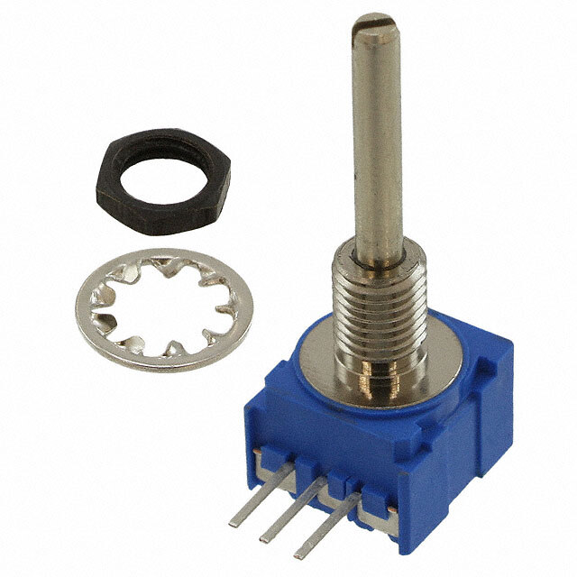
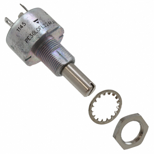
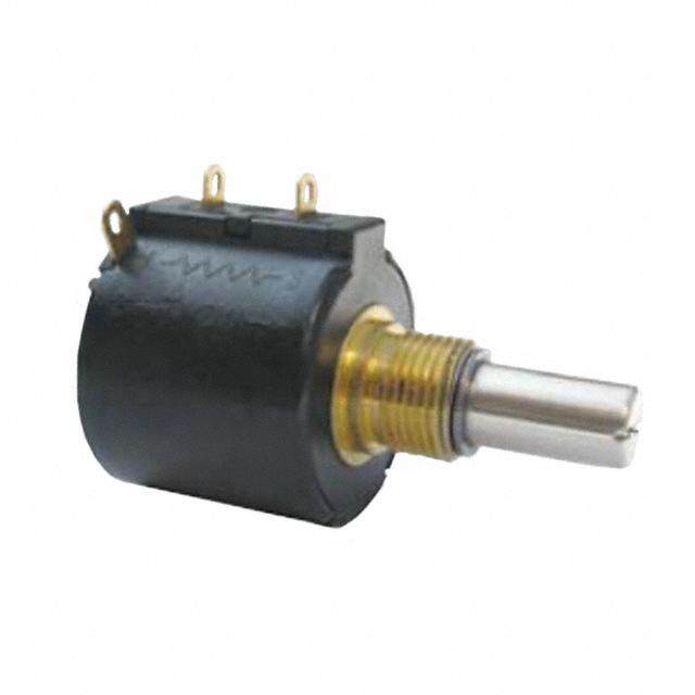
51SAD-U25-A15L产品简介:
ICGOO电子元器件商城为您提供51SAD-U25-A15L由Bourns设计生产,在icgoo商城现货销售,并且可以通过原厂、代理商等渠道进行代购。 51SAD-U25-A15L价格参考¥39.22-¥81.23。Bourns51SAD-U25-A15L封装/规格:旋转式电位计,变阻器, 10k Ohm 1 Gang 线性 面板安装 Potentiometer 无 1 Turn 金属陶瓷 1W PC 引脚。您可以下载51SAD-U25-A15L参考资料、Datasheet数据手册功能说明书,资料中有51SAD-U25-A15L 详细功能的应用电路图电压和使用方法及教程。
Bourns Inc.的51SAD-U25-A15L是一款旋转式电位计(可变电阻器),常用于需要手动调节电阻值的电子设备中。该型号属于工业级电位计,具有较高的可靠性和耐用性,适用于多种工业和电子控制场景。

典型应用场景包括:

1. 工业控制设备:如PLC(可编程逻辑控制器)、工业自动化系统中,用于调节电压、电流或控制参数。
2. 测试与测量仪器:用于校准设备、信号发生器或示波器等,作为手动调节灵敏度或范围的部件。
3. 电源管理系统:用于调节输出电压或电流,如直流电源、稳压器等。
4. 音频设备:如专业音响设备、混音台、功放中,用于音量或均衡调节。
5. 医疗设备:用于调节设备参数,如监护仪、治疗设备中的设定调节。
6. 通信设备:用于调节信号强度、频率等参数,如收发器、调制解调器等。

该电位计具有旋转式调节方式,调节范围广,适合需要精细调节的场合。其机械寿命长、稳定性好,适合在较为严苛的工业环境中使用。
| 参数 | 数值 |
| 产品目录 | |
| 描述 | POT 10K OHM 1/2" SQ 1W CERMET电位计 1/2" PANL CONTRL 10K SQ Sealed 1Turn |
| 产品分类 | 旋转式电位计 - 线性电位器、微调器和变阻器 |
| 品牌 | Bourns |
| 产品手册 | |
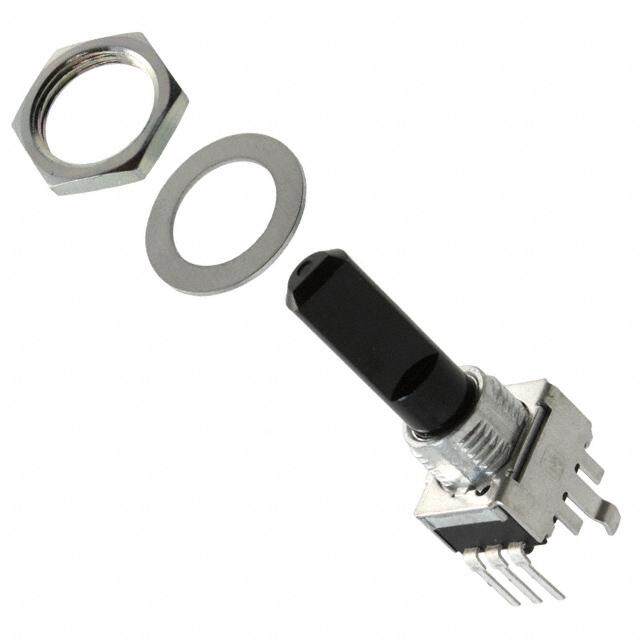
| 产品图片 |
|
| rohs | RoHS 合规性豁免无铅 / 符合限制有害物质指令(RoHS)规范要求 |
| 产品系列 | 电位计,Bourns 51SAD-U25-A15L51 |
| 数据手册 | |
| 产品型号 | 51SAD-U25-A15L |
| PCN其它 | |
| PCN设计/规格 | |
| RoHS指令信息 | |
| 产品 | Musical Syst Potentiometer |
| 产品种类 | 电位计 |
| 元件类型 | Cermet |
| 其它名称 | 51SADU25A15L |
| 功率(W) | 1W |
| 功率额定值 | 1 W |
| 包装 | 散装 |
| 商标 | Bourns |
| 圈数 | 单路 |
| 安装类型 | 通孔 |
| 安装风格 | Panel |
| 容差 | 10 % |
| 封装 | Bulk |
| 尺寸-本体 | 矩形 - 0.521" x 0.492" 表面 x 0.350" 长 (13.25mm x 12.50mm x 8.89mm) |
| 工厂包装数量 | 45 |
| 旋转 | 290° |
| 标准包装 | 45 |
| 温度系数 | ±150ppm/°C |
| 电阻 | 10 kOhms |
| 电阻(Ω) | 10k |
| 电阻材料 | 金属陶瓷 |
| 端子类型 | PCB 引脚 |
| 端接类型 | Pin |
| 系列 | 51 |
| 致动器直径 | 0.118"(3.00mm) |
| 致动器类型 | 开槽轴 |
| 致动器长度 | 0.984"(25.00mm) |
| 调节类型 | 侧面调节 |
| 转数 | 1 |
| 轴直径 | 3 mm |
| 轴类型 | Slotted |
| 轴长度 | 25 mm |
| 锥度 | Linear |


- 商务部:美国ITC正式对集成电路等产品启动337调查
- 曝三星4nm工艺存在良率问题 高通将骁龙8 Gen1或转产台积电
- 太阳诱电将投资9.5亿元在常州建新厂生产MLCC 预计2023年完工
- 英特尔发布欧洲新工厂建设计划 深化IDM 2.0 战略
- 台积电先进制程称霸业界 有大客户加持明年业绩稳了
- 达到5530亿美元!SIA预计今年全球半导体销售额将创下新高
- 英特尔拟将自动驾驶子公司Mobileye上市 估值或超500亿美元
- 三星加码芯片和SET,合并消费电子和移动部门,撤换高东真等 CEO
- 三星电子宣布重大人事变动 还合并消费电子和移动部门
- 海关总署:前11个月进口集成电路产品价值2.52万亿元 增长14.8%


PDF Datasheet 数据手册内容提取
Features NT MPLIA ■ RoHS compliant* O HS C ■ Conductive plastic or cermet *Ro ■ Linear and audio tapers ■ PC board and bushing mount ■ Gangable ■ Metal bushing and shaft ■ Sealed for board washing 51/53 - Sealed 1/2 ” (12.5 mm) Square Control Electrical Characteristics1 Conductive Plastic Cermet Standard Resistance Range Linear ...................................................................................................1 K ohms to 1 megohm .........................150 ohms to 1 megohm Audio ....................................................................................................1 K ohms to 1 megohm .........................1 K ohms to 1 megohm Total Resistance Tolerance Linear Tapers ........................................................................................±10 % or ±20 % ....................................±10 % or ±5 % Audio Tapers ........................................................................................±10 % or ±20 % ....................................±10 % Independent Linearity .................................................................................±5 % ......................................................±5 % Absolute Minimum Resistance ...................................................................2 ohms maximum ..................................2 ohms maximum Eff ective Electrical Angle ............................................................................270 ° ±5 ° ..............................................270 ° ±5 ° Contact Resistance Variation .....................................................................2 % ........................................................2 % Dielectric Withstanding Voltage (MIL-STD-202 – Method 301) Sea Level ..............................................................................................1,500 VAC minimum ..............................1,500 VAC minimum 70,000 ..................................................................................................500 VAC minimum .................................500 VAC minimum Insulation Resistance .................................................................................1,000 megohms minimum .....................1,000 megohms minimum Power Rating At 70 °C (Derate To 0 At 125 °C) (Voltage Limited By Power Dissipation or 350 VAC, Whichever Is Less) Linear Tapers ........................................................................................0.5 watt ..................................................1.0 watt Audio Tapers ........................................................................................0.25 watt ................................................0.5 watt Theoretical Resolution ................................................................................Essentially infi nite ..................................Essentially infi nite Environmental Characteristics1 Operating Temperature Range ...................................................................+1 °C to +125 °C ...................................+1 °C to +125 °C Storage Temperature Range ......................................................................-55 °C to +125 °C ..................................-55 °C to +125 °C Temperature Coeffi cient Over Storage Temperature Range ......................±1,000 ppm/°C ......................................±150 ppm/°C Vibration (Single Section) ...........................................................................15 G .......................................................15 G Total Resistance Shift ...........................................................................±2 % maximum .....................................±2 % maximum Voltage Ratio Shift ................................................................................±5 % maximum .....................................±5 % maximum Shock (Single Section) ...............................................................................30 G .......................................................30 G Total Resistance Shift ...........................................................................+2 % maximum .....................................±2 % maximum Voltage Ratio Shift ................................................................................±5 % maximum .....................................±5 % maximum Load Life .....................................................................................................1,000 hours ...........................................1,000 hours Total Resistance Shift ...........................................................................±10 % TRS maximum ...........................±5 % TRS maximum Rotational Life (No Load) ............................................................................50,000 cycles ........................................25,000 cycles Total Resistance Shift ...........................................................................±10 % TRS maximum ...........................±10 % TRS maximum Contact Resistance Variation @ 25,000 Cycles ...................................±2 % ......................................................±4 % Moisture Resistance (MIL-STD-202, Method 103, Condition B) Total Resistance Shift ...........................................................................±10 % TRS ............................................±5 % TRS IP Rating Entire Unit .............................................................................................IP64 .......................................................IP64 Shaft/Bushing.......................................................................................IP65 .......................................................IP65 Mechanical Characteristics Stop Strength ...............................................................................................................................................................................................56 N-cm (5 lb.-in.) Mechanical Angle ......................................................................................................................................................................................................290 ° ±5 ° Torque Starting (Dual Sections) ..............................................................................................................................................+0.35 N-cm (+0.5 oz.-in.) maximum Running (Single Section) .............................................................................................................................................0.15 to 1.4 N-cm (0.2 to 2.0 oz.-in.) Running (Dual Section) ................................................................................................................................................0.35 to 1.8 N-cm (0.5 to 2.5 oz.-in.) Detent (Single Section) ...................................................................................................................................................1.94 N-cm (2.75 oz.-in.) minimum Mounting (Torque on Bushing) ..........................................................................................................................1.7 to 2.0 N-m (15 to 18 lb.-in.) maximum Weight (Single Section)..............................................................................................................................................................................................5.5 grams (Additional Section) .............................................................................................................................................................................................3.0 grams Terminals ...................................................................................................................................................................................................PC pin or solder lug Soldering Condition ..................................................................Recommended hand soldering using Sn95/Ag5 no clean solder, 0.025 ” wire diameter. Maximum temperature 399 °C (750 °F) for 3 seconds. No wash process to be used with no clean fl ux. Part can be wave soldered at 260 °C (500 °F) for 5 seconds, no wash process with no clean fl ux. Marking ..................................................................................................................Manufacturer’s trademark, part number, resistance value and date code. Ganging (Multiple Section Potentiometer) ............................................................................................................................................2 sections maximum** Hardware ...........................................One lockwasher and one mounting nut is shipped with each potentiometer, except where noted in the part number. 1At room ambient: +25 °C nominal and 50 % relative humidity nominal, except as noted. ** Additional sections available on special request with higher minimum order quantities. *RoHS Directive 2002/95/EC Jan. 27, 2003 including annex and RoHS Recast 2011/65/EU June 8, 2011. Specifi cations are subject to change without notice. The device characteristics and parameters in this data sheet can and do vary in different applications and actual device performance may vary over time. Users should verify actual device performance in their specifi c applications.
51/53 - Sealed 1/2 ” (12.5 mm) Square Control Product Dimensions PACKAGE DIMENSIONS 7.62 FMS MODEL 51 (.300) 5.08 16.51 ± 0.25 6.35 (.200) (.650 ± .010) 8.89 ± 0.18 (.250) 1.32 (.350 ± .007) 12.5 (.052) (.492) "L"( ..06245) (1.413.020) DIA. (6.2.2456) T2Y.5P4. 7.00 (.100) (.275) CLOF POT 0.74 (.029) 1.27 0.30 (.050) 1.02 7.62 ± 0.30 (.50.10188 ±) 0.30 3 X (. 0.6266 ±± ..00502) (.62.6600 ±± 0.0.3185) 4 DPILAC.S. 6(. 0DP4ILA0C.)S. (.300 ± .012) (.200 ± .012) 2.54 (.100) (DOUBLE MODULE FRONT AND REAR BRACKET SHOWN) 2.54 (.100) (SINGLE AND DUAL MODULE SHOWN) 2.54 (.100) TERMINAL SPACING PACKAGE DIMENSIONS PCB MOUNTING BRACKET SOLDER LUG TERMINALS MODEL 53 12.5 .64 (.492) "L"( .025) 11.00 6.25 (.432) DIA. (.246) 7.00 2.40 3 2 1 5.0 ± 0.51 (.275) (.094) (.197 ± .020) 0.74 (.029) 1.32 ± 0.25 0.90 1.80 (.052 ± .010) (.036) (.071) (0.0.9316 ±± ..005012) (5.2.0080 ±± 0.0.3102) 2 X( .0.4116 ±± ..500.50028) (5.2.00(.8062).6600 ±± 0.0.3185) 2 X(4.1.7805) 6.35 ± .25 7.62 ± 0.30 (.200) (.250 ± .010) (.300 ± .012) ELECTRICAL SCHEMATIC 2.54 2 X (.100) CCW 1 3 CW 2 ANTI-ROTATION LUG SHAFT FLAT SUGGESTED PANEL LAYOUT (Style "A" Shown) 5.70 ORIENTATION 0.41 (.224) 6.20 0.80 ± 0.30 (.016) (.244) (.031 ± .012) 1.52 (.060) 132 ° ± 5 ° (2.0.2869)DIA. CCW END BUSHING DIAMETER TOLERANCE +0.25 ( +.010) .25 FOR TOLERANCES SHOWN: .XX = ± (.010) .XXX = ± .13 (.005) SHAFT DIMENSIONS ± .80 (1/32) MM DIMENSIONS: (INCHES) Specifi cations are subject to change without notice. The device characteristics and parameters in this data sheet can and do vary in different applications and actual device performance may vary over time. Users should verify actual device performance in their specifi c applications.
51/53 - Sealed 1/2 ” (12.5 mm) Square Control Shaft/Bushing Styles How To Order 9.53 A Style Bushing (.375) 1.60 ± 0.25 STD. LENGTH ‘L’ 51 A A D - B 28 - A 15 / A15 L (.063 ± .010) OPT. .500 (12.7) .625 (15.88) Part number for multiple .750 (19.05) section potentiometers 1.194 ± 0.10 .875 (22.23) must have a taper (.047 ± .004) OPT. 1.000 (25.4) and resistance value 3/8-32UNEF-2A for each section. 6.35 9.53 SHAFT BUSHING (.250) (.375) RoHS IDENTIFIER L Compliant 6.35 C Style Bushing (.250) 0.79 ± 0.25 OPT. STD. LENGTH ‘L’ (.031 ± .010) .375 (9.53) ELEMENT TAPER RESISTANCE TYPE/TOLERANCE (CODE) .500 (12.7) Code Description VALUE IN OHMS .625 (15.88) MOUNTING BRACKET/ 1/4-32UNEF-2A (0.0.3791 ±± .00.0140 ) OPT. ..785705 ((1292..0253)) CodAeNDTIe-RscOrTipAtTioIOnN LUG ((AH )) L Liinneeaarr CCeerrmmeet t± ±51 %0 % (((200876))) ——— 122550000 (((131405))) ——— 711.505 KKK 3.18 SHAFT 6.35 BUSHING 1.000 (25.4) A AR Lug 90 °CW (08) — 500 (16) — 20 K (.125) (.250) D No AR Lug or Bracket (09) — 750 (17) — 25 K L Front Bracket (10) — 1 K (18) — 50 K (9.3.5735) 1M.5A2X .± F 0L.A2T5 LEONPGTT. H 1(.652.858) A SFtlaytlete Bdu Sshhainftg - MN RFreoanrt Barnadc kReetar Bracket (((211912))) ——— 122. .5K5 KK (((122930))) ——— 751500 00K KK (.060 ± .010) STD. LENGTH ‘L’ (13) — 5 K (25) — 1 M .625 (15.88) (B) Linear C-P ±20 % (10) — 1 K (18) — 50 K .750 (19.05) # SECTIONS/DETENTS (E) Linear C-P ±10 % (12) — 2.5 K (20) — 100 K .875 (22.23) Code Description (13) — 5 K (22) — 250 K 3/8-32UNEF-2A (.52.1469 ±± .00.0150) OPT. 1.000 (25.4) AB SDionugbllee NNoo DDeetteenntt ((1165)) —— 2100 KK ((2235)) —— 510 M0 K (.62.3505) SHAFT (.93.7535 ) BUSHING EF SDionugblele w w/C/Ceennteter rD Deetetenntt (C ) C±1W0 A%u dio Cermet (((111720))) ——— 2215 .5K K K ((1208)) —— 15000 K K (F) CCW Audio Cermet (13) — 5 K (23) — 500 K ±10 % (15) — 10 K (25) — 1 M (.381.05) (.10.6502 ±± .00.1205) S S.S6T3tDy0. l LeE NBG(u1Ts6Hh. 0‘iL)n’g CBoUdSeHIDNeGs cCrOipNtiFoInGURATION ((DS )) CCWW AAuuddiioo CC--PP ±±1200 %% (((111720))) ——— 2215. 5K K K ((2108)) —— 15000 K K .866 (22.0) A 3/8 ” D x 3/8 ” L (13) — 5 K (22) — 250 K 0.79 ± 0.10 .984 (25.0) C 1/4 ” D x 1/4 ” L (15) — 10 K (23) — 500 K (.031 ± .004) R 10 mm D x 9.5 mm L (17) — 25 K (25) — 1 M M6 X .075-6g S 6 mm D x 8 mm L (G) CCW Audio C-P (10) — 1 K (18) — 50 K 3.0 SHAFT 6.0 BUSHING U 7 mm D x 8 mm L ±20 % (12) — 2.5 K (20) — 100 K (.118) (2.36) (T) CCW Audio C-P (13) — 5 K (22) — 250 K ±10 % (15) — 10 K (23) — 500 K (17) — 25 K (25) — 1 M MODEL (Y) CW Dual Audio (10) — 1 K (18) — 50 K 8.0 1.52 ± 0.25 U Style Bushing Code Description Taper C-P ±20 % (12) — 2.5 K (20) — 100 K (.315) (.060 ± .010) STD. LENGTH ‘L’ 51 PC Pins (.100 ” centers) (13) — 5 K (22) — 250 K .630 (16.0) 53 Solder Lugs (15) — 10 K (23) — 500 K .866 (22.0) (17) — 25 K (25) — 1 M 0.79 ± 0.10 .984 (25.0) (.031 ± .004) M7 X .075-6g 4.0 7.0 (.157)SHAFT (2.75)BUSHING AVAILABLE ONLY IN SHAFT AVAILABLE SHAFT TYPE BUSHINGS LENGTHS LENGTH ONLY IN Code Description Code Description (FMS) BUSHING (.397.54) (.10.7810 ±± .00.2105) RS .S6T3tDy0. lLeE NBG(u1Ts6H.h 0‘iL)n’g BCE SSSiiinnngggllleee FSSlalloottttetteeddd 1 11/4//48 ” D””DD ACA 122,01,622,442,,022,882,43,228 C112o260d e D315///e828s ”””c ription CAAoC,, dCCe .866 (22.0) R Single Slotted 6 mmD R 16,22,25 24 3/4 ” A, C .984 (25.0) T Single Slotted 4 mmD U 16,22,25 28 7/8 ” A, C 1.00 ± 0.10 U Single Slotted 3 mmD S 16,22,25 32 1 ” A, C (.039 ± .004) Metric M10 X 0.75-6g 16 16 mm R, S, U 6.0 10.0 22 22 mm R, S, U (.236)SHAFT (.394) BUSHING 25 25 mm R, S, U Boldface features are Bourns standard options. All others are available with higher MM DIMENSIONS: minimum order quantities. (INCHES) REV. 12/14 Specifi cations are subject to change without notice. The device characteristics and parameters in this data sheet can and do vary in different applications and actual device performance may vary over time. Users should verify actual device performance in their specifi c applications.