ICGOO在线商城 > 电位计,可变电阻器 > 旋转式电位计,变阻器 > 53C3500K
 Datasheet下载
- 型号: 53C3500K
- 制造商: Honeywell Solid State Electronics
- 库位|库存: xxxx|xxxx
- 要求:
| 数量阶梯 | 香港交货 | 国内含税 |
| +xxxx | $xxxx | ¥xxxx |
查看当月历史价格
查看今年历史价格
53C3500K产品简介:
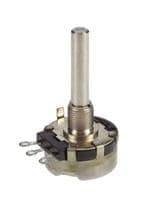
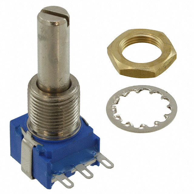
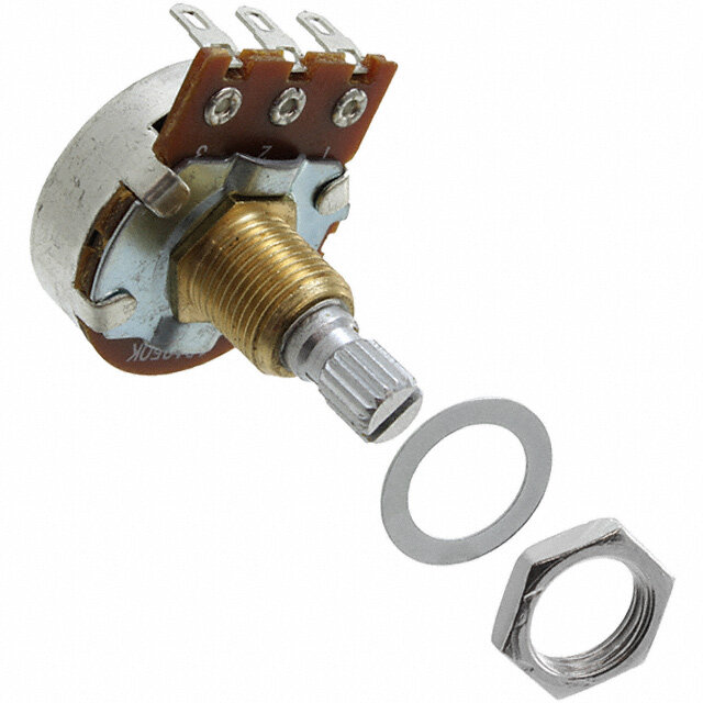
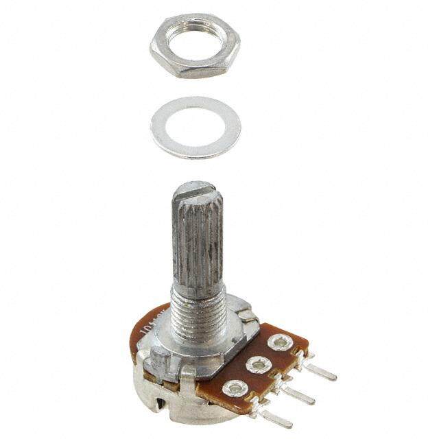
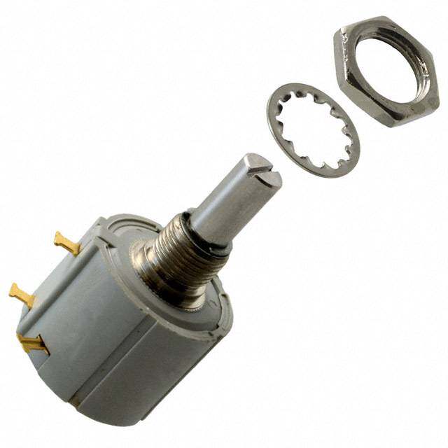
ICGOO电子元器件商城为您提供53C3500K由Honeywell Solid State Electronics设计生产,在icgoo商城现货销售,并且可以通过原厂、代理商等渠道进行代购。 53C3500K价格参考¥68.34-¥78.22。Honeywell Solid State Electronics53C3500K封装/规格:旋转式电位计,变阻器, 500k Ohm 1 Gang Linear Panel Mount Potentiometer None 1 Turn Conductive Plastic 2W Solder Lug。您可以下载53C3500K参考资料、Datasheet数据手册功能说明书,资料中有53C3500K 详细功能的应用电路图电压和使用方法及教程。
Honeywell Sensing and Productivity Solutions 旗下的型号为 53C3500K 的旋转式电位计(变阻器),主要应用于需要精确控制电阻变化的工业和设备控制系统中。该产品具有良好的稳定性和耐用性,适用于多种调节与传感场景。

典型应用场景包括:

1. 工业设备控制:用于调节速度、温度或压力等参数,如在机床、输送带或自动化装配线中作为手动调节元件。
2. 测试与测量仪器:用于校准设备或调节灵敏度,确保测量精度。
3. 电源管理系统:用于调节输出电压或电流,常见于电源供应器或电池管理系统中。
4. 暖通空调系统(HVAC):用于调节风速、温度设定或风扇控制。
5. 医疗设备:用于调节设备参数,如输液泵、监测仪等对精度要求较高的场合。
6. 安防设备:如摄像头云台控制或报警系统的灵敏度调节。

该电位计具备旋转调节方式,阻值范围为 0 至 3500KΩ,适合需要大范围电阻调节的应用环境。其结构坚固,适合在中等恶劣环境中使用。
| 参数 | 数值 |
| 产品目录 | |
| 描述 | POT 500K OHM 2W COND PLASTIC电位计 500K Ohm 10% 2W 6.35mm |
| 产品分类 | 旋转式电位计 - 线性电位器、微调器和变阻器 |
| 品牌 | Honeywell |
| 产品手册 | http://sensing.honeywell.com/product%20page?pr_id=26938 |
| 产品图片 |
|
| rohs | 否无铅 / 符合限制有害物质指令(RoHS)规范要求 |
| 产品系列 | 电位计,Honeywell 53C3500K53C |
| mouser_ship_limit | 该产品可能需要其他文件才能进口到中国。 |
| 数据手册 | |
| 产品型号 | 53C3500K |
| 产品 | Potentiometer |
| 产品种类 | 电位计 |
| 元件类型 | Conductive Plastic |
| 其它名称 | 53C3-500KZ |
| 功率(W) | 2W |
| 功率额定值 | 2 W |
| 包装 | 散装 |
| 商标 | Honeywell |
| 圈数 | 单路 |
| 安装类型 | 面板安装 |
| 安装风格 | Panel |
| 容差 | 10 % |
| 尺寸-本体 | 圆形 - 1.094" 直径 x 0.563" 长(27.78mm x 14.29mm) |
| 工作温度范围 | - 40 C to + 120 C |
| 工厂包装数量 | 100 |
| 旋转 | 312° |
| 标准包装 | 100 |
| 温度系数 | - |
| 电阻 | 500 kOhms |
| 电阻(Ω) | 500k |
| 电阻材料 | 导电塑料 |
| 端子类型 | 焊片 |
| 端接类型 | Solder Lug |
| 系列 | 53 |
| 致动器直径 | 0.250"(6.35mm) |
| 致动器类型 | 开槽轴 |
| 致动器长度 | 0.875"(22.23mm) |
| 调节类型 | 侧面调节 |
| 轴直径 | 6.35 mm |
| 轴类型 | Slotted |
| 轴长度 | 22.23 mm |
| 锥度 | Linear |
| 零件号别名 | RV4NAYSD504A |


- 商务部:美国ITC正式对集成电路等产品启动337调查
- 曝三星4nm工艺存在良率问题 高通将骁龙8 Gen1或转产台积电
- 太阳诱电将投资9.5亿元在常州建新厂生产MLCC 预计2023年完工
- 英特尔发布欧洲新工厂建设计划 深化IDM 2.0 战略
- 台积电先进制程称霸业界 有大客户加持明年业绩稳了
- 达到5530亿美元!SIA预计今年全球半导体销售额将创下新高
- 英特尔拟将自动驾驶子公司Mobileye上市 估值或超500亿美元
- 三星加码芯片和SET,合并消费电子和移动部门,撤换高东真等 CEO
- 三星电子宣布重大人事变动 还合并消费电子和移动部门
- 海关总署:前11个月进口集成电路产品价值2.52万亿元 增长14.8%

PDF Datasheet 数据手册内容提取
2 W Conductive Plastic Potentiometers 380 Series, RV4 Series, 485 Series, 53C Series, 385 Series Datasheet
Conductive Plastic Potentiometers Potentiometers convert rotary motion into a change of resistance, supplying a smooth transition of voltage or current levels. The resulting voltage output may be used to control position transducers in a wide variety of potential applications. The five series listed below are all 2 W plastic potentiometers and are available in resistances from 100 Ohm to 5 MOhm, inclusive. Available tapers include linear, log, and antilog to meet a wide range of application requirements. These single turn devices have a 6,35 mm [0.250 in] diameter shaft that is available in a range of lengths. Most shafts are nickel-plated brass. Most configurations have a standard 3/8-32 NEF-2A bushing; a high torque version is also available. Termination types are solder lug (with or without a center tap), PC pin or fast-on, all are solder-dipped. Custom designs are available upon request. • 380 Series: 2 W conductive plastic potentiometer offering low contact resistance variation and a long rotational life • RV4 Series: Military version of the 380 Series; meets MIL-R-94 requirements (non RoHS compliant) • 485 Series: Custom version of the 380 Series • 53C Series: Cost-effective version of the 380 Series • 385 Series: Custom version of the 53C Series Key Features and Benefits , Table of Contents • Cost-effective: Supplies good performance at a reasonable price General Specifications . . . . . . . . . . . . . . . . . 3-6 • Wide range of resistance values (100 Ohm to 5 MOhm, inclusive): Promotes flexibility in the applications General Configuration Guide . . . . . . . . . . . . . . 7 • Wide variety of tapers: Creates flexibility in output signal 380 Series: profile, allowing use in a wide variety of applications Specific Configurations . . . . . . . . . . . . . . . . . 8 Order Guides . . . . . . . . . . . . . . . . . . . . . . 9-15 Potential Applications RV4 Series: INDUSTRIAL/COMMERCIAL Specific Configurations . . . . . . . . . . . . . . . . 16 • Audio and visual equipment (e.g., musical instruments, Order Guides . . . . . . . . . . . . . . . . . . . . . . 17-18 sound mixers, projectors, amplifiers) 485 Series: • Foot pedal controls (e.g., guitars, sewing machines, Specific Configurations . . . . . . . . . . . . . 19-21 woodworking equipment) • Machine controls (e.g., joysticks) Order Guides . . . . . . . . . . . . . . . . . . . . . 22-31 • Welding equipment (e.g., MIG wire feed, foot pedal controls, 53C Series: adjustment knobs) Specific Configurations . . . . . . . . . . . . . . . . 32 TRANSPORTATION Order Guides . . . . . . . . . . . . . . . . . . . . . 33-37 • Foot pedal controls (e.g., golf carts) 385 Series: • Gear shifter, joystick, and throttle position (e.g., construction/ Specific Configurations . . . . . . . . . . . . . 38-39 agricultural vehicles) Order Guides . . . . . . . . . . . . . . . . . . . . . 40-46 Additional Information . . . . . . . . . . . . back page COST-EFFECTIVE • MIL-R-94 • CUSTOMIZATION AVAILABLE 2 Sensing and Productivity Solutions
General Specifications Table 1. Electrical Specifications Characteristic 380 Series RV4 Series 485 Series 53C Series 385 Series Maximum working voltage: linear tapers 500 Vdc log, reverse log tapers 350 Vdc Dielectric strength 1000 Vac for 60 s at 1 mPa [atm], 450 Vac for 60 s at 11,5 kPa [3.4 inHg] Power rating 2 W at 70 °C [158 °F], derated to 120 °C [248 °F] Taper See Order Guides under each series CRV1: linear tapers 3% max. total resistance log, reverse log tapers 3% max. total resistance Resistance 100 Ohm to 5 MOhm, inclusive. See individual Order Guides under each series. Resistance tolerance See Order Guides under each series. End resistance See Order Guides under each series. Linearity ±5% Electrical rotation See Order Guides under each series. 1Contact resistance variation is the maximum momentary change in contact resistance that occurs when the wiper is moved from one location to another location. The larger this change, the more difficult it is to set the trimmer potentiometer and the more unstable the long term setting will be. Table 2. Mechanical Specifications Characteristic 380 Series RV4 Series 485 Series 53C Series 385 Series Shaft: material nickel-plated brass1 diameter 6,35 mm [0.250 in] Retaining ring nickel-plated nickel-plated brass nickel-plated brass material beryllium copper Bushing: material nickel-plated brass thread 3/8-32 NEF-2A Termination base thermoset material brass; solder brass; solder brass; solder brass; solder (SAC305) dip or Terminal material (SAC305) dip or (SAC305) dip finish (SAC305) dip finish tin-lead finish tin-lead finish Housing material stainless steel Base material thermoset plastic Mounting hardware material: jam nut nickel-plated brass mounting nut nickel-plated brass lock washer nickel-plated brass phospher bronze1 o-ring silicone rubber Operating torque See Order Guides under each series. Stop torque See Order Guides under each series. Weight (approx.) 32.7 g [0.072 lb] 1Unless otherwise specified on the Order Guides under each series. Sensing and Productivity Solutions 3
General Specifications Table 3. Environmental Specifcations Characteristic 380 Series RV4 Series 485 Series 53C Series 385 Series Operating temperature -55 °C to 120 °C [-67 °F to 248 °F] Rotational life tested to 25,000 cycles Table 4. Maximum Percent Temporary Resistance from 25 °C [77 °F] Temperature Nominal Resistance -55 °C -40 °C 0 °C 25 °C 55 °C 85 °C 120 °C [-67 °F] [-40 °F] [32 °F] [77 °F] [131 °F] [185 °F] [248 °F] 100 Ohm ±5.0 ±4.0 ±1.5 0 ±1.5 ±2.0 ±3.5 10 kOhm +7.0 +5.5 +2.0 0 ±1.5 ±2.5 ±5.5 100 kOhm +8.0 +6.0 +2.5 0 ±2.0 ±3.5 ±6.0 1 MOhm +10.0 +8.0 +3.0 0 ±2.5 ±4.0 ±7.5 Figure 1. Electrical Taper Diagrams (For reference only.) Log (Z) Reverse Log (RZ) Linear: 2.5% to 97.5% (S-1) 100 100 100 90 90 90 80 80 80 Total Resistance (%) 3456700000 Total Resistance (%) 3456700000 Total Resistance (%) 3456700000 20 20 20 10 10 10 0 0 0 0 10 20 30 40 50 60 70 80 90 100 0 10 20 30 40 50 60 70 80 90 100 0 10 20 30 40 50 60 70 80 90 100 Angular Rotation, Clockwise Left to Right (%) Angular Rotation, Clockwise Left to Right (%) Angular Rotation, Clockwise Left to Right (%) Linear: 5% to 95% (S-2) Linear: 7.5% to 92.5% (S-3) Linear: 10% to 90% (S-4) 100 100 100 90 90 90 80 80 80 Total Resistance (%) 3456700000 Total Resistance (%) 3456700000 Total Resistance (%) 3456700000 20 20 20 10 10 10 0 0 0 0 10 20 30 40 50 60 70 80 90 100 0 10 20 30 40 50 60 70 80 90 100 0 10 20 30 40 50 60 70 80 90 100 Angular Rotation, Clockwise Left to Right (%) Angular Rotation, Clockwise Left to Right (%) Angular Rotation, Clockwise Left to Right (%) 4 Sensing and Productivity Solutions
General Specifications Figure 1. Electrical Taper Diagrams (continued) Linear: 15% to 95% (S-5) Linear: 25% to 75% (S-6) Linear: 35% to 65% (S-7) 100 100 100 90 90 90 80 80 80 Total Resistance (%) 3456700000 Total Resistance (%) 3456700000 Total Resistance (%) 3456700000 20 20 20 10 10 10 0 0 0 0 10 20 30 40 50 60 70 80 90 100 0 10 20 30 40 50 60 70 80 90 100 0 10 20 30 40 50 60 70 80 90 100 Angular Rotation, Clockwise Left to Right (%) Angular Rotation, Clockwise Left to Right (%) Angular Rotation, Clockwise Left to Right (%) Linear: 37.5% to 82.5% (S-8) Linear: 42.5% to 57.5% (S-9) Linear: 45% to 55% (S-10) 100 100 100 90 90 90 80 80 80 Resistance (%) 567000 Resistance (%) 567000 Resistance (%) 567000 Total 40 Total 40 Total 40 30 30 30 20 20 20 10 10 10 0 0 0 0 10 20 30 40 50 60 70 80 90 100 0 10 20 30 40 50 60 70 80 90 100 0 10 20 30 40 50 60 70 80 90 100 Angular Rotation, Clockwise Left to Right (%) Angular Rotation, Clockwise Left to Right (%) Angular Rotation, Clockwise Left to Right (%) Linear: 5% to 50%; 50% to 90% (S-11) Linear: 10% to 40%; 57.5% to 82.5% (S-12) Linear: 10% to 45%; 55% to 90% (S-13) 100 100 100 90 90 90 80 80 80 Resistance (%) 567000 Resistance (%) 567000 Resistance (%) 567000 Total 40 Total 40 Total 40 30 30 30 20 20 20 10 10 10 0 0 0 0 10 20 30 40 50 60 70 80 90 100 0 10 20 30 40 50 60 70 80 90 100 0 10 20 30 40 50 60 70 80 90 100 Angular Rotation, Clockwise Left to Right (%) Angular Rotation, Clockwise Left to Right (%) Angular Rotation, Clockwise Left to Right (%) Linear: 35% to 45%; 55% to 65% (S-14) Linear: 45% to 47.5%; 47.5% to 52.5%; Linear: 5% to 40%; 45% to 52.5%; 52.5% to 55% (S-15) 60% to 95% (S-16) 100 100 100 90 90 90 80 80 80 Resistance (%) 567000 Resistance (%) 567000 Resistance (%) 567000 Total 40 Total 40 Total 40 30 30 30 20 20 20 10 10 10 0 0 0 0 10 20 30 40 50 60 70 80 90 100 0 10 20 30 40 50 60 70 80 90 100 0 10 20 30 40 50 60 70 80 90 100 Angular Rotation, Clockwise Left to Right (%) Angular Rotation, Clockwise Left to Right (%) Angular Rotation, Clockwise Left to Right (%) Sensing and Productivity Solutions 5
General Specifications Figure 2. Power Derating Curve 100 90 80 70 %) er (60 w o50 P d e40 at R 30 20 10 0 0 10 20 30 40 50 60 70 80 90 100 110 120 Temperature (°C) Figure 3. Mounting Hardware Jam Nut Mounting Nut Lock Washer O-Ring 7,94 mm [5/16 in] across flats 1/4 x 32 thread 10,32 mm [5/16 in] outside 6,35 mm [0.25 in] outside diameter 3,97 mm [5/32 in] thick 7,94 mm [5/16 in] across flats diameter 0,64 mm [0.025 in] thick 1,78 mm [0.070 in] thick 6 Sensing and Productivity Solutions
General Configuration Guide Figure 4. General Configuration Guide This figure shows possible configurations. Not all combinations may be available, please contact Honeywell. See the Order Guides for each series on subsequent pages for currently available catalog listings. Resistance Number Signifi- of Zeros Anti-Rotation Product Bushing Shaft Shaft cant that Electrical (AR) Termination Series Type and Length Switch Type Length Digit Follow Taper Locating Pin Type 380 Series, 3/8-32 NEF-2A: None ø3,18 mm [0.125 in]: 9,53 mm [0.325]1 10 Ohm 0 Linear: No locating pins Solder RV4 Series, Standard: F l a t t ed 2.5% to 97.5% lug 485 Series, 6,35 mm [0.25 in] 12,7 mm [0.50 in]1 15 Ohm 1 5% to 95% 53C Series, 15,88 mm [0.625 in] 20 Ohm 2 385 Series 7.5% to 92.5% 2 W 19,05 mm [0.75 in] 25 Ohm 3 One locating pin: 10% to 90% Conductive 22,23 mm [0.875 in] 50 Ohm 4 9 o’ clock Solder Plastic Round 15% to 95% lug with Potentiometers 7,92 mm [0.312 in] 31,75 mm [1.25 in] 5 center tap 25% to 75% 50,8 mm [2.00 in] 35% to 65% 63,5 mm [2.50 in] 3 o’ clock 37.5% to 82.5% Slotted Custom 42.5% to 57.5% PC pin 8,69 mm [0.342 in] 1 bAupsphliiensg sto o 6n,l2y5. mm [0.25 in] 45% to 55% Two locating pins 5% to 50%; 50% to 90% Straight Knurled 10% to 40%; Fast-on 57.5% to 82.5% 9,27 mm [0.365 in] 10% to 45%; Custom 55% to 90% 10% to 45%; Custom Custom 55% to 90% 35% to 45%; 55% to 65%; 9,53 mm [0.375 in] 45% to 57.5%; 52.5% to 55%; General 380 Series, RV4 Series, 485 Series, 5% to 40%; 45% to 52.5%; 53C Series, 385 Series Terminology 60% to 95% 12,7 mm [0.500 in] Log Jam nut Reverse Log Custom Mounting nut High Torque: Mounting 12,7 mm [0.500 in] Lock washer hardware O-ring Custom Locating pin Shaft Bushing Termination Sensing and Productivity Solutions 7
380 Series Specific Configurations Table 5. 380 Series Specific Configurations Shaft Bushing AR Termin- Configuration with Shaft Bushing AR Termin- Configuration with Type Type Pin ation Associated Hardware Type Type Pin ation Associated Hardware 380-A (See Table 380-A on p. 9.) 380-B (See Table 380-B on p. 10.) standard, standard, solder solder flatted 9,53 mm 1 slotted 9,53 mm 2 lug lug [0.375 in] [0.375 in] 380-C (See Table 380-C on p. 10.) 380-D (See Table 380-D on p. 11.) standard, standard, solder flatted 9,53 mm 1 PC pin round 9,53 mm 1 lug [0.375 in] [0.375 in] 380-E (See Table 380-E on p. 12.) 380-F (See Table 380-F on p. 13.) high standard, torque, solder solder slotted 1 slotted 9,53 mm 1 12,7 mm lug lug [0.375 in] [0.500 in] 380-G (See Table 380-G on p. 14.) 380-H (See Table 380-H on p. 14.) standard, standard, solder slotted 9,53 mm 1 slotted 9,53 mm 1 fast-on lug [0.375] in [0.375] in 380-I (See Table 380-I on p. 15.) standard, solder slotted 9,53 mm 2 lug [0.375] in 8 Sensing and Productivity Solutions
380 Series Order Guides Table 380-A Order Guide Electrical Mechanical Dimensions CLaisttailnogg Resistance(Ohm) Resistance Tolerance±%() End Resistanceat CW, Max.(Ohm) End Resistanceat CCW, Max.(Ohm) Effective Electrical Rotation, Typ.(Degree) ±Electrical Rotation, 3(Degree) Taper Mechanical Rotation(Degree) Operating Torque(mN m [in-oz]) Stop Torque(N m [in-lb]) Shaft Seal Flat LengthA(mm [in]) Flat ThicknessB(mm [in]) Shaft LengthC(mm [in]) Bushing LengthD(mm [in]) RoHS Compliant HMaorudnwtainrge 1-4 12 7,95 5,54 19,46 9,53 380000M8629 1 k 10 4 4 274 312 S-4 312 no yes unassembled [7-28] [1.4] [0.313] [0.218] [0.766] [0.375] 1-4 12 7,95 5,54 19,46 9,53 380000M8630 2.5 k 10 4 4 274 312 S-4 312 no yes unassembled [7-28] [1.4] [0.313] [0.218] [0.766] [0.375] 1-4 12 14,30 5,54 25,4 9,53 380000M8643 1 k 10 4 4 274 312 S-4 312 no yes unassembled [7-28] [1.4] [0.563] [0.218] [1.000] [0.375] 1-4 12 7,95 5,54 19,46 9,53 380000M8682 50 k 10 4 4 274 312 S-4 312 no yes unassembled [7-28] [1.4] [0.313] [0.218] [0.766] [0.375] 6 12 7,95 5,54 22,23 9,53 380017M00071,2 500 10 4 4 274 312 S-4 312 yes no unassembled [7-42] [1.4] [0.313] [0.218] [0.875] [0.375] 6 12 7,95 5,54 19,05 9,53 380017M8606 10 k 10 4 4 274 312 S-4 312 yes yes unassembled [7-42] [1.4] [0.313] [0.218] [0.750] [0.375] 6 12 7,95 5,54 19,05 9,53 380017M87681 25 k 10 4 4 274 312 S-4 312 yes yes unassembled [7-42] [1.4] [0.313] [0.218] [0.750] [0.375] 6 12 7,95 5,54 19,05 9,53 380017M95501 5 k 10 4 4 274 312 S-4 312 yes yes unassembled [7-42] [1.4] [0.313] [0.218] [0.750] [0.375] Dimensional Drawings (For reference only: mm [in].) 14,30 C Shown with 50% shaft rotation [0.563] ø27,79 Max. D [1.094] 2,77 A 13,49 [0.109] [0.531] 3,18 B [0.125] Locatipnign ø[06.2,3550] [012.5,8476] 3X 1,57 3/8-32 NEF-2A 22,25 Max. [0.062] Terminal 90° [0.875] base Mounting surface 3X 2,36 0,635 1 3 [0.093] [0.025] 3,18 Min. Left 2 Right 3X 3,15 [0.125] Center [0.124] 3X 1,57 [0.062] 2X 20° 1Supplied with nickel-plated, phosphor bronze lock washer. 2Supplied with two mounting nuts. Sensing and Productivity Solutions 9
380 Series Order Guides Table 380-B Order Guide Electrical Mechanical Dimensions CLaisttailnogg Resistance(Ohm) Resistance Tolerance±%() End Resistanceat CW, Max.(Ohm) End Resistanceat CCW, Max.(Ohm) Effective Electrical Rotation, Typ.(Degree) ±Electrical Rotation, 3(Degree) Taper Mechanical Rotation(Degree) Operating Torque(mN m [in-oz]) Stop Torque(N m [in-lb]) Shaft Seal Flat LengthA(mm [in]) Flat ThicknessB(mm [in]) Shaft LengthC(mm [in]) Bushing LengthD(mm [in]) RoHS Compliant HMaorudnwtainrge 1-6 12 7.95 5,54 19,05 9,53 3800017M8956 10 k 10 4 4 274 312 S-4 312 yes yes unassembled [7-42] [1.4] [0.313] [0.218] [0.750] [0.375] Dimensional Drawings (For reference only: mm [in].) Shown with 50% shaft rotation [014.5,3603] C ø27,79 Max. D [1.094] 2,77 A 13,49 [0.109] [0.531] 2X 3,18 [0.125] B Locatipnign ø[06.,23550] [012.5,8476] 3 X [ 01.,05672] Terminal 3/8-32 NEF-2A [ 02.28,7255] Max. base Mounting surface 90° 3 X [ 02.,03963] [00,.603255] 3,18 Min. L1eft 2 Ri3ght 3X 3,15 [0.125] Center [0.124] 3X 1,57 [0.062] 2X 20° Table 380-C Order Guide Electrical Mechanical Dimensions CLaisttailnogg Resistance(Ohm) Resistance Tolerance±%() End Resistanceat CW, Max.(Ohm) End Resistanceat CCW, Max.(Ohm) Effective Electrical Rotation, Typ.(Degree) ±Electrical Rotation, 3(Degree) Taper Mechanical Rotation(Degree) Operating Torque(mN m [in-oz]) Stop Torque(N m [in-lb]) Shaft Seal Flat LengthA(mm [in]) Flat ThicknessB(mm [in]) Shaft LengthC(mm [in]) Bushing LengthD(mm [in]) RoHS Compliant HMaorudnwtainrge 1-6 12 9,53 5,54 22,23 9,27 380096M9088 10 k 10 4 4 288 312 S-2 312 yes yes none [7-42] [1.4] [0.375] [0.218] [0.875] [0.365] Dimensional Drawings (For reference only: mm [in].) 14,30 C Shown with 50% shaft rotation [0.563] ø27,79 Max. D [1.094] 2,77 A 13,49 [0.109] [0.531] B [03.,11285] Locating 13,87 pin ø6,35 [0.546] [0.250] 32,77 Max. Ter mbainsael 3/8-32 NEF-2A 90° [1.290] Mounting surface 3 X [ 01.,05672] 2 X [ 05.,20080] [00,.603255] 3,18 Min. L1eftCe2nterRi3ght [0.125] 3X 1,02 [0.040] 10 Sensing and Productivity Solutions
380 Series Order Guides Table 380-D Order Guide Electrical Mechanical Dimensions CLaisttailnogg Resistance(Ohm) Resistance Tolerance±%() End Resistanceat CW, Max.(Ohm) End Resistanceat CCW, Max.(Ohm) Effective Electrical Rotation, Typ.(Degree) ±Electrical Rotation, 3(Degree) Taper Mechanical Rotation(Degree) Operating Torque(mN m [in-oz]) Stop Torque(N m [in-lb]) Shaft Seal Shaft LengthA(mm [in]) Bushing LengthB(mm [in]) RoHS Compliant MHaorudnwtianrge 1-4 12 50,8 9,53 380C1100 100 10 4 4 274 312 S-4 312 no yes unassembled [7-28] [1.4] [2.000]) [0.375] 1-4 12 50,8 9,53 380C11000 1000 10 4 4 274 312 S-4 312 no yes unassembled [7-28] [1.4] [2.000] [0.375] 1-4 12 50,8 9,53 380C1100K 100 k 10 4 4 274 312 S-4 312 no yes unassembled [7-28] [1.4] [2.000] [0.375] 1-4 12 50,8 9,53 380C110K 10 k 10 4 4 274 312 S-4 312 no yes unassembled [7-28] [1.4] [2.000] [0.375] 1-4 12 50,8 9,53 380C11MEG 1 M 10 10 10 274 312 S-4 312 no yes unassembled [7-28] [1.4] [2.000] [0.375] 1-4 12 50,8 9,53 380C12000 2 k 10 4 4 274 312 S-4 312 no yes unassembled [7-28] [1.4] [2.000] [0.375] 1-4 12 50,8 9,53 380C120K 20 k 10 4 4 274 312 S-4 312 no no unassembled [7-28] [1.4] [2.000] [0.375] 1-4 12 50,8 9,53 380C1250 250 10 4 4 274 312 S-4 312 no yes unassembled [7-28] [1.4] [2.000] [0.375] 1-4 12 50,8 9,53 380C12500 2.5 k 10 4 4 274 312 S-4 312 no yes unassembled [7-28] [1.4] [2.000] [0.375] 1-4 12 50,8 9,53 380C125K 25 k 10 4 4 274 312 S-4 312 no yes unassembled [7-28] [1.4] [2.000] [0.375] 1-4 12 50,8 9,53 380C135K 35 k 10 4 4 274 312 S-4 312 no yes unassembled [7-28] [1.4] [2.000] [0.375] 1-4 12 50,8 9,53 380C1500 500 10 4 4 274 312 S-4 312 no yes unassembled [7-28] [1.4] [2.000] [0.375] 1-4 12 50,8 9,53 380C15000 5 k 10 4 4 274 312 S-4 312 no yes unassembled [7-28] [1.4] [2.000] [0.375] 1-4 12 50,8 9,53 380C1500K 500 k 10 10 10 274 312 S-4 312 no yes unassembled [7-28] [1.4] [2.000] [0.375] 1-4 12 50,8 9,53 380C150K 50 k 10 4 4 274 312 S-4 312 no yes unassembled [7-28] [1.4] [2.000] [0.375] Dimensional Drawings (For reference only: mm [in].) 14,30 A Shown with 50% shaft rotation [0.563] ø27,79 Max. B [1.094] 2,77 13,49 [0.109] [0.531] 3,18 [0.125] Locatipnign ø[06.2,3550] [012.5,8476] 3X 1,57 22,25 Max. [0.062] Terminal 3/8-32 NEF-2A [0.875] base Mounting surface 3 3 X X [ 302,.,1035963] [00,.603255] [ 03.,11285 M]in. L1eft Ce2nterRi3ght [0.124] 3X 1,57 [0.062] 2X 20° Sensing and Productivity Solutions 11
380 Series Order Guides Table 380-E Order Guide Electrical Mechanical Dimensions CLaisttailnogg Resistance(Ohm) Resistance Tolerance±%() End Resistanceat CW, Max.(Ohm) End Resistanceat CCW, Max.(Ohm) Effective Electrical Rotation, Typ.(Degree) ±Electrical Rotation, 3(Degree) Taper Mechanical Rotation(Degree) Operating Torque(mN m [in-oz]) Stop Torque(N m [in-lb]) Shaft Seal Slot DepthA(mm [in]) Slot WidthB(mm [in]) Shaft LengthC(mm [in]) Bushing LengthD(mm [in]) RoHS Compliant HMaorudnwtainrge 1-4 12 1,60 1,19 15,88 12,7 380C2000 1 k 10 4 4 274 312 S-4 312 no yes unassembled [7-28] [1.4] [0.063] [0.047] [0.625] [0.500] 1-4 12 1,60 1,19 15,88 12,7 380C210K 10 k 10 4 4 274 312 S-4 312 no yes unassembled [7-28 [1.4] [0.063] [0.047] [0.625] [0.500] 1-4 12 1,60 1,19 15,88 12,7 380C225K 25 k 10 4 4 274 312 S-4 312 no yes unassembled [7-28] [1.4] [0.063] [0.047] [0.625] [0.500] 1-4 12 1,60 1,19 15,88 12,7 380C25000 5 k 10 4 4 274 312 S-4 312 no yes unassembled [7-28 [1.4] [0.063] [0.047] [0.625] [0.500] Dimensional Drawings (For reference only: mm [in].) Shown with 50% shaft rotation 14,30 C [0.563] ø27,79 Max. D [1.094] 2,77 A 90° 13,49 [0.109] [0.531] 3,18 [0.125] 3X 1,57Locatipnign ø[06.2,3550] [012.5,8476] [0.062]Terminal 3/8-32 NEF-2A B [ 02.28,7255] Max. 3X 2,36 base Mounting surface [0.093] 0,635 1 3 3X 3,15 [0.025] 3,18 Min. Left Ce2nterRight [0.124] [0.125] 3X 1,57 [0.062] 2X 20° 12 Sensing and Productivity Solutions
380 Series Order Guides Table 380-F Order Guide Electrical Mechanical Dimensions CLaisttailnogg Resistance(Ohm) Resistance Tolerance±%() End Resistanceat CW, Max.(Ohm) End Resistanceat CCW, Max.(Ohm) Effective Electrical Rotation, Typ.(Degree) ±Electrical Rotation, 3(Degree) Taper Mechanical Rotation(Degree) Operating Torque(mN m [in-oz]) Stop Torque(N m [in-lb]) Shaft Seal Slot LengthA(mm [in]) Slot WidthB(mm [in]) Shaft LengthC(mm [in]) Bushing LengthD(mm [in]) RoHS Compliant HMaorudnwtainrge 1-4 12 1,60 1,19 22,23 9,53 380C3100 100 10 4 4 274 312 S-4 312 no yes unassembled [7-28] [1.4] [0.063] [0.047] [0.875] [0.375] 1-4 12 1,60 1,19 22,23 9,53 380C31000 1 k 10 4 4 274 312 S-4 312 no yes unassembled [7-28] [1.4] [0.063] [0.047] [0.875] [0.375] 1-4 12 1,60 1,19 22,23 9,53 380C3100K 100 k 10 4 4 274 312 S-4 312 no yes unassembled [7-28] [1.4] [0.063] [0.047] [0.875] [0.375] 1-4 12 1,60 1,19 22,23 9,53 380C310K 10 k 10 4 4 274 312 S-4 312 no yes unassembled [7-28] [1.4] [0.063] [0.047] [0.875] [0.375] 1-4 12 1,60 1,19 22,23 9,53 380C31MEG 1 M 10 10 10 274 312 S-4 312 no yes unassembled [7-28] [1.4] [0.063] [0.047] [0.875] [0.375] 1-4 12 1,60 1,19 22,23 9,53 380C32000 2 k 10 4 4 274 312 S-4 312 no yes unassembled [7-28] [1.4] [0.063] [0.047] [0.875] [0.375] 1-4 12 1,60 1,19 22,23 9,53 380C3200K 200 k 10 4 4 274 312 S-4 312 no no unassembled [7-28] [1.4] [0.063] [0.047] [0.875] [0.375] 1-4 12 1,60 1,19 22,23 9,53 380C3250 250 10 4 4 274 312 S-4 312 no no unassembled [7-28] [1.4] [0.063] [0.047] [0.875] [0.375] 1-4 12 1,60 1,19 22,23 9,53 380C32500 2.5 k 10 4 4 274 312 S-4 312 no yes unassembled [7-28] [1.4] [0.063] [0.047] [0.875] [0.375] 1-4 12 1,60 1,19 22,23 9,53 380C3250K 250 k 10 10 10 274 312 S-4 312 no yes unassembled [7-28] [1.4] [0.063] [0.047] [0.875] [0.375] 1-4 12 1,60 1,19 22,23 9,53 380C325K 25 k 10 4 4 274 312 S-4 312 no yes unassembled [7-28] [1.4] [0.063] [0.047] [0.875] [0.375] 1-4 12 1,60 1,19 22,23 9,53 380C3500 500 10 4 4 274 312 S-4 312 no yes unassembled [7-28] [1.4] [0.063] [0.047] [0.875] [0.375] 1-4 12 1,60 1,19 22,23 9,53 380C35000 5 k 10 4 4 274 312 S-4 312 no yes unassembled [7-28] [1.4] [0.063] [0.047] [0.875] [0.375] 1-4 12 1,60 1,19 22,23 9,53 380C3500K 500 k 10 10 10 274 312 S-4 312 no yes unassembled [7-28] [1.4] [0.063] [0.047] [0.875] [0.375] 1-4 12 1,60 1,19 22,23 9,53 380C350K 50 k 10 4 4 274 312 S-4 312 no yes unassembled [7-28] [1.4] [0.063] [0.047] [0.875] [0.375] Dimensional Drawings (For reference only: mm [in].) Shown with 50% shaft rotation [014.5,3603] C ø27,79 Max. D 90° [1.094] A 13,49 [0.531] 3,18 [0.125] Locatipnign ø [02.72,7590] [012.5,8476] B 3X 1,57 3/8-32 NEF-2A 22,25 Max. [0.062] Terminal [0.875] base Mounting surface 1 3 X [ 02.,03963] [00,.603255] 3,18 Min. Left Ce2nter Ri3ght 3X 3,15 [0.125] [0.124] 3X 1,57 [0.062] 2X 20° Sensing and Productivity Solutions 13
380 Series Order Guides Table 380-G Order Guide Electrical Mechanical Dimensions CLaisttailnogg Resistance(Ohm) Resistance Tolerance±%() End Resistanceat CW, Max.(Ohm) End Resistanceat CCW, Max.(Ohm) Effective Electrical Rotation, Typ.(Degree) ±Electrical Rotation, 3(Degree) Taper Mechanical Rotation(Degree) Operating Torque(mN m [in-oz]) Stop Torque(N m [in-lb]) Shaft Seal Slot DepthA(mm [in]) Slot WidthB(mm [in]) Shaft LengthC(mm [in]) BusingLengthD(mm [in]) RoHS Compliant HMaorudnwtainrge 1-6 12 1,60 1,19 22,23 9,53 3800000748500058 500 k 10 5 10 274 312 Z 312 no yes unassembled [7-42] [1.4] [0.063] [0.047] [0.875] [0.375] 1-6 12 1,60 1,19 22,23 9,53 380101M96991,2 2.5 M 10 25 10 274 312 Z 312 yes yes unassembled [7-42] [1.4] [0.063] [0.047] [0.875] [0.375] Dimensional Drawings (For reference only: mm [in].) Shown with 50% shaft rotation 14,30 C [0.563] ø27,79 Max. D [1.094] 90° [02.,17079] A [013.5,4391] 3,18 [0.125] 3X 1,57 [0.062] Locating ø6,35 12,87 pin [0.250] [0.546] 3X 2,36 [0.093] 3/8-32 NEF-2A B 22,25 Max. 3X 3,15 Terminal [0.875] 3 X [[ 001..,10526742]] base0,635 Mounting surface L1eft Ce2nter Ri3ght 2X 20° [0.025] 3,18 Min. [0.125] 1Supplied with stainless-steel shaft. 2Supplied with nickel-plated beryllium copper retaining ring. Table 380-H Order Guide Electrical Mechanical Dimensions CLaisttailnogg Resistance(Ohm) Resistance Tolerance±%() End Resistanceat CW, Max.(Ohm) End Resistanceat CCW, Max.(Ohm) Effective Electrical Rotation, Typ.(Degree) ±Electrical Rotation, 3(Degree) Taper Mechanical Rotation(Degree) Operating Torque(mN m [in-oz]) Stop Torque(N m [in-lb]) Shaft Seal Slot LengthA(mm [in]) Slot WidthB(mm [in]) Shaft LengthC(mm [in]) Bushing LengthD(mm [in]) RoHS Compliant HMaorudnwtainrge 6-20 12 1,60 1,19 22,23 9,53 380099M9425 1 k 10 4 4 288 312 S-2 312 no yes unassembled [42-141] [1.4] [0.063] [0.047] [0.875] [0.375] Dimensional Drawings (For reference only: mm [in].) Shown with 50% shaft rotation [014.5,3603] D C 90° ø [12.70,9749] Max. 2,77 A 13,49 [0.109] [0.531] 3,18 [0.125] Locating 12,87 pin ø6,35 [0.546] 3X 1,27 3 X [ 01.,05672] [0.250] B 27,38 Max. [0.050] Terminal 3/8-32 NEF-2A [1.078] base Mounting surface 3X ø1,14 [0. 0 43 5X [] 03.,19566] 3 X [ 01.,07638] [00.,05262] 3,18 Min. L1eft Ce2nter Ri3ght 3X 2,79 [0.125] [0.110] 2X 20° 14 Sensing and Productivity Solutions
380 Series Order Guides Table 380-I Order Guide Electrical Mechanical Dimensions CLaisttailnogg Resistance(Ohm) Resistance Tolerance±%() End Resistanceat CW, Max.(Ohm) End Resistanceat CCW, Max.(Ohm) Effective Electrical Rotation, Typ.(Degree) ±Electrical Rotation, 3(Degree) Taper Mechanical Rotation(Degree) Operating Torque(mN m [in-oz]) Stop Torque(N m [in-lb]) Shaft Seal Slot DepthA(mm [in]) Slot WidthB(mm [in]) Shaft LengthC(mm [in]) Bushing LengthD(mm [in]) RoHS Compliant HMaorudnwtainrge 1-4 12 1,60 1,19 22,23 9,53 380036M7444 1 k 10 4 4 310 344 S-3 360 no yes unassembled [7-28] [1.4] [0.063] [0.047] [0.875] [0.375] Dimensional Drawings (For reference only: mm [in].) Shown with 50% shaft rotation [014.5,3603] C ø27,79 Max. D 90° [1.094] [02.,17079] A [013.5,4391] 3,18 [0.125] Locatipnign ø[06.2,3550] [012.5,8476] 3 X [ 01.,05672] Terminal 3/8-32 NEF-2A B [ 02.28,7255] Max. base Mounting surface 1 3 3 X [ 02.,03963] [00,.603255] Left Ce2nterRight 3X 3,15 3,18 Min. [0.124] [0.125] 3X 1,57 [0.062] 2X 20° Sensing and Productivity Solutions 15
RV4 Series Specific Configurations Table 6. RV4 Series Specific Configurations Shaft Bushing AR Termin- Configuration with Shaft Bushing AR Termin- Configuration with Type Type Pin ation Associated Hardware Type Type Pin ation Associated Hardware RV4-A (See Table RV4-A on p. 17.) RV4-B (See Table RV4-B on p. 18.) high standard, torque, solder solder slotted 1 slotted 9,53 mm 1 12,7 mm lug lug [0 .375 in] [0 .500 in] 16 Sensing and Productivity Solutions
RV4 Series Order Guides Table RV4-A Order Guide Electrical Mechanical Dimensions CLaisttailnogg Resistance(Ohm) Resistance Tolerance±%() End Resistanceat CW, Max.(Ohm) End Resistanceat CCW, Max.(Ohm) Effective Electrical Rotation, Typ.(Degree) ±Electrical Rotation, 3(Degree) Taper Mechanical Rotation(Degree) Operating Torque(mN m [in-oz]) Stop Torque(N m [in-lb]) Shaft Seal (mLSemhnAa g[fitnth ]) (BmLuemsnBh g[iitnnhg]) RoHS Compliant HMaorudnwtainrge 1-6 12 22,23 12,7 RV4LAYSD102A 1 k 10 4 4 274 312 S-4 312 no no unassembled [7-42] [1.4] [0.875] [0.500] 1-6 12 22,23 12,7 RV4LAYSD103A 10 k 10 4 4 274 312 S-4 312 no no unassembled [7-42] [1.4] [0.875] [0.500] 1-6 12 22,23 12,7 RV4LAYSD104A 100 k 10 4 4 274 312 S-4 312 no no unassembled [7-42] [1.4] [0.875] [0.500] 1-6 12 22,23 12,7 RV4LAYSD502A 5 k 10 4 4 274 312 S-4 312 no no unassembled [7-42] [1.4] [0.875] [0.500] 1-6 12 22,23 12,7 RV4LAYSD504A 500 k 10 10 10 274 312 S-4 312 no no unassembled [7-42] [1.4] [0.875] [0.500] Dimensional Drawings (For reference only: mm [in].) 14,30 A Shown with 50% shaft rotation [0.563] ø27,79 Max. [1.094] B 13,49 2,77 [0.531] [0.109] 11,9 1,6 [0.047] [0.063] 3,18 [0.125] ø12,7 [0.500] ø6,35 12,87 Locating [0.250] [0.546] pin 22,23 Max. 3X 1,57 [0.875] [0.062] 3/8-32 NEF-2A 90° Terminal 3 X [ 02.,03963] base 0,64 Mounting surface L1eft 2 Ri3ght 3X 3,15 [0.025] 3,18 Min. Center [0.124] [0.125] 3X 1,57 [0.062] 2X 20° Sensing and Productivity Solutions 17
RV4 Series Order Guides Table RV4-B Order Guide Electrical Mechanical Dimensions CLaisttailnogg Resistance(Ohm) Resistance Tolerance±%() End Resistanceat CW, Max.(Ohm) End Resistanceat CCW, Max.(Ohm) Effective Electrical Rotation, Typ.(Degree) ±Electrical Rotation, 3(Degree) Taper Mechanical Rotation(Degree) Operating Torque(mN m [in-oz]) Stop Torque(N m [in-lb]) Shaft Seal (mLSemhnAa g[fitnth ]) (BmLuemsnBh g[iitnnhg]) RoHS Compliant HMaorudnwtainrge 1-6 12 12,7 9,53 RV4NAYSB101A 100 10 4 4 274 312 S-4 312 yes no unassembled [7-42] [1.4] [0.500] [0.375] 1-6 12 12,7 9,53 RV4NAYSB103A 10 k 10 4 4 274 312 S-4 312 yes no unassembled [7-42] [1.4] [0.500] [0.375] 1-6 12 12,7 9,53 RV4NAYSB503A 50 k 10 4 4 274 312 S-4 312 yes no unassembled [7-42] [1.4] [0.500] [0.375] 1-6 12 63,5 9,53 RV4NAYSK103A 10 k 10 4 4 274 312 S-4 312 yes no unassembled [7-42] [1.4] [2.500] [0.375] 1-6 12 63.5 9,53 RV4NAYSK502A 5 k 10 4 4 274 312 S-4 312 yes no unassembled [7-42] [1.4] [2.5,0] [0.375] 1-6 12 22,23 9,53 RV4SAYSD502A 5 10 - - 274 312 S-4 312 yes no unassembled [7-42] [1.4] [0.875] [0.375] 1-6 12 22,23 9,53 RV4NAYSD503D 50 k 20 500 4 274 312 Z 312 yes no unassembled [7-42] [1.4] [0.875] [0.375] Dimensional Drawings (For reference only: mm [in].) 14,30 A [0.563] Shown with 50% shaft rotation ø27,79 Max. B [1.094] 2,77 13,49 [0.109] [0.531] Locat ipnign [ø06.2,3550] [01 2. 5 , 84 76 ]22,23 Max. 3X 1,57 3/8-32 NEF-2A [0.875] [0.062] 90° Terminal Mounting surface 3 X [ 02.,03963] base 0,64 L1eft 2 Ri3ght 3X 3,15 [0.025] 3,18 Min. Center [0.124] [0.125] 3X 1,57 [0.062] 2X 20° 18 Sensing and Productivity Solutions
485 Series Specific Configurations Table 7. 485 Series Specific Configurations Shaft Bushing AR Termin- Configuration with Shaft Bushing AR Termin- Configuration with Type Type Pin ation Associated Hardware Type Type Pin ation Associated Hardware 485-A (See Table 485-A on p. 22) 485-B (See Table 485-B on p. 22.) solder standard, standard, solder lug with flatted 9,53 mm 1 flatted 9,53 mm 1 lug center [0.375 in] [0.375 in] tap 485-C (See Table 485-C on p. 23.) 485-D (See Table 485-D on p. 23.) standard, solder standard, solder round 6,35 mm 1 lug with round 9,53 mm 1 lug [0.250 in] center tap [0.375 in] 485-E (See Table 485-E on p. 24.) 485-F (See Table 485-F on p. 24.) standard, standard, solder solder round 9,53 mm 1 round 9,53 mm 1 lug lug [0.375 in] [0.375 in] 485-G (See Table 485-G on p. 25.) 485-H (See Table 485-H on p. 25.) solder standard, standard, solder lug with round 9,53 mm 1 slotted 9,53 mm 1 lug center [0.375 in] [0.375 in] tap Sensing and Productivity Solutions 19
485 Series Specific Configurations Table 7. 485 Series Specific Configurations (continued) Shaft Bushing AR Termin- Configuration with Shaft Bushing AR Termin- Configuration with Type Type Pin ation Associated Hardware Type Type Pin ation Associated Hardware 485-I (See Table 485-I on p. 26.) 485-J (See Table 485-J on p. 26.) standard, 6,35 mm standard, [0.250 in] solder solder slotted 1 slotted 8,69 mm 0 and lug lug [0.342 in] 9,53 mm [0.375 in] 485-K (See Table 485-K on p. 27.) 485-L (See Table 485-L on p. 27.) standard, standard, solder solder slotted 9,53 mm 1 slotted 9,53 mm 1 lug lug [0.375 in] [0.375 in] 485-M (See Table 485-M on p. 28.) 485-N (See Table 485-N on p. 28.) standard, 9,53 mm standard, solder [0.375 in] solder slotted 7,9 mm 1 slotted 1 lug and lug [0.312 in] 12,7 mm [0.500 in] 485-O (See Table 485-O on p. 29.) 485-P (See Table 485-P on p. 29.) standard, standard, solder solder slotted 12,7 mm 1 slotted 9,53 mm 1 lug lug [0.500 in] [0.375 in] 20 Sensing and Productivity Solutions
485 Series Specific Configurations Table 7. 485 Series Specific Configurations (continued) Shaft Bushing AR Termin- Configuration with Shaft Bushing AR Termin- Configuration with Type Type Pin ation Associated Hardware Type Type Pin ation Associated Hardware 485-Q (See Table 485-Q on p. 30.) 485-R (See Table 485-R on p. 30.) solder standard, standard, lug solder slotted 9,53 mm 1 round 9,53 mm 1 with lug [0.375 in] [0.375 in] center tap 485-S (See Table 485-S on p. 31.) 485-T (See Table 485-T on p. 31) standard, standard, solder straight solder slotted 12,7 mm 1 8,67 mm 1 lug knurled lug [0 .500 in] [0.342 in] Sensing and Productivity Solutions 21
485 Series Order Guides Table 485-A Order Guide Electrical Mechanical Dimensions CLaisttailnogg Resistance(Ohm) Resistance Tolerance±%() End Resistanceat CW, Max.(Ohm)End Resistanceat CCW, Max.(Ohm) Effective Electrical Rotation, Typ.(Degree) ±Electrical Rotation, 3(Degree) Taper Mechanical Rotation(Degree) Operating Torque(mN m [in-oz]) Stop Torque(N m [in-lb]) Shaft Seal Flat LengthA(mm [in]) Flat ThicknessB(mm [in]) Shaft LengthC(mm [in]) Bushing LengthD(mm [in]) RoHS Compliant HMaorudnwtainrge 1-4 12 11,13 5,54 22,23 9,53 485000M8990 5 k 10 4 4 112 312 S-7 312 no yes unassembled [7-28] [1-4] [0.438] [0.218] [0.875] [0.375] Dimensional Drawings (For reference only: mm [in].) [014.5,3603] C Sho w n w iøth2 57,07%9 Mshaaxf.t rotation D [1.094] 2,77 13,49 [0.109] [0.531] A 3,18 [0.125] ø6,35 [012.5,8476] Locating [0.250] 3X 1,57 pin B 22,23 Max. [0.062] 90° [0.875] 3/8-32 NEF-2A Terminal 3 3 X X [ 302,.,1035963] base [00,.603255] [ 03.,11285 M]Mino.unting surface L1eft Ce2nterRi3ght [0.124] 3X 1,57 [0.062] 2X 20° Table 485-B Order Guide Electrical Mechanical Dimensions CLaisttailnogg Resistance(Ohm) Resistance Tolerance±%() End Resistanceat CW, Max.(Ohm)End Resistanceat CCW, Max.(Ohm) Effective Electrical Rotation, Typ.(Degree) ±Electrical Rotation, 3(Degree) Taper Mechanical Rotation(Degree) Operating Torque(mN m [in-oz]) Stop Torque(N m [in-lb]) Shaft Seal Flat LengthA(mm [in]) Flat ThicknessB(mm [in]) Shaft LengthC(mm [in]) Bushing LengthD(mm [in]) RoHS Compliant HMaorudnwtainrge 11,13 5,54 22,23 9,53 485025M9052 10 k 10 4 4 112 312 S-9 312 S-14 12 no yes unassembled [0.438] [0.218] [0.875] [0.375] Dimensional Drawings (For reference only: mm [in].) 14,30 C Shown with 50% shaft rotation [0.563] ø27,79 Max. 2,77 D [1.094] [0.109] A 13,49 [0.531] 22,23 Max. [0.875] 3,18 [0.125] Locating ø6,35 [012.5,8476] pin [0.250] 4X 1,57 B 22,23 Max. [0.062] 3/8-32 NEF-2A 90° [0.875] Terminal 4 X [ 02.,03963] base [00,.603255] Mounting surface L1eft 2 Ri3ght 4X 3,15 3,18 Min. Center [0.124] [0.125] 4X 1,57 [0.062] 2X 20° 22 Sensing and Productivity Solutions
485 Series Order Guides Table 485-C Order Guide Electrical Mechanical Dimensions CLaisttailnogg Resistance(Ohm) Resistance Tolerance±%() End Resistanceat CW, Max.(Ohm)End Resistanceat CCW, Max.(Ohm) Effective Electrical Rotation, Typ.(Degree) ±Electrical Rotation, 3(Degree) Taper Mechanical Rotation(Degree) Operating Torque(mN m [in-oz]) Stop Torque(N m [in-lb]) Shaft Seal (mLSemhnAa g[fitnth ]) (B mLuemsnBh g[iintnhg]) RoHS Compliant HMaorudnwtainrge 1-4 12 15,88 6,35 485025M8843 10 k 10 4 4 112 312 S-13 312 no yes unassembled [7-28] [1.4] [0.625] [0.250] 1-4 12 15,88 6,35 485025M9267 5 k 10 4 4 112 312 S-13 312 no yes unassembled [7-28] [1.4] [0.625] [0.250] Dimensional Drawings (For reference only: mm [in].) 14,30 A Shown with 50% shaft rotation [0.563] ø27,79 Max. B [1.094] 2,77 13,49 [0.109] [0.531] 22,23 Max. 3,18 [0.875] [0.125] Locating ø6,35 [012.5,8476] pin [0.250] 4X 1,57 22,23 Max. [0.062] [0.875] Terminal 3/8-32 NEF-2A 4 X [ 02.,03963] base [00,.603255] Mounting surface L1eft Ce2nterRi3ght 4X 3,15 3,18 Min. [0.124] [0.125] 4X 1,57 [0.062] 2X 20° Table 485-D Order Guide Electrical Mechanical Dimensions CLaisttailnogg Resistance(Ohm) Resistance Tolerance±%() End Resistanceat CW, Max.(Ohm)End Resistanceat CCW, Max.(Ohm) Effective Electrical Rotation, Typ.(Degree) ±Electrical Rotation, 3(Degree) Taper Mechanical Rotation(Degree) Operating Torque(mN m [in-oz]) Stop Torque(N m [in-lb]) Shaft Seal ( mLSemhnAa g[fitnth]) (B mLuemsnBh g[iintnhg]) RoHS Compliant HMaorudnwtainrge 1-6 12 22,23 9,53 485008M7167 5 k 10 4 4 284 312 S-4 312 yes yes unassembled [7-42] [1.4] [0.875] [0.375] Dimensional Drawings (For reference only: mm [in].) 14,30 Shown with 50% shaft rotation [0.563] A ø27,79 Max. B [1.094] 2,77 13,49 [0.109] [0.531] 3,18 [0.125] ø6,32 [012.5,8476] Locating [0.249] 3X 1,57 pin 22,23 Max. [0.062] 3/8-32 NEF-2A [0.875] Terminal 3 X [ 02.,03963] base [00,.603255] 3,18 MMino.unting surface L1eft Ce2nterRi3ght 3X 3,15 [0.125] [0.124] 3X 1,57 [0.062] 2X 20° Sensing and Productivity Solutions 23
485 Series Order Guides Table 485-E Order Guide Electrical Mechanical Dimensions CLaisttailnogg Resistance(Ohm) Resistance Tolerance±%() End Resistanceat CW, Max.(Ohm)End Resistanceat CCW, Max.(Ohm) Effective Electrical Rotation, Typ.(Degree) ±Electrical Rotation, 3(Degree) Taper Mechanical Rotation(Degree) Operating Torque(mN m [in-oz]) Stop Torque(N m [in-lb]) Shaft Seal ( mLSemhnAa g[fitnth]) (B mLuemsnBh g[iintnhg]) RoHS Compliant HMaorudnwtainrge 1-4 12 50,8 9,53 485000M8930 5 k 10 4 4 284 312 S-16 312 no yes unassembled [7-28] [1.4] [2.000] [0.375] Dimensional Drawings (For reference only: mm [in].) Shown with 50% shaft rotation 14,30 A [0.563] ø27,79 Max. B [1.094] 2,77 [0.109] 13,49 [0.531] 3,18 [0.125] 3X 1,57 [0.062] ø6,35 12,87 3X 2,36 Locating [0.25] [0.546] [0.093] pin 22,23 Max. 3X 3,15 3/8-32 NEF-2A [0.875] [0.124] Terminal base Mounting surface 1 3 3X 1,57 0,635 Left 2 Right [0.062] 2X 20° [0.025] 3,18 Min. Center [0.125] Table 485-F Order Guide Electrical Mechanical Dimensions CLaisttailnogg Resistance(Ohm) Resistance Tolerance±%() End Resistanceat CW, Max.(Ohm)End Resistanceat CCW, Max.(Ohm) Effective Electrical Rotation, Typ.(Degree) ±Electrical Rotation, 3(Degree) Taper Mechanical Rotation(Degree) Operating Torque(mN m [in-oz]) Stop Torque(N m [in-lb]) Shaft Seal ( mLSemhnAa g[fitnth]) (BmLuemsnBh g[iitnnhg]) RoHS Compliant HMaorudnwtainrge 1-4 12 31,75 9,53 485000M9156 10 k 10 4 100 284 312 S-11 312 no yes unassembled [7-28] [1.4] [1.250] [0.375] Dimensional Drawings (For reference only: mm [in].) Shown with 50% shaft rotation [014.5,3603] A ø27,79 Max. B [1.094] 2,77 13,49 [0.109] [0.531] 3,18 [0.125] ø6,35 [012.5,8476] Locating [0.250] 3X 1,57 pin 22,23 Max. [0.062] [0.875] Terminal 3/8-32 NEF-2A 3 X [ 02.,03963] base [00,.603255] 3,18 Min. Mounting surface L1eft Ce2nterRi3ght 3X 3,15 [0.125] [0.124] 3X 1,57 [0.062] 2X 20° 24 Sensing and Productivity Solutions
485 Series Order Guides Table 485-G Order Guide Electrical Mechanical Dimensions 8.5 Resistance(Ohm) Resistance Tolerance±%() End Resistanceat CW, Max.(Ohm)End Resistanceat CCW, Max.(Ohm) Effective Electrical Rotation, Typ.(Degree) ±Electrical Rotation, 3(Degree) Taper Mechanical Rotation(Degree) Operating Torque(mN m [in-oz]) Stop Torque(N m [in-lb]) Shaft Seal (mLSemhnAa g[fitnth ]) (BmLuemsnBh g[iitnnhg]) RoHS Compliant HMaorudnwtainrge 1-4 76,2 9,53 485004M8986 25 k 10 4 4 180 348 S-6 360 - no yes unassembled [7-28] [3.000] [0.375] Dimensional Drawings (For reference only: mm [in].) [014.5,3603] A Sho w n w iøth2 75,07%9 Mshaaxf.t rotation B [1.094] 2,77 13,49 [0.109] [0.531] ø1,58 [0.062] Locating pin [02.,03994] [03.,11285] [012.5,8476] 3X 1,57 3/8-32 NEF-2A ø6,32 22,23 Max. [0.062] [0.249] [0.875] Terminal Mounting surface base 1 3 3X 2,36 0,635 Left 2 Right [0.093] [0.025] 3,18 Min. Center 3X 3,15 [0.125] [0.124] 3X 1,57 [0.062] 2X 20° Table 485-H Order Guide Electrical Mechanical Dimensions CLaisttailnogg Resistance(Ohm) Resistance Tolerance±%() End Resistanceat CW, Max.(Ohm)End Resistanceat CCW, Max.(Ohm) Effective Electrical Rotation, Typ.(Degree) ±Electrical Rotation, 3(Degree) Taper Mechanical Rotation(Degree) Operating Torque(mN m [in-oz]) Stop Torque(N m [in-lb]) Shaft Seal Slot LengthA(mm [in]) Slot WidthB(mm [in]) Shaft LengthC(mm [in]) Bushing LengthD(mm [in]) RoHS Compliant HMaorudnwtainrge 1-6 12 1,60 1,19 22,23 9,53 485025M9428 10 k 10 4 4 263 312 S-8 312 no yes unassembled [7-42] [1.4] [0.063] [0.047] [0.875] [0.375] 1-6 12 1,60 1,19 22,23 9,53 485042M9576 1 k 10 4 4 263 312 S-8 312 no yes unassembled [7-42] [1.4] [0.063] [0.047] [0.875] [0.375] Dimensional Drawings (For reference only: mm [in].) Shown with 50% shaft rotation 14,30 C [0.563] ø27,79 Max. D [1.094] 2,77 A 13,49 [0.109] [0.531] 22,23 Max. [0.875] 3,18 [0.125] B 12,87 Locating ø6,35 [0.546] 3X 1,57 pin [0.250] 22,23 Max. [0.062] 3/8-32 NEF-2A 90° [0.875] Terminal base 3 4 X [ 02.,03963] [00,.603255] Mounting surface L1eft 2 Right 4X 3,15 3,18 Min. Center [0.124] [0.125] 4X 1,57 [0.062] 2X 20° Sensing and Productivity Solutions 25
485 Series Order Guides Table 485-I Order Guide Electrical Mechanical Dimensions CLaisttailnogg Resistance(Ohm) Resistance Tolerance±%() End Resistanceat CW, Max.(Ohm)End Resistanceat CCW, Max.(Ohm) Effective Electrical Rotation, Typ.(Degree) ±Electrical Rotation, 3(Degree) Taper Mechanical Rotation(Degree) Operating Torque(mN m [in-oz]) Stop Torque(N m [in-lb]) Shaft Seal Slot LengthA(mm [in]) Depth WidthB(mm [in]) Shaft LengthC(mm [in]) Bushing LengthD(mm [in]) RoHS Compliant HMaorudnwtainrge 1-4 12 1,60 1,19 22,23 9,53 485000M8723 5 k 10 4 4 284 312 S-9 312 no yes unassembled [1-28] [1.4] [0.063] [0.047] [0.875] [0.375] 1-4 12 1,60 1,19 22,23 9,53 485000M9564 50 k 10 4 4 284 312 S-9 312 no yes unassembled [1-28] [1.4] [0.063] [0.047] [0.875] [0.75] 1-4 12 1,60 1,19 22,23 9,53 485000M9641 10 k 10 4 4 284 312 S-9 312 no yes unassembled [1-28] [1.4] [0.063] [0.047] [0.875] [0.375] 1-4 12 1,60 1,19 15,88 6,35 485000M9708 1 k 10 4 4 284 312 S-9 312 no yes unassembled [1-28] [1.4] [0.063] [0.047] [0.625] [0.250] Dimensional Drawings (For reference only: mm [in].) Shown with 50% shaft rotation 14,30 C ø27,79 Max. [0.563] [1.094] D 2,77 13,49 [0.109] A [0.531] B 3,18 [0.125] 12,87 ø6,35 [0.546] 3X 1,57 Locat ipnign [0.250] 22,23 Max. [0.062] 3/8-32 NEF-2A 90° [0.875] Terminal 3X 2,36 base Mounting surface 1 3 [0.093] 0,635 Left 2 Right [0.025] 3,18 Min. Center 3X 3,15 [0.125] [0.124] 3X 1,57 [0.062] 2X 20° Table 485-J Order Guide Electrical Mechanical Dimensions CLaisttailnogg Resistance(Ohm) Resistance Tolerance±%() End Resistanceat CW, Max.(Ohm)End Resistanceat CCW, Max.(Ohm) Effective Electrical Rotation, Typ.(Degree) ±Electrical Rotation, 3(Degree) Taper Mechanical Rotation(Degree) Operating Torque(mN m [in-oz]) Stop Torque(N m [in-lb]) Shaft Seal Slot DepthA(mm [in]) Slot WidthB(mm [in]) Shaft LengthC(mm [in]) Bushing LengthD(mm [in]) RoHS Compliant HMaorudnwtainrge 1-4 12 1,60 1,19 50,8 9,53 485000M9017 1 M 10 10 10 284 312 S-4 312 no yes unassembled [1-28] [1.4] [0.063] [0.047] [2.000] [0.375] Dimensional Drawings (For reference only: mm [in].) Shown with 50% shaft rotation [014.5,3603] C ø27,79 Max. [1.094] D [02.,17079] A [013.5,4391] B 3,18 [0.125] ø6,35 12,87 [0.250] [0.546] 3X 1,57 22,23 Max. [0.062] 3/8-32 NEF-2A [0.875] 90° Terminal 3 3 X X [ 302,.,1035963] base [00,.603255] [ 03.,11285 M]Mino.unting surface L1eft Ce2nterRi3ght [0.124] 3X 1,57 [0.062] 2X 20° 26 Sensing and Productivity Solutions
485 Series Order Guides Table 485-K Order Guide Electrical Mechanical Dimensions CLaisttailnogg Resistance(Ohm) Resistance Tolerance±%() End Resistanceat CW, Max.(Ohm)End Resistanceat CCW, Max.(Ohm) Effective Electrical Rotation, Typ.(Degree) ±Electrical Rotation, 3(Degree) Taper Mechanical Rotation(Degree) Operating Torque(mN m [in-oz]) Stop Torque(N m [in-lb]) Shaft Seal Slot DepthA(mm [in]) Slot WidthB(mm [in]) Shaft LengthC(mm [in]) Bushing LengthD(mm [in]) RoHS Compliant HMaorudnwtainrge 1-6 12 1,60 1,19 22,23 9,53 485042M9668 10 k 10 4 100 284 311 S-7 312 yes yes unassembled [7-42] [1.4] [0.063] [0.047] [0.875] [0.375] Dimensional Drawings (For reference only: mm [in].) Shown with 50% shaft rotation 14,30 C ø27,79 Max. [0.563] [1.094] D 13,49 [02.,17079] A [0.531] B 3,18 [0.125] 12,87 ø6,35 [0.546] Locating [0.250] 3X 1,57 pin 22,23 Max. [0.062] 3/8-32 NEF-2A 90° [0.875] Terminal 3 3 X X [ 302,.,1035963] base [00,.603255] 3,18 MMino.unting surface L1eft Ce2nterRi3ght [0.124] [0.125] 3X 1,57 [0.062] 2X 20° Table 485-L Order Guide Electrical Mechanical Dimensions CLaisttailnogg Resistance(Ohm) Resistance Tolerance±%() End Resistanceat CW, Max.(Ohm)End Resistanceat CCW, Max.(Ohm) Effective Electrical Rotation, Typ.(Degree) ±Electrical Rotation, 3(Degree) Taper Mechanical Rotation(Degree) Operating Torque(mN m [in-oz]) Stop Torque(N m [in-lb]) Shaft Seal Slot DepthA(mm [in]) Slot WidthB(mm [in]) Shaft LengthC(mm [in]) Bushing LengthD(mm [in]) RoHS Compliant HMaorudnwtainrge 1-4 12 1,60 1,19 22,23 9,53 485000M8911 1 M 10 10 10 304 312 S-2 312 no yes unassembled [7-28] [1.4] [0.063] [0.047] [0.875] [0.375] Dimensional Drawings (For reference only: mm [in].) Shown with 50% shaft rotation 14,30 C ø27,79 Max. [0.563] [1.094] D 13,49 2,77 A [0.531] [0.109] B ø6,35 [0.250] 3,18 [0.125] 12,87 [0.546] Locating 3/8-32 NEF-2A 3X 1,57 pin 22,23 Max. [0.062] Mounting surface 90° [0.875] Terminal 3 X [ 02.,03963] base [00,.603255] 3,18 Min. L1eft Ce2nterRi3ght 3X 3,15 [0.125] [0.124] 3X 1,57 [0.062] 2X 20° Sensing and Productivity Solutions 27
485 Series Order Guides Table 485-M Order Guide Electrical Mechanical Dimensions CLaisttailnogg Resistance(Ohm) Resistance Tolerance±%() End Resistanceat CW, Max.(Ohm)End Resistanceat CCW, Max.(Ohm) Effective Electrical Rotation, Typ.(Degree) ±Electrical Rotation, 3(Degree) Taper Mechanical Rotation(Degree) Operating Torque(mN m [in-oz]) Stop Torque(N m [in-lb]) Shaft Seal Slot DepthA(mm [in]) Slot WidthB(mm [in]) Shaft LengthC(mm [in]) Bushing LengthD(mm [in]) RoHS Compliant HMaorudnwtainrge 1-4 12 1,60 1,19 27,19 7,92 485010M6860 5 k 10 4 4 33 312 S-9 312 no yes unassembled [7-28] [1.4] [0.063] [0.047] [1.031] [0.312] Dimensional Drawings (For reference only: mm [in].) 14,30 C Shown with 50% shaft rotation [0.563] ø27,79 Max. D [1.094] [02.,17079] A [013.5,4391] B 3,18 [0.125] ø6,35 [012.5,8476] Locating [0.250] 3X 1,57 pin 22,23 Max. [0.062] 3/8-32 NEF-2A 90° [0.875] Terminal 3 3 X X [ 302,.,1035963] base [00,.603255] [ 03.,11285 M]inM.ounting surface L1eft Ce2nterRi3ght [0.124] 3X 1,57 [0.062] 2X 20° Table 485-N Order Guide Electrical Mechanical Dimensions CLaisttailnogg Resistance(Ohm) Resistance Tolerance±%() End Resistanceat CW, Max.(Ohm)End Resistanceat CCW, Max.(Ohm) Effective Electrical Rotation, Typ.(Degree) ±Electrical Rotation, 3(Degree) Taper Mechanical Rotation(Degree) Operating Torque(mN m [in-oz]) Stop Torque(N m [in-lb]) Shaft Seal Slot DepthA(mm [in]) Slot WidthB(mm [in]) Shaft LengthC(mm [in]) Bushing LengthD(mm [in]) RoHS Compliant HMaorudnwtainrge 1-6 12 1,60 1,19 20,62 12,7 485000M8990 5 k 10 4 4 45 312 S-10 312 yes yes unassembled [7-42] [1.4] [0.063] [0.047] [0.182] [0.500] 1-6 12 1,60 1,19 50,8 12,7 485008M0002 5 k 10 4 4 45 312 S-10 312 yes no unassembled [7-42] [1.4] [0.063] [0.047] [2.000] [0.500] 1-6 12 1,60 1,19 50,8 12,7 485008M8967 5 k 10 4 4 45 312 S-10 312 yes yes unassembled [7-42] [1.4] [0.063] [0.047] [2.000] [0.500] 1-6 12 1,60 1,19 50,8 9,53 485008M9458 5 k 10 4 4 45 312 S-10 312 yes yes unassembled [7-42] [1.4] [0.063] [0.047] [2.000] [0.375] 1-6 12 1,60 1,19 47,63 9,53 485008M9687 5 k 10 4 4 45 312 S-10 312 yes yes unassembled [7-42] [1.4] [0.063] [0.047] [1.875] [0.375] 1-6 12 1,60 1,19 39,88 12,7 485008M9688 5 k 10 4 4 45 312 S-A 312 yes yes unassembled [7-42] [1.4] [0.063] [0.047] [1.570] [0.500] Dimensional Drawings (For reference only: mm [in].) 14,30 C Shown with 50% shaft rotation [0.563] D ø27,79 Max. [1.094] [02.,17079] A [013.5,4391] B 3,18 [0.125] ø6,35 [012.5,8476] Locating [0.250] 3X 1,57 pin 22,23 Max. [0.062] 3/8-32 NEF-2A [0.875] Terminal 90° 3 3 X X [ 302,.,1035963] base [00,.603255] [ 03.,1M128o5 uM]nintin.g surface L1eft Ce2nterRi3ght [0.124] 3X 1,57 [0.062] 2X 20° 28 Sensing and Productivity Solutions
485 Series Order Guides Table 485-O Order Guide Electrical Mechanical Dimensions CLaisttailnogg Resistance(Ohm) Resistance Tolerance±%() End Resistanceat CW, Max.(Ohm)End Resistanceat CCW, Max.(Ohm) Effective Electrical Rotation, Typ.(Degree) ±Electrical Rotation, 3(Degree) Taper Mechanical Rotation(Degree) Operating Torque(mN m [in-oz]) Stop Torque(N m [in-lb]) Shaft Seal Slot DepthA(mm [in]) Slot WidthB(mm [in]) Shaft LengthC(mm [in]) Bushing LengthD(mm [in]) RoHS Compliant HMaorudnwtainrge 1-6 12 1,60 1,19 25,4 12,7 485008M0004 5 k 10 4 4 45 312 S-10 312 yes no unassembled [7-42] [1.4] [0.063] [0.047] [1.000] [0.500] Dimensional Drawings (For reference only: mm [in].) Shown with 50% shaft rotation 14,30 C ø27,79 Max. [0.563] [1.094] D 13,49 2,77 A [0.531] [0.109] B 3,18 [0.125] 12,87 ø6,35 [0.546] Locating [0.250] 3 X [ 01.,05672] pin 3/8-32 NEF-2A 90° [ 02.28,7253] Max. Terminal 3 X [ 02.,03963] base [00,.603255] 3,18 MMionu.nting surface L1eft Ce2nterRi3ght 3X 3,15 [0.125] [0.124] 3X 1,57 [0.062] 2X 20° Table 485-P Order Guide Electrical Mechanical Dimensions CLaisttailnogg Resistance(Ohm) Resistance Tolerance±%() End Resistanceat CW, Max.(Ohm)End Resistanceat CCW, Max.(Ohm) Effective Electrical Rotation, Typ.(Degree) ±Electrical Rotation, 3(Degree) Taper Mechanical Rotation(Degree) Operating Torque(mN m [in-oz]) Stop Torque(N m [in-lb]) Shaft Seal Slot DepthA(mm [in]) Slot WidthB(mm [in]) Shaft LengthC(mm [in]) Bushing LengthD(mm [in]) RoHS Compliant HMaorudnwtainrge 1-4 12 1,60 1,19 50,8 9,53 485000M9651 20 k 10 4 4 46 312 S-10 312 no yes unassembled [7-28] [1.4] [0.063] [0.047] [2.000] [0.375] Dimensional Drawings (For reference only: mm [in].) Shown with 50% shaft rotation [014.5,3603] C ø27,79 Max. [1.094] D 13,49 2,77 A [0.531] [0.109] B 3,18 [0.125] 12,87 ø6,35 [0.546] Locating [0.250] 3X 1,57 pin 22,23 Max. [0.062] 3/8-32 NEF-2A 90° [0.875] Terminal 3 X [ 02.,03963] base [00,.603255] Mounting surface L1eft 2 Ri3ght 3X 3,15 3,18 Min. Center [0.124] [0.125] 3X 1,57 [0.062] 2X 20° Sensing and Productivity Solutions 29
485 Series Order Guides Table 485-Q Order Guide Electrical Mechanical Dimensions CLaisttailnogg Resistance(Ohm) Resistance Tolerance±%() End Resistanceat CW, Max.(Ohm)End Resistanceat CCW, Max.(Ohm) Effective Electrical Rotation, Typ.(Degree) ±Electrical Rotation, 3(Degree) Taper Mechanical Rotation(Degree) Operating Torque(mN m [in-oz]) Stop Torque(N m [in-lb]) Shaft Seal Slot DepthA(mm [in]) Slot WidthB(mm [in]) Shaft LengthC(mm [in]) Bushing LengthD(mm [in]) RoHS Compliant HMaorudnwtainrge 1,60 1,19 50,8 9,53 485030M9652 10 k 10 4 4 270 348 S-12 360 1-4 - no yes unassembled [0.063] [0.047] [2.000] [0.375] Dimensional Drawings (For reference only: mm [in].) Shown with 50% shaft rotation [014.5,3603] C ø [12.70,9749] Max. D 13,49 2,77 [0.531] [0.109] A B 22,56 Max. 3,18 [0.888] [0.125] 12,87 Locating ø6,35 [0.546] 4X 1,57 pin 3/8-32 NEF-2A [0.250] 22,23 Max. [0.062] Terminal Mounting surface 90° [0.875] 4 X [ 02.,03963] base[00,.603255] L1eft 2 Ri3ght 3,18 Min. Center 4X 3,15 [0.125] [0.124] 4X 1,57 [0.062] 2X 20° Table 485-R Series Order Guide Electrical Mechanical Dimensions CLaisttailnogg Resistance(Ohm) Resistance Tolerance±%() End Resistanceat CW, Max.(Ohm)End Resistanceat CCW, Max.(Ohm) Effective Electrical Rotation, Typ.(Degree) ±Electrical Rotation, 3(Degree) Taper Mechanical Rotation(Degree) Operating Torque(mN m [in-oz]) Stop Torque(N m [in-lb]) Shaft Seal (mLSemhnAa g[fitnth]) (B mLuemsnBh g[iintnhg]) RoHS Compliant HMaorudnwtainrge 63,5 9,53 485040M9512 1 k 10 4 4 250 312 S-5 312 1-4 12 no yes unassembled [2.500] [0.375] Dimensional Drawings (For reference only: mm [in].) 14,30 D Shown with 50% shaft rotation [0.563] C ø27,79 Max. 49,40 [1.094] [1.945] 13,49 2,77 ø2,36 [0.531] [0.109] [0.093] 5,70 [0.226] 3,18 [0.125] 12,87 [0.546] Locating 12,7 12,7 3 X [ 01.,05672] pin 3/8-32 NEF-2A [0.125] [0.125] ø6,35 [ 02.28,7253] Max. Terminal Mounting surface [0.250] 3 X [ 02.,03963] base[00,.603255] L1eft Ce2nterRi3ght 3X 3,15 3,18 Min. [0.124] [0.125] 3X 1,57 [0.062] 2X 20° 30 Sensing and Productivity Solutions
485 Series Order Guides Table 485-S Order Guide Electrical Mechanical Dimensions CLaisttailnogg Resistance(Ohm) Resistance Tolerance±%() End Resistanceat CW, Max.(Ohm)End Resistanceat CCW, Max.(Ohm) Effective Electrical Rotation, Typ.(Degree) ±Electrical Rotation, 3(Degree) Taper Mechanical Rotation(Degree) Operating Torque(mN m [in-oz]) Stop Torque(N m [in-lb]) Shaft Seal Slot DepthA(mm [in]) Slot WidthB(mm [in]) Shaft LengthC(mm [in]) Bushing LengthD(mm [in]) RoHS Compliant HMaorudnwtainrge 0,23 1,19 25,15 12,7 485048M9728 5 k 5 4 4 45 312 S-15 312 1-6 12 yes no unassembled [0.009] [0.047] [0.990] [0.500] Dimensional Drawings (For reference only: mm [in].) Shown with 50% shaft rotation 14,30 C ø27,79 Max. [0.563] [1.094] D 13,49 2,77 A [0.531] [0.109] B 7,32 [0.288] 3,18 [0.125] 5,64 [0.222] 12,87 Locating ø6,35 [0.546] 3X 1,57 pin [0.250] 22,23 Max. [0.062] 3/8-32 NEF-2A 90° [0.875] Terminal 3 3 X X [ 302,.,1035963] base [00,.603255] 3,18M Mouinn.ting surface L1eft Ce2nterRi3ght [0.124] [0.125] 3X 1,57 [0.062] 2X 20° Table 485-T Order Guide Electrical Mechanical Dimensions CLaisttailnogg Resistance(Ohm) Resistance Tolerance±%() End Resistanceat CW, Max.(Ohm)End Resistanceat CCW, Max.(Ohm) Effective Electrical Rotation, Typ.(Degree) ±Electrical Rotation, 3(Degree) Taper Mechanical Rotation(Degree) Operating Torque(mN m [in-oz]) Stop Torque(N m [in-lb]) Shaft Seal ( mLSemhnAa g[fitnth]) (BmLuemsnBh g[iitnnhg]) RoHS Compliant HMaorudnwtainrge 19,05 8,69 485022M8995 20 k 10 4 4 158 348 S-8 360 1-4 - no yes unassembled [0.750] [0.342] Dimensional Drawings (For reference only: mm [in].) Shown with 50% shaft rotation 14,30 A ø27,79 Max. [0.563] [1.094] B 13,49 2,77 [0.531] [0.109] ø6,35 [0.250] 3,18 [0.125] 12,87 [0.546] Locating 3X 1,57 pin 22,23 Max. [0.062] 3/8-32 NEF-2A [0.875] Terminal 3 X [ 02.,03963] base [00,.603255] 3,1M8 oMuinnt.ing surface L1eft Ce2nterRi3ght 3X 3,15 [0.125] [0.124] 3X 1,57 [0.062] 2X 20° Sensing and Productivity Solutions 31
53C Series Specific Configurations Table 8. 53C Series Specific Configurations Shaft Bushing AR Termin- Configuration with Shaft Bushing AR Termin- Configuration with Type Type Pin ation Associated Hardware Type Type Pin ation Associated Hardware 53C1 (See Table 53C1 on pp. 33-34.) 53C2 (See Table 53C2 on p. 35.) high standard, solder torque, solder round 9,53 mm 1 slotted 1 lug 12,7 mm lug [0.375 in] [0.500 in] 53C3 (See Table 53C3 on pp. 36-37.) standard, solder slotted 6,35 mm 1 lug [0.25 in] 32 Sensing and Productivity Solutions
53C Series Order Guides Table 53C1 Order Guide Electrical Mechanical Dimensions CLaisttailnogg Resistance(Ohm) Resistance Tolerance±%() End Resistanceat CW, Max.(Ohm) End Resistanceat CCW, Max.(Ohm) Effective Electrical Rotation, Typ.(Degree) ±Electrical Rotation, 3(Degree) Taper Mechanical Rotation(Degree) Operating Torque(mN m [in-oz]) Stop Torque(N m [in-lb]) Shaft Seal (mLSemhnAa g[fitnth ]) (BmLuemsnBh g[iitnnhg]) RoHS Compliant HMaorudnwtainrge 1-6 12 50,80 9,53 53C1100 100 10 4 4 274 312 S-4 312 no yes unassembled [7-42] [1.4] [2.00] [0.375] 1-6 12 50,80 9,53 53C1100K 100 k 10 4 4 274 312 S-4 312 no yes unassembled [7-42] [1.4] [2.00] [0.375] 1-6 12 50,80 9,53 53C110K 10 k 10 4 4 274 312 S-4 312 no yes unassembled [7-42] [1.4] [2.00] [0.375] 1-6 12 50,80 9,53 53C110MEG 10 M 20 10 10 274 312 S-4 312 no yes unassembled [7-42] [1.4] [2.00] [0.375] 1-6 12 50,80 9,53 53C11500 1.5 k 10 4 4 274 312 S-4 312 no yes unassembled [7-42] [1.4] [2.00] [0.375] 1-6 12 50,80 9,53 53C115K 15 k 10 4 4 274 312 S-4 312 no yes unassembled [7-42] [1.4] [2.00] [0.375] 1-6 12 50,80 9,53 53C11K 1 k 10 4 4 274 312 S-4 312 no yes unassembled [7-42] [1.4] [2.00] [0.375] 1-6 12 50,80 9,53 53C11MEG 1 M 20 10 10 274 312 S-4 312 no yes unassembled [7-42] [1.4] [2.00] [0.375] 1-6 12 50,80 9,53 53C120K 20 k 10 4 4 274 312 S-4 312 no yes unassembled [7-42] [1.4] [2.00] [0.375] 1-6 12 50,80 9,53 53C1250 250 10 4 4 274 312 S-4 312 no yes unassembled [7-42] [1.4] [2.00] [0.375] 1-6 12 50,80 9,53 53C12500 2.5 k 10 4 4 274 312 S-4 312 no yes unassembled [7-42] [1.4] [2.00] [0.375] 1-6 12 50,80 9,53 53C1250K 250 k 10 10 10 274 312 S-4 312 no yes unassembled [7-42] [1.4] [2.00] [0.375] 1-6 12 50,80 9,53 53C125K 25 k 10 4 4 274 312 S-4 312 no yes unassembled [7-42] [1.4] [2.00] [0.375] 1-6 12 50,80 9,53 53C12K 2 k 10 4 4 274 312 S-4 312 no yes unassembled [7-42] [1.4] [2.00] [0.375] 1-6 12 50,80 9,53 53C135K 35 k 10 4 4 274 312 S-4 312 no yes unassembled [7-42] [1.4] [2.00] [0.375] 1-6 12 50,80 9,53 53C150 50 k 10 4 4 274 312 S-4 312 no yes unassembled [7-42] [1.4] [2.00] [0.375] 1-6 12 50,80 9,53 53C1500 500 10 4 4 274 312 S-4 312 no yes unassembled [7-42] [1.4] [2.00] [0.375] 1-6 12 50,80 9,53 53C1500K 500 k 10 10 10 274 312 S-4 312 no yes unassembled [7-42] [1.4] [2.00] [0.375] 1-6 12 50,80 9,53 53C150K 50 k 10 4 4 274 312 S-4 312 no yes unassembled [7-42] [1.4] [2.00] [0.375] 1-6 12 50,80 9,53 53C15K 5 k 10 4 4 274 312 S-4 312 no yes unassembled [7-42] [1.4] [2.00] [0.375] 1-6 12 50,80 9,53 53C15MEG 5 M 20 10 10 274 312 S-4 312 no yes unassembled [7-42] [1.4] [2.00] [0.375] 1-6 12 50,80 9,53 53C1SW100K 100 k 10 4 4 274 312 S-4 312 no yes unassembled [7-42] [1.4] [2.00] [0.375] 1-6 12 50,80 9,53 53C1SW10K 10 k 10 4 4 274 312 S-4 312 no yes unassembled [7-42] [1.4] [2.00] [0.375] (Continued on next page.) Sensing and Productivity Solutions 33
53C Series Order Guide Table 53C1 Order Guide (continued) Electrical Mechanical Dimensions CLaisttailnogg Resistance(Ohm) Resistance Tolerance±%() End Resistanceat CW, Max.(Ohm) End Resistanceat CCW, Max.(Ohm) Effective Electrical Rotation, Typ.(Degree) ±Electrical Rotation, 3(Degree) Taper Mechanical Rotation(Degree) Operating Torque(mN m [in-oz]) Stop Torque(N m [in-lb]) Shaft Seal (mLSemhnAa g[fitnth ]) (BmLuemsnBh g[iitnnhg]) RoHS Compliant HMaorudnwtainrge 1-6 12 50,8 9,53 53C1100KZ 100 k 10 1 k 4 274 312 Z 312 no yes unassembled [7-42] [1.4] [2.00] [0.375] 1-6 12 50,8 9,53 53C110KZ 10 k 10 100 4 274 312 Z 312 no yes unassembled [7-42] [1.4] [2.00] [0.375] 1-6 12 50,8 9,53 53C11MEGZ 1 M 20 10 k 10 274 312 Z 312 no yes unassembled [7-42] [1.4] [2.00] [0.375] 1-6 12 50,8 9,53 53C1250KZ 250 k 10 2.5 k 10 274 312 Z 312 no yes unassembled [7-42] [1.4] [2.00] [0.375] 1-6 12 50,8 9,53 53C125KZ 25 k 10 250 4 274 312 Z 312 no yes unassembled [7-42] [1.4] [2.00] [0.375] 1-6 12 50,8 9,53 53C1500KZ 500 k 10 5 k 10 274 312 Z 312 no yes unassembled [7-42] [1.4] [2.00] [0.375] 1-6 12 50,8 9,53 53C150KZ 50 k 10 500 4 274 312 Z 312 no yes unassembled [7-42] [1.4] [2.00] [0.375] 1-6 12 50,8 9,53 53C15KZ 5 k 10 50 4 274 312 Z 312 no yes unassembled [7-42] [1.4] [2.00] [0.375] 1-6 12 50,8 9,53 53C1-100K-RZ 100 k 10 1 k 4 274 312 RZ 312 no yes unassembled [7-42] [1.4] [2.00] [0.375] Dimensional Drawings (For reference only: mm [in].) 14,30 [0.563] A Shown with 50% shaft rotation B ø27,79 Max. [1.094] 2,77 13,49 [0.109] [0.531] 3,18 [0.125] ø12,7 [0.500] 12,87 [0.546] 3 X [ 01.,05672] Locat ipnign Mo3u/n8t-i3n2g NsuErFfa-2ceA [ø0.62,5305] [ 02.28,7253] Max. Terminal 3 X [ 02.,03963] base [00.,06245] L1eft Ce2nterRi3ght 3X 3,15 3,18 Min. [0.124] [0.125] 3X 1,57 [0.062] 2X 20° 34 Sensing and Productivity Solutions
53C Series Order Guides Table 53C2 Order Guide Electrical Mechanical Dimensions CLaisttailnogg Resistance(Ohm) Resistance Tolerance±%() End Resistanceat CW, Max.(Ohm) End Resistanceat CCW, Max.(Ohm) Effective Electrical Rotation, Typ.(Degree) ±Electrical Rotation, 3(Degree) Taper Mechanical Rotation(Degree) Operating Torque(mN m [in-oz]) Stop Torque(N m [in-lb]) Shaft Seal LSe ([mhniAnagm]ft)th (BmLuemsnBh g[iitnnhg]) RoHS Compliant HMaorudnwtainrge 1-6 12 15,88 12,7 53C2100 100 10 4 4 274 312 S-4 312 no no unassembled [7-42] [1.4] [0.625] [0.500] 1-6 12 15,88 12,7 53C2100K 100 k 10 4 4 274 312 S-4 312 no no unassembled [7-42] [1.4] [0.625] [0.500] 1-6 12 15,88 12,7 53C210K 10 k 10 4 4 274 312 S-4 312 no no unassembled [7-42] [1.4] [0.625] [0.500] 1-6 12 15,88 12,7 53C21500 1.5 k 10 4 4 274 312 S-4 312 no no unassembled [7-42] [1.4] [0.625] [0.500] 1-6 12 15,88 12,7 53C2150K 150 k 10 4 4 274 312 S-4 312 no no unassembled [7-42] [1.4] [0.625] [0.500] 1-6 12 15,88 12,7 53C215K 15 k 10 4 4 274 312 S-4 312 no no unassembled [7-42] [1.4] [0.625] [0.500] 1-6 12 15,88 12,7 53C21K 1 k 10 4 4 274 312 S-4 312 no no unassembled [7-42] [1.4] [0.625] [0.500] 1-6 12 15,88 12,7 53C21MEG 1 M 10 10 10 274 312 S-4 312 no no unassembled [7-42] [1.4] [0.625] [0.500] 1-6 12 15,88 12,7 53C22.5MEG 2.5 M 20 10 10 274 312 S-4 312 no no unassembled [7-42] [1.4] [0.625] [0.500] 1-6 12 15,88 12,7 53C220K 20 k 10 4 4 274 312 S-4 312 no no unassembled [7-42] [1.4] [0.625] [0.500] 1-6 12 15,88 12,7 53C2250 250 10 4 4 274 312 S-4 312 no no unassembled [7-42] [1.4] [0.625] [0.500] 1-6 12 15,88 12,7 53C22500 2.5 k 10 4 4 274 312 S-4 312 no no unassembled [7-42] [1.4] [0.625] [0.500] 1-6 12 15,88 12,7 53C2250K 250 k 10 10 10 274 312 S-4 312 no no unassembled [7-42] [1.4] [0.625] [0.500] 1-6 12 15,88 12,7 53C225K 25 k 10 4 4 274 312 S-4 312 no no unassembled [7-42] [1.4] [0.625] [0.500] 1-6 12 15,88 12,7 53C22K 2 k 10 4 4 274 312 S-4 312 no no unassembled [7-42] [1.4] [0.625] [0.500] 1-6 12 15,88 12,7 53C22MEG 2 M 20 10 10 274 312 S-4 312 no no unassembled [7-42] [1.4] [0.625] [0.500] 1-6 12 15,88 12,7 53C23.5MEG 3.5 M 20 10 10 274 312 S-4 312 no no unassembled [7-42] [1.4] [0.625] [0.500] 1-6 12 15,88 12,7 53C250 50 10 4 4 274 312 S-4 312 no no unassembled [7-42] [1.4] [0.625] [0.500] 1-6 12 15,88 12,7 53C2500 500 10 4 4 274 312 S-4 312 no no unassembled [7-42] [1.4] [0.625] [0.500] 1-6 12 15,88 12,7 53C2500K 500 k 10 10 10 274 312 S-4 312 no no unassembled [7-42] [1.4] [0.625] [0.500] 1-6 12 15,88 12,7 53C250K 50 k 10 4 4 274 312 S-4 312 no no unassembled [7-42] [1.4] [0.625] [0.500] 1-6 12 15,88 12,7 53C25K 5 k 10 4 4 274 312 S-4 312 no no unassembled [7-42] [1.4] [0.625] [0.500] 1-6 12 15,88 12,7 53C25MEG 5 M 20 10 10 274 312 S-4 312 no no unassembled [7-42] [1.4] [0.625] [0.500] Dimensional Drawings (For reference only: mm [in].) [014.5,3603] A Shown with 50% shaft rotation ø27,79 Max. B [1.094] 2,77 13,49 [0.109] [0.531] 11,9 1,6 [0.047] [0.063] 3,18 [0.125] ø12,7 [0.500] ø6,35 12,87 Locating [0.250] [0.546] pin 22,23 Max. 3X 1,57 [0.875] [0.062] 3/8-32 NEF-2A 90° Terminal base Mounting surface 3 3 3 X X [ 302,.,1035963] [00.,06245] 3,18 Min. L1eft Ce2nter Right [0.124] [0.125] 3X 1,57 [0.062] 2X 20° Sensing and Productivity Solutions 35
53C Series Order Guide Table 53C3 Order Guide Electrical Mechanical Dimensions CLaisttailnogg Resistance(Ohm) Resistance Tolerance±%() End Resistanceat CW, Max.(Ohm) End Resistanceat CCW, Max.(Ohm) Effective Electrical Rotation, Typ.(Degree) ±Electrical Rotation, 3(Degree) Taper Mechanical Rotation(Degree) Operating Torque(mN m [in-oz]) Stop Torque(N m [in-lb]) Shaft Seal (mLSemhnAa g[fitnth ]) (BmLuemsnBh g[iitnnhg]) RoHS Compliant HMaorudnwtainrge 1-6 12 22,23 9,53 53C3100 100 10 4 4 274 312 S-4 312 no no unassembled [7-42] [1.4] [0.875] [0.375] 1-6 12 22,23 9,53 53C3100K 100 k 10 4 4 274 312 S-4 312 no no unassembled [7-42] [1.4] [0.875] [0.375] 1-6 12 22,23 9,53 53C310K 10 k 10 4 4 274 312 S-4 312 no no unassembled [7-42] [1.4] [0.875] [0.375] 1-6 12 22,23 9,53 53C3150 150 10 4 4 274 312 S-4 312 no no unassembled [7-42] [1.4] [0.875] [0.375] 1-6 12 22,23 9,53 53C31500 1.5 k 10 4 4 274 312 S-4 312 no no unassembled [7-42] [1.4] [0.875] [0.375] 1-6 12 22,23 9,53 53C3150K 150 K 10 4 4 274 312 S-4 312 no no unassembled [7-42] [1.4] [0.875] [0.375] 1-6 12 22,23 9,53 53C315K 15 k 10 4 4 274 312 S-4 312 no no unassembled [7-42] [1.4 [0.875] [0.375] 1-6 12 22,23 9,53 53C31K 1 k 10 4 4 274 312 S-4 312 no no unassembled [7-42] [1.4] [0.875] [0.375] 1-6 12 22,23 9,53 53C31K/NEW 1 k 10 4 4 274 312 S-4 312 no no unassembled [7-42] [1.4] [0.875] [0.375] 1-6 12 22,23 9,53 53C31MEG 1 M 10 10 10 274 312 S-4 312 no no unassembled [7-42] [1.4] [0.875] [0.375] 1-6 12 22,23 9,53 53C32.5MEG 2.5 M 20 10 10 274 312 S-4 312 no no unassembled [7-42] [1.4] [0.875] [0.375] 1-6 12 22,23 9,53 53C3200K 200 k 10 4 4 274 312 S-4 312 no no unassembled [7-42] [1.4] [0.875] [0.375] 1-6 12 22,23 9,53 53C320K 20 k 10 4 4 274 312 S-4 312 no no unassembled [7-42] [1.4] [0.875] [0.375] 1-6 12 22,23 9,53 53C3250 250 10 4 4 274 312 S-4 312 no no unassembled [7-42] [1.4] [0.875] [0.375] 1-6 12 22,23 9,53 53C32500 2.5 k 10 4 4 274 312 S-4 312 no no unassembled [7-42] [1.4] [0.875] [0.375] 1-6 12 22,23 9,53 53C3250K 250 k 10 10 10 274 312 S-4 312 no no unassembled [7-42] [1.4] [0.875] [0.375] 1-6 12 22,23 9,53 53C325K 25 k 10 4 4 274 312 S-4 312 no no unassembled [7-42] [1.4] [0.875] [0.375] 1-6 12 22,23 9,53 53C32K 2 k 10 4 4 274 312 S-4 312 no no unassembled [7-42] [1.4] [0.875] [0.375] 1-6 12 22,23 9,53 53C32MEG 2 M 20 10 10 274 312 S-4 312 no no unassembled [7-42] [1.4] [0.875] [0.375] 1-6 12 22,23 9,53 53C3350 350 10 4 4 274 312 S-4 312 no no unassembled [7-42] [1.4] [0.875] [0.375] 1-6 12 22,23 9,53 53C33500 3.5 k 10 4 4 274 312 S-4 312 no no unassembled [7-42] [1.4] [0.875] [0.375] 1-6 12 22,23 9,53 53C350 50 10 4 4 274 312 S-4 312 no no unassembled [7-42] [1.4] [0.875] [0.375] 1-6 12 22,23 9,53 53C3500 500 10 4 4 274 312 S-4 312 no no unassembled [7-42] [1.4] [0.875] [0.375] 1-6 12 22,23 9,53 53C3500K 500 k 10 10 10 274 312 S-4 312 no no unassembled [7-42] [1.4] [0.875] [0.375] 1-6 12 22,23 9,53 53C3500K/NEW 500 k 10 10 10 274 312 S-4 312 no no unassembled [7-42] [1.4] [0.875] [0.375] 1-6 12 22,23 9,53 53C350K 50 k 10 4 4 274 312 S-4 312 no no unassembled [7-42] [1.4] [0.875] [0.375] (Continued on next page.) 36 Sensing and Productivity Solutions
53C Series Order Guide Table 53C3 Order Guide (continued) Electrical Mechanical Dimensions CLaisttailnogg Resistance(Ohm) Resistance Tolerance±%() End Resistanceat CW, Max.(Ohm) End Resistanceat CCW, Max.(Ohm) Effective Electrical Rotation, Typ.(Degree) ±Electrical Rotation, 3(Degree) Taper Mechanical Rotation(Degree) Operating Torque(mN m [in-oz]) Stop Torque(N m [in-lb]) Shaft Seal (mLSemhnAa g[fitnth ]) (BmLuemsnBh g[iitnnhg]) RoHS Compliant HMaorudnwtainrge 1-6 12 22,23 9,53 53C35K 5 k 10 4 4 274 312 S-4 312 no no unassembled [7-42] [1.4] [0.875] [0.375] 1-6 12 22,23 9,53 53C35MEG 5 M 20 10 10 274 312 S-4 312 no no unassembled [7-42] [1.4] [0.875] [0.375] 1-6 12 22,23 9,53 53C3750K 750 k 10 4 4 274 312 S-4 312 no no unassembled [7-42] [1.4] [0.875] [0.375] 1-6 12 22,23 9,53 53C375K 75 k 10 4 4 274 312 S-4 312 no no unassembled [7-42] [1.4] [0.875] [0.375] Dimensional Drawings (For reference only: mm [in].) 14,30 A [0.563] Shown with 50% shaft rotation B ø27,79 Max. [1.094] 2,77 13,49 [0.109] [0.531] Locat ipnign [ø0.62,5305] [01 2. 5 , 84 76 ]22,23 Max. 3X 1,57 3/8-32 NEF-2A [0.875] [0.062] 90° Terminal Mounting surface 3 X [ 02.,03963] base 0,64 L1eft 2 Ri3ght 3X 3,15 [0.025] 3,18 Min. Center [0.124] [0.125] 3X 1,57 [0.062] 2X 20° Sensing and Productivity Solutions 37
385 Series Specific Configurations Table 9. 385 Series Specific Configurations Shaft Bushing AR Termin- Configuration with Shaft Bushing AR Termin- Configuration with Type Type Pin ation Associated Hardware Type Type Pin ation Associated Hardware 385-A (See Table 385-A on p. 40.) 385-B (See Table 385-B on p. 40.) standard, standard, solder solder flatted 9,53 mm 1 round 9,53 mm 1 lug lug [0.375 in] [0.375 in] 385-C (See Table 385-C on p. 41.) 385-D (See Table 385-D on p. 41.) standard, 1 standard, solder solder flatted 9,53 mm and slotted 9,53 mm 1 lug lug [0.375 in] 2 [0.375 in] 385-E (See Table 385-E on p. 42.) 385-F (See Table 385-F on p. 42.) high high torque, solder torque, solder slotted 1 slotted 1 12,7 mm lug 12,7 mm lug [0.500 in] [0.500 in] 385-G (See Table 385-G on p. 43.) 385-H (See Table 385-H on p. 43.) high standard, torque, solder 9,53 mm solder slotted 1 slotted 1 12,7 mm lug [0.375 in] lug [0.500 in] 38 Sensing and Productivity Solutions
385 Series Specific Configurations Table 9. 385 Series Specific Configurations (continued) Shaft Bushing AR Termin- Configuration with Shaft Bushing AR Termin- Configuration with Type Type Pin ation Associated Hardware Type Type Pin ation Associated Hardware 385-I (See Table 385-I on p. 44.) 385-J (See Table 385-J on p. 45.) standard, standard, solder solder slotted 9,53 mm 1 slotted 9,53 mm 1 lug lug [0.375 in] [0.375 in] 385-K (See Table 385-K on p. 45.) 385-L (See Table 385-L on p. 46.) standard, standard, solder solder slotted 9,53 mm 1 slotted 9,53 mm 1 lug lug [0.375 in] [0.375 in] Sensing and Productivity Solutions 39
385 Series Order Guides Table 385-A Order Guide Electrical Mechanical Dimensions CLaisttailnogg Resistance(Ohm) Resistance Tolerance±%() End Resistanceat CW, Max.(Ohm)End Resistanceat CCW, Max.(Ohm) Effective Electrical Rotation, Typ.(Degree) ±Electrical Rotation, 3(Degree) Taper Mechanical Rotation(Degree) Operating Torque(mN m [in-oz]) Stop Torque(N m [in-lb]) Shaft Seal Flat LengthA(mm [in]) Flat ThicknessB(mm [in]) Shaft LengthC(mm [in]) Bushing LengthD(mm [in]) RoHS Compliant HMaorudnwtainrge 1-4 12 12,27 5,53 22,23 9,53 385000M5783 10 k 10 4 4 274 312 S-4 312 no yes unassembled [7-28] [1.4] [0.483] [0.218] [0.875] [0.375] 1-4 12 9,53 3,96 22,23 9,53 385000M9136 5 k 10 4 4 274 312 S-4 312 no yes unassembled [7-28] [1.4] [0.375] [0.156] [0.875] [0.375] Dimensional Drawings (For reference only: mm [in].) 14,30 C [0.563] Shown with 50% shaft rotation ø27,79 Max. D [1.094] 2,77 A 13,49 [0.109] [0.531] 3,18 [0.125] Locat ipnign ø[06.2,3550] [012.5,8476] 3X 1,57 B 22,23 Max. [0.062] 90° [0.875] Terminal 3/8-32 NEF-2A 3 X [ 02.,03963] base [00,.603255] Mounting surface L1eft Ce2nterRi3ght 3X 3,15 3,18 Min. [0.124] [0.125] 3X 1,57 [0.062] 2X 20° Table 385-B Order Guide Electrical Mechanical Dimensions CLaisttailnogg Resistance(Ohm) Resistance Tolerance±%() End Resistanceat CW, Max.(Ohm)End Resistanceat CCW, Max.(Ohm) Effective Electrical Rotation, Typ.(Degree) ±Electrical Rotation, 3(Degree) Taper Mechanical Rotation(Degree) Operating Torque(mN m [in-oz]) Stop Torque(N m [in-lb]) Shaft Seal Flat LengthA(mm [in]) Flat ThicknessB(mm [in]) Shaft LengthC(mm [in]) Bushing LengthD(mm [in]) RoHS Compliant HMaorudnwtainrge 1-4 12 9,53 5,53 22,23 9,53 385500M0012 100 k 10 4 4 274 312 S-4 312 no no unassembled [7-28] [1.4] [0.375] [0.218] [0.875] [0.375] 1-4 12 9,53 5,53 22,23 9,53 385500M4863 1 k 10 4 4 274 312 S-4 312 no no unassembled [7-28] [1.4] [0.375] [0.218] [0.875] [0.375] 1-4 12 9,53 5,53 22,23 9,53 385500M5694 5 k 10 4 4 274 312 S-4 312 no no unassembled [7-28] [1.4] [0.375] [0.218] [0.875] [0.375] Dimensional Drawings (For reference only: mm [in].) 14,30 C [0.563] Shown with 50% shaft rotation D ø27,79 Max. [1.094] 2,77 A 13,49 [0.109] [0.531] 3,18 [0.125] ø6,35 12,87 Locating [0.250] [0.546] pin B 3X 1,57 22,23 Max. [0.062] Terminal 3/8-32 NEF-2A 90° [0.875] 3 X [ 02.,03963] base [00,.603255] Mounting surface L1eft Ce2nterRi3ght 3X 3,15 3,18 Min. [0.124] [0.125] 3X 1,57 [0.062] 2X 20° 40 Sensing and Productivity Solutions
385 Series Order Guides Table 385-C Order Guide Electrical Mechanical Dimensions CLaisttailnogg Resistance(Ohm) Resistance Tolerance±%() End Resistanceat CW, Max.(Ohm) End Resistanceat CCW, Max.(Ohm) Effective Electrical Rotation, Typ.(Degree) ±Electrical Rotation, 3(Degree) Taper Mechanical Rotation(Degree) Operating Torque(mN m [in-oz]) Stop Torque(N m [in-lb]) Shaft Seal (mLSemhnAa g[fitnth ]) (BmLuemsnBh g[iitnnhg]) RoHS Compliant HMaorudnwtainrge 1-4 12 19,05 9,53 385000M8551 150 10 4 4 274 312 S-4 312 no yes unassembled [7-28] [1.4] [0.750] [0.375] 1-4 12 19,05 9,53 385000M9168 100 10 4 4 274 312 S-4 312 no yes unassembled [7-28] [1.4] [0.750] [0.375] Dimensional Drawings (For reference only: mm [in].) 14,30 C [0.563] Shown with 50% shaft rotation D ø27,79 Max. [1.094] 2,77 13,49 [0.109] [0.531] 3,18 [0.125] 12,87 Locating ø6,35 [0.546] pin [0.250] 3X 1,57 22,23 Max. [0.062] [0.875] Terminal 3/8-32 NEF-2A 3 X [ 02.,03963] base 0,635 Mounting surface L1eft 2 Ri3ght [0.025] Center 3X 3,15 3,18 Min. [0.124] [0.125] 3X 1,57 [0.062] 2X 20° Table 385-D Order Guide Electrical Mechanical Dimensions CLaisttailnogg Resistance(Ohm) Resistance Tolerance±%() End Resistanceat CW, Max.(Ohm) End Resistanceat CCW, Max.(Ohm) Effective Electrical Rotation, Typ.(Degree) ±Electrical Rotation, 3(Degree) Taper Mechanical Rotation(Degree) Operating Torque(mN m [in-oz]) Stop Torque(N m [in-lb]) Shaft Seal (mLSemhnAa g[fitnth ]) (BmLuemsnBh g[iitnnhg]) RoHS Compliant HMaorudnwtainrge 1-4 12 25,4 9,53 385000M8659 10 k 10 100 4 274 312 Z 312 no yes unassembled [7-28] [1.4] [1.000] [0.375] Dimensional Drawings (For reference only: mm [in].) 14,30 [0.563] C Shown with 50% shaft rotation D ø27,79 Max. [1.094] 2,77 13,49 [0.109] [0.531] 3,18 [0.125] 12,87 Locating ø6,35 [0.546] pin [0.250] 3X 1,57 22,23 Max. [0.062] [0.875] Terminal 3/8-32 NEF-2A 3 X [ 02.,03963] base 0,635 Mounting surface L1eft 2 Ri3ght [0.025] Center 3X 3,15 3,18 Min. [0.124] [0.125] 3X 1,57 [0.062] 2X 20° Sensing and Productivity Solutions 41
385 Series Order Guides Table 385-E Order Guide Electrical Mechanical Dimensions CLaisttailnogg Resistance(Ohm) Resistance Tolerance±%() End Resistanceat CW, Max.(Ohm)End Resistanceat CCW, Max.(Ohm) Effective Electrical Rotation, Typ.(Degree) ±Electrical Rotation, 3(Degree) Taper Mechanical Rotation(Degree) Operating Torque(mN m [in-oz]) Stop Torque(N m [in-lb]) Shaft Seal Slot LengthA(mm [in]) Slot ThicknessB(mm [in]) Shaft LengthC(mm [in]) Bushing LengthD(mm [in]) RoHS Compliant HMaorudnwtainrge 1-4 12 1,60 1,19 15,88 12,7 385500M9303 75 10 4 4 274 312 S-4 312 no yes unassembled [7-28] [1.4] [0.063] [0.047] [0.625] [0.500] Dimensional Drawings (For reference only: mm [in].) Shown with 50% shaft rotation 14,30 C [0.563] ø27,79 Max. [1.094] D 13,49 [02.,17079] A [0.531] B 3,18 [0.125] Locat ipnign [ø0.62,5305] [012.5,8476] 3X 1,57 22,23 Max. [0.062] 3/8-32 NEF-2A 90° [0.875] Terminal 3 X [ 02.,03963] base 0,635 Mounting surface L1eft 2 Ri3ght 3X 3,15 [0.025] 3,18 Min. Center [0.124] [0.125] 3X 1,57 [0.062] 2X 20° Table 385-F Order Guide Electrical Mechanical Dimensions CLaisttailnogg Resistance(Ohm) Resistance Tolerance±%() End Resistanceat CW, Max.(Ohm)End Resistanceat CCW, Max.(Ohm) Effective Electrical Rotation, Typ.(Degree) ±Electrical Rotation, 3(Degree) Taper Mechanical Rotation(Degree) Operating Torque(mN m [in-oz]) Stop Torque(N m [in-lb]) Shaft Seal Slot LengthA(mm [in]) Slot ThicknessB(mm [in]) Shaft LengthC(mm [in]) Bushing LengthD(mm [in]) RoHS Compliant HMaorudnwtainrge 1-4 12 1,60 1,19 15,88 12,7 385500M1654 200 10 4 4 274 312 S-4 312 no no unassembled [7-28] [1.4] [0.063] [0.047] [0.625] [0.500] Dimensional Drawings (For reference only: mm [in].) 14,30 C Shown with 50% shaft rotation [0.563] ø27,79 Max. [1.094] D 13,49 [02.,17079] A [0.531] B 3,18 [0.125] 12,87 Locating ø6,35 [0.546] pin [0.250] 3X 1,57 22,23 Max. [0.062] 3/8-32 NEF-2A 90° [0.875] Terminal 3 3 X X [ 302,.,1035963] base [00,.603255] 3,18M Moiunn.ting surface L1eft Ce2nterRi3ght [0.124] [0.125] 3X 1,57 [0.062] 2X 20° 42 Sensing and Productivity Solutions
385 Series Order Guides Table 385-G Order Guide Electrical Mechanical Dimensions CLaisttailnogg Resistance(Ohm) Resistance Tolerance±%() End Resistanceat CW, Max.(Ohm)End Resistanceat CCW, Max.(Ohm) Effective Electrical Rotation, Typ.(Degree) ±Electrical Rotation, 3(Degree) Taper Mechanical Rotation(Degree) Operating Torque(mN m [in-oz]) Stop Torque(N m [in-lb]) Shaft Seal Slot LengthA(mm [in]) Slot ThicknessB(mm [in]) Shaft LengthC(mm [in]) Bushing LengthD(mm [in]) RoHS Compliant HMaorudnwtainrge 1-6 24 1,60 1,19 15,88 12,7 385518M0018 5 k 10 4 4 274 312 S-4 312 yes no unassembled [7-42] [2.8] [0.063] [0.047] [0.625] [0.500] Dimensional Drawings (For reference only: mm [in].) Shown with 50% shaft rotation [014.5,3603] C ø27,79 Max. [1.094] D 13,49 2,77 A [0.531] [0.109] 3,18 [0.125] Locating ø6,35 [012.5,8476] pin [0.250] 3X 1,57 22,23Max. [0.062] 3/8-32 NEF-2A 90° [0.875] Terminal 3X 2,36 base Mounting surface 1 3 [0.093] 0,635 Left 2 Right 3X 3,15 [0.025] 3,18 Min. Center [0.124] [0.125] 3X 1,57 [0.062] 2X 20° Table 385-H Order Guide Electrical Mechanical Dimensions CLaisttailnogg Resistance(Ohm) Resistance Tolerance±%() End Resistanceat CW, Max.(Ohm)End Resistanceat CCW, Max.(Ohm) Effective Electrical Rotation, Typ.(Degree) ±Electrical Rotation, 3(Degree) Taper Mechanical Rotation(Degree) Operating Torque(mN m [in-oz]) Stop Torque(N m [in-lb]) Shaft Seal Slot LengthA(mm [in]) Slot ThicknessB(mm [in]) Shaft LengthC(mm [in]) Bushing LengthD(mm [in]) RoHS Compliant HMaorudnwtainrge 1-4 12 1,60 1,19 15,88 9,53 385000M1495 5 M 10 4 4 274 312 S-4 312 no yes unassembled [7-28] [1.4] [0.063] [0.047] [0.625] [0.375] 1-4 12 1,60 1,19 22,23 9,53 385000M6960 270 10 4 4 274 312 S-4 312 no yes unassembled [7-28] [1.4] [0.063] [0.047] [0.875] [0.375] Dimensional Drawings (For reference only: mm [in].) Shown with 50% shaft rotation 14,30 [0.563] C ø27,79 Max. [1.094] D 13,49 2,77 A [0.531] [0.109] B 3,18 [0.125] Locating ø6,35 [012.5,8476] pin [0.250] 3X 1,57 22,23 Max. [0.062] 3/8-32 NEF-2A 90° [0.875] Terminal 3X 2,36 base Mounting surface 1 3 [0.093] 0,635 Left 2 Right [0.025] Center 3X 3,15 3,18 Min. [0.124] [0.125] 3X 1,57 [0.062] 2X 20° Sensing and Productivity Solutions 43
385 Series Order Guides Table 385-I Order Guide Electrical Mechanical Dimensions CLaisttailnogg Resistance(Ohm) Resistance Tolerance±%() End Resistanceat CW, Max.(Ohm)End Resistanceat CCW, Max.(Ohm) Effective Electrical Rotation, Typ.(Degree) ±Electrical Rotation, 3(Degree) Taper Mechanical Rotation(Degree) Operating Torque(mN m [in-oz]) Stop Torque(N m [in-lb]) Shaft Seal Slot LengthA(mm [in]) Slot ThicknessB(mm [in]) Shaft LengthC(mm [in]) Bushing LengthD(mm [in]) RoHS Compliant HMaorudnwtainrge 1-4 12 1,60 1,19 22,23 9,53 385500M0297 10 k 10 4 4 274 312 S-4 312 no no unassembled [7-28] [1.4] [0.063] [0.047] [0.875] [0.375] 1-4 12 1,60 1,19 22,23 9,53 385500M0567 1 k 10 4 4 274 312 S-4 312 no no unassembled [7-28] [1.4] [0.063] [0.047] [0.875] [0.375] 1-4 12 1,60 1,19 31,75 9,53 385500M0563 1 k 10 4 4 274 312 S-4 312 no no unassembled [7-28] [1.4] [0.063] [0.047] [1.25] [0.375] 1-4 12 1,60 1,19 22,23 9,53 385500M1231 200 10 4 4 274 312 S-4 312 no no unassembled [7-28] [1.4] [0.063] [0.047] [0.875] [0.375] 1-4 12 1,60 1,19 22,23 9,53 385500M1377 500 10 4 4 274 312 S-4 312 no no unassembled [7-28] [1.4] [0.063] [0.047] [0.875] [0.375] Dimensional Drawings (For reference only: mm [in].) 14,30 Shown with 50% shaft rotation [0.563] C ø27,79 Max. [1.094] D 13,49 2,77 A [0.531] [0.109] B 3,18 [0.125] 12,87 Locating ø6,35 [0.546] pin [0.250] 3X 1,57 22,23 Max. [0.062] 3/8-32 NEF-2A 90° [0.875] Terminal 3X 2,36 base Mounting surface 1 3 [0.093] Left 2 Right Center 3X 3,15 0,635 3,18 Min. [0.124] [0.025] [0.125] 3X 1,57 [0.062] 2X 20° 44 Sensing and Productivity Solutions
385 Series Order Guides Table 385-J Order Guide Electrical Mechanical Dimensions CLaisttailnogg Resistance(Ohm) Resistance Tolerance±%() End Resistanceat CW, Max.(Ohm)End Resistanceat CCW, Max.(Ohm) Effective Electrical Rotation, Typ.(Degree) ±Electrical Rotation, 3(Degree) Taper Mechanical Rotation(Degree) Operating Torque(mN m [in-oz]) Stop Torque(N m [in-lb]) Shaft Seal Slot LengthA(mm [in]) Slot ThicknessB(mm [in]) Shaft LengthC(mm [in]) Bushing LengthD(mm [in]) RoHS Compliant HMaorudnwtainrge 1-6 12 1,60 1,19 12,7 9,53 385518M0106 10 k 10 4 4 274 312 S-4 312 yes no unassembled [7-42] [1.4] [0.063] [0.047] [0.500] [0.375] 1-6 12 1,60 1,19 22,23 9,53 385518M0869 2.5 k 10 4 4 274 312 S-4 312 yes no unassembled [7-42] [1.4] [0.063] [0.047] [0.875] [0.375] 1-6 12 1,60 1,19 12,7 9,53 385518M1309 2.5 k 10 4 4 274 312 S-4 312 yes no unassembled [7-42] [1.4] [0.063] [0.047] [0.500] [0.375] 1-6 12 1,60 1,19 22,23 9,53 385518M1813 10 k 10 4 4 274 312 S-4 312 yes no unassembled [7-42] [1.4] [0.063] [0.047] [0.875] [0.375] 1-6 12 1,60 1,19 12,7 9,53 385518M2059 50 k 10 4 4 274 312 S-4 312 yes no unassembled [7-42] [1.4] [0.063] [0.047] [0.500] [0.375] Dimensional Drawings (For reference only: mm [in].) [014.5,3603] C Sho w n w iøth2 57,07%9 Mshaaxf.t rotation D [1.094] 2,77 A 13,49 [0.109] [0.531] B 3,18 [0.125] Locating ø6,35 [012.5,8476] pin [0.250] 3X 1,57 22,23 Max. [0.062] Terminal 3/8-32 NEF-2A 90° [0.875] 3 X [ 02.,03963] base 0,635 Mounting surface L1eft 2 Ri3ght [0.025] Center 3X 3,15 3,18 Min. [0.124] [0.125] 3X 1,57 [0.062] 2X 20° Table 385-K Order Guide Electrical Mechanical Dimensions CLaisttailnogg Resistance(Ohm) Resistance Tolerance±%() End Resistanceat CW, Max.(Ohm)End Resistanceat CCW, Max.(Ohm) Effective Electrical Rotation, Typ.(Degree) ±Electrical Rotation, 3(Degree) Taper Mechanical Rotation(Degree) Operating Torque(mN m [in-oz]) Stop Torque(N m [in-lb]) Shaft Seal Slot LengthA(mm [in]) Slot ThicknessB(mm [in]) Shaft LengthC(mm [in]) Bushing LengthD(mm [in]) RoHS Compliant HMaorudnwtainrge 1-4 12 1,60 1,19 22,23 9,53 385000M8686 100 k 10 4 4 274 312 Z 312 no yes unassembled [7-28] [1.4] [0.063] [0.047] [0.875] [0.375] 1-4 12 1,60 1,19 22,23 9,53 385500M9553 1 M 20 10 k 10 274 312 Z 312 no yes unassembled [7-28] [1.4] [0.063] [0.047] [0.875] [0.375] Dimensional Drawings (For reference only: mm [in].) Shown with 50% shaft rotation [014.5,3603] C ø27,79 Max. D [1.094] [02.,17079] A [013.5,4391] B 3,18 [0.125] Locating ø6,35 [012.5,8476] pin [0.250] 3X 1,57 22,23 Max. [0.062] Terminal 3/8-32 NEF-2A 90° [0.875] 3 X [ 02.,03963] base 0,635 Mounting surface L1eft 2 Ri3ght [0.025] Center 3X 3,15 3,18 Min. [0.124] [0.125] 3X 1,57 [0.062] 2X 20° Sensing and Productivity Solutions 45
385 Series Order Guides Table 385-L Order Guide Electrical Mechanical Dimensions CLaisttailnogg Resistance(Ohm) Resistance Tolerance±%() End Resistanceat CW, Max.(Ohm)End Resistanceat CCW, Max.(Ohm) Effective Electrical Rotation, Typ.(Degree) ±Electrical Rotation, 3(Degree) Taper Mechanical Rotation(Degree) Operating Torque(mN m [in-oz]) Stop Torque(N m [in-lb]) Shaft Seal Slot LengthA(mm [in]) Slot ThicknessB(mm [in]) Shaft LengthC(mm [in]) Bushing LengthD(mm [in]) RoHS Compliant HMaorudnwtainrge 1-4 12 1,60 1,19 22,23 9,53 385500M1246 250 k 10 2.5 k 10 274 312 Z 312 no no unassembled [7-28] [1.4] [0.063] [0.047] [0.875] [0.375] Dimensional Drawings (For reference only: mm [in].) Shown with 50% shaft rotation [014.5,3603] C ø27,79 Max. [1.094] D 13,49 2,77 A [0.531] [0.109] B 3,18 [0.125] Locat ipnign ø[06.,23550] [012.5,8476] 3X 1,57 22,23 Max. [0.062] Terminal 3/8-32 NEF-2A 90° [0.875] 3 X [ 02.,03963] base 0,635 Mounting surface L1eft 2 Ri3ght 3X 3,15 [0.025] 3,18 Min. Center [0.124] [0.125] 3X 1,57 [0.062] 2X 20° 46 Sensing and Productivity Solutions
THIS PAGE INTENTIONALLY LEFT BLANK. Sensing and Productivity Solutions 47
ADDITIONAL INFORMATION WARNING The following associated literature is available at sensing.honeywell.com: PERSONAL INJURY • Product Range Guide DO NOT USE these products as safety or emergency stop • Product Line Guide devices or in any other application where failure of the product • Installation Instructions could result in personal injury. Failure to comply with these instructions could result in death or serious injury. WARNING MISUSE OF DOCUMENTATION • The information presented in this product sheet is for reference only. Do not use this document as a product installation guide. • Complete installation, operation, and maintenance information is provided in the instructions supplied with each product. Failure to comply with these instructions could result in death or serious injury. WARRANTY/REMEDY Honeywell warrants goods of its manufacture as being free of defective materials and faulty workmanship. Honeywell’s standard product warranty applies unless agreed to otherwise by Honeywell in writing; please refer to your order acknowledgement or consult your local sales office for specific warranty details. If warranted goods are returned to Honeywell during the period of coverage, Honeywell will repair or replace, at its option, without charge those items it finds defective. The foregoing is buyer’s sole remedy and is in lieu of all other warranties, expressed or implied, including those of merchantability and fitness for a particular purpose. In no event shall Honeywell be liable for consequential, special, or indirect damages. While we provide application assistance personally, through our literature and the Honeywell website, it is up to the customer to Find out more determine the suitability of the product in the application. Honeywell serves its customers through a worldwide network of sales offices, Specifications may change without notice. The information we representatives and distributors. supply is believed to be accurate and reliable as of this printing. For application assistance, current However, we assume no responsibility for its use. specifications, pricing or name of the nearest Authorized Distributor, contact your local sales office. To learn more about Honeywell Sensing and Productivity Solutions’ products, call +1-815-235-6847 or 1-800-537-6945, visit sensing.honeywell.com, or e-mail inquiries to info.sc@honeywell.com Sensing and Productivity Solutions Honeywell 1985 Douglas Drive North Golden Valley, MN 55422 32301266-B-EN IL5O November 2015 honeywell.com © 2015 Honeywell International Inc. All rights reserved.