ICGOO在线商城 > 338

 Datasheet下载
- 型号: 338
- 制造商: Chicago Miniature
- 库位|库存: xxxx|xxxx
- 要求:
| 数量阶梯 | 香港交货 | 国内含税 |
| +xxxx | $xxxx | ¥xxxx |
查看当月历史价格
查看今年历史价格
338产品简介:
ICGOO电子元器件商城为您提供338由Chicago Miniature设计生产,在icgoo商城现货销售,并且可以通过原厂、代理商等渠道进行代购。 提供338价格参考以及Chicago Miniature338封装/规格参数等产品信息。 你可以下载338参考资料、Datasheet数据手册功能说明书, 资料中有338详细功能的应用电路图电压和使用方法及教程。
Keystone Electronics 型号为 338 的产品属于灯类中的白炽灯或氖灯,通常用于指示灯或小型信号照明。该型号常见于需要低功耗、长寿命指示功能的电子设备中。其主要应用场景包括:工业控制面板、电源开关状态指示、家用电器(如音响、电视、电源插座)的通断提示、仪器仪表的状态显示等。由于其体积小巧、安装方便,也广泛应用于通信设备、医疗仪器和自动化控制系统中,作为运行或待机状态的视觉反馈。此外,338 型号的灯常设计为面板安装式,适用于 PCB 板或前面板开孔安装,配合灯座使用,能够在较低电压下稳定工作,适合直流或交流供电环境。整体而言,该产品适用于需要可靠、清晰视觉指示的各类电子电气设备中,尤其在对空间和能耗有要求的场合表现优异。
| 参数 | 数值 |
| 品牌 | Chicago Miniature |
| 产品目录 | 光电子产品 |
| 描述 | 灯 2.7V .06A |
| 产品分类 | 白炽灯和支架 |
| 产品手册 | |
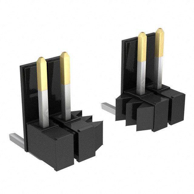
| 产品图片 |
|
| rohs | 否 |
| 产品系列 | 灯,Chicago Miniature 338 |
| MSCP | 0.04 MSCP |
| 产品型号 | 338 |
| 产品种类 | 灯 |
| 商标 | Chicago Miniature |
| 寿命 | 6000 Hrs |
| 封装 | Bulk |
| 工作电流 | 0.06 A |
| 工作电源电压 | 2.7 V |
| 工厂包装数量 | 100 |
| 灯大小 | T-1 3/4 |
| 灯座类型 | Midget Flange |
| 灯类型 | Incandescent |
| 零件号别名 | 338-10PK |
| 颜色 | Clear |


- 商务部:美国ITC正式对集成电路等产品启动337调查
- 曝三星4nm工艺存在良率问题 高通将骁龙8 Gen1或转产台积电
- 太阳诱电将投资9.5亿元在常州建新厂生产MLCC 预计2023年完工
- 英特尔发布欧洲新工厂建设计划 深化IDM 2.0 战略
- 台积电先进制程称霸业界 有大客户加持明年业绩稳了
- 达到5530亿美元!SIA预计今年全球半导体销售额将创下新高
- 英特尔拟将自动驾驶子公司Mobileye上市 估值或超500亿美元
- 三星加码芯片和SET,合并消费电子和移动部门,撤换高东真等 CEO
- 三星电子宣布重大人事变动 还合并消费电子和移动部门
- 海关总署:前11个月进口集成电路产品价值2.52万亿元 增长14.8%


PDF Datasheet 数据手册内容提取
Nokia 5110/3310 Monochrome LCD Created by lady ada Last updated on 2020-05-18 09:22:33 PM EDT
Overview This is a quick tutorial for our 84x48 pixel monochrome LCD display. These displays are small, only about 1.5" diameter, but very readable due and comes with a backlight. This display is made of 84x48 individual pixels, so you can use it for graphics, text or bitmaps. These displays are inexpensive, easy to use, require only a few digital I/O pins and are fairly low power as well. To drive the display, you will need 3 to 5 digital output pins (depending on whether you want to manually control the chip select and reset lines). Another pin can be used to control (via on/off or PWM) the backlight. To make things easy for you, we've written a nice graphics library that can print text, pixels, rectangles, circles and lines! The library is © Adafruit Industries https://learn.adafruit.com/nokia-5110-3310-monochrome-lcd Page 3 of 36
written for the Arduino but can easily be ported to your favorite microcontroller. You can pick up one of these displays at the adafruit shop! (https://adafru.it/aIH) © Adafruit Industries https://learn.adafruit.com/nokia-5110-3310-monochrome-lcd Page 4 of 36
Power Requirements The display uses the PCD8544 controller chip from Philips and were used in Nokia 3310 and 5110 cell phones. This chip is designed to run only at 3.3V and have 3v communication levels, so for 5V microcontrollers a logic level shifter is required (otherwise you could easily damage the display). If you want to use the backlight, that can draw up to 80mA (4 white LEDs at 20mA each). The backlight pin is connected to a transistor so you can PWM all 4 LEDs at once from a microcontroller pin. © Adafruit Industries https://learn.adafruit.com/nokia-5110-3310-monochrome-lcd Page 5 of 36
Arduino Wiring The LCD runs at 3.3V so you'll need to use a level shifting chip to use with a 5V microcontroller. The following will assume that is the case. If you're running a 3.3V microcontroller system, you can skip the level shifter. We'll assume you want to use this in a breadboard, take a piece of 0.1" header 8 pins long and insert it into a breadboard. Slide either side of the LCD onto the header, the 'thicker' end is the top. Solder all the pins. © Adafruit Industries https://learn.adafruit.com/nokia-5110-3310-monochrome-lcd Page 6 of 36
Place the level shifter chip off to the side. Pin 1 is on the left here. © Adafruit Industries https://learn.adafruit.com/nokia-5110-3310-monochrome-lcd Page 7 of 36
We'll start with the power lines. the system must be powered by 3.3V so red here is connected to the 3V pin from the Arduino. Ground is black. Connect pin 1 of the 4050, the LCD VCC pin and the LCD backlight pin to 3.3V. Connect pin 8 of the 4050 and the GND pin of the LCD to ground. Verify you see the backlight LEDs light up © Adafruit Industries https://learn.adafruit.com/nokia-5110-3310-monochrome-lcd Page 8 of 36
Dimmable Backlight Option: Newer versions of these boards have a sightly different backlight circuit that is brighter than the older boards. You can add a pot to the backlight so that you can control the brightness. (This works with the older boards too, but the range of brightness will be lower). The optional pot can be wired as in the photo below: Next we'll start wiring up the data lines. Connect the RST (reset) pin of the LCD (orange wire) to pin 2 of the 4050 Connect the CS (chip select) pin (yellow wire) to pin 4 of the 4050. Connect the D/C (data/command) pin (green wire) to pin 6 of the 4050. © Adafruit Industries https://learn.adafruit.com/nokia-5110-3310-monochrome-lcd Page 9 of 36
Next, connect: DIN (data in) pin (blue wire) to pin 15 of the 4050 CLK(clock) pin (purple wire) to pin 12 of the 4050. Then we can connect the data lines from the arduino to the LCD. We can use any 5 pins but you may want to start with our example first. Arduino pin 3 (orange) goes to pin 3 of the 4050. Arduino pin 4 (yellow) goes to pin 5 of the 4050. Arduino pin 5 (green) goes to pin 7 of the 4050. Arduino pin 6 (blue) goes to pin 14 of the 4050. Arduino pin 7 (violet) goes to pin 11 of the 4050. © Adafruit Industries https://learn.adafruit.com/nokia-5110-3310-monochrome-lcd Page 10 of 36
Now you are ready to test! © Adafruit Industries https://learn.adafruit.com/nokia-5110-3310-monochrome-lcd Page 11 of 36
Arduino Testing You can find our Nokia Display Arduino library on github (https://adafru.it/aHn). You should install it through the Arduino Library Manager. Open up the Arduino Library Manager: Search for the Adafruit PCD8544 library and install it Search for the Adafruit GFX library and install it If using an earlier version of the Arduino IDE (prior to 1.8.10), also locate and install Adafruit_BusIO (newer versions will install this dependency automatically). We also have a great tutorial on Arduino library installation at: http://learn.adafruit.com/adafruit-all-about-arduino-libraries-install-use You should see the pcdtest example in File>Examples>Adafruit PCD8544 Nokia 5110 LCD library. Load that example and flash it to your Arduino © Adafruit Industries https://learn.adafruit.com/nokia-5110-3310-monochrome-lcd Page 12 of 36
You can control the backlight, its much brighter when you connect the backlight pin to 5V (you don't need a level shifter if you are using a Nokia display from Adafruit). You can control the backlight using an Arduino pin since there is a transistor on the board. © Adafruit Industries https://learn.adafruit.com/nokia-5110-3310-monochrome-lcd Page 13 of 36
Graphics Library We have a ready to go basic graphics library that has primitives for bitmaps, shapes and text. You can probably do everything you want using it. Because of the way the display works we need to buffer the entire display in ram which is 84x48 bits (504 bytes). However, screen updates are very fast. For more details about the Adafruit GFX library, please visit http://learn.adafruit.com/adafruit-gfx-graphics- library (https://adafru.it/aPx) - it supports lines, rectangles, roundrects, circles, text of different sizes etc. Note that since this display is MONOCHROMATIC it only supports two colors: BLACK or WHITE. BLACK is a displayed dot and WHITE is for erasing pixels Dont forget, after drawing anything to the screen, call display() to write it out to the LCD! © Adafruit Industries https://learn.adafruit.com/nokia-5110-3310-monochrome-lcd Page 14 of 36
Wiring (fewer pins) You can save some pins by connecting the CS pin to ground (this means you cant reuse the LCD's pins between screen updates but maybe thats OK. You can also connect the RST pin to the Arduino reset so that it will reset the screen automatically. © Adafruit Industries https://learn.adafruit.com/nokia-5110-3310-monochrome-lcd Page 15 of 36
CircuitPython Wiring It's easy to use the Nokia 5110/3310 LCD with CircuitPython and the Adafruit CircuitPython PCD8544 (https://adafru.it/God) module. This module allows you to easily write Python code to control the display. You can use this sensor with any CircuitPython microcontroller board or with a computer that has GPIO and Python thanks to Adafruit_Blinka, our CircuitPython-for-Python compatibility library (https://adafru.it/BSN). We'll cover how to wire the Nokia LCD to your CircuitPython microcontroller board. First assemble your LCD. We're going to show you how to wire it up to a Feather M4 Express. Because the logic levels on a Feather M4 Express are already 3.3v, you don't need a logic level shifter. Connect the LCD to your microcontroller board as shown below. Microcontroller GND to LCD Gnd Microcontroller 3V to LCD Vcc Microcontroller SCK to LCD Clk Microcontroller MOSI to LCD Din Microcontroller D6 to LCD D/C Microcontroller D5 to LCD CS Microcontroller D9 to LCD Rst Microcontroller D10 to LCD Led https://adafru.it/GtB https://adafru.it/GtB © Adafruit Industries https://learn.adafruit.com/nokia-5110-3310-monochrome-lcd Page 16 of 36
CircuitPython Setup CircuitPython Installation of PCD8544 Library To use the Nokia 5110/3310 LCD with your Adafruit CircuitPython board you'll need to install the Adafruit CircuitPython PCD8544 (https://adafru.it/God) module on your board. First make sure you are running the latest version of Adafruit CircuitPython (https://adafru.it/Amd) for your board. Next you'll need to install the necessary libraries to use the hardware--carefully follow the steps to find and install these libraries from Adafruit's CircuitPython library bundle (https://adafru.it/uap). Our CircuitPython starter guide has a great page on how to install the library bundle (https://adafru.it/ABU). If you choose, you can manually install the libraries individually on your board: adafruit_pcd8544 adafruit_framebuf adafruit_bus_device Before continuing make sure your board's lib folder or root filesystem has the adafruit_pcd8544.mpy, adafruit_framebuf.mpy and adafruit_bus_device files and folders copied over. Next connect to the board's serial REPL (https://adafru.it/Awz) so you are at the CircuitPython >>> prompt. © Adafruit Industries https://learn.adafruit.com/nokia-5110-3310-monochrome-lcd Page 17 of 36
CircuitPython Usage It's easy to use the Nokia 5110/3310 LCD with CircuitPython and the Adafruit CircuitPython PCD8544 (https://adafru.it/God) module. This module allows you to easily write Python code to control the display. You can use this display with any CircuitPython microcontroller board. To demonstrate the usage, we'll initialize the library and use Python code to control the LCD from the board's Python REPL. Initialization First need to initialize the SPI bus. To do that, run the following commands: import adafruit_pcd8544 import board import busio import digitalio spi = busio.SPI(board.SCK, MOSI=board.MOSI) dc = digitalio.DigitalInOut(board.D6) # data/command cs = digitalio.DigitalInOut(board.D5) # Chip select reset = digitalio.DigitalInOut(board.D9) # reset display = adafruit_pcd8544.PCD8544(spi, dc, cs, reset) The last three parameters to the initializer are the pins connected to the display's DC, CS, and reset lines in that order. Again make sure to use the right pin names as you have wired up to your board! Controlling the Backlight LED You can control the display backlight LED as well. Just be sure the LED line is wired up to your microcontroller. Just start by initializing it as a DigitalInOut output line. If you wired it to a different output, be sure to change the port accordingly. backlight = digitalio.DigitalInOut(board.D10) # backlight backlight.switch_to_output() To turn it on, just set it to True and to turn it off, just set it to False. # Turn Backlight on backlight.value = True #Turn Backlight off backlight.value = False Contrast and Bias Two important settings so that you can see what is on the display are the contrast and Bias Settings. Let's start by taking a look at the Bias Setting. © Adafruit Industries https://learn.adafruit.com/nokia-5110-3310-monochrome-lcd Page 18 of 36
Bias The Bias setting controls the amount of voltage that goes to the display. The higher the value, the darker the display will be. It's kind of like the brightness setting on a monitor, but will make the pixels more intense. A value of 4-5 is usually pretty good. For example, to set it to 5, you would type: display.bias = 5 Contrast The contrast setting controls the difference between the dark and light pixels and can be set to anywhere between 0- 127. This is like the contrast setting on a monitor. Too high of a value will make everything appear dark and to low of a value will make everything appear too light. A value of around 50-60 seems to look good. For example, to set it to 50, you would type: display.contrast = 50 You may want to play around with different combinations of these values to see what makes your particular display the most readable. Drawing The PCD8544 module currently supports a basic set of commands to draw on the display. You can set individual pixels, fill the screen, and write lines of text. To fill or clear the entire screen use the fill function. This function takes a parameter which specifies the color to fill with, either 0 for white or 1 for black. For example to fill the screen black: display.fill(1) display.show() © Adafruit Industries https://learn.adafruit.com/nokia-5110-3310-monochrome-lcd Page 19 of 36
Notice the fill function doesn't actually change the display. You must call show after making drawing commands to send the updated pixel data to the display! To clear the screen to white just call fill again but with the color 0: display.fill(0) display.show() To set a pixel use the pixel function. This function takes the following parameters: © Adafruit Industries https://learn.adafruit.com/nokia-5110-3310-monochrome-lcd Page 20 of 36
Pixel X position Pixel Y position Pixel color (0 = white, 1 = black) For example to set the first pixel black: display.pixel(0, 0, 1) display.show() Try setting other pixels white by changing the X and Y position. Remember you have to call show (https://adafru.it/Dvz) after setting pixels to see them appear! Text To write text to your display, you must download a font file and copy it to your CIRCUITPY drive. Click the button below to download the file, and then copy font5x8.bin to your CIRCUITPY drive. https://adafru.it/DvA https://adafru.it/DvA You can write a line of text with the text function. This function takes the following parameters: String of text Text X position Text Y position Text color (0 = white, 1 = black) For example to clear the screen and then write two lines of text: © Adafruit Industries https://learn.adafruit.com/nokia-5110-3310-monochrome-lcd Page 21 of 36
display.fill(0) display.text('Hello', 0, 0, 1) display.text('World', 0, 10, 1) display.show() Notice the second line of text starts at Y position 10, this moves it down the display 10 pixels so it's below the first line of text. The font used by the text function is 8 pixels tall so a size of 10 gives a bit of room between the lines. Invert Finally you can invert the display colors with the invert property: display.invert = True © Adafruit Industries https://learn.adafruit.com/nokia-5110-3310-monochrome-lcd Page 22 of 36
Note that the invert function doesn't need to have show called after it to see the change. To go back to a non-inverted display run: display.invert = False That's all there is to drawing on the Nokia 5110/3310 LCD display with CircuitPython! The drawing functions are basic but provide building blocks for more advanced usage. For example you can display text with sensor readings or other state, or even program a simple game like pong! © Adafruit Industries https://learn.adafruit.com/nokia-5110-3310-monochrome-lcd Page 23 of 36
Full Example Code import time import board import busio import digitalio import adafruit_pcd8544 # Initialize SPI bus and control pins spi = busio.SPI(board.SCK, MOSI=board.MOSI) dc = digitalio.DigitalInOut(board.D6) # data/command cs = digitalio.DigitalInOut(board.D5) # Chip select reset = digitalio.DigitalInOut(board.D9) # reset display = adafruit_pcd8544.PCD8544(spi, dc, cs, reset) display.bias = 4 display.contrast = 60 # Turn on the Backlight LED backlight = digitalio.DigitalInOut(board.D10) # backlight backlight.switch_to_output() backlight.value = True print("Pixel test") # Clear the display. Always call show after changing pixels to make the display # update visible! display.fill(0) display.show() # Set a pixel in the origin 0,0 position. display.pixel(0, 0, 1) # Set a pixel in the middle position. display.pixel(display.width // 2, display.height // 2, 1) # Set a pixel in the opposite corner position. display.pixel(display.width - 1, display.height - 1, 1) display.show() time.sleep(2) print("Lines test") # we'll draw from corner to corner, lets define all the pair coordinates here corners = ( (0, 0), (0, display.height - 1), (display.width - 1, 0), (display.width - 1, display.height - 1), ) display.fill(0) for corner_from in corners: for corner_to in corners: display.line(corner_from[0], corner_from[1], corner_to[0], corner_to[1], 1) display.show() time.sleep(2) print("Rectangle test") display.fill(0) © Adafruit Industries https://learn.adafruit.com/nokia-5110-3310-monochrome-lcd Page 24 of 36
display.fill(0) w_delta = display.width / 10 h_delta = display.height / 10 for i in range(11): display.rect(0, 0, int(w_delta * i), int(h_delta * i), 1) display.show() time.sleep(2) print("Text test") display.fill(0) display.text("hello world", 0, 0, 1) display.text("this is the", 0, 8, 1) display.text("CircuitPython", 0, 16, 1) display.text("adafruit lib-", 0, 24, 1) display.text("rary for the", 0, 32, 1) display.text("PCD8544! :) ", 0, 40, 1) display.show() while True: display.invert = True time.sleep(0.5) display.invert = False time.sleep(0.5) © Adafruit Industries https://learn.adafruit.com/nokia-5110-3310-monochrome-lcd Page 25 of 36
Python Wiring It's easy to use the Nokia 5110/3310 LCD with Python and the Adafruit CircuitPython PCD8544 (https://adafru.it/God) module. This module allows you to easily write Python code to control the display. We'll cover how to wire the Nokia LCD to your Raspberry Pi. First assemble your LCD. Since there's dozens of Linux computers/boards you can use we will show wiring for Raspberry Pi. For other platforms, please visit the guide for CircuitPython on Linux to see whether your platform is supported (https://adafru.it/BSN). Connect the LCD as shown below to your Raspberry Pi. Raspberry Pi GND to LCD Gnd Raspberry Pi 3.3V to LCD Vcc Raspberry Pi SCK (GPIO 11) to LCD Clk Raspberry Pi MOSI (GPIO 10) to LCD Din Raspberry Pi GPIO 6 to LCD D/C Raspberry Pi CE0 (GPIO 8) to LCD CS Raspberry Pi GPIO 5 to LCD Rst Raspberry Pi GPIO 13 to LCD Led https://adafru.it/Gue https://adafru.it/Gue © Adafruit Industries https://learn.adafruit.com/nokia-5110-3310-monochrome-lcd Page 26 of 36
Python Setup You'll need to install the Adafruit_Blinka library that provides the CircuitPython support in Python. This may also require enabling SPI on your platform and verifying you are running Python 3. Since each platform is a little different, and Linux changes often, please visit the CircuitPython on Linux guide to get your computer ready (https://adafru.it/BSN)! Python Installation of PCD8544 Library Once that's done, from your command line run the following command: pip3 install adafruit-circuitpython-pcd8544 If your default Python is version 3 you may need to run 'pip' instead. Just make sure you aren't trying to use CircuitPython on Python 2.x, it isn't supported! If that complains about pip3 not being installed, then run this first to install it: sudo apt-get install python3-pip DejaVu TTF Font Raspberry Pi usually comes with the DejaVu font already installed, but in case it didn't, you can run the following to install it: sudo apt-get install ttf-dejavu Pillow Library We also need PIL, the Python Imaging Library, to allow using text with custom fonts. There are several system libraries that PIL relies on, so installing via a package manager is the easiest way to bring in everything: sudo apt-get install python3-pil That's it. You should be ready to go. © Adafruit Industries https://learn.adafruit.com/nokia-5110-3310-monochrome-lcd Page 27 of 36
Python Usage It's easy to use the Nokia 5110/3310 LCD with CircuitPython and the Adafruit CircuitPython PCD8544 (https://adafru.it/God) module. This module allows you to easily write Python code to control the display. You can use this display with a computer that has GPIO and Python thanks to Adafruit_Blinka, our CircuitPython-for- Python compatibility library (https://adafru.it/BSN). To demonstrate the usage, we'll initialize the library and use Python code to control the LCD from the board's Python REPL. Since we are running full CPython on our Linux/computer, we can take advantage of the powerful Pillow image drawing library to handle text, shapes, graphics, etc. Pillow is a gold standard in image and graphics handling, you can read about all it can do here (https://adafru.it/FU7). Initialization First need to initialize the SPI bus. To do that, run the following commands: import adafruit_pcd8544 import board import busio import digitalio spi = busio.SPI(board.SCK, MOSI=board.MOSI) dc = digitalio.DigitalInOut(board.D6) # data/command cs = digitalio.DigitalInOut(board.CE0) # Chip select reset = digitalio.DigitalInOut(board.D5) # reset display = adafruit_pcd8544.PCD8544(spi, dc, cs, reset) The last three parameters to the initializer are the pins connected to the display's DC, CS, and reset lines in that order. Again make sure to use the right pin names as you have wired up to your board! Controlling the Backlight LED You can control the display backlight LED as well. Just be sure the LED line is wired up to your microcontroller. Just start by initializing it as a DigitalInOut output line. If you wired it to a different output, be sure to change the port accordingly. backlight = digitalio.DigitalInOut(board.D13) # backlight backlight.switch_to_output() To turn it on, just set it to True and to turn it off, just set it to False. # Turn Backlight on backlight.value = True #Turn Backlight off backlight.value = False © Adafruit Industries https://learn.adafruit.com/nokia-5110-3310-monochrome-lcd Page 28 of 36
Contrast and Bias Two important settings so that you can see what is on the display are the contrast and Bias Settings. Let's start by taking a look at the Bias Setting. Bias The Bias setting controls the amount of voltage that goes to the display. The higher the value, the darker the display will be. It's kind of like the brightness setting on a monitor, but will make the pixels more intense. A value of 4-5 is usually pretty good. For example, to set it to 5, you would type: display.bias = 5 Contrast The contrast setting controls the difference between the dark and light pixels and can be set to anywhere between 0- 127. This is like the contrast setting on a monitor. Too high of a value will make everything appear dark and to low of a value will make everything appear too light. A value of around 50-60 seems to look good. For example, to set it to 50, you would type: display.contrast = 50 You may want to play around with different combinations of these values to see what makes your particular display the most readable. Example Code """ This demo will fill the screen with white, draw a black box on top and then print Hello World! in the center of the display This example is for use on (Linux) computers that are using CPython with Adafruit Blinka to support CircuitPython libraries. CircuitPython does not support PIL/pillow (python imaging library)! """ import board import busio import digitalio from PIL import Image, ImageDraw, ImageFont import adafruit_pcd8544 # Parameters to Change BORDER = 5 FONTSIZE = 10 spi = busio.SPI(board.SCK, MOSI=board.MOSI) dc = digitalio.DigitalInOut(board.D6) # data/command cs = digitalio.DigitalInOut(board.CE0) # Chip select reset = digitalio.DigitalInOut(board.D5) # reset display = adafruit_pcd8544.PCD8544(spi, dc, cs, reset) © Adafruit Industries https://learn.adafruit.com/nokia-5110-3310-monochrome-lcd Page 29 of 36
# Contrast and Brightness Settings display.bias = 4 display.contrast = 60 # Turn on the Backlight LED backlight = digitalio.DigitalInOut(board.D13) # backlight backlight.switch_to_output() backlight.value = True # Clear display. display.fill(0) display.show() # Create blank image for drawing. # Make sure to create image with mode '1' for 1-bit color. image = Image.new("1", (display.width, display.height)) # Get drawing object to draw on image. draw = ImageDraw.Draw(image) # Draw a black background draw.rectangle((0, 0, display.width, display.height), outline=255, fill=255) # Draw a smaller inner rectangle draw.rectangle( (BORDER, BORDER, display.width - BORDER - 1, display.height - BORDER - 1), outline=0, fill=0, ) # Load a TTF font. font = ImageFont.truetype("/usr/share/fonts/truetype/dejavu/DejaVuSans.ttf", FONTSIZE) # Draw Some Text text = "Hello World!" (font_width, font_height) = font.getsize(text) draw.text( (display.width // 2 - font_width // 2, display.height // 2 - font_height // 2), text, font=font, fill=255, ) # Display image display.image(image) display.show() Let's take a look at the sections of code one by one. We start by importing the board so that we can access the pin definitions, busio so we can initialize SPI, digitalio, several PIL modules for Image Drawing, and the adafruit_pcd8544 driver. © Adafruit Industries https://learn.adafruit.com/nokia-5110-3310-monochrome-lcd Page 30 of 36
import board import busio import digitalio from PIL import Image, ImageDraw, ImageFont import adafruit_pcd8544 In order to make it easy to change display sizes, we'll define a few variables in one spot here. We have the border size and font size, which we will explain a little further below. BORDER = 5 FONTSIZE = 10 Next we set the SPI object to the board's SPI with busio.SPI(). We also define some Pins that will be used for the display and initialize the display. See the initialization section above for more details. spi = busio.SPI(board.SCK, MOSI=board.MOSI) dc = digitalio.DigitalInOut(board.D6) # data/command cs = digitalio.DigitalInOut(board.CE0) # Chip select reset = digitalio.DigitalInOut(board.D5) # reset display = adafruit_pcd8544.PCD8544(spi, dc, cs, reset) Next we set the Bias and Contrast. See the Contrast and Bias section for more details. # Contrast and Brightness Settings display.bias = 4 display.contrast = 60 After that we setup the backlight. See the Backlight section above for more information. # Turn on the Backlight LED backlight = digitalio.DigitalInOut(board.D13) # backlight backlight.switch_to_output() backlight.value = True Next we clear the display in case it was initialized with any random artifact data. # Clear display. display.fill(0) display.show() Next, we need to initialize PIL to create a blank image to draw on. Think of it as a virtual canvas. Since this is a monochrome display, we set it up for 1-bit color, meaning a pixel is either white or black. We can make use of the LCD's width and height properties as well. © Adafruit Industries https://learn.adafruit.com/nokia-5110-3310-monochrome-lcd Page 31 of 36
# Create blank image for drawing. # Make sure to create image with mode '1' for 1-bit color. image = Image.new('1', (display.width, display.height)) # Get drawing object to draw on image. draw = ImageDraw.Draw(image) Now we start the actual drawing. Here we are telling it we want to draw a rectangle from (0,0), which is the upper left, to the full width and height of the display. We want it both filled in and having an outline of black, so we pass 255 for both numbers, which represents the amount of fill. # Draw a black background draw.rectangle((0, 0, display.width, display.height), outline=255, fill=255) If we ran the code now, it would still show a blank display because we haven't told python to use our virtual canvas yet. You can skip to the end if you would like to see how to do that. This is what our canvas currently looks like in memory. Next we will create a smaller white rectangle. The easiest way to do this is to draw another rectangle a little smaller than the full screen with no fill or outline and place it in a specific location. In this case, we will create a rectangle that is 5 pixels smaller on each side. This is where the BORDER variable comes into use. It makes calculating the size of the second rectangle much easier. We want the starting coordinate, which consists of the first two parameters, to be our BORDER value. Then for the next two parameters, which are our ending coordinates, we want to subtract our border value from the width and height. Also, because this is a zero-based coordinate system, we also need to subtract 1 from each number. # Draw a smaller inner rectangle draw.rectangle((BORDER, BORDER, display.width - BORDER - 1, display.height - BORDER - 1), outline=0, fill=0) © Adafruit Industries https://learn.adafruit.com/nokia-5110-3310-monochrome-lcd Page 32 of 36
Here's what our virtual canvas looks like in memory. Now drawing text with PIL is pretty straightforward. First we start by setting the font to the default system text. After that we define our text and get the size of the text. We're grabbing the size that it would render at so that we can calculate the center position. Finally, we take the font size and screen size to calculate the position we want to draw the text at and it appears in the center of the screen. # Load a TTF font. font = ImageFont.truetype('/usr/share/fonts/truetype/dejavu/DejaVuSans.ttf', FONTSIZE) # Draw Some Text text = "Hello World!" (font_width, font_height) = font.getsize(text) draw.text((display.width//2 - font_width//2, display.height//2 - font_height//2), text, font=font, fill=255) Finally, we need to display our virtual canvas to the LCD and we do that with 2 commands. First we set the image to the screen, then we tell it to show the image. # Display image display.image(image) display.show() Don't forget you MUST call display.image(image) and display.show() to actually display the graphics. The LCD � takes a while to draw so cluster all your drawing functions into the buffer (fast) and then display them once to the LCD (slow) Here's what the final output should look like. © Adafruit Industries https://learn.adafruit.com/nokia-5110-3310-monochrome-lcd Page 33 of 36
© Adafruit Industries https://learn.adafruit.com/nokia-5110-3310-monochrome-lcd Page 34 of 36
Downloads Our PCD8544 (Nokia 5110) LCD display Arduino library is on github (https://adafru.it/aHn) which comes with example code. This library uses 1/2 Kbytes of RAM since it needs to buffer the entire display but its very fast! The code is simple to adapt to any other microcontroller. You'll also need to get the Adafruit GFX Graphics core library which can print text, bitmaps, pixels, rectangles, circles and lines, also available on github (https://adafru.it/aJa). The PCD8544 datasheet tells you all about what the display can do (https://adafru.it/aTN). © Adafruit Industries https://learn.adafruit.com/nokia-5110-3310-monochrome-lcd Page 35 of 36
© Adafruit Industries Last Updated: 2020-05-18 09:22:33 PM EDT Page 36 of 36