 Datasheet下载
- 型号: 325540009-50
- 制造商: MEASUREMENT SPECIALTIES
- 库位|库存: xxxx|xxxx
- 要求:
| 数量阶梯 | 香港交货 | 国内含税 |
| +xxxx | $xxxx | ¥xxxx |
查看当月历史价格
查看今年历史价格
325540009-50产品简介:
ICGOO电子元器件商城为您提供325540009-50由MEASUREMENT SPECIALTIES设计生产,在icgoo商城现货销售,并且可以通过原厂、代理商等渠道进行代购。 325540009-50价格参考。MEASUREMENT SPECIALTIES325540009-50封装/规格:压力传感器,变送器, 绝对 压力 传感器 0.15 PSI ~ 15.95 PSI(1 kPa ~ 110 kPa) 16 b 模块。您可以下载325540009-50参考资料、Datasheet数据手册功能说明书,资料中有325540009-50 详细功能的应用电路图电压和使用方法及教程。
TE Connectivity Measurement Specialties 品牌下的型号 325540009-50 是一款压力传感器/变送器,广泛应用于需要精确测量压力的工业和商业场景。以下是其主要应用场景:

1. 工业自动化与控制:该型号的压力传感器可用于监测和控制工业流程中的压力参数,例如液压系统、气动系统以及化学反应釜等设备的压力监控,确保生产过程的安全性和稳定性。

2. 暖通空调(HVAC)系统:在 HVAC 系统中,这款传感器可以用来测量制冷剂压力或空气流动中的差压,帮助优化能源效率并维持舒适的室内环境。

3. 水处理与水务管理:用于供水管网、污水处理厂及泵站的压力监测,确保水流稳定,并及时发现管道泄漏或堵塞等问题。

4. 医疗设备:在某些非侵入式医疗设备中,如呼吸机、血压计或其他需要精确压力检测的仪器中,这种传感器能够提供高精度的数据支持。

5. 汽车制造与测试:适用于发动机测试台架、刹车系统性能评估以及轮胎充气压力检测等领域,为汽车研发和维护提供准确的压力信息。

6. 航空航天与国防:可用于飞行器燃油系统、液压制动系统以及环境控制系统中的压力监控,满足苛刻工况下的使用需求。

7. 实验室研究与分析:在科学研究实验中,这款传感器可以帮助研究人员精确记录气体或液体的压力变化,辅助完成复杂数据分析。

8. 食品饮料加工行业:对于涉及灌装、巴氏杀菌等工艺环节的企业来说,利用此类型号的压力变送器可以有效保证产品质量与安全。

总之,TE Connectivity 的 325540009-50 型号压力传感器凭借其出色的性能表现,在众多领域内发挥着重要作用,为各种应用场合提供了可靠的解决方案。
| 参数 | 数值 |
| 产品目录 | |
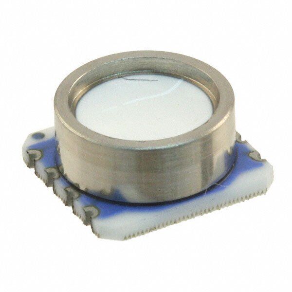
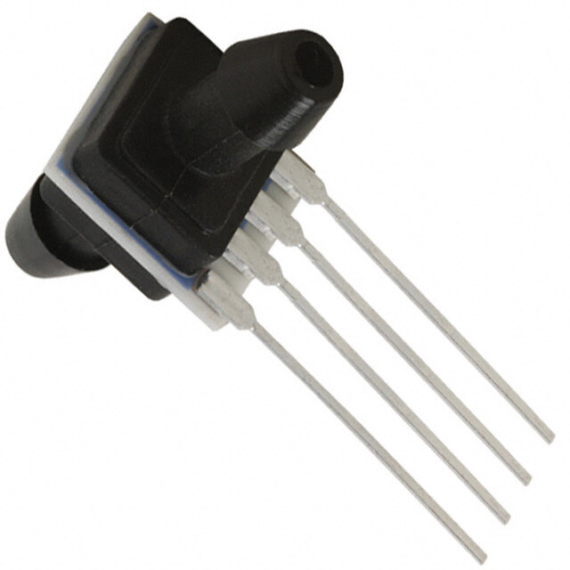
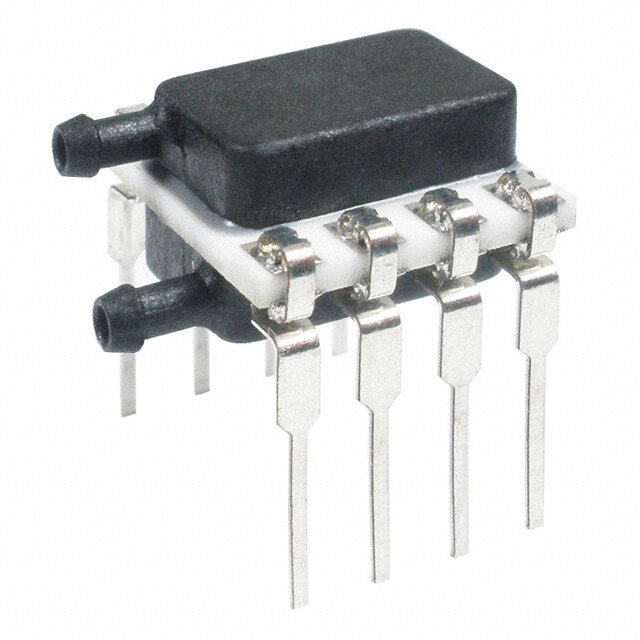
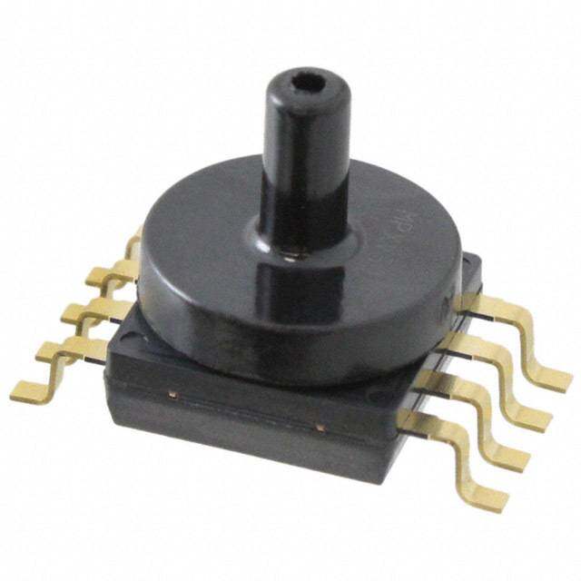
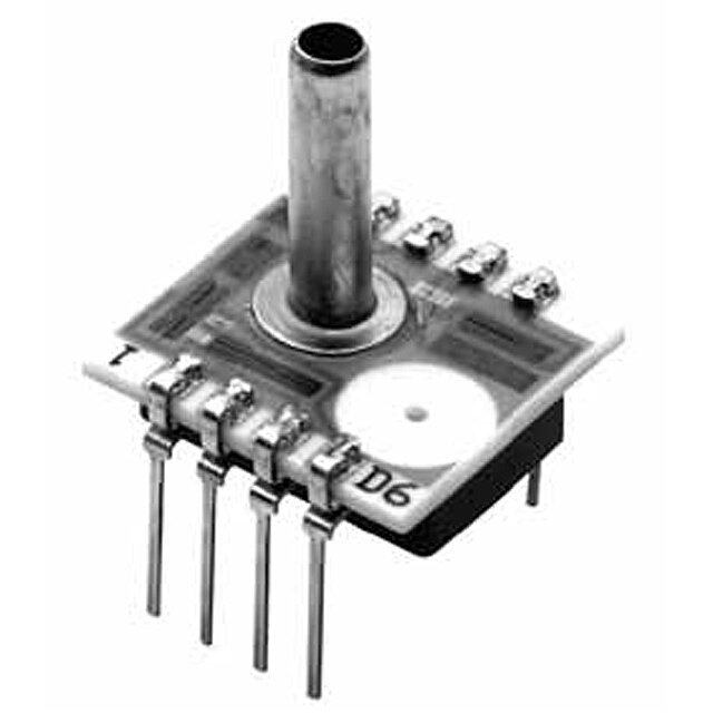
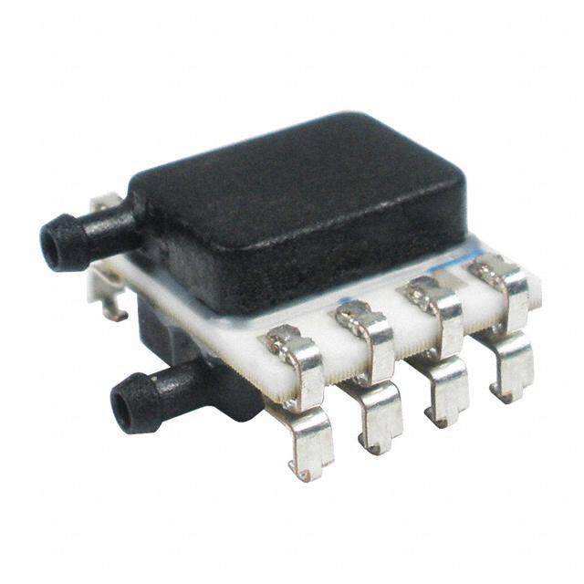
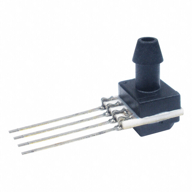
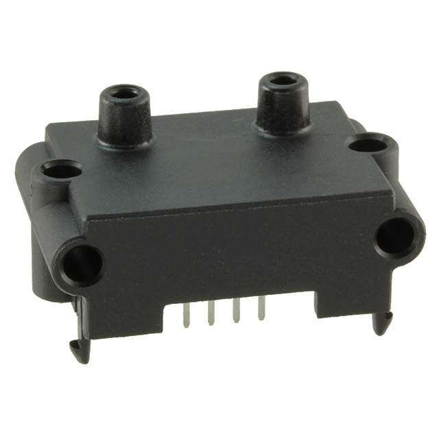
| 描述 | MODULE BAROMETER MINITURE SENSOR板机接口压力传感器 1BAR WHITE GEL T&R MS5540-CM |
| 产品分类 | |
| 品牌 | Measurement Specialties Inc. |
| 产品手册 | |
| 产品图片 |
|
| rohs | 符合RoHS无铅 / 符合限制有害物质指令(RoHS)规范要求 |
| 产品系列 | 板机接口压力传感器,Measurement Specialties, Inc. 325540009-50- |
| mouser_ship_limit | 该产品可能需要其他文件才能进口到中国。 |
| 数据手册 | |
| 产品型号 | 325540009-50 |
| 产品目录页面 | |
| 产品种类 | 板机接口压力传感器 |
| 其它名称 | 223-1098-2 |
| 出厂设置 | - |
| 压力类型 | 绝对 |
| 商标 | Measurement Specialties, Inc. |
| 封装 | Reel |
| 封装/外壳 | 模块 |
| 工作压力 | 0.14 PSI ~ 15.9 PSI,10 ~ 1100 mbar |
| 工作温度 | -40°C ~ 85°C |
| 工厂包装数量 | 1000 |
| 标准包装 | 1,000 |
| 电压-电源 | 2.2 V ~ 3.6 V |
| 端口尺寸 | - |
| 端子类型 | PCB |
| 精度 | - |
| 输出 | 数字 |
| 零件号别名 | MS5534A |


- 商务部:美国ITC正式对集成电路等产品启动337调查
- 曝三星4nm工艺存在良率问题 高通将骁龙8 Gen1或转产台积电
- 太阳诱电将投资9.5亿元在常州建新厂生产MLCC 预计2023年完工
- 英特尔发布欧洲新工厂建设计划 深化IDM 2.0 战略
- 台积电先进制程称霸业界 有大客户加持明年业绩稳了
- 达到5530亿美元!SIA预计今年全球半导体销售额将创下新高
- 英特尔拟将自动驾驶子公司Mobileye上市 估值或超500亿美元
- 三星加码芯片和SET,合并消费电子和移动部门,撤换高东真等 CEO
- 三星电子宣布重大人事变动 还合并消费电子和移动部门
- 海关总署:前11个月进口集成电路产品价值2.52万亿元 增长14.8%

PDF Datasheet 数据手册内容提取
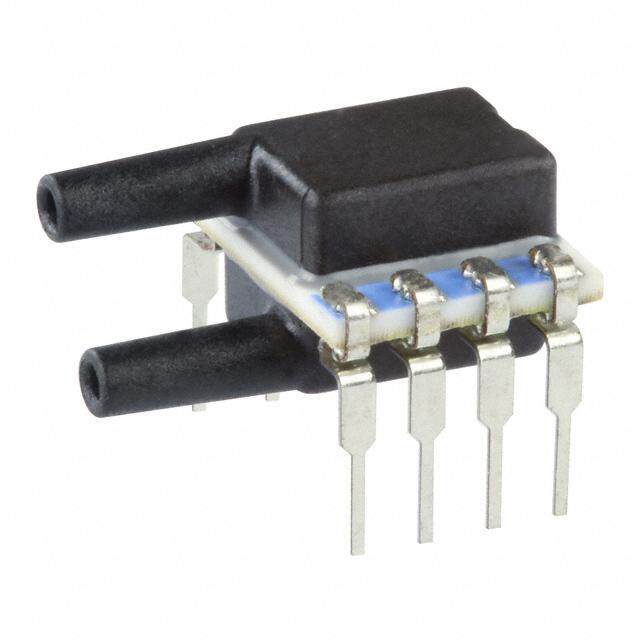
MS5540C Miniature Barometer Module The MS5540C is a SMD-hybrid device including a precision piezoresistive pressure sensor and an ADC-Interface IC. The MS5540C HE is the high endurance version of MS5540C sensor. It is a miniature version of the MS5534C barometer/altimeter module and provides a 16 Bit data word from a pressure and temperature dependent voltage. MS5540C is a low power, low voltage device with automatic power down (ON/OFF) switching. A 3-wire interface is used for all communications with a micro- FEATURES controller. Compared to MS5534A the pressure range (measurement down 10 - 1100 mbar absolute pressure range to 10 mbar) has been improved. The MS5540C is fully software 6 coefficients for software compensation stored on- compatible to the MS5534C and previous versions of MS5540. In chip addition, the MS5540C is from its outer dimensions compatible to the MS54XX series of pressure sensors. Compared to the Piezoresistive silicon micromachined sensor previous version the ESD sensitivity level has been improved to Integrated miniature pressure sensor 6.2 x 6.4 mm 4kV on all pins. The gel protection of the sensor provides a water 16 Bit ADC protection sufficient for 100 m waterproof watches without any 3-wire serial interface additional protection. 1 system clock line (32.768 kHz) Low voltage and low power consumption High Endurance (HE version) APPLICATIONS Mobile altimeter / barometer systems Weather control systems Adventure or multi-mode watches GPS receivers High endurance pad technology (HE version) SENSOR SOLUTIONS ///MS5540C 06/2017 Page 1
MS5540C Miniature Barometer Module TECHNICAL DATA Sensor Performances (VDD = 3 V) Pressure Min Typ Max Unit Range 10 1100 mbar ADC 16 bit Resolution 0.1 mbar Accuracy 0°C to +50°C, -1 +1 mbar 300 to 1000 mbar Accuracy -40°C to +85°C -2 +5 mbar 300 to 1000 mbar Response time 35 ms Long term stability -1 mbar/yr Temperature Min Typ Max Unit Range -40 +85 °C Resolution 0.005 0.015 °C Accuracy -0.8 +0.8 °C FUNCTIONAL BLOCK DIAGRAM VDD MCLK Input MUX SENSOR +IN InDteigriftaacle DIN ADC dig. DOUT -IN Filter SCLK Sensor Memory Interface IC (PROM) 64 bits SGND GND SENSOR SOLUTIONS ///MS5540C 08/2017 Page 2
MS5540C Miniature Barometer Module PERFORMANCE SPECIFICATIONS ABSOLUTE MAXIMUM RATINGS Parameter Symbol Conditions Min Max Unit Notes Supply voltage VDD Ta = 25 °C -0.3 4 V Storage temperature TS -40 +85 °C 1 Overpressure P Ta = 25 °C (ISO22810) 10 bar 2 NOTES 1) Storage in an environment of dry and non-corrosive gases. 2) The MS5540C is qualified referring to the ISO 22810 standard and can withstand an absolute pressure of 10 bar in salt water or 100 m water respectively. ELECTRICAL CHARACTERISTICS (Ta = 25 °C, VDD = 3.0 V unless noted otherwise) Parameter Symbol Conditions Min Typ Max Unit mbar Operating pressure range p 10 1100 abs. Supply voltage VDD 2.2 3.0 3.6 V Supply current, VDD = 3.0 V average (1) Iavg 4 µA during conversion (2) Isc 1 mA standby (no conversion) Iss 0.1 µA Current consumption into MCLK MCLK = 32.768 kHz 0.5 µA (3) Operating temperature range T -40 +85 °C Conversion time tconv MCLK = 32.768 kHz 35 ms External clock signal (4) MCLK 30.000 32.768 35.000 kHz Duty cycle of MCLK 40/60 50/50 60/40 % Serial data clock SCLK 500 kHz NOTES 1) Under the assumption of one conversion every second. Conversion means either a pressure or a temperature measurement started by a command to the serial interface of MS5540C. 2) During conversion the sensor will be switched on and off in order to reduce power consumption; the total on time within a conversion is about 2 ms. 3) This value can be reduced by switching off MCLK while MS5540C is in standby mode. 4) It is strongly recommended that a crystal oscillator be used because the device is sensitive to clock jitter. A square-wave form of the clock signal is a must. SENSOR SOLUTIONS ///MS5540C 08/2017 Page 3
MS5540C Miniature Barometer Module PERFORMANCE SPECIFICATIONS (CONTINUED) PRESSURE OUTPUT CHARACTERISTICS With the calibration data stored in the interface IC of the MS5540C, the following characteristics can be achieved: (VDD = 3.0 V unless noted otherwise) Parameter Conditions Min Typ Max Unit Notes Resolution 0.1 mbar 1 p =750 .. 1100 mbar Absolute Pressure Accuracy -1.5 +1.5 mbar 2, 6 Ta = 25°C p =750 .. 1100 mbar Relative Pressure Accuracy -0.5 +0.5 mbar 3, 6 Ta = 25°C T = 0 .. +50°C -1 +1 mbar 4, 6 Relative Pressure Error over p =300 .. 1000 mbar Temperature T = -40 .. +85°C -2 +5 mbar 4 p =300 .. 1000 mbar Long-term Stability 12 months -1 mbar 5 Maximum Error over Supply VDD = 2.2 .. 3.6 V -1.6 1.6 mbar Voltage p = const. NOTES 1) A stable pressure reading of the given resolution requires taking the average of 2 to 4 subsequent pressure values due to noise of the ADC. 2) Maximum error of pressure reading over the pressure range. 3) Maximum error of pressure reading over the pressure range after offset adjustment at one pressure point. 4) With the second-order temperature compensation as described in Section "FUNCTION". See next section for typical operating curves. 5) The long-term stability is measured with non-soldered devices. 6) Wet/dry cycle: sensor must be dried typically once a day. TEMPERATURE OUTPUT CHARACTERISTICS This temperature information is not required for most applications, but it is necessary to allow for temperature compensation of the output. (VDD = 3.0 V unless noted otherwise) Parameter Conditions Min Typ Max Unit Notes Resolution 0.005 0.01 0.015 °C T = 20 °C -0.8 0.8 °C Accuracy T = -40 .. + 85°C -2 +2 °C 1 Maximum Error over Supply Voltage VDD = 2.2 .. 3.6 V -0.2 +0.2 °C 2 NOTES 1) With the second-order temperature compensation as described in Section "FUNCTION". See next section for typical operating curves. 2) At Ta = 25 °C. SENSOR SOLUTIONS ///MS5540C 08/2017 Page 4
MS5540C Miniature Barometer Module PERFORMANCE SPECIFICATIONS (CONTINUED) DIGITAL INPUTS (T = -40 °C .. 85 °C, VDD = 2.2 V .. 3.6 V) Parameter Symbol Conditions Min Typ Max Unit Input High Voltage VIH 80% VDD 100% VDD V Input Low Voltage VIL 0% VDD 20% VDD V Signal Rise Time tr 200 ns Signal Fall Time tf 200 ns DIGITAL OUTPUTS (T = -40 °C .. 85 °C VDD = 2.2 V .. 3.6 V) Parameter Symbol Conditions Min Typ Max Unit Output High Voltage VOH Isource = 0.6 mA 80% VDD 100% VDD V Output Low Voltage VOL Isink = 0.6 mA 0% VDD 20% VDD V Signal Rise Time tr 200 ns Signal Fall Time tf 200 ns ANALOG DIGITAL CONVERTER (ADC) (T = -40 °C .. 85 °C VDD = 2.2 V .. 3.6 V) Parameter Symbol Conditions Min Typ Max Unit Resolution 16 Bit Linear Range 4'000 40'000 LSB Conversion Time MCLK = 32.768 kHz 35 ms INL Within linear range -5 +5 LSB SENSOR SOLUTIONS ///MS5540C 08/2017 Page 5
MS5540C Miniature Barometer Module TYPICAL PERFORMANCE CHARACTERISTICS ADC-value D1 vs Pressure (typical) ADC-value D2 vs Temperature (typical) 22000 40000 20000 35000 18000 ADC-value D1 (LSB)111246000000000 -284550°°°CCC ADC-value D2 (LSB)2350000000 10000 20000 8000 6000 15000 0 100 200 300 400 500 600 700 800 900 1000 1100 -40 -20 0 20 40 60 80 Pressure (mbar) Temperature (°C) Pressure error vs supply voltage (typical) Pressure Error Accuracy vs temperature (typical) 1 18 16 0.8 14 0.6 12 0.4 10 Pressure error (mbar)-00..2202.2 2.4 2.6 2.8 3 3.2 3.4 3.6 1830000000mmmbbbaarrar Pressure error (mbar) 2468 PPPPPPeeeeeerrrrrrrrrrrroooooorrrrrr((((((11883300000000000000,,,,1212,,12snsnttsndd tood ooorr orrddrddrdeedeeerrerr))r))r)) 0 -0.4 -2 -0.6 -4 -6 -0.8 -8 -1 -40 -20 0 20 40 60 80 Voltage (V) Temperature (°C) Temperature error vs supply voltage (typical) Temperature Error Accuracy vs temperature (typical) 0.15 15 0.1 10 Temperature error (°C)-00..005502.2 2.4 2.6 2.8 3 3.2 3.4 3.6 Temperature error (°C) 5 TcToareedlmmceurpp laeecartriaaolcttnuuu)rrlaee tieeorrnrroo)rr ((swtiathn d2anrdd 0 -0.1 -5 -0.15 -40 -20 0 20 40 60 80 Voltage (V) Temperature (°C) SENSOR SOLUTIONS ///MS5540C 08/2017 Page 6
MS5540C Miniature Barometer Module Absolute Pressure Accuracy after Calibration, 2nd order compensation 4 3 2 mbar) 1 85°C or ( 60°C ure err 0 205°C°C Press-1 -40°C -2 -3 -4 0 100 200 300 400 500 600 700 800 900 1000 1100 Pressure (mbar) SENSOR SOLUTIONS ///MS5540C 08/2017 Page 7
MS5540C Miniature Barometer Module FUNCTION GENERAL The MS5540C consists of a piezo-resistive sensor and a sensor interface IC. The main function of the MS5540C is to convert the uncompensated analogue output voltage from the piezo-resistive pressure sensor to a 16-bit digital value, as well as providing a 16-bit digital value for the temperature of the sensor. Measured pressure (16-bit) “D1” Measured temperature (16-bit) “D2” As the output voltage of a pressure sensor is strongly dependent on temperature and process tolerances, it is necessary to compensate for these effects. This compensation procedure must be performed by software using an external microcontroller. D1 Pressure Calculation D2 in external micro- Word 1..4 controller Temperature Sensor For both pressure and temperature measurement the same ADC is used (sigma delta converter): • for the pressure measurement, the differential output voltage from the pressure sensor is converted • for the temperature measurement, the sensor bridge resistor is sensed and converted During both measurements the sensor will only be switched on for a very short time in order to reduce power consumption. As both, the bridge bias and the reference voltage for the ADC are derived from V , the digital output DD data is independent of the supply voltage. FACTORY CALIBRATION Every module is individually factory calibrated at two temperatures and two pressures. As a result, 6 coefficients necessary to compensate for process variations and temperature variations are calculated and stored in the 64-bit PROM of each module. These 64-bit (partitioned into four words of 16-bit) must be read by the microcontroller software and used in the program converting D1 and D2 into compensated pressure and temperature values. PRESSURE AND TEMPERATURE MEASUREMENT The sequence of reading pressure and temperature as well as of performing the software compensation is depicted in Fig. 3 and Fig. 5. First Word1 to Word4 have to be read through the serial interface. This can be done once after reset of the microcontroller that interfaces to the MS5540C. Next, the compensation coefficients C1 to C6 are extracted using bit-wise logical- and shift-operations (refer to Fig. 4 for the bit-pattern of Word1 to Word4). For the pressure measurement, the microcontroller has to read the 16-bit values for pressure (D1) and temperature (D2) via the serial interface in a loop (for instance every second). Then, the compensated pressure is calculated out of D1, D2 and C1 to C6 according to the algorithm in Fig. 3 (possibly using quadratic temperature compensation according to Fig. 5). All calculations can be performed with signed 16-bit variables. Results of multiplications may be up to 32-bit long (+sign). In the flow according to Fig. 3 a division follows each multiplication. This division can be performed by bit-wise shifting (divisors are to the power of 2). It is ensured that the results of these divisions are less than 65536 (16 bit). For the timing of signals to read out Word1 to Word4, D1, and D2 please refer to the paragraph “Serial Interface". SENSOR SOLUTIONS ///MS5540C 08/2017 Page 8
MS5540C Miniature Barometer Module Basic equations: Example: Start stem ation Read calibratPioRnO dMat ao f( fMacSt5o5ry4 0caCl ibrated) from WWoorrdd12 == 4460921470 ys Sali Word1, Word2, Word3 and Word4 (4x16 Bit) Word3 = 25172 niti Word4 = 47212 i Convert calibration data into coefficients: (see bit pattern of Word1-Word4) SENST1 C1 = 23470 C1: Pressure sensitivity (15 Bit) OFFT1 C2: Pressure offset (12 Bit) TCS C2 = 1324 C3: Temperature coefficient of pressure sensitivity (10 Bit) TCO C3 = 737 CC45:: TReemfepreenracteu rTee cmopeeffriaciteunret of pressure offset ((1101 BBiitt)) TTrEefM PSENS C4 = 393 C6: Temperature coefficient of the temperature (6 Bit) C5 = 628 C6 = 25 (Refer to application note AN516 for limits of coefficients and calculated results) nt e Read digital pressure value from MS5540C m re D1 (16 Bit) D1 = 16460 u s a e m Read digital temperature value from MS5540C e ur D2 (16 Bit) D2 = 27856 at r e mp Calculate calibration temperature UT1 = 25248 d te UT1 = 8*C5+20224 n a re Calculate actual temperature u s Pres Dteimffepreernactuer bee: tween actual temperature and reference dT(D2) = D2 - Tref dT = 2608 dT = D2 - UT1 TEMP(D2) = 20°+dT(D2)*TEMPSENS TEMP = 391 Actual temperature: TEMP = 200 + dT*(C6+50)/210 (0.1°C resolution) = 39.1 °C Calculate temperature compensated pressure Offset at actual temperature: OFF(D2) = OFFT1+TCO*dT(D2) OFF = 5220 OFF = C2*4 + ((C4-512)*dT)/212 Sensitivity at actual temperature: SENS(D2) = SENST1+TCS*dT(D2) SENS = 49923 SENS = C1 + (C3*dT)/210 + 24576 X = 23093 X = (SENS * (D1-7168))/214 - OFF Temperature compensated pressure: P(D1,D2) = D1*SENS(D2)-OFF(D2) P = X*10/25 + 250*10 (0.1 mbar resolution) P = 9716 = 971.6 mbar Display pressure and temperature value Fig. 3: Flow chart for pressure and temperature reading and software compensation SENSOR SOLUTIONS ///MS5540C 08/2017 Page 9
MS5540C Miniature Barometer Module NOTES 1) Readings of D2 can be done less frequently, but the display will be less stable in this case. 2) For a stable display of 1 mbar resolution, it is recommended to display the average of 8 subsequent pressure values. C1 (15 Bit) C5/I 1 Bit Word1 DB14 DB13 DB12 DB11 DB10 DB9 DB8 DB7 DB6 DB5 DB4 DB3 DB2 DB1 DB0 DB10 C5/II (10 Bit) C6 (6 Bit) Word2 DB9 DB8 DB7 DB6 DB5 DB4 DB3 DB2 DB1 DB0 DB5 DB4 DB3 DB2 DB1 DB0 C4 (10 Bit) C2/I (6 Bit) Word3 DB9 DB8 DB7 DB6 DB5 DB4 DB3 DB2 DB1 DB0 DB11 DB10 DB9 DB8 DB7 DB6 C3 (10 Bit) C2/II (6-Bit) Word4 DB9 DB8 DB7 DB6 DB5 DB4 DB3 DB2 DB1 DB0 DB5 DB4 DB3 DB2 DB1 DB0 Fig. 4: Arrangement (Bit-pattern) of calibration data in Word1 to Word4 SENSOR SOLUTIONS ///MS5540C 08/2017 Page 10
MS5540C Miniature Barometer Module SECOND-ORDER TEMPERATURE COMPENSATION In order to obtain full temperature accuracy over the whole temperature range, it is recommended to compensate for the non-linearity of the output of the temperature sensor. This can be achieved by correcting the calculated temperature and pressure by a second order correction factor. The second-order factors are calculated as follows: TEMP < 200 200 TEMP 450 TEMP > 450 yes yes yes Low Temperatures No correction High Temperatures T2 = 11*(C6+24)*(200 - TEMP)*(200 – TEMP) / 220 T2 = 0 T2 = 3*(C6+24)*(450 - TEMP)*(450 – TEMP) / 220 P2 = 3 *T2 * (P - 3500)/214 P2 = 0 P2 = T2 * (P - 10000)/213 Calculate pressure and temperature TEMP = TEMP – T2 P = P – P2 Fig. 5: Flow chart for calculating the temperature and pressure to the optimum accuracy. SENSOR SOLUTIONS ///MS5540C 08/2017 Page 11
MS5540C Miniature Barometer Module SERIAL INTERFACE The MS5540C communicates with microprocessors and other digital systems via a 3-wire synchronous serial interface as shown in Fig. 1. The SCLK (Serial clock) signal initiates the communication and synchronizes the data transfer with each bit being sampled by the MS5540C on the rising edge of SCLK and each bit being sent by the MS5540C on the rising edge of SCLK. The data should thus be sampled by the microcontroller on the falling edge of SCLK and sent to the MS5540C with the falling edge of SCLK. The SCLK-signal is generated by the microprocessor’s system. The digital data provided by the MS5540C on the DOUT pin is either the conversion result or the software calibration data. In addition, the signal DOUT (Data out) is also used to indicate the conversion status (conversion-ready signal, see below). The selection of the output data is done by sending the corresponding instruction on the pin DIN (Data input). Following is a list of possible output data instructions: Conversion start for pressure measurement and ADC-data-out “D1” (Figure 6a) Conversion start for temperature measurement and ADC-data-out “D2” (Figure 6b) Calibration data read-out sequence for Word1 (Figure 6c) Calibration data read-out sequence for Word2 (Figure 6d) Calibration data read-out sequence for Word3 (Figure 6c) Calibration data read-out sequence for Word4 (Figure 6d) RESET sequence (Figure 6e) Every communication starts with an instruction sequence at pin DIN. Fig. 6 shows the timing diagrams for the MS5540C. The device does not need a ‘Chip select’ signal. Instead there is a START sequence (3-Bit high) before each SETUP sequence and STOP sequence (3-Bit low) after each SETUP sequence. The SETUP sequence consists in 4-Bit that select a reading of pressure, temperature or calibration data. In case of pressure- (D1) or temperature- (D2) reading the module acknowledges the start of a conversion by a low to high transition at pin DOUT. Two additional clocks at SCLK are required after the acknowledge signal. Then SCLK is to be held low by the microcontroller until a high to low transition on DOUT indicates the end of the conversion. This signal can be used to create an interrupt in the microcontroller. The microcontroller may now read out the 16 bit word by giving another 17 clocks on the SLCK pin. It is possible to interrupt the data READOUT sequence with a hold of the SCLK signal. It is important to always read out the last conversion result before starting a new conversion. The RESET sequence is special as the module in any state recognizes its unique pattern. By consequence, it can be used to restart if synchronization between the microcontroller and the MS5540C has been lost. This sequence is 21-bit long. The DOUT signal might change during that sequence (see Fig. 6e). It is recommended to send the RESET sequence before each CONVERSION sequence to avoid hanging up the protocol permanently in case of electrical interference. Conversion start for pressure measurement and ADC-data-out "D1": K end of conversion L C S UT start of conversion co(n3v3emrssi)on ADC-data outM SB ADC-data outL SB O D DB7DB6DB5DB4DB3DB2DB1 DB0 DB7DB6 DB5DB4DB3DB2DB1DB0 N sequence: START+P-measurement DI Bit0Bit1 Bit2Bit3Bit4 Bit5Bit6Bit7Bit8Bit9 Start-bit Setup-bits Stop-bit Fig. 6a: D1 ACQUISITION sequence SENSOR SOLUTIONS ///MS5540C 08/2017 Page 12
MS5540C Miniature Barometer Module Conversion start for temperature measurement and ADC-data-out "D2": K end of conversion L C S T conversion U start of conversion (33ms) ADC-data outM SB ADC-data outL SB O D DB7DB6DB5DB4DB3DB2DB1 DB0 DB7DB6DB5DB4DB3DB2DB1DB0 N sequence: START+T-measurement DI Bit0Bit1Bit2Bit3Bit4Bit5 Bit6Bit7Bit8Bit9 Start-bit Setup-bits Stop-bit Fig. 6b: D2 ACQUISITION sequence K Calibration data read out sequence for word 1/ word 3: L C S T U coefficient-data outM SB coefficient-data outL SB O D DB7DB6DB5DB4DB3DB2DB1 DB0DB7DB6DB5DB4DB3DB2DB1DB0 N sequence: coefficient read + address DI Bit0Bit1Bit2 Bit3Bit4Bit5Bit6 Bit7Bit8Bit9Bit10Bit11 Start-bit Setup-bits Stop-bit address word 1 address word 3 Fig. 6c: Word1, Word3 READING sequence K Calibration data read out sequence for word 2/ word 4: L C S T U coefficient-data outM SB coefficient-data outL SB O D DB7DB6DB5DB4DB3DB2DB1 DB0DB7DB6DB5DB4DB3DB2DB1DB0 N sequence: coefficient read + address DI Bit0Bit1Bit2 Bit3Bit4Bit5Bit6Bit7Bit8Bit9Bit10Bit11 Start-bit Setup-bits Stop-bit address word 2 address word 4 Fig. 6d: W2, W4 READING sequence RESET - sequence: K L C S T U O D N sequence: RESET DI Bit0Bit1Bit2Bit3Bit4Bit5Bit6Bit7Bit8Bit9Bit10Bit11Bit12Bit13Bit14Bit15Bit16Bit17Bit18Bit19Bit20 Fig. 6e: RESET sequence (21 bit) SENSOR SOLUTIONS ///MS5540C 08/2017 Page 13
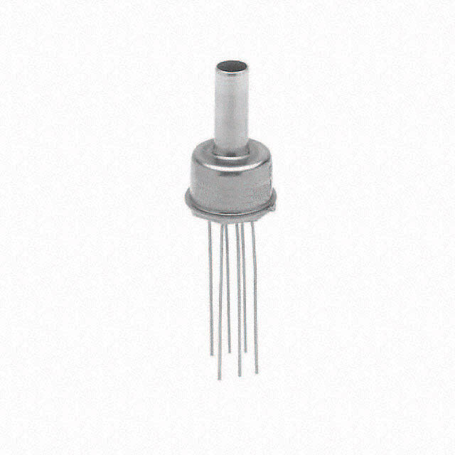
MS5540C Miniature Barometer Module APPLICATION INFORMATION GENERAL The advantage for this combination of a sensor with a directly adapted integrated circuit is to save other external components and to achieve very low power consumption. The main application field for this system includes portable devices with battery supply, but its high accuracy and resolution make it also suited for industrial and automotive applications. The possibility to compensate the sensor with software allows the user to adapt it to his particular application. Communication between the MS5540C and the widely available microcontrollers is realised over an easy-to-use 3-wire serial interface. Customers may select which microcontroller system to be used, and there are no specific standard interface cells required, which may be of interest for specially designed 4 Bit- microcontroller applications. CALIBRATION The MS5540C is factory calibrated. The calibration data is stored inside the 64 bit PROM memory. SOLDERING Please refer to the application note AN808 for all soldering issues. HUMIDITY, WATER PROTECTION The version MS5540-CM carries a metal protection cap filled with silicone gel for enhanced protection against humidity. The properties of this gel ensure function of the sensor even when in direct water contact. This feature can be useful for waterproof watches or other applications, where direct water contact cannot be avoided. Nevertheless the user should avoid drying of hard materials like for example salt particles on the silicone gel surface. In this case it is better to rinse with clean water afterwards. Special care has to be taken to not mechanically damage the gel. Damaged gel could lead to air entrapment and consequently to unstable sensor signal, especially if the damage is close to the sensor surface. The metal protection cap is fabricated of special anticorrosive stainless steel in order to avoid any corrosive battery effects inside the final product. The MS5540CM was qualified referring to the ISO Standard 22810 and can withstand a pressure of 10 bar in salt water. For underwater operations as specified in ISO Standard 22810 it is important to seal the sensor with a rubber O- ring around the metal cap. Any salt water coming to the contact side (ceramic and pads) of the sensor could lead to permanent damage. LIGHT SENSITIVITY The MS5540C is protected against sunlight by a layer of white gel. It is, however, important to note that the sensor may still be slightly sensitive to sunlight, especially to infrared light sources. This is due to the strong photo effect of silicon. As the effect is reversible there will be no damage, but the user has to take care that in the final product the sensor cannot be exposed to direct light during operation. This can be achieved for instance by placing mechanical parts with holes in such that light cannot pass. CONNECTION TO PCB The package outline of the module allows the use of a flexible PCB to connect it. This can be important for applications in watches and other special devices, and will also reduce mechanical stress on the device. For applications subjected to mechanical shock, it is recommended to enhance the mechanical reliability of the solder junctions by covering the rim or the corners of MS5540C's ceramic substrate with glue or Globtop-like material. SENSOR SOLUTIONS ///MS5540C 08/2017 Page 14
MS5540C Miniature Barometer Module DECOUPLING CAPACITOR Particular care must be taken when connecting the device to power supply. A 47 F tantalum capacitor must be placed as close as possible of the MS5540C's VDD pin. This capacitor will stabilize the power supply during data conversion and thus, provide the highest possible accuracy. APPLICATION EXAMPLE: ALTIMETER SYSTEM USING MS5540C MS5540C is a circuit that can be used in connection with a microcontroller in diving computer applications. It is designed for low-voltage systems with a supply voltage of 3V, particularly in battery applications. The MS5540C is optimised for low current consumption as the AD-converter clock (MCLK) can use the 32.768 kHz frequency of a standard watch crystal, which is supplied in most portable watch systems. For applications in altimeter systems MEAS Switzerland can deliver a simple formula to calculate the altitude, based on a linear interpolation, where the number of interpolation points influences the accuracy of the formula. 3V-Battery LCD-Display VDD XTAL1 32.768 kHz MS5540C VDD T4a7nµtFa l XTAL2 MCLK Keypad DIN DOUT 4/8bit-Microcontroller SCLK GND GND EEPROM optional Figure 7: Demonstration of MS5540C in a mobile altimeter SENSOR SOLUTIONS ///MS5540C 08/2017 Page 15
MS5540C Miniature Barometer Module PIN CONFIGURATION Fig. 2: Pin configuration of MS5540C Pin Name Pin Type Function SCLK 1 I Serial data clock GND 2 G Ground PV (1) 3 N Negative programming voltage PEN (1) 4 I Programming enable VDD 5 P Positive supply voltage MCLK 6 I Master clock (32.768 kHz) DIN 7 I Serial data input DOUT 8 O Serial data output NOTE 1) Pin 3 (PV) and Pin 4 (PEN) are only used by the manufacturer for calibration purposes and should not be connected. RECOMMENDED PAD LAYOUT Pad layout for bottom side of MS5540C soldered onto printed circuit board. Fig. 8: Layout for bottom side SENSOR SOLUTIONS ///MS5540C 08/2017 Page 16
MS5540C Miniature Barometer Module DEVICE PACKAGE OUTLINES Fig. 9: Device package outlines of MS5540-C SENSOR SOLUTIONS ///MS5540C 08/2017 Page 17
MS5540C Miniature Barometer Module SHIPPING PACKAGE Tube Tape & reel SENSOR SOLUTIONS ///MS5540C 08/2017 Page 18
MS5540C Miniature Barometer Module ASSEMBLY MECHANICAL STRESS It is recommended to avoid mechanical stress on the PCB on which the sensor is mounted. The thickness of the PCB should not be below 1.6 mm. A thicker PCB is stiffer creating less stress on the soldering contacts. For applications where mechanical stress cannot be avoided (for example ultrasound welding of the case or thin PCB’s in watches) please fix the sensor with drops of low stress epoxy (for example Hysol FP-4401). MOUNTING The MS5540C can be placed with automatic Pick & Place equipment using vacuum nozzles. It will not be damaged by the vacuum. Due to the low stress assembly the sensor does not show pressure hysteresis effects. Special care has to be taken to not touch the protective gel of the sensor during the assembly. The MS5540C can be mounted with the cap down or the cap looking upwards. In both cases it is important to solder all contact pads. The Pins PEN and PV shall be left open or connected to VDD. Do not connect the Pins PEN and PV to GND! SEALING WITH O-RING In products like outdoor watches the electronics must be protected against direct water or humidity. For those products the MS5540-CM provides the possibility to seal with an O-ring. The protective cap of the MS5540CM is made of special anticorrosive stainless steel with a polished surface. In addition to this the MS5540CM is filled with silicone gel covering the sensor and the bonding wires. The O-ring (or O-rings) shall be placed at the outer diameter of the metal cap. This method avoids mechanical stress because the sensor can move in vertical direction. CLEANING The MS5540C has been manufactured under cleanroom conditions. Each device has been inspected for the homogeneity and the cleanness of the silicone gel. It is therefore recommended to assemble the sensor under class 10’000 or better conditions. Should this not be possible, it is recommended to protect the sensor opening during assembly from entering particles and dust. To avoid cleaning of the PCB, solder paste of type “no-clean” shall be used. Cleaning might damage the sensor! ESD PRECAUTIONS The electrical contact pads are protected against ESD up to 4 kV HBM (human body model). It is therefore essential to ground machines and personal properly during assembly and handling of the device. The MS5540C is shipped in antistatic transport boxes. Any test adapters or production transport boxes used during the assembly of the sensor shall be of an equivalent antistatic material. SENSOR SOLUTIONS ///MS5540C 08/2017 Page 19
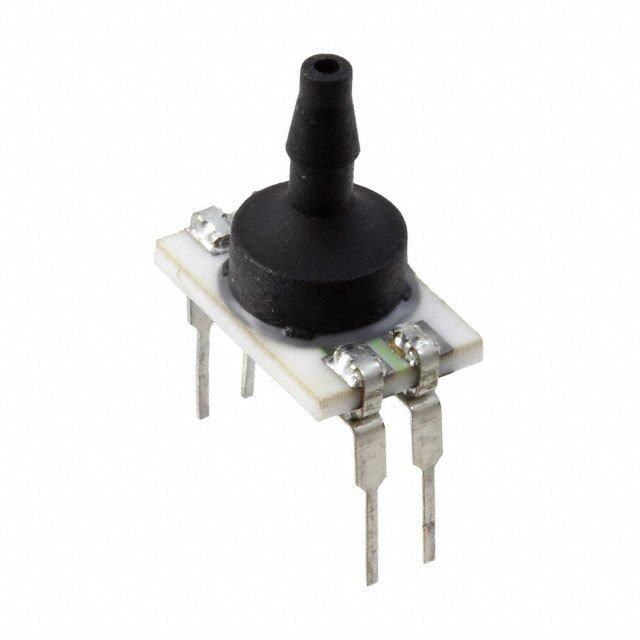
MS5540C Miniature Barometer Module ORDERING INFORMATION Part Number Description Delivery Form 325540009-00 MS5540-CM 1BAR White Gel Tube Tube 325540009-50 MS5540-CM 1BAR White Gel T&R Tape & Reel TOP-UP 325540009-10 MS5540-01BA 1BAR W Gel P-Caps Tray 325540009-60 MS5540-01BA 1BAR W Gel P-Caps T&R Tape & Reel 325540020-00 MS5540-HE 1BA White Gel HE Tube 325540020-50 MS5540-HE 1BA White Gel HE T&R Tape & Reel NORTH AMERICA EUROPE ASIA Measurement Specialties, Inc., Measurement Specialties (Europe), Ltd., Measurement Specialties (China) Ltd., a TE Connectivity company a TE Connectivity Company a TE Connectivity company Tel: 800-522-6752 Tel: 800-440-5100 Tel: 0400-820-6015 Email: customercare.frmt@te.com Email: customercare.bevx@te.com Email: customercare.shzn@te.com TE.com/sensorsolutions Measurement Specialties, Inc., a TE Connectivity company. Measurement Specialties, TE Connectivity, TE Connectivity (logo) and EVERY CONNECTION COUNTS are trademarks. All other logos, products and/or company names referred to herein might be trademarks of their respective owners. The information given herein, including drawings, illustrations and schematics which are intended for illustration purposes only, is believed to be reliable. However, TE Connectivity makes no warranties as to its accuracy or completeness and disclaims any liability in connection with its use. TE Connectivity‘s obligations shall only be as set forth in TE Connectivity‘s Standard Terms and Conditions of Sale for this product and in no case will TE Connectivity be liable for any incidental, indirect or consequential damages arising out of the sale, resale, use or misuse of the product. Users of TE Connectivity products should make their own evaluation to determine the suitability of each such product for the specific application. © 2015 TE Connectivity Ltd. family of companies All Rights Reserved. SENSOR SOLUTIONS ///MS5540C 08/2017 Page 20