
 Datasheet下载
- 型号: 27800
- 制造商: Parallax
- 库位|库存: xxxx|xxxx
- 要求:
| 数量阶梯 | 香港交货 | 国内含税 |
| +xxxx | $xxxx | ¥xxxx |
查看当月历史价格
查看今年历史价格
27800产品简介:
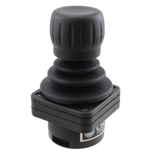
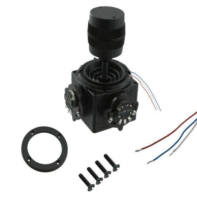
ICGOO电子元器件商城为您提供27800由Parallax设计生产,在icgoo商城现货销售,并且可以通过原厂、代理商等渠道进行代购。 27800价格参考。Parallax27800封装/规格:导航开关,操纵杆, 操纵杆,2 - 轴 模拟(电阻式) Output。您可以下载27800参考资料、Datasheet数据手册功能说明书,资料中有27800 详细功能的应用电路图电压和使用方法及教程。
Parallax Inc. 是一家专注于嵌入式系统和电子元件开发的公司,其产品广泛应用于教育、机器人、自动化和电子制作领域。型号为27800的导航开关/操纵杆模块是一种常用于人机交互控制的输入设备。

该产品的典型应用场景包括:

1. 教育与实验平台:广泛用于电子工程、机器人课程中,帮助学生学习模拟与数字信号处理、微控制器输入控制等知识。

2. 机器人控制:作为机器人遥控器或自主机器人上的手动操作接口,用于方向控制、机械臂操作等。

3. 无人机与遥控设备:用于小型无人机或遥控小车的操纵输入,提供X/Y轴方向控制和中心按钮确认功能。

4. 互动装置与游戏控制器:适用于DIY游戏手柄、交互式展览装置、电子玩具等需要方向输入和按钮操作的场景。

5. 工业与自动化设备:在小型自动化设备或调试工具中作为手动控制输入设备,用于菜单导航或参数调节。

该操纵杆模块具有结构紧凑、响应灵敏、易于集成等优点,适合与Arduino、Raspberry Pi、Propeller等开发平台配合使用。
| 参数 | 数值 |
| 产品目录 | |
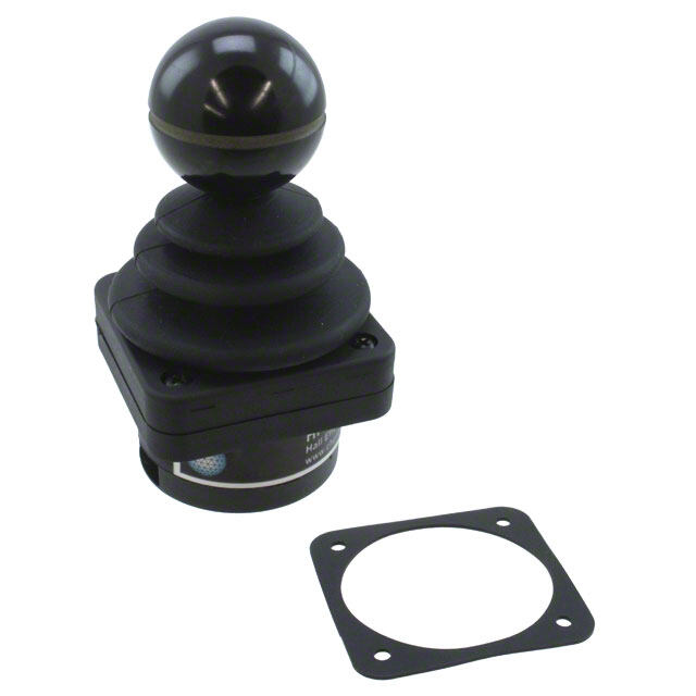
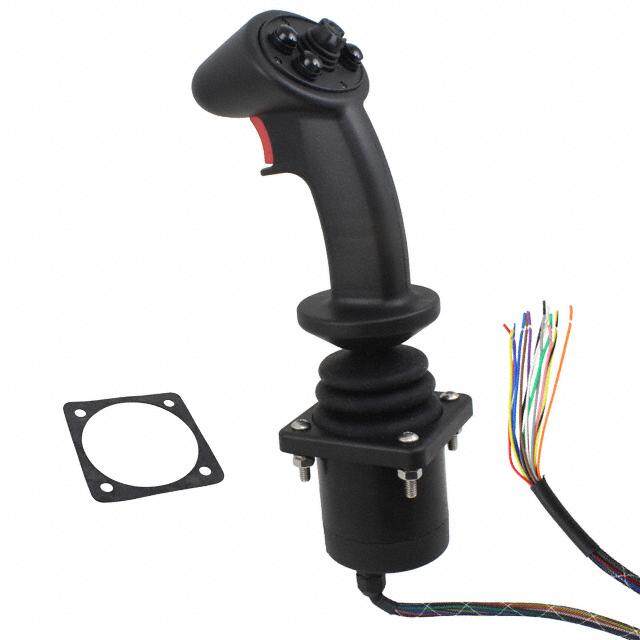
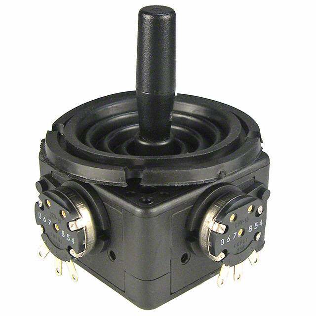
| 描述 | 2-AXIS JOYSTICK输入设备 2-Axis JoyStick |
| 产品分类 | |
| 品牌 | Parallax |
| 产品手册 | |
| 产品图片 |
|
| rohs | 符合RoHS无铅 / 符合限制有害物质指令(RoHS)规范要求 |
| 产品系列 | 输入设备,Parallax 27800- |
| mouser_ship_limit | 该产品可能需要其他文件才能进口到中国。 |
| 数据手册 | |
| 产品型号 | 27800 |
| 产品种类 | 输入设备 |
| 其它名称 | Q5761502 |
| 功率(W) | 0.01W |
| 包装 | 散装 |
| 单位重量 | 14.790 g |
| 商标 | Parallax |
| 安装类型 | 通孔 |
| 容差 | - |
| 封装/外壳 | 方形 - 1.202" 长 x 1.091" 宽 x 1.641" 高(30.54mm x 27.70mm x 41.67mm) |
| 旋转角度 | - |
| 标准包装 | 1 |
| 电阻(Ω) | 10k |
| 调节类型 | 顶部调节 |


- 商务部:美国ITC正式对集成电路等产品启动337调查
- 曝三星4nm工艺存在良率问题 高通将骁龙8 Gen1或转产台积电
- 太阳诱电将投资9.5亿元在常州建新厂生产MLCC 预计2023年完工
- 英特尔发布欧洲新工厂建设计划 深化IDM 2.0 战略
- 台积电先进制程称霸业界 有大客户加持明年业绩稳了
- 达到5530亿美元!SIA预计今年全球半导体销售额将创下新高
- 英特尔拟将自动驾驶子公司Mobileye上市 估值或超500亿美元
- 三星加码芯片和SET,合并消费电子和移动部门,撤换高东真等 CEO
- 三星电子宣布重大人事变动 还合并消费电子和移动部门
- 海关总署:前11个月进口集成电路产品价值2.52万亿元 增长14.8%


PDF Datasheet 数据手册内容提取
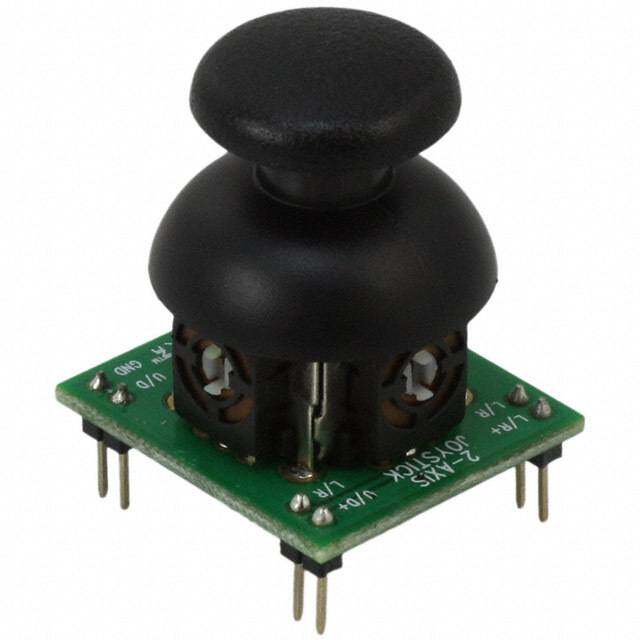
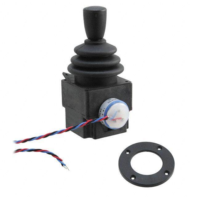
Web Site: www.parallax.com Office: (916) 624-8333 Forums: forums.parallax.com Fax: (916) 624-8003 Sales: sales@parallax.com Sales: (888) 512-1024 Technical: support@parallax.com Tech Support: (888) 997-8267 2-Axis Joystick (#27800) The 2-Axis Joystick can be used to add analog input to your next project. The 2-Axis Joystick contains two independent potentiometers (one per axis) that can be used as dual adjustable voltage dividers, providing 2-Axis analog input in a control stick form. The modular form-factor allows you to plug the 2-Axis Joystick directly into a breadboard for easy prototyping. The 2-Axis Joystick includes spring auto- return to center and a comfortable cup-type knob which gives the feel of a thumb-stick. Features (cid:1) Easy breadboard connection (cid:1) Two independent potentiometers with common ground (cid:1) Spring auto-return to center position (cid:1) Comfortable cup-type knob (cid:1) Compatible with most microcontrollers Key Specifications (cid:1) Power capability: 0.01W; 10 VDC maximum working voltage (cid:1) Interface: Dual 10 kΩ potentiometers with common ground (cid:1) Operating temperature: 32 to 158 °F (0 to 70 °C) (cid:1) Dimensions: 1.64" H x 1.40" L x 1.10" W (41.67 mm H x 35.56 mm L x 27.94 mm W) Application Ideas (cid:1) Camera Pan/Tilt Control (cid:1) Game Input/Control (cid:1) Robot Control (cid:1) Analog Input of Parameters Copyright © Parallax Inc. 2-Axis Joystick (#27800) v1.2 1/16/2012 Page 1 of 3
Quick Start Circuit This circuit works with the code below for the BASIC Stamp 2 to provide an RCTIME value for each axis that relates to the position of the joystick. In this manner the two potentiometers are providing a variable resistance for use with the RCTIME command. Caution: When using this circuit, do not use a resistor value less than 220 Ω and do not apply more than 5 VDC through this resistor to the L/R or U/D pins. For more information on how to measure resistance using the BASIC Stamp RCTIME command, please read Chapter#5 of What’s a Microcontroller? book, a free download at www.parallax.com/go/WAM. The PDF is also included in the BASIC Stamp Editor software’s Help file, which is a free download from www.parallax.com/basicstampsoftware. BASIC Stamp® 2 Program ' {$STAMP BS2} ' {$PBASIC 2.5} LR VAR Word UD VAR Word DO HIGH 4 PAUSE 2 RCTIME 4, 1, UD HIGH 11 PAUSE 2 RCTIME 11, 1, LR DEBUG HOME, "UD = ", DEC UD, CLREOL, CR, "LR = ", DEC LR, CLREOL PAUSE 50 LOOP Copyright © Parallax Inc. 2-Axis Joystick (#27800) v1.2 1/16/2012 Page 2 of 3
Advanced Circuit This circuit creates two voltage dividers referenced to VDD (in this case 5 V), using a 2-channel ADC (in this case the MCP3202) to read the voltages at the L/R and U/D pins using the code below. Caution: Do not apply voltage to the L/R+ or U/D+ pins that exceeds the I/O pin voltage rating of the device you connect to L/R or U/D, up to 10 VDC maximum. Ground<Analog voltage output at L/R and U/D<VDD. BASIC Stamp® 2 Program ' {$STAMP BS2} ' {$PBASIC 2.5} CS PIN 0 ' Chip Select (MCP3202.1) Clock PIN 1 ' Clock (MCP3202.7) DataIn PIN 2 ' --> Data Out (MCP3202.6) DataOut PIN 3 ' --> Data In (MCP3202.5) Cnts2Mv CON $0139 ' x 1.22 (To Millivolts) result0 VAR Word ' Conversion Result CH0 result1 VAR Word ' Conversion Result CH1 mVolts0 VAR Word ' Result0 --> mVolts mVolts1 VAR Word ' Result1 --> mVolts DEBUG CLS, "ADC CH 0:", CR, "Volts :", CR, "ADC CH 1:", CR, "Volts :" DO LOW CS ' Enable ADC SHIFTOUT DataOut, Clock, MSBFIRST, [%1101\4] ' Select CH0, Single-Ended SHIFTIN DataIn, Clock, MSBPOST, [result0\12] ' Read ADC HIGH CS ' Disable ADC mVolts0 = result0 */ Cnts2Mv ' Convert To Millivolts LOW CS ' Enable ADC SHIFTOUT DataOut, Clock, MSBFIRST, [%1111\4] ' Select CH1, Single-Ended SHIFTIN DataIn, Clock, MSBPOST, [result1\12] ' Read ADC HIGH CS ' Disable ADC mVolts1 = result1 */ Cnts2Mv ' Convert To Millivolts DEBUG HOME, CRSRXY, 9, 0, DEC result0, CLREOL, CRSRXY, 9, 1, DEC mVolts0 DIG 3, ".", DEC3 mVolts0, CRSRXY, 9, 2, DEC result1, CLREOL, CRSRXY, 9, 3, DEC mVolts1 DIG 3, ".", DEC3 mVolts1 PAUSE 100 LOOP Copyright © Parallax Inc. 2-Axis Joystick (#27800) v1.2 1/16/2012 Page 3 of 3