ICGOO在线商城 > 电路保护 > PTC 可复位保险丝 > 250S130VZR
 Datasheet下载
- 型号: 250S130VZR
- 制造商: Littelfuse
- 库位|库存: xxxx|xxxx
- 要求:
| 数量阶梯 | 香港交货 | 国内含税 |
| +xxxx | $xxxx | ¥xxxx |
查看当月历史价格
查看今年历史价格
250S130VZR产品简介:
ICGOO电子元器件商城为您提供250S130VZR由Littelfuse设计生产,在icgoo商城现货销售,并且可以通过原厂、代理商等渠道进行代购。 250S130VZR价格参考。Littelfuse250S130VZR封装/规格:PTC 可复位保险丝, 聚合物 PTC 自恢复保险丝 60V(250V Int) 130mA Ih 表面贴装 2-SMD。您可以下载250S130VZR参考资料、Datasheet数据手册功能说明书,资料中有250S130VZR 详细功能的应用电路图电压和使用方法及教程。
Littelfuse Inc. 是一家知名的电路保护解决方案提供商,其 250S130VZR 是一款属于 PTC(正温度系数)可复位保险丝的产品。该器件在电路中用于过流保护,能够在故障电流增大时自动增加电阻,限制电流流动,故障排除后可自动恢复,无需更换。

应用场景:

1. 电源适配器与充电器:用于保护便携式电子设备(如手机、平板、笔记本电脑)的充电电路,防止因短路或过载导致的损坏。

2. 工业控制设备:在PLC、变频器、伺服系统等设备中,为电路提供可靠且可复位的过流保护,提高设备运行稳定性。

3. 通信设备:用于路由器、交换机、基站模块等通信设备中,保护敏感电路免受异常电流影响。

4. 消费电子产品:例如智能音箱、游戏机、打印机等设备中,为内部电源或接口电路提供过流保护。

5. LED照明系统:在LED驱动电源中使用,防止因灯珠短路导致的电流异常,提升系统寿命。

6. 电动工具与小家电:用于保护电机或加热元件电路,在过载或堵转情况下提供保护。

250S130VZR 具有额定电压250V、保持电流约0.13A的特点,适用于低电流但需较高电压保护的交流或直流电路中。
| 参数 | 数值 |
| 产品目录 | |
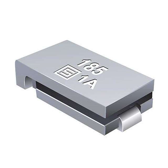
| 描述 | PTC RESET 250/60V VRT SMD 130MA可复位保险丝—PPTC 250/60V 1.3A PTC Vertical |
| 产品分类 | |
| 品牌 | Littelfuse |
| 产品手册 | |
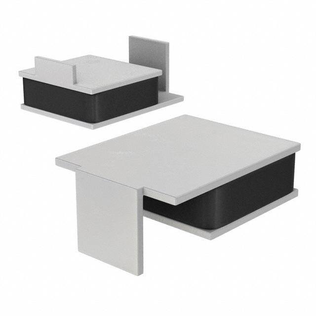
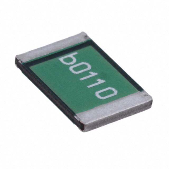
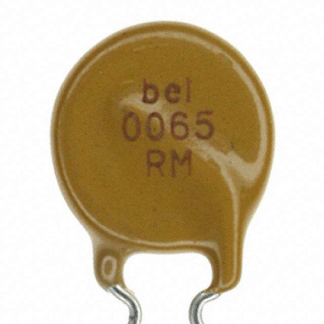
| 产品图片 |
|
| rohs | 符合RoHS无铅 / 符合限制有害物质指令(RoHS)规范要求 |
| 产品系列 | Littelfuse 250S130VZRPOLYFUSE® 250S |
| mouser_ship_limit | 该产品可能需要其他文件才能进口到中国。 |
| 数据手册 | |
| 产品型号 | 250S130VZR |
| R(最小/最大值) | 4.000 ~ 20.00 欧姆 |
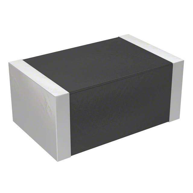
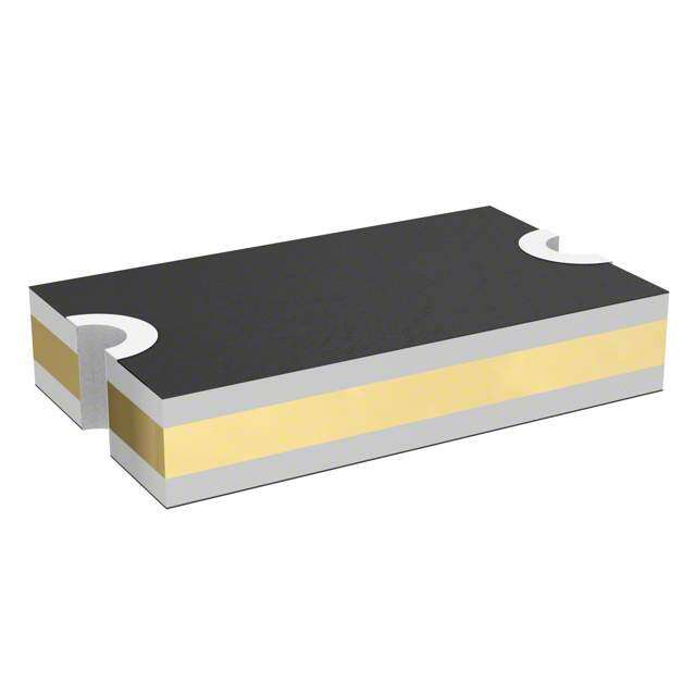
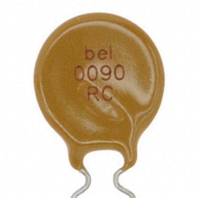
| 产品目录绘图 |
|
| 产品种类 | 可复位保险丝—PPTC |
| 其它名称 | F3778TR |
| 包装 | 带卷 (TR) |
| 商标 | Littelfuse |
| 封装 | Reel |
| 封装/外壳 | 2-SMD |
| 工厂包装数量 | 1200 |
| 最大电压 | 60 V |
| 标准包装 | 1,200 |
| 特色产品 | http://www.digikey.com/cn/zh/ph/Littelfuse/250s-series-polyfuse-high-voltage-smd.html |
| 电压-最大值 | 250V |
| 电流-保持(Ih)(最大值) | 130mA |
| 电流-最大值 | 3A |
| 电流-跳闸(It) | 260mA |
| 类型 | PolyFuse Resettable PTC |
| 跳闸时间 | 4s |
| 额定电流—最大值 | - |


- 商务部:美国ITC正式对集成电路等产品启动337调查
- 曝三星4nm工艺存在良率问题 高通将骁龙8 Gen1或转产台积电
- 太阳诱电将投资9.5亿元在常州建新厂生产MLCC 预计2023年完工
- 英特尔发布欧洲新工厂建设计划 深化IDM 2.0 战略
- 台积电先进制程称霸业界 有大客户加持明年业绩稳了
- 达到5530亿美元!SIA预计今年全球半导体销售额将创下新高
- 英特尔拟将自动驾驶子公司Mobileye上市 估值或超500亿美元
- 三星加码芯片和SET,合并消费电子和移动部门,撤换高东真等 CEO
- 三星电子宣布重大人事变动 还合并消费电子和移动部门
- 海关总署:前11个月进口集成电路产品价值2.52万亿元 增长14.8%


PDF Datasheet 数据手册内容提取
POLY-FUSE® Resettable PTCs Surface Mount > 250S Series 250S Series RoHS Description The 250S High Voltage Radial device is a Polymer-based PTC suitable to protect telephony equipment against lightining and power cross strikes. The 250S Series is fully compatible with telecommunications standards, and is offered in horizontal and new vertical surface mount package. Features • RoHS Compliant, • Helps meets ITU K.20, Directive 2002/95/EC K.21/Telcordia standards • Lead-Free & Halogen-Free • Excellent solder joint Agency Approvals • Low resistance inspectability • Compatible with telecom • High voltage AGENCY AGENCY FILE NUMBER standards E183209 Applications R50120008 • Customer Premises • LAN/WAN equipment Equipment (CPE) • Access equipment • Central Office (CO)/ telecom centers Additional Information Datasheet Resources SSaammpplleess Electrical Characteristics Agency Device Time to Trip at 1A Resistance I I V I P typ. Approvals Part Number Mounting hold trip max max d Layout (A) (A) (Vint /Vop) (A) (W) Typical Maximum R min R max R 1max (Sec.) (Sec.) (Ω) (Ω) (Ω) 250S130 0.13 0.26 250/60 3 1.2 0.9 4.0 4 13 20 – 250S130–RA 0.13 0.26 250/60 3 1.2 1.4 4.0 6.5 10 15 – Horizontal 250S130–RB 0.13 0.26 250/60 3 1.2 0.7 4.0 9 13 20 – 250S130–RC 0.13 0.26 250/60 3 1.2 1.1 4.0 7 11 17 – 250S130V Vertical 0.13 0.26 250/60 3 1.2 2.0 4.0 4 13 20 – I = Hold current: maximum current device will pass without tripping in 20°C still air. R = Minimum resistance of device in initial (un-soldered) state. hold min I = Trip current: minimum current at which the device will trip in 20°C still air. R = Maximum resistance of device in initial (un-soldered) state. trip max V = Maximum voltage the device can withstand without damage at rated current (I max) R = Maximum resistance of device at 20°C measured one hour after tripping. int 1max V = The device regular operation voltage Caution: Operation beyond the specified rating may result in damage and possible arcing op I = Maximum fault current device can withstand without damage at rated voltage (V ) and flame. max max P = Power dissipated from device when in the tripped state at 20°C still air. d WARNING • Users shall independently assess the suitability of these devices for each of their • Exposure to silicon-based oils, solvents, electrolytes, acids, and similar materials can applications adversely affect the performance of these PPTC devices • Operation of these devices beyond the stated maximum ratings could result in damage to • These devices undergo thermal expansion under fault conditions, and thus shall be the devices and lead to electrical arcing and/or fire provided with adequate space and be protected against mechanical stresses • These devices are intended to protect against the effects of temporary over-current or over- • Circuits with inductance may generate a voltage (L di/dt) above the rated voltage of the temperature conditions and are not intended to perform as protective devices where such PPTC device. conditions are expected to be repetitive or prolonged in duration © 2017 Littelfuse, Inc. Specifications are subject to change without notice. Revised: 03/22/17
POLY-FUSE® Resettable PTCs Surface Mount > 250S Series Temperature Rerating Ambient Operation Temperature -40°C -20°C 0°C 20°C 40°C 50°C 60°C 70°C 85°C Part Number Hold Current (A) 250S130 0.21 0.19 0.17 0.13 0.11 0.10 0.09 0.07 0.05 VV VV V VV 15V15V AAAAA/33A/24AA/16A/33AAA/6VA/12AA/24A/12AA/8VAA A/60 A/24 0.04A0.10A0.20A0.25A0.35A0.50A 0603L 0.10A0.20A0.35A0.50A0.75A1.00A1.10A 0805L 0.12A0.16A0.20A0.25A0.35A, 0.35A/0.50A, 0.50A/0.75A0.75A/13.2V1.1A1.5A1.75A2.0A 1206L 0.05A0.10A0.20A0.35A0.35A/300.50A0.50A/300.75A0.75A/241.10A1.50A1.50A/161.75A12.00A210L 10.10000.140000.200.500.750.750.751.101.101.101.251.251.501.501.501.601.601.602.002.601812L 0.30A0.50A0.75A/601.00A1.00A/331.50A2.00A 2016L 0.30A0.50A0.75A & 0.751.00A1.25A1.50A1.85A2.00A/24V2.50A2.60A & 2.603.00A/15V5.00A/16V 2920L Average Tim0.13Ae Current Curves 250S Tem2p00.e00rature Rerating Curve 100 100 100 100.00 10000 100 100 1000 160.00 % Time in Seconds 110 Time in Seconds 110 Time in Seconds 110 Time in Seconds 110..0000 Time in Seconds 101001000 Time in Seconds110 Time in Seconds 110 Time in Seconds11000 Percentage of rated current 12840000....00000000-40.00 0.00 40.00 80.00 120.00 Device Ambient Temperature ºC 1 0.1 0.1 0.1 0.10 0.1 0.1 1 Agency Specification Selection Guide For Telecom 0.1 and Networking Applications Product Lightning Power Cross 0.010.1 1 10 100 0.010.1 1 10 100 0.010.1 1 10 0.010.10 1.00 1100..0000 0.010.1 1 10 100 0.010.1 1 10 0.010.1 1 10 100 0.100.1 1 10 100 250S130 Current in Amperes Current in Amperes Current in Amperes Current in Amperes Current in Amperes Current in Amperes Current in Amperes Current in Amperes 250S130V ITU K.20/21/45 – ITU K.20/21/45 – 250S130-RA 1.5kV 10/700μs 230Vac, 10Ω 250S130-RB The average time current curves and Temperature Rerating curve performance is affected 0 by a number or variables, and these curves provided as guidance only. Customer must 250S130-RC 100000 0.10A0.20A0.35A0.50A0.75A1.00A 0805L OLD 100000 0.12A0.16A0.20A0.25A0.35A0.35A/15V0.50A0.50A/15V0.75A1.0A1.1A1.5A12.0A206L OLD 10000 0.05A0.10A0.20A0.35A0.50A0.75A1.10A1.50A1.75A2.00A 1210L OLD 100000 0.16A0.30A1.00A/33v1.00A1.50A2.00A 2016L OLD 100000 0.10A0.30A0.50A.75A .75A/61.00A1.25A1.50A1.85A2.00A/24V2.00A2.50A2.60A3.00A/15V3.00A 2920L verify the performance in their application. RSPeprgeoictoiefincc/taitoionn ApplicationA Gppuliidcaetion SDeleevcitcioen Access network equipment 250S130 South America/ Remote terminal 250S130V 10000 10000 1000 10000 10000 Asia/Europe Repeaters 250S130-RA s ITU K.45 WAN equipment 250S130-RB d n Cross –connect 250S130-RC o Time in Seconds101001000 Time in Seconds 101001000 Time in Sec 101100 Time in Seconds101001000 Time in Seconds101100000 SA S IoosTiuuUatt/hh EK uAA.2rmmo1peeerriiccaa// CPuhsPotIoOnnAmetTPCen SAesOraen/reDlIn SoeStaSts gtnDrtL, a ed amN,Plrp mIxOB oTplDiXd fnliinefiSae easqcnLmclyeucsasiserptdsemsmesnt 222222255555550000000SSSSSSS111111133333330000000V---VRRRCAB Asia/Europe T1/E1/J1 linecards 250S130-RA ITU K.20 ADSL/VDSL splitters 250S130-RB 1 1 0.1 1 1 CSU/DSU 250S130-RC 0.1 0.1 0.010.1 1 10 100 0.1 0.1 ©Sp 2e0c1ifi7c Laitttieolnfus saer,e I nscu.bject to change without notice. Current in Amperes Revised: 03/22/17 0.010.1 C1urrent in Amper1e0s 100 0.010.1 Cu1rrent in Amper1e0s 100 0.010.1 C1urrent in Amper1e0s 100 0.010.1 C1urrent in Amper1e0s 100
POLY-FUSE® Resettable PTCs Surface Mount > 250S Series Soldering Parameters Profile Feature Pb-Free Assembly t P T Average Ramp-Up Rate (T to T) 3°C/second max P Critical Zone S(max) P RRaammpp--uupp tL to tP Temperature Min (T ) 150°C s(min) T L t Pre Heat: Temperature Max (Ts(max)) 200°C TS(max) L Time (Min to Max) (ts) 60 – 180 secs eru RRaammpp--ddoown Time Maintained Temperature (TL) 217°C tar T PPrreehheeaatt e S(min) Above: Temperature (tL) 60 – 150 seconds pm tS e Peak / Classification Temperature (T) 260+0/-5 °C T P 25 Time within 5°C of actual peak 20 – 40 seconds time to peak temperature Time Temperature (t) p Ramp-down Rate 6°C/second max -- All temperature refer to topside of the package, measured on the package body surface Time 25°C to peak Temperature (TP) 8 minutes Max. -- If reflow temperature exceeds the recommended profile, devices may not meet the performance requirements -- Recommended reflow methods: IR, vapor phase oven, hot air oven, N environment 2 for lead -- Recommended maximum paste thickness is 0.25mm (0.010 inch) -- Devices can be cleaned using standard industry methods and solvents -- Devices can be reworked using the standard industry practices Physical Specifications Environmental Specifications Solder-Plated Copper (Solder Material: Operating/Storage Terminal Material -40°C to +85°C Matte Tin(Sn)) Temperature Meets EIA Specification RS186-9E, ANSI/ Maximum Device Surface Lead Solderability 125°C J-STD-002 Category 3. Temperature in Tripped State Passive Aging +85°C, 1000 hours Humidity Aging +85°C, 85%,R.H.,1000 hours MIL–STD–202, Method 107 Thermal Shock +125°C to -55°C 10 times Solvent Resistance MIL–STD–202, Method 215 Moisture Sensitivity Level Level 1, J–STD–020 © 2017 Littelfuse, Inc. Specifications are subject to change without notice. Revised: 03/22/17
POLY-FUSE® Resettable PTCs Surface Mount > 250S Series Dimensions C H B F D E A C G H G Soldering Pad Layout B F A B C D E F G H Part Inch mm Inch mm Inch Dmm InEch mm Inch mm Material Inch mm Inch mm Inch mm Number Max. Max. Max. AMax. Max. Max. Max. Max. Max. Max. G Max.GMax. Max. Max. Max. Max. 250S130 0.37 9.4 0.15 3.7 0.29 7.4 0.016 0.4 0.15 3.8 SSonld/Nerii/nCgu Pad L0a.y1o8ut 4.6 0.07 1.8 0.24 6.1 250S130–RA 0.37 9.4 0.15 3.7A 0.29 7.4 0CC.016 0.4 0.15 3.8 Sn/Ni/Cu 0.18 4.6 0.07 1.8 0.24 6.1 250S130–RB 0.37 9.4 0.15 3.7 0.29 7.4 0.016 0.4 0.15 3.8 Sn/Ni/CuI 0.18 4.6 0.07 1.8 0.24 6.1 250S130–RC 0.37 9.4 0.15 3.7 0.29 7.4 0.016 0.4 0.15 3.8 GSn/Ni/Cu 0.18 4.6 0.07 1.8 0.24 6.1 J B G A CC H H I D Soldering Pad Layout F E G J B G H H D Soldering Pad Layout F E A B C D E F G H I J Part Inch mm Inch mm Inch mm Inch mm Inch mm Inch mm Material Inch mm Inch mm Inch mm Inch mm Number Max. Max. Max. Max. Max. Max. Max. Max. Max. Max. Max. Max. Max. Max. Max. Max. Max. Max. Max. Max. 250S130V .24 6.1 .27 6.9 .13 3.2 .04 1.6 .07 1.9 .09 2.3 Sn/Ni/Cu .09 2.3 .09 2.4 .25 6.4 .14 3.43 Part Ordering Number System 250 S 130 -RA D R PACKAGING STYLE R: Tape & Reel QUANTITY CODE: D=1500 Z=1200 OPTION CODE (BLANK) = Horizontal / 4-13Ω resistance range V = Vertical / 4-13Ω resistance range -RA = Horizontal / 6.5-10Ω resistance range -RB = Horizontal / 9-13Ω resistance range -RC = Horizontal / 7-11Ω resistance range I CURRENT CODE HOLD (Refer to Electrical Characteristics Table) SURFACE MOUNT PEAK VOLTAGE RATING Packaging I Packaging Quantity & Packaging Part Number Ordering Number hold I Code Quantity (A) hold Option Code 250S130 250S130DR 0.13 130 Tape and Reel 1500 DR 250S130V 250S130VZR 0.13 130 Tape and Reel 1200 ZR 250S130–RA 250S130–RADR 0.13 130 Tape and Reel 1500 DR 250S130–RB 250S130–RBDR 0.13 130 Tape and Reel 1500 DR 250S130–RC 250S130–RCDR 0.13 130 Tape and Reel 1500 DR © 2017 Littelfuse, Inc. Specifications are subject to change without notice. Revised: 03/22/17
POLY-FUSE® Resettable PTCs Surface Mount > 250S Series Tape and Reel Specifications TAPE SPECIFICATIONS: REEL DIMENSIONS: EIA-481-1 (mm) EIA-481-1 (mm) W 16 +/- 0.30 H 22.4 +/- 0.05 F 7.5 +/- 0.05 W 16.4 .0 +0/+2 E 1.75 +/- 0.10 D Ø60+0.5 1 D 1.5 +/- 0.05 F Ø13.0+/- 0.2 0 D 1.00(MIN) C Ø340+/- 1.0 1 P 4.00 +/- 0.10 H 11+/- 0.5 0 1 P 12.00 +/- 0.10 W 2.2+/- 0.5 1 1 P 2.00 +/- 0.05 W 3.0+0.5 2 2 A 6.9 +/- 0.10 W 4.0+0.5 0 3 B 9.6 +/- 0.10 W 5.5+0.5 0 4 T 0.4 +/- 0.10 max K 3.4 +/- 0.15 0 Leader Min. 300 Trailer Min. 300 Tape and Reel Diagram H P1 D0 P2 P0 E1 W4 W3 D C F W W2 F W T D2 W1 A0 K0 B0 H1 Disclaimer Notice - Information furnished is believed to be accurate and reliable. However, users should independently evaluate the suitability of and test each product selected for their own applications. Littelfuse products are not designed for, and may not be used in, all applications. Read complete Disclaimer Notice at www.littelfuse.com/disclaimer-electronics. © 2017 Littelfuse, Inc. Specifications are subject to change without notice. Revised: 03/22/17