ICGOO在线商城 > 电路保护 > PTC 可复位保险丝 > MF-FSMF020X-2
 Datasheet下载
- 型号: MF-FSMF020X-2
- 制造商: Bourns
- 库位|库存: xxxx|xxxx
- 要求:
| 数量阶梯 | 香港交货 | 国内含税 |
| +xxxx | $xxxx | ¥xxxx |
查看当月历史价格
查看今年历史价格
MF-FSMF020X-2产品简介:
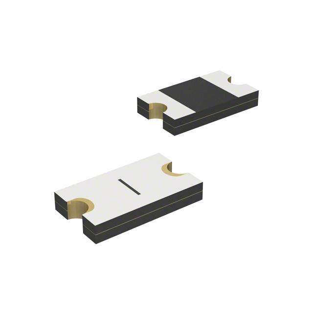
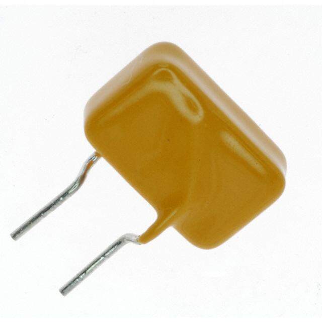
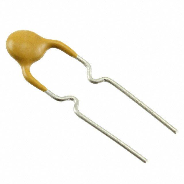
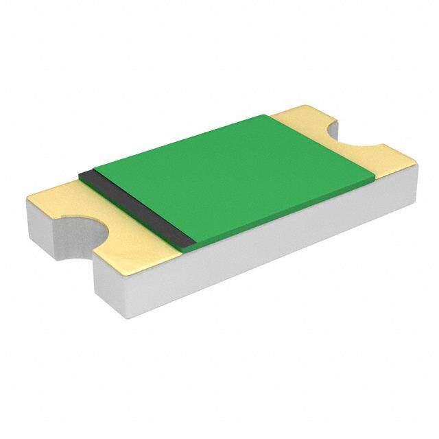
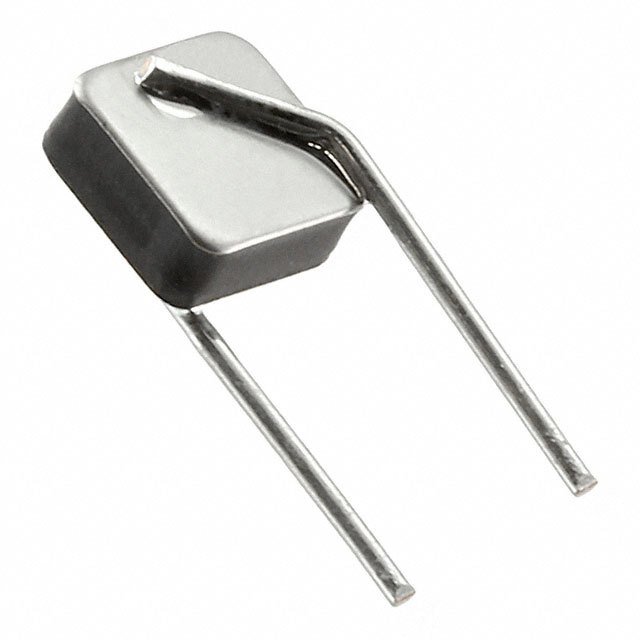
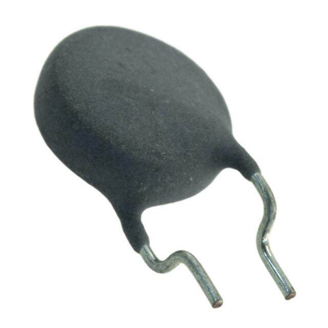
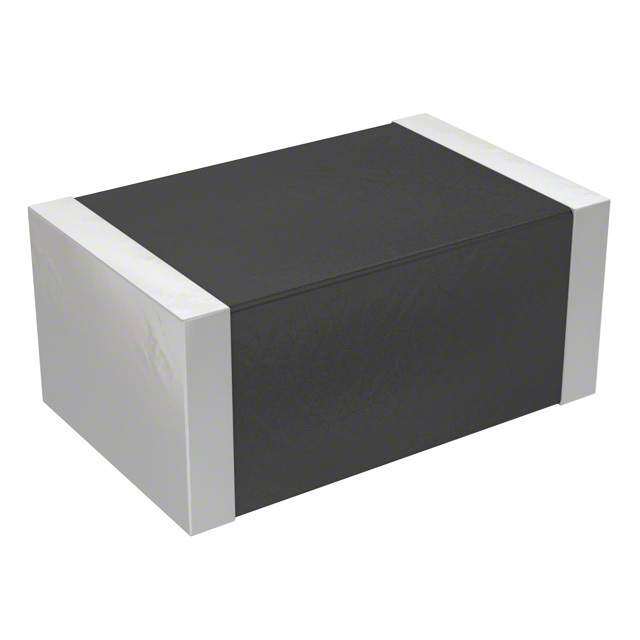
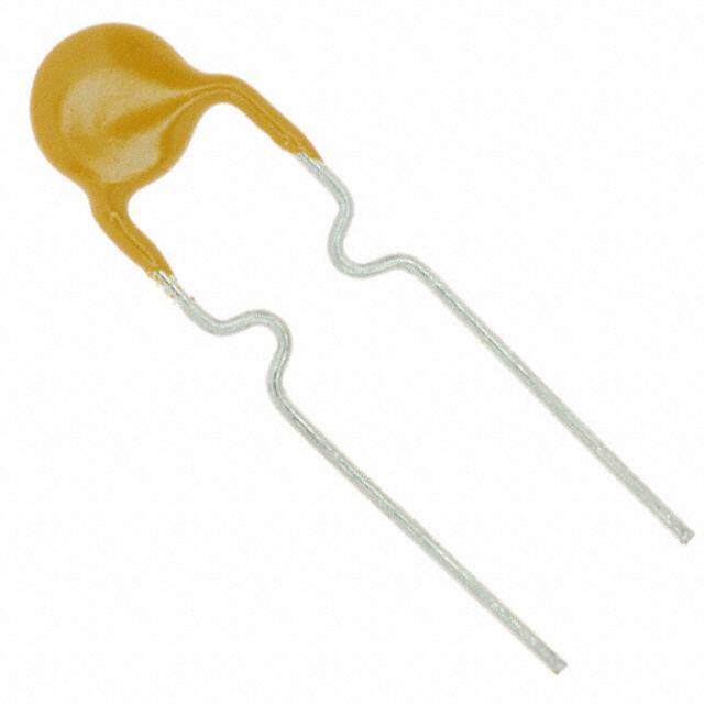
ICGOO电子元器件商城为您提供MF-FSMF020X-2由Bourns设计生产,在icgoo商城现货销售,并且可以通过原厂、代理商等渠道进行代购。 MF-FSMF020X-2价格参考¥1.45-¥1.45。BournsMF-FSMF020X-2封装/规格:PTC 可复位保险丝, 聚合物 PTC 自恢复保险丝 9V 200mA Ih 表面贴装 0603(1608 公制),凹陷。您可以下载MF-FSMF020X-2参考资料、Datasheet数据手册功能说明书,资料中有MF-FSMF020X-2 详细功能的应用电路图电压和使用方法及教程。
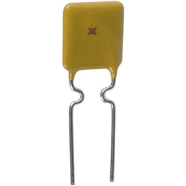
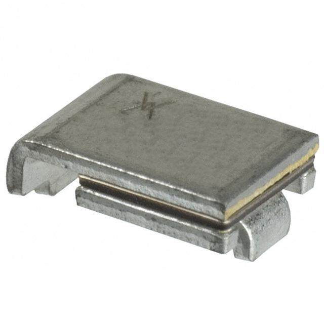
Bourns Inc.生产的MF-FSMF020X-2是一款PTC(正温度系数)可复位保险丝,广泛应用于各种电子设备中,以提供过流和过温保护。该型号的保险丝具有自恢复功能,能够在故障排除后自动恢复正常工作状态,无需更换。

 应用场景:

1. 消费类电子产品:
   - 智能手机和平板电脑:用于电池充电电路、USB接口等关键部位,防止因短路或过流导致的损坏。
   - 笔记本电脑:在电源适配器、电池管理模块中使用,确保设备在异常情况下不会因电流过大而受损。
   - 智能穿戴设备:如智能手表、健康手环等,保护内部电路免受过流和过温的影响。

2. 智能家居设备:
   - 智能插座和开关:内置PTC保险丝,防止因负载过大或短路引起的火灾风险。
   - 智能灯具:保护LED驱动电路,延长灯具的使用寿命。
   - 智能家电:如智能冰箱、洗衣机等,确保其控制电路的安全性和稳定性。

3. 通信设备:
   - 路由器和调制解调器:保护网络接口和电源模块,避免因外部干扰或内部故障导致的硬件损坏。
   - 交换机和服务器:在网络设备的关键节点上安装,确保数据传输的稳定性和安全性。

4. 工业控制和自动化系统:
   - PLC(可编程逻辑控制器):保护输入输出模块,防止因误操作或外部干扰引起的电路损坏。
   - 传感器和执行器:确保这些设备在恶劣环境下仍能正常工作,减少维护成本。

5. 汽车电子:
   - 车载娱乐系统:如音响、导航等,保护其电源电路,确保行车安全。
   - 车身控制系统:如车窗、门锁等,防止因电流波动引起的故障。

6. 医疗设备:
   - 便携式医疗仪器:如血糖仪、血压计等,确保设备在使用过程中不会因意外情况导致误读或损坏。
   - 大型医疗设备:如X光机、CT扫描仪等,保护其复杂的电路系统,确保诊断结果的准确性。

总之,MF-FSMF020X-2 PTC可复位保险丝凭借其可靠的保护性能和自恢复特性,在众多领域中发挥着重要作用,为各类电子设备提供了高效、稳定的过流和过温保护。
| 参数 | 数值 |
| 产品目录 | |
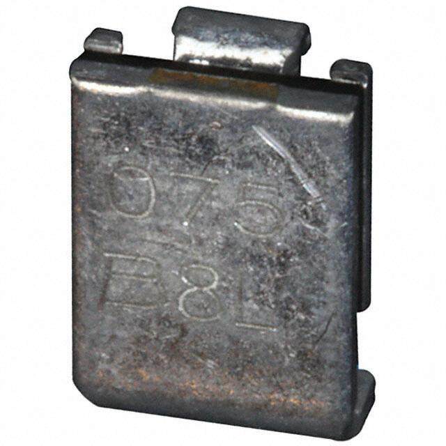
| 描述 | FUSE PTC RESET 200MA SMD 0603可复位保险丝—PPTC 9volts 40amps |
| 产品分类 | |
| 品牌 | Bourns Inc. |
| 产品手册 | |
| 产品图片 |
|
| rohs | 符合RoHS无铅 / 符合限制有害物质指令(RoHS)规范要求 |
| 产品系列 | Bourns MF-FSMF020X-2MF-FSMF |
| mouser_ship_limit | 该产品可能需要其他文件才能进口到中国。 |
| 数据手册 | |
| 产品型号 | MF-FSMF020X-2 |
| RoHS指令信息 | |
| R(最小/最大值) | 0.550 ~ 3.500 欧姆 |
| 产品目录绘图 |
|
| 产品目录页面 | |
| 产品种类 | 可复位保险丝—PPTC |
| 保持电流 | 0.2 A |
| 其它名称 | MF-FSMF020X-2DKR |
| 包装 | Digi-Reel® |
| 商标 | Bourns |
| 商标名 | Multifuse |
| 安装风格 | SMD/SMT |
| 封装 | Reel |
| 封装/外壳 | 0603(1608 公制),凹陷 |
| 尺寸 | 1.85 mm L x 1.05 mm W x 0.65 mm H |
| 工作温度范围 | - 40 C to + 85 C |
| 工具箱 | /product-detail/zh/PN-DESIGNKIT-11/PN-DESIGNKIT-11-ND/2334252 |
| 工厂包装数量 | 6000 |
| 最大电压 | 9 VDC |
| 标准包装 | 1 |
| 电压-最大值 | 9V |
| 电流-保持(Ih)(最大值) | 200mA |
| 电流-最大值 | 40A |
| 电流-跳闸(It) | 500mA |
| 电阻 | 3.5 Ohms |
| 端接类型 | SMD/SMT |
| 类型 | PTC Resettable Fuses |
| 系列 | MF-FSMF |
| 跳闸时间 | 0.6s |
| 跳闸电流 | 0.5 A |
| 额定电流—最大值 | 40 A |


X-2%20Side.jpg)


- 商务部:美国ITC正式对集成电路等产品启动337调查
- 曝三星4nm工艺存在良率问题 高通将骁龙8 Gen1或转产台积电
- 太阳诱电将投资9.5亿元在常州建新厂生产MLCC 预计2023年完工
- 英特尔发布欧洲新工厂建设计划 深化IDM 2.0 战略
- 台积电先进制程称霸业界 有大客户加持明年业绩稳了
- 达到5530亿美元!SIA预计今年全球半导体销售额将创下新高
- 英特尔拟将自动驾驶子公司Mobileye上市 估值或超500亿美元
- 三星加码芯片和SET,合并消费电子和移动部门,撤换高东真等 CEO
- 三星电子宣布重大人事变动 还合并消费电子和移动部门
- 海关总署:前11个月进口集成电路产品价值2.52万亿元 增长14.8%

PDF Datasheet 数据手册内容提取
Features Applications NT MPLIA ■ Compact design to save board space - ■ USB port protection HS CO 0603 footprint ■ HDMI 1.4 Source protection *Ro ■ Small size results in very fast time to react ■ PC motherboards - Plug and Play to fault events protection ■ Low profi le ■ Mobile phones - Battery and port ■ RoHS compliant* and halogen free** protection ■ Agency recognition: ■ PDAs / digital cameras MF-FSMF Series - PTC Resettable Fuses Electrical Characteristics Tripped Max. Time Ihold Itrip Resistance To Trip Power V max. I max. Dissipation Model Volts Amps Amperes Ohms Amperes Seconds Watts at 23 °C at 23 °C at 23 °C at 23 °C at 23 °C Hold Trip RMin. R1Max. Typ. MF-FSMF010X 15 40 0.10 0.30 0.900 6.000 0.50 1.00 0.5 MF-FSMF020X 9 40 0.20 0.50 0.550 3.500 1.00 0.60 0.5 MF-FSMF025X 6 40 0.25 0.75 0.20 1.400 8.00 0.10 0.5 MF-FSMF035X 6 40 0.35 0.75 0.200 1.400 8.00 0.10 0.5 MF-FSMF050X 6 40 0.50 1.00 0.100 0.800 8.00 0.10 0.5 Environmental Characteristics Operating Temperature .........................................-40 °C to +85 °C Maximum Device Surface Temperature in Tripped State ..................................................125 °C Passive Aging .......................................................+85 °C, 1000 hours ......................................±5 % typical resistance change Humidity Aging......................................................+85 °C, 85 % R.H. 1000 hours ....................±5 % typical resistance change Thermal Shock .....................................................+85 °C to -40 °C, 20 times ...........................±10 % typical resistance change Solvent Resistance ...............................................MIL-STD-202, Method 215 ..........................No change Vibration ...............................................................MIL-STD-883C, Method 2007.1, ..................No change ConditionA Test Procedures And Requirements For Model MF-FSMF Series Test Test Conditions Accept/Reject Criteria Visual/Mech. .........................................................Verify dimensions and materials ..................Per MF physical description Resistance ............................................................In still air @ 23 °C ........................................Rmin ≤ R ≤ R1max Time to Trip ...........................................................At specifi ed current, Vmax, 23 °C ................T ≤ max. time to trip (seconds) Hold Current .........................................................30 min. at Ihold ............................................No trip Trip Cycle Life .......................................................Vmax, Imax, 100 cycles ...............................No arcing or burning Trip Endurance .....................................................Vmax, 48 hours ............................................No arcing or burning Solderability ..........................................................ANSI/J-STD-002 ..........................................95 % min. coverage UL File Number ....................................................E174545 http://www.ul.com/ Follow link to Certifi cations, then UL File No., enter E174545 TÜV Certifi cate Number .......................................R 50171531 http://www.tuvdotcom.com/ Follow link to “other certifi cates”, enter File No. 50171531 Thermal Derating Chart - Ihold (Amps) Ambient Operating Temperature Model -40 °C -20 °C 0 °C 23 °C 40 °C 50 °C 60 °C 70 °C 85 °C MF-FSMF010X 0.13 0.12 0.11 0.10 0.08 0.07 0.06 0.05 0.03 MF-FSMF020X 0.27 0.25 0.23 0.20 0.17 0.14 0.12 0.10 0.07 MF-FSMF025X 0.32 0.29 0.27 0.25 0.21 0.18 0.16 0.14 0.10 MF-FSMF035X 0.47 0.41 0.38 0.35 0.29 0.26 0.24 0.20 0.14 MF-FSMF050X 0.67 0.59 0.54 0.50 0.41 0.37 0.34 0.29 0.20 * RoHS Directive 2002/95/EC Jan. 27, 2003 including annex and RoHS Recast 2011/65/EU June 8, 2011. **Bourns follows the prevailing definition of “halogen free” in the industry. Bourns considers a product to be “halogen free” if (a) the Bromine (Br) content is 900 ppm or less; (b) the Chlorine (Cl) content is 900 ppm or less; and (c) the total Bromine (Br) and Chlorine (Cl) content is 1500 ppm or less. Specifications are subject to change without notice. Users should verify actual device performance in their specific applications. The products described herein and this document are subject to specific legal disclaimers as set forth on the last page of this document, and at www.bourns.com/docs/legal/disclaimer.pdf.
Additional Applications ■ Automotive electronic control modules ■ Game console port protection MF-FSMF Series - PTC Resettable Fuses Product Dimensions A B C D Model Min. Max. Min. Max. Min. Max. Min. 1.45 1.85 0.65 1.05 0.30 0.65 0.20 MF-FSMF010X (0.057) (0.073) (0.026) (0.041) (0.012) (0.026) (0.008) 1.45 1.85 0.65 1.05 0.30 0.65 0.20 MF-FSMF020X (0.057) (0.073) (0.026) (0.041) (0.012) (0.026) (0.008) 1.45 1.85 0.65 1.05 0.30 0.65 0.20 MF-FSMF025X (0.057) (0.073) (0.026) (0.041) (0.012) (0.026) (0.008) 1.45 1.85 0.65 1.05 0.30 0.65 0.20 MF-FSMF035X (0.057) (0.073) (0.026) (0.041) (0.012) (0.026) (0.008) 1.45 1.85 0.65 1.05 0.65 1.00 0.20 MF-FSMF050X (0.057) (0.073) (0.026) (0.041) (0.026) (0.039) (0.008) Packaging: MF-FSMF010X = 5000 pcs. per reel; MM DIMENSIONS: MF-FSMF020X, MF-FSMF025X & MF-FSMF035X = 6000 pcs. per reel; (INCHES) MF-FSMF050X = 4000 pcs. per reel Top View Bottom View Side View Recommended Pad Layout Terminal material: Nickel/gold plated. A C Termination pad solderability: Standard Au fi nish: I 1.00 ± 0.05 Meets ANSI/J-STD-002 Category 2. B (.039 ± .002) Recommended Storage: 40 °C max./70 % RH max. D 0.70 ± 0.05 1.00 ± 0.05 (.028 ± .002) (.039 ± .002) How To Order MF - FSMF 020 X - 2 Solder Refl ow Recommendations Multifuse® Product Designator Preheating Soldering Cooling 300 Series FSMF = 0603 Surface Mount 250 Component Hold Current, Ihold erature (C)° 210500 MPau0clt1kifa0ug-s0ien5®g0 f r(e0e.1X0p -a n0s.5io0n A™m Dpse)sign p Packaged per EIA 481-1 em 100 -2 = Tape and Reel T 50 Typical Part Marking 0 PART IDENTIFICATION: MF-FSMF010X = II 160–220 10–20 120 I MMFF--FFSSMMFF002205XX == I+ MF-FSMF035X = (cid:129) Time (seconds) MF-FSMF050X = — Notes: BI-WEEKLY DATE CODE WILL APPEAR ON THE PACKAGING LABEL: • MF-FSMF models cannot be wave soldered. Please contact Bourns for hand soldering WEEK 1 AND 2 = A recommendations. WEEK 51 AND 52 = Z • If refl ow temperatures exceed the recommended profi le, devices may not meet the “freeXpansion Design” is a trademark of Bourns, Inc. performance requirements. Specifications are subject to change without notice. • Compatible with Pb and Pb-free solder refl ow profi les. Users should verify actual device performance • Excess solder may cause a short circuit, especially during hand soldering. Please refer to in their specific applications. the Multifuse® Polymer PTC Soldering Recommendation guidelines. The products described herein and this document are subject to specific legal disclaimers as set forth on the last page of this |document, and at www.bourns.com/docs/legal/disclaimer.pdf.
MF-FSMF Series - PTC Resettable Fuses Typical Time to Trip at 23 °C & MF010X MF020XMF025MXF 035X MF050X MF-FS MF-FSMF-FSMF-FS MF-FS 100 10 s) d n o 1 c e S p ( Tri o me t 0.1 Ti 0.01 0.001 0.1 1 10 Fault Current (Amps) The Time to Trip curves represent typical performance of a device in a simulated application environment. Actual performance in specifi c cus- tomer applications may differ from these values due to the infl uence of other variables. Asia-Pacifi c: Tel: +886-2 2562-4117 • Fax: +886-2 2562-4116 EMEA: Tel:+3688520390•Fax:+3688520211 The Americas: Tel: +1-951 781-5500 • Fax: +1-951 781-5700 www.bourns.com MF-FSMF SERIES, REV. I, 08/15 Specifications are subject to change without notice. Users should verify actual device performance in their specific applications. The products described herein and this document are subject to specific legal disclaimers as set forth on the last page of this document, and at www.bourns.com/docs/legal/disclaimer.pdf.
MF-FSMF Series Tape and Reel Specifi cations Product Dimensions MF-FSMF020X, MF-FSMF010X MF-FSMF025X, MF-FSMF035X MF-FSMF050X Tape Dimensions per EIA 481-1 per EIA 481-1 per EIA 481-1 8.0 ± 0.1 8.0 ± 0.1 8.0 ± 0.1 W (0.315 ± 0.004) (0.315 ± 0.004) (0.315 ± 0.004) 4.0 ± 0.1 4.0 ± 0.1 4.0 ± 0.1 P 0 (0.157 ± 0.004) (0.157 ± 0.004) (0.157 ± 0.004) 4.0 ± 0.05 4.0 ± 0.05 4.0 ± 0.05 P 1 (0.157 ± 0.002) (0.157 ± 0.002) (0.157 ± 0.002) 2.0 ± 0.05 2.0 ± 0.05 2.0 ± 0.05 P 2 (0.079 ± 0.002) (0.079 ± 0.002) (0.079 ± 0.002) 1.17 ± 0.05 1.17 ± 0.05 1.17 ± 0.05 A 0 (0.046 ± 0.002) (0.046 ± 0.002) (0.046 ± 0.002) 2.02 ± 0.05 2.02 ± 0.05 2.02 ± 0.05 B 0 (0.079 ± 0.002) (0.079 ± 0.002) (0.079 ± 0.002) 1.55 ± 0.05 1.55 ± 0.05 1.55 ± 0.05 D 0 (0.061 ± 0.002) (0.061 ± 0.002) (0.061 ± 0.002) 3.5 ± 0.05 3.5 ± 0.05 3.5 ± 0.05 F (0.138 + 0.002) (0.138 + 0.002) (0.138 + 0.002) 1.75 ± 0.1 1.75 ± 0.1 1.75 ± 0.1 E 1 (0.069 ± 0.004) (0.069 ± 0.004) (0.069 ± 0.004) 0.75 ± 0.05 0.60 ± 0.05 0.95 ± 0.05 T (0.030 ± 0.002) (0.024 ± 0.002) (0.037 ± 0.002) 40.0 ± 0.1 40.0 ± 0.1 40.0 ± 0.1 1 0 P0 (1.575 ± 0.004) (1.575 ± 0.004) (1.575 ± 0.004) Reel Dimensions 185 185 185 A max. (7.283) (7.283) (7.283) 50 50 50 N min. (1.97) (1.97) (1.97) 8.4 + 1.5/ -0.0 8.4 + 1.5/ -0.0 8.4 + 1.5/ -0.0 W 1 (0.331 + 0.059/-0) (0.331 + 0.059/-0) (0.331 + 0.059/-0) 14.4 14.4 14.4 W2 max. (0.567) (0.567) (0.567) 10 P0 W2(MEASURED AT HUB) T P0 D0 E1 F W A N(HUB DIA.) B 0 P2 P1 A0 W1(MEASURED AT HUB) MM DIMENSIONS: (INCHES) Specifications are subject to change without notice. Users should verify actual device performance in their specific applications. The products described herein and this document are subject to specific legal disclaimers as set forth on the last page of this document, and at www.bourns.com/docs/legal/disclaimer.pdf.
3B3o1u2rn -s ®2 Mmumlti fSuMseD® TPrPimTCm Rinegse Pttoatbelnet Fioumseester Application Notice • Users are responsible for independent and adequate evaluation of Bourns® Multifuse® Polymer PTC devices in the user’s application, including the PPTC device characteristics stated in the applicable data sheet. • Polymer PTC devices must not be allowed to operate beyond their stated maximum ratings. Operation in excess of such maximum ratings could result in damage to the PTC device and possibly lead to electrical arcing and/or fire. Circuits with inductance may generate a voltage above the rated voltage of the polymer PTC device and should be thoroughly evaluated within the user’s application during the PTC selection and qualification process. • Polymer PTC devices are intended to protect against adverse effects of temporary overcurrent or overtemperature conditions up to rated limits and are not intended to serve as protective devices where overcurrent or overvoltage conditions are expected to be repetitive or prolonged. • In normal operation, polymer PTC devices experience thermal expansion under fault conditions. Thus, a polymer PTC device must be protected against mechanical stress, and must be given adequate clearance within the user’s application to accommodate such thermal expansion. Rigid potting materials or fixed housings or coverings that do not provide adequate clearance should be thoroughly examined and tested by the user, as they may result in the malfunction of polymer PTC devices if the thermal expansion is inhibited. • Exposure to lubricants, silicon-based oils, solvents, gels, electrolytes, acids, and other related or similar materials may adversely affect the performance of polymer PTC devices. • Aggressive solvents may adversely affect the performance of polymer PTC devices. Conformal coating, encapsulating, potting, molding, and sealing materials may contain aggressive solvents including but not limited to xylene and toluene, which are known to cause adverse effects on the performance of polymer PTCs. Such aggressive solvents must be thoroughly cured or baked to ensure their complete removal from polymer PTCs to minimize the possible adverse effect on the device. • Recommended storage conditions should be followed at all times. Such conditions can be found on the applicable data sheet and on the Multifuse® Polymer PTC Moisture/Reflow Sensitivity Classification (MSL) note: https://www.bourns.com/docs/RoHS-MSL/msl_mf.pdf MFAN 12/18 Specifications are subject to change without notice. Users should verify actual device performance in their specific applications. The products described herein and this document are subject to specific legal disclaimers as set forth on the last page of this document, and at www.bourns.com/docs/legal/disclaimer.pdf.
Legal Disclaimer Notice This legal disclaimer applies to purchasers and users of Bourns® products manufactured by or on behalf of Bourns, Inc. and its affiliates (collectively, “Bourns”). Unless otherwise expressly indicated in writing, Bourns® products and data sheets relating thereto are subject to change without notice. Users should check for and obtain the latest relevant information and verify that such information is current and complete before placing orders for Bourns® products. The characteristics and parameters of a Bourns® product set forth in its data sheet are based on laboratory conditions, and statements regarding the suitability of products for certain types of applications are based on Bourns’ knowledge of typical requirements in generic applications. The characteristics and parameters of a Bourns® product in a user application may vary from the data sheet characteristics and parameters due to (i) the combination of the Bourns® product with other components in the user’s application, or (ii) the environment of the user application itself. The characteristics and parameters of a Bourns® product also can and do vary in different applications and actual performance may vary over time. Users should always verify the actual performance of the Bourns® product in their specific devices and applications, and make their own independent judgments regarding the amount of additional test margin to design into their device or application to compensate for differences between laboratory and real world conditions. Unless Bourns has explicitly designated an individual Bourns® product as meeting the requirements of a particular industry standard (e.g., ISO/TS 16949) or a particular qualification (e.g., UL listed or recognized), Bourns is not responsible for any failure of an individual Bourns® product to meet the requirements of such industry standard or particular qualification. Users of Bourns® products are responsible for ensuring compliance with safety-related requirements and standards applicable to their devices or applications. Bourns® products are not recommended, authorized or intended for use in nuclear, lifesaving, life-critical or life-sustaining applications, nor in any other applications where failure or malfunction may result in personal injury, death, or severe property or environmental damage. Unless expressly and specifically approved in writing by two authorized Bourns representatives on a case-by-case basis, use of any Bourns® products in such unauthorized applications might not be safe and thus is at the user’s sole risk. Life-critical applications include devices identified by the U.S. Food and Drug Administration as Class III devices and generally equivalent classifications outside of the United States. Bourns expressly identifies those Bourns® standard products that are suitable for use in automotive applications on such products’ data sheets in the section entitled “Applications.” Unless expressly and specifically approved in writing by two authorized Bourns representatives on a case-by-case basis, use of any other Bourns® standard products in an automotive application might not be safe and thus is not recommended, authorized or intended and is at the user’s sole risk. If Bourns expressly identifies a sub-category of automotive application in the data sheet for its standard products (such as infotainment or lighting), such identification means that Bourns has reviewed its standard product and has determined that if such Bourns® standard product is considered for potential use in automotive applications, it should only be used in such sub-category of automotive applications. Any reference to Bourns® standard product in the data sheet as compliant with the AEC-Q standard or “automotive grade” does not by itself mean that Bourns has approved such product for use in an automotive application. Bourns® standard products are not tested to comply with United States Federal Aviation Administration standards generally or any other generally equivalent governmental organization standard applicable to products designed or manufactured for use in aircraft or space applications. Bourns expressly identifies Bourns® standard products that are suitable for use in aircraft or space applications on such products’ data sheets in the section entitled “Applications.” Unless expressly and specifically approved in writing by two authorized Bourns representatives on a case-by-case basis, use of any other Bourns® standard product in an aircraft or space application might not be safe and thus is not recommended, authorized or intended and is at the user’s sole risk. The use and level of testing applicable to Bourns® custom products shall be negotiated on a case-by-case basis by Bourns and the user for which such Bourns® custom products are specially designed. Absent a written agreement between Bourns and the user regarding the use and level of such testing, the above provisions applicable to Bourns® standard products shall also apply to such Bourns® custom products. Users shall not sell, transfer, export or re-export any Bourns® products or technology for use in activities which involve the design, development, production, use or stockpiling of nuclear, chemical or biological weapons or missiles, nor shall they use Bourns® products or technology in any facility which engages in activities relating to such devices. The foregoing restrictions apply to all uses and applications that violate national or international prohibitions, including embargos or international regulations. Further, Bourns® products and Bourns technology and technical data may not under any circumstance be exported or re-exported to countries subject to international sanctions or embargoes. Bourns® products may not, without prior authorization from Bourns and/or the U.S. Government, be resold, transferred, or re-exported to any party not eligible to receive U.S. commodities, software, and technical data. To the maximum extent permitted by applicable law, Bourns disclaims (i) any and all liability for special, punitive, consequential, incidental or indirect damages or lost revenues or lost profits, and (ii) any and all implied warranties, including implied warranties of fitness for particular purpose, non-infringement and merchantability. For your convenience, copies of this Legal Disclaimer Notice with German, Spanish, Japanese, Traditional Chinese and Simplified Chinese bilingual versions are available at: Web Page: http://www.bourns.com/legal/disclaimers-terms-and-policies PDF: http://www.bourns.com/docs/Legal/disclaimer.pdf C1753 05/17/18R