ICGOO在线商城 > 电路保护 > PTC 可复位保险丝 > 250R180TF

 Datasheet下载
- 型号: 250R180TF
- 制造商: Littelfuse
- 库位|库存: xxxx|xxxx
- 要求:
| 数量阶梯 | 香港交货 | 国内含税 |
| +xxxx | $xxxx | ¥xxxx |
查看当月历史价格
查看今年历史价格
250R180TF产品简介:
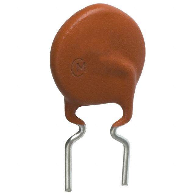
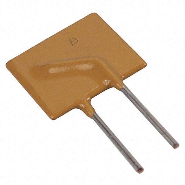
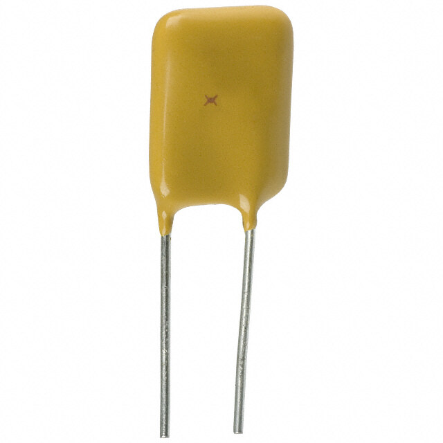
ICGOO电子元器件商城为您提供250R180TF由Littelfuse设计生产,在icgoo商城现货销售,并且可以通过原厂、代理商等渠道进行代购。 250R180TF价格参考。Littelfuse250R180TF封装/规格:PTC 可复位保险丝, 聚合物 PTC 自恢复保险丝 60V(250V Int) 180mA Ih 通孔 径向,圆片式。您可以下载250R180TF参考资料、Datasheet数据手册功能说明书,资料中有250R180TF 详细功能的应用电路图电压和使用方法及教程。
Littelfuse Inc.的250R180TF是一种PTC(正温度系数)可复位保险丝,广泛应用于需要过流和过温保护的电子设备中。该型号具有额定电压250V、保持电流1.8A的特点,适用于多种低压直流和交流电路。

其主要应用场景包括:

1. 消费电子产品:如手机充电器、电源适配器、蓝牙耳机等,用于防止因短路或过载导致的电路损坏。

2. 工业设备:用于PLC模块、传感器、工业控制电路中,提供可靠的电路保护,避免因故障导致系统损坏。

3. 通信设备:如路由器、交换机、光模块等,保护电源和数据接口免受过流影响。

4. 汽车电子:用于车载充电器、ECU模块、LED车灯等部件,提供符合汽车环境要求的稳定保护。

5. 家用电器:如电风扇、电热水壶、智能家电等,用于电机或电源模块的过流保护。

250R180TF具备自恢复功能,可在故障排除后自动复位,无需更换,提高了设备的可靠性和维护效率。同时其表面贴装封装(SMD)形式适用于自动化生产,适合现代电子产品的小型化与高密度设计需求。
| 参数 | 数值 |
| 产品目录 | |
| 描述 | PTC RESETBL 60V/250V .180A RAD可复位保险丝—PPTC PTC 60V/250V.180A POLY TELECOM |
| 产品分类 | |
| 品牌 | Littelfuse |
| 产品手册 | |
| 产品图片 |
|
| rohs | 符合RoHS无铅 / 符合限制有害物质指令(RoHS)规范要求 |
| 产品系列 | Littelfuse 250R180TFPOLYFUSE® 250R |
| mouser_ship_limit | 该产品可能需要其他文件才能进口到中国。 |
| 数据手册 | |
| 产品型号 | 250R180TF |
| R(最小/最大值) | 1.400 ~ 4.500 欧姆 |
| 产品种类 | 可复位保险丝—PPTC |
| 保持电流 | 0.18 A |
| 包装 | 散装 |
| 商标 | Littelfuse |
| 安装风格 | Through Hole |
| 封装 | Bulk |
| 封装/外壳 | 径向,圆盘 |
| 工作温度范围 | - 40 C to + 85 C |
| 工厂包装数量 | 200 |
| 最大电压 | 60 VDC |
| 标准包装 | 200 |
| 电压-最大值 | 250V |
| 电流-保持(Ih)(最大值) | 180mA |
| 电流-最大值 | 10A |
| 电流-跳闸(It) | 650mA |
| 电阻 | 4.5 Ohms |
| 端接类型 | Radial |
| 类型 | PolyFuse Resettable PTC |
| 系列 | 250R |
| 跳闸时间 | 20s |
| 跳闸电流 | 0.65 A |
| 额定电流—最大值 | 10 A |


- 商务部:美国ITC正式对集成电路等产品启动337调查
- 曝三星4nm工艺存在良率问题 高通将骁龙8 Gen1或转产台积电
- 太阳诱电将投资9.5亿元在常州建新厂生产MLCC 预计2023年完工
- 英特尔发布欧洲新工厂建设计划 深化IDM 2.0 战略
- 台积电先进制程称霸业界 有大客户加持明年业绩稳了
- 达到5530亿美元!SIA预计今年全球半导体销售额将创下新高
- 英特尔拟将自动驾驶子公司Mobileye上市 估值或超500亿美元
- 三星加码芯片和SET,合并消费电子和移动部门,撤换高东真等 CEO
- 三星电子宣布重大人事变动 还合并消费电子和移动部门
- 海关总署:前11个月进口集成电路产品价值2.52万亿元 增长14.8%


PDF Datasheet 数据手册内容提取
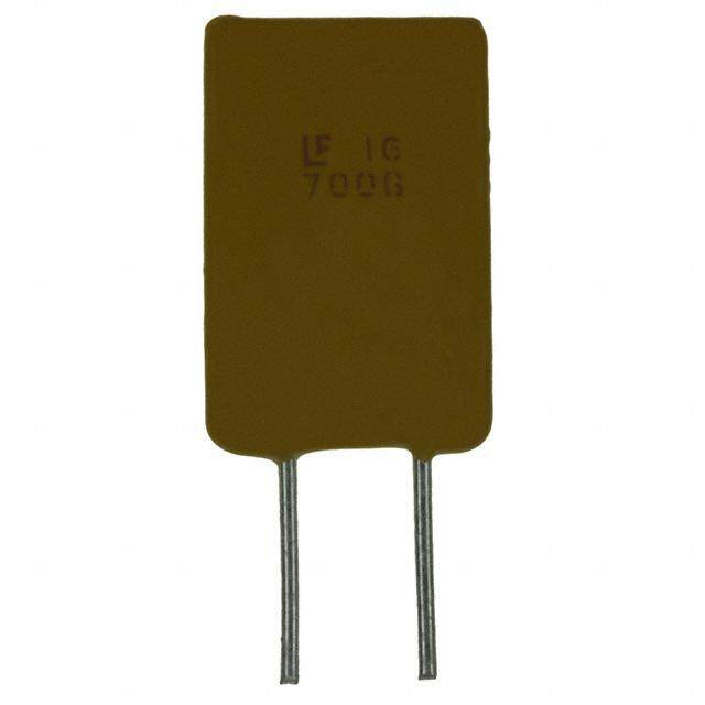
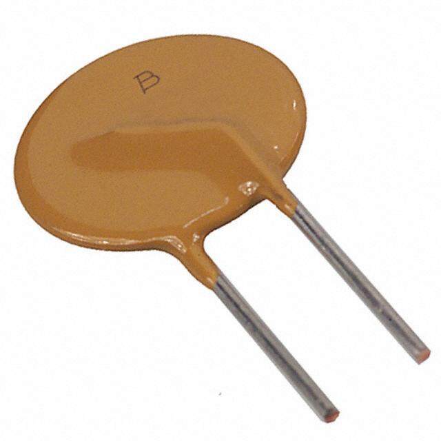
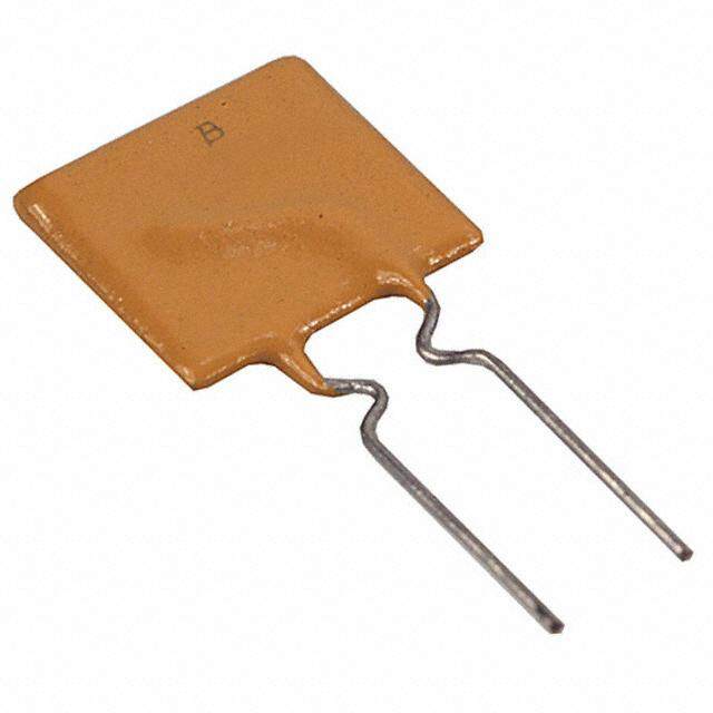
POLY-FUSE® Resettable PTCs Radial Leaded > 250R Series 250R Series RoHS * Description The 250R Series is designed to protect against short duration high voltage fault currents (power cross or power induction surge) typically found in telecom applications (250Vrms). The series can be used to help telecom networking equipment meet the protection requirements specified in ITU K.20 and K.21. Features • 0.08 – 0.18 hold current • Binned and sorted narrow range, 60VDC operating resistance ranges available voltage • RoHS compliant, Lead- Agency Approvals • 250VAC interrupt rating Free and Halogen-Free* • Fast time–to-trip AGENCY AGENCY FILE NUMBER Applications E183209 • Customer Premises • LAN/WAN equipment Equipment (CPE) • Access equipment R50120008 • Central Office (CO)/ telecom centers Electrical Characteristics Maximum Time Agency Part Number I hold I trip Vmax I max tPy pd. To Trip Resistance Approvals (A) (A) Vint / Vop (A) (W) Current Time R min R typ R 1max (A) (Sec.) (Ω) (Ω) (Ω) 250R080 0.08 0.16 250/60 3 1 0.35 4.0 14 22 33 X X 250R080T 0.08 0.16 250/60 3 1 0.35 4.0 15 22 33 X X 250R120 0.12 0.24 250/60 3 1 1 2.5 4 8 16 X X 250R120-RA 0.12 0.24 250/60 3 1 1 2.5 7 9 16 X X 250R120-RC 0.12 0.24 250/60 3 1 1 3.0 5.4 7.5 14 X X 250R120-RF 0.12 0.24 250/60 3 1 1 2.5 6 10.5 16 X X 250R120-R1 0.12 0.24 250/60 3 1 1 2.5 6 9 16 X X 250R120-R2 0.12 0.24 250/60 3 1 1 2.5 8 10.5 16 X X 250R120-R3 0.12 0.24 250/60 3 1 1 2.5 8 10 16 X X 250R120T 0.12 0.24 250/60 3 1 1 2.5 7 12 16 X X 250R145 0.145 0.29 250/60 3 1 1 2.5 3 6 14 X X 250R145-RA 0.145 0.29 250/60 3 1 1 2.5 3 5.5 12 X X 250R145-RB 0.145 0.29 250/60 3 1 1 2.5 4.5 6 14 X X 250R145T 0.145 0.29 250/60 3 1 1 2.5 5.4 7.5 14 X X 250R180 0.18 0.65 250/60 10 1.8 1 20 0.8 2.2 4 X X 250R180T 0.18 0.65 250/60 10 1.8 1 21 1.4 3.9 4.5 X X Items with T at end of part number = pre-tripped device. See Part Ordering Number System section of this data sheet for additional information. I = Hold current: maximum current device will pass without tripping in 20°C still air. R = Minimum resistance of device in initial (un-soldered) state. hold min I = Trip current: minimum current at which the device will trip in 20°C still air. R = Typical resistance of device in initial (un-soldered) state. trip typ V = Maximum voltage the device can withstand without damage at rated current (I max) R = Maximum resistance of device at 20°C measured one hour after tripping. int 1max V = The device regular operation voltage Caution: Operation beyond the specified rating may result in damage and possible arcing op I = Maximum fault current device can withstand without damage at rated voltage (V ) and flame. max max P = Power dissipated from device when in the tripped state at 20°C still air. d * Effective January 1, 2010, all 250R PTC products will be manufactured Halogen Free (HF). Existing Non-Halogen Free 250R PTC products may continue to be sold, until supplies are depleted. © 2017 Littelfuse, Inc. Specifications are subject to change without notice. Revised: 03/22/17
POLY-FUSE® Resettable PTCs Radial Leaded > 250R Series Temperature Rerating Ambient Operation Temperature -40°C -20°C 0°C 20°C 40°C 50°C 60°C 70°C 85°C Part Number Hold Current (A) 250R080 0.12 0.11 0.09 0.08 0.06 0.05 0.05 0.04 0.03 250R080T 0.12 0.11 0.09 0.08 0.06 0.05 0.05 0.04 0.03 250R120 0.18 0.16 0.14 0.12 0.10 0.09 0.08 0.06 0.05 250R120T 0.18 0.16 0.14 0.12 0.10 0.09 0.08 0.06 0.05 250R145 0.26 0.20 0.17 0.145 0.12 0.11 0.09 0.08 0.06 250R145T 0.26 0.20 0.17 0.145 0.12 0.11 0.09 0.08 0.06 250R180 0.28 0.23 0.21 0.18 0.16 0.13 0.10 0.11 0.083 250R180T 0.28 0.23 0.21 0.18 0.16 0.13 0.10 0.11 0.083 Average Time Current Curves Temperature Rerating Curve 170% 100000 150% nt 130% e 10000 urr d C 110% e at 1000 e of R 90% g m) centa 70% oh 100 Per 50% ce ( 30% n a esist 10 10%-40 -30 -20 -10 0 10 20 30 40 50 60 70 80 R Temperature (°C) 1 Note: Typical Temperature rerating curve, refer to table for derating data B 0.1 C A Additional Information D 0.01 0.11 10 100 Fault Current in Amperes Datasheet Resources SSaammpplleess The average time current curves and Temperature Rerating curve performance is affected by a number or variables, and these curves provided as guidance only. Customer must verify the performance in their application. Curve I hold Designation (A) A 0.18 B 0.145 C 0.12 D 0.80 © 2017 Littelfuse, Inc. Specifications are subject to change without notice. Revised: 03/22/17
POLY-FUSE® Resettable PTCs Radial Leaded > 250R Series Agency Specification Selection Guide For Telecom and Networking Applications Product Lightning Power Cross 250R120 ITU K.20/21/45 – 1.5kV 10/700μs ITU K.20/21/45 – 230Vac, 10Ω 250R145 ITU K.20/21/45 – 4kV 10/700μs* ITU K.20/21/45 – 600Vac, 600Ω ITU K.20/21/45 – 1.5kV 10/700μs ITU K.20/21/45 – 230Vac, 10Ω 250R180 ITU K.20/21/45 – 4kV 10/700μs* ITU K.20/21/45 – 600Vac, 600Ω Telcordia GR – 974 – 1.0kV 10/1000μs Telcordia GR – 974- 283Vac, 10A *Devices should be independently evaluated and tested for use in any specific application Protection Application Guide Region/Specification Application Device Selection 250R180 *Access network equipment 250R180T Remote terminal South America/Asia/Europe 250R145 Repeaters ITU K.45 250R145T WAN equipment 250R120 Cross –connect 250R120T Customer and IT equipment 250R180 Analog modems 250R180T South America/Asia/Europe ADSL, xDSL 250R145 ITU K.21 Phone sets, PBX systems 250R145T Internet appliances 250R120 POS terminals 250R120T 250R180 Central Office 250R180T POTS/ISDN linecards South America/Asia/Europe 250R145 T1/E1/J1 linecards ITU K.20 250R145T ADSL/VDSL splitters 250R120 CSU/DSU 250R120T North America Telcordia 250R180 GR-974 250R180T *Primary protection modules 250R145 MDF modules South America/Asia/Europe 250R145T Network interface ITU K.20 250R120 250R120T 250R180 North America Telcordia 250R180T GR-1089 *Intrabuilding communication systems 250R145 LAN, VOIP cards 250R145T South America/Asia/Europe Local loop handsets 250R120 ITU K.20 and K.21 250R120T LAN Intrabuilding power cross Protection 250R080 LAN equipment, IP phone *Resistance binned parts are recommended © 2017 Littelfuse, Inc. Specifications are subject to change without notice. Revised: 03/22/17
POLY-FUSE® Resettable PTCs Radial Leaded > 250R Series Soldering Parameters - Wave Soldering Condition Wave Soldering Peak Temp/ Duration Time 260°C < 5 Sec > 220°C 2 Sec ~ 20 Sec 260 Soldering Cooling 220 Preheat 140°C ~ 180°C 180 Sec ~ 210 Sec C) • S RNte2o ceroangmveirm oCneomnnddeeitndiot nsfoorld leearidn-gfr meee.thods: h0e°Ca~t 3e5le°Cm <e n7t0 %ovReHn or Temperature (° 116900 Preheating • Devices are designed to be wave soldered to the bottom side of the board. • Devices can be cleaned using standard industry methods 0 180 to 210 2 to 5 20-30 and solvents. Time(s) • This profile can be used for lead-free device Note: If soldering temperatures exceed the recommended profile, devices may not meet the performance requirements. Physical Specifications Environmental Specifications Operating/Storage Lead Material Tin-plated Copper -40°C to +85°C Temperature Soldering Solderability per MIL–STD–202, Maximum Device Surface 125°C Characteristics Method 208 Temperature in Tripped State Cured, flame retardant epoxy polymer Insulating Material Passive Aging 65°C/85°C, 1000 hours meets UL94V-0 requirements. Marked with 'LF', voltage, current rating, Device Labeling Humidity Aging +85°C, 85% R.H,.1000 hours and date code. MIL–STD–202, Method 107 Thermal Shock +125°C to -55°C 10 times Solvent Resistance MIL–STD–202, Method 215 Moisture Sesitivity Level Level 1, J–STD–020 Disclaimer Notice - Information furnished is believed to be accurate and reliable. However, users should independently evaluate the suitability of and test each product selected for their own applications. Littelfuse products are not designed for, and may not be used in, all applications. Read complete Disclaimer Notice at www.littelfuse.com/disclaimer-electronics. © 2017 Littelfuse, Inc. Specifications are subject to change without notice. Revised: 03/22/17
Figure 1 Figure 2 A C A C B B D D F F E E POLY-FUSE® Resettable PTCs Radial Leaded > 250R Series Dimensions Part Marking System Figure 1 Figure 2 A C A C Littelfuse 250 Voltage Rating Littelfuse 250 Voltage Rating Trademark 080 Current Rating Trademark 120 Current Rating XXXX Date Code XXXX Date Code (Contact Littelfuse (Contact Littelfuse B B finofro ardmdaittiioonna)l finofro ardmdaittiioonna)l D D E F E F Figure 1 Figure 2 A B C D E Physical Characteristics Part Number Figure Inches mm Inches mm Inches mm Inches mm Inches mm Lead (dia) Material Max. Max. Max. Max. Max. Max. Min. Min. Typ. Typ. Inches mm 250R080 1 0.23 5.8 0.39 9.9 0.18 4.6 0.19 4.7 0.20 5.1 0.026 0.65 Sn/Cu LTriattdeelfmusa2erk25500RR0X201X588X002X00T CD(VCouaolrttnreaet gCanecto tRRd Leaaittttiinnegglfu21se LTriattdeelfmusaerk 00..2273X21X52X00X 65..88CD(VCouaoltrtneraet gCanecto tRRd Leaaittttii00nnegglfu..s43e 39 91.19 00..1188 44..66 00..1199 44..77 00..2200 55..11 00..002266 00..6655 SSnn//CCuu for additional for additional information) information) 250R120-RA 2 0.27 6.8 0.43 11 0.18 4.6 0.19 4.7 0.20 5.1 0.026 0.65 Sn/Cu 250R120-RC 2 0.27 6.8 0.43 11 0.18 4.6 0.19 4.7 0.20 5.1 0.026 0.65 Sn/Cu 250R120-RF 2 0.27 6.8 0.43 11 0.18 4.6 0.19 4.7 0.20 5.1 0.026 0.65 Sn/Cu 250R120-R1 2 0.27 6.8 0.43 11 0.18 4.6 0.19 4.7 0.20 5.1 0.026 0.65 Sn/Cu 250R120-R2 2 0.27 6.8 0.43 11 0.18 4.6 0.19 4.7 0.20 5.1 0.026 0.65 Sn/Cu 250R120-R3 2 0.27 6.8 0.43 11 0.18 4.6 0.19 4.7 0.20 5.1 0.026 0.65 Sn/Cu 250R120T 2 0.27 6.8 0.43 11 0.18 4.6 0.19 4.7 0.20 5.1 0.026 0.65 Sn/Cu 250R145 2 0.27 6.8 0.43 11 0.18 4.6 0.19 4.7 0.20 5.1 0.026 0.65 Sn/Cu 250R145-RA 2 0.27 6.8 0.43 11 0.18 4.6 0.19 4.7 0.20 5.1 0.026 0.65 Sn/Cu 250R145-RB 2 0.27 6.8 0.43 11 0.18 4.6 0.19 4.7 0.20 5.1 0.026 0.65 Sn/Cu 250R145T 2 0.27 6.8 0.43 11 0.18 4.6 0.19 4.7 0.20 5.1 0.026 0.65 Sn/Cu 250R180 1 0.37 9.5 0.47 12 0.18 4.6 0.19 4.7 0.20 5.1 0.026 0.65 Sn/Cu 250R180T 1 0.37 9.5 0.47 12 0.18 4.6 0.19 4.7 0.20 5.1 0.026 0.65 Sn/Cu WARNING • Users shall independently assess the suitability of these devices for each of their applications • Operation of these devices beyond the stated maximum ratings could result in damage to the devices and lead to electrical arcing and/or fire • These devices are intended to protect against the effects of temporary over-current or over-temperature conditions and are not intended to perform as protective devices where such conditions are expected to be repetitive or prolonged in duration • Exposure to silicon-based oils, solvents, electrolytes, acids, and similar materials can adversely affect the performance of these PPTC devices • These devices undergo thermal expansion under fault conditions, and thus shall be provided with adequate space and be protected against mechanical stresses • Circuits with inductance may generate a voltage (L di/dt) above the rated voltage of the PPTC device. © 2017 Littelfuse, Inc. Specifications are subject to change without notice. Revised: 03/22/17
POLY-FUSE® Resettable PTCs Radial Leaded > 250R Series Part Ordering Number System 250 R 120 - RA Z R PACKAGING STYLE BLANK: Bulk R: Tape & Ammo QUANTITY CODE: F=200 M=1000 U=500 Z=1200 SERIES Rx: Resistance Range (x = A-Z or 1-9) [not applicable for all parts] T: PRE-TRIPPED DEVICE (OPTIONAL) I CURRENT CODE (Refer to Packaging or Electrical Characteristics tables) HOLD R: RADIAL PEAK VOLTAGE RATING Packaging Ordering I I Packaging Quantity & Part Number hold hold Quantity Number (A) Code Option Packaging Codes 250R080U Bulk 500 U 250R080 0.080 080 250R080ZR Tape and Ammo 1200 ZR 250R080TU Bulk 500 U 250R080T 0.080 080 250R080TZR Tape and Ammo 1200 ZR 250R120U Bulk 500 U 250R120 0.120 120 250R120ZR Tape and Ammo 1200 ZR 250R120-RAU Bulk 500 U 250R120-RA 0.120 120 250R120-RAZR Tape and Ammo 1200 ZR 250R120-RCU Bulk 500 U 250R120-RC 0.120 120 250R120-RCZR Tape and Ammo 1200 ZR 250R120-RFU Bulk 500 U 250R120-RF 0.120 120 250R120-RFZR Tape and Ammo 1200 ZR 250R120-R1U Bulk 500 U 250R120-R1 0.120 120 250R120-R1ZR Tape and Ammo 1200 ZR 250R120-R2U Bulk 500 U 250R120-R2 0.120 120 250R120-R2ZR Tape and Ammo 1200 ZR 250R120-R3U Bulk 500 U 250R120-R3 0.120 120 250R120-R3ZR Tape and Ammo 1200 ZR 250R120TU Bulk 500 U 250R120T 0.120 120 250R120TZR Tape and Ammo 1200 ZR 250R145U Bulk 500 U 250R145 0.145 145 250R145ZR Tape and Ammo 1200 ZR 250R145-RAU Bulk 500 U 250R145-RA 0.145 145 250R145-RAZR Tape and Ammo 1200 ZR 250R145-RBU Bulk 500 U 250R145-RB 0.145 145 250R145-RBZR Tape and Ammo 1200 ZR 250R145TU Bulk 500 U 250R145T 0.145 145 250R145TZR Tape and Ammo 1200 ZR 250R180F Bulk 200 F 250R180 0.180 180 250R180MR Tape and Ammo 1000 MR 250R180TF Bulk 200 F 250R180T 0.180 180 250R180TMR Tape and Ammo 1000 MR © 2017 Littelfuse, Inc. Specifications are subject to change without notice. Revised: 03/22/17
POLY-FUSE® Resettable PTCs Radial Leaded > 250R Series Tape and Ammo Specifications Devices taped using EIA468-B/IE286-2 standards. See table below and Figure 1 for details. Dimensions Dimension EIA Mark IEC Mark Dim. (mm) Tol. (mm) Carrier tape width W W 18 –0.5 / +1.0 Hold down tape width W W 11 min. 4 0 Top distance between tape edges W W 3 max. 6 2 Sprocket hole position W W 9 –0.5 / +0.75 5 1 Sprocket hole diameter* D D 4 –0.32 / +0.2 0 0 Abscissa to plane (straight lead) H H 18.5 –/+ 3.0 Abscissa to plane (kinked lead) H H 16 –/+ 0.5 0 0 Abscissa to top H H 32.2 max. 1 1 Overall width without lead protrusion C 42.5 max. 1 Overall width with lead protrusion C 43.2 max. 2 Lead protrusion L l 1.0 max. 1 1 Protrusion of cut out L L 11 max. Protrusion beyond hold–down tape l l Not specified 2 2 Sprocket hole pitch: 250R080–250R145 P P 12.7 –/+ 0.3 0 0 Sprocket hole pitch: 250R180 P P 25.4 –/+ 0.5 0 0 20 Pitch tolerance –/+ 1 consecutive. Device pitch: 250R080–250R145 12.7 Device pitch: 250R180 25.4 Tape thickness t t 0.9 max. Tape thickness with splice t 2.0 max. 1 Splice sprocket hole alignment 0 –/+ 0.3 Body lateral deviation Δh Δh 0 –/+ 1.0 Body tape plane deviation Δp Δp 0 –/+ 1.3 Ordinate to adjacent component lead* P P 3.81 –/+ 0.7 1 1 Lead spacing F F 5.1 –/+ 0.7 *Differs from EIA Specification Tape and Ammo Diagram ∆h ∆h Figure 1 ∆h ∆p Reference plane A H1 1 F H1 C1 H C 2 H L A B 0W W 5 4 W I 2 L1 P0 D0 Direction of unreeling Cross section A - B t © 2017 Littelfuse, Inc. Specifications are subject to change without notice. Revised: 03/22/17 Reel Upper side Tape Direction of unreeling Lower side w 1 Cross section w Optional shape: Circular or polygonal 2