ICGOO在线商城 > 电路保护 > PTC 可复位保险丝 > MF-R400-0-99
 Datasheet下载
- 型号: MF-R400-0-99
- 制造商: Bourns
- 库位|库存: xxxx|xxxx
- 要求:
| 数量阶梯 | 香港交货 | 国内含税 |
| +xxxx | $xxxx | ¥xxxx |
查看当月历史价格
查看今年历史价格
MF-R400-0-99产品简介:
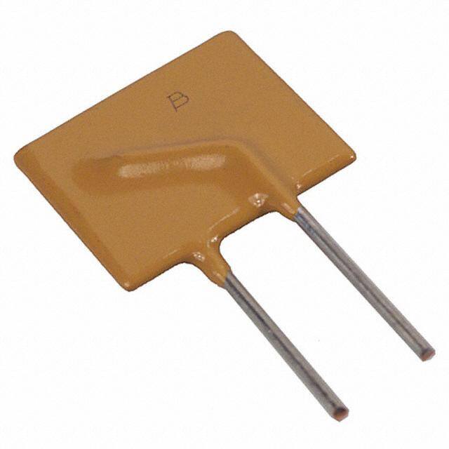
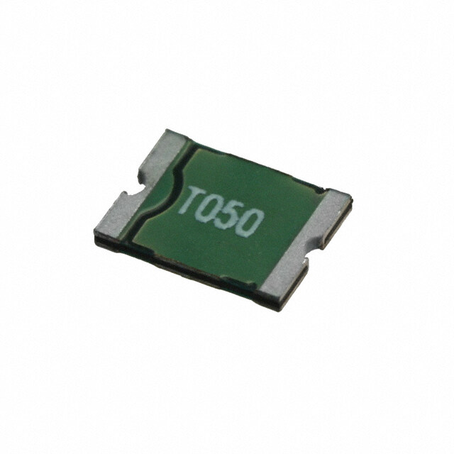
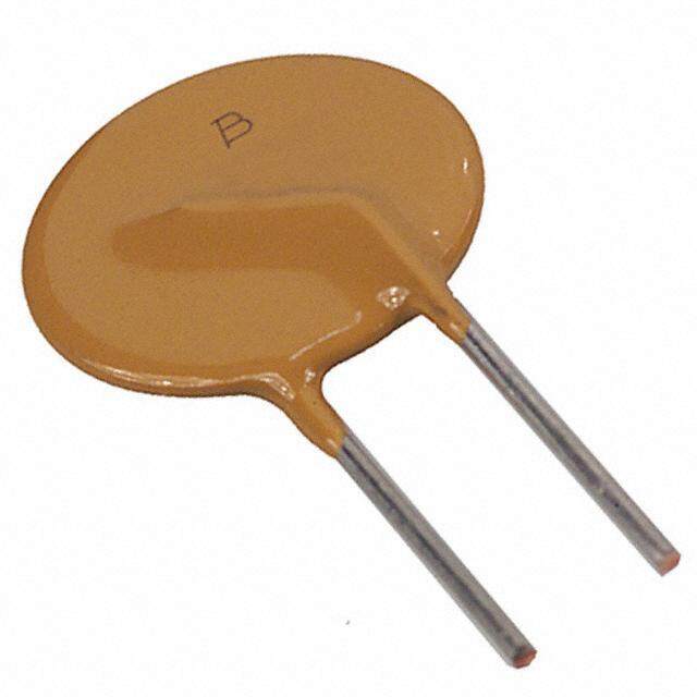
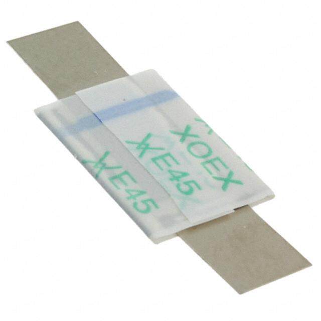
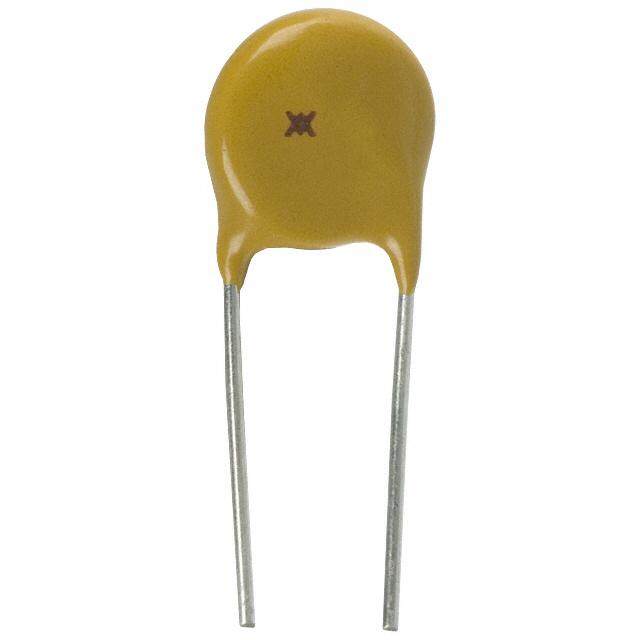
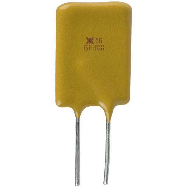
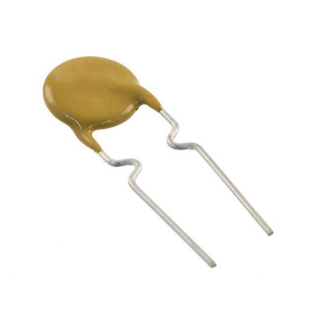
ICGOO电子元器件商城为您提供MF-R400-0-99由Bourns设计生产,在icgoo商城现货销售,并且可以通过原厂、代理商等渠道进行代购。 MF-R400-0-99价格参考。BournsMF-R400-0-99封装/规格:PTC 可复位保险丝, 聚合物 PTC 自恢复保险丝 30V 4A Ih 通孔 径向,圆片式。您可以下载MF-R400-0-99参考资料、Datasheet数据手册功能说明书,资料中有MF-R400-0-99 详细功能的应用电路图电压和使用方法及教程。
Bourns Inc. 生产的MF-R400-0-99是一款PTC(正温度系数热敏电阻)可复位保险丝,广泛应用于各种电子设备中,提供过流和过温保护。其主要应用场景如下:

1. 消费电子产品:如智能手机、平板电脑、笔记本电脑等便携式设备。这些设备内部电路复杂,容易因电流过大或温度过高而损坏。MF-R400-0-99能够在异常情况下自动断开电路,防止进一步损害,并在恢复正常后自动复位。

2. 电源适配器和充电器:用于保护电源适配器和充电器免受短路或过载的影响。该保险丝可以迅速响应异常情况,确保用户安全并延长设备寿命。

3. 家用电器:例如微波炉、电饭煲、电磁炉等厨房电器,以及洗衣机、空调等大型家电。这些设备通常需要长时间运行,容易出现过流或过温问题,使用PTC保险丝可以有效提高产品的可靠性和安全性。

4. 汽车电子系统:如车载音响、导航系统、倒车雷达等。在汽车环境中,电气系统可能会受到震动、温度变化等多种因素影响,PTC保险丝能够提供稳定可靠的保护。

5. 工业控制设备:包括PLC(可编程逻辑控制器)、传感器、电机驱动器等。工业环境中,设备往往需要连续工作,且环境条件较为恶劣,PTC保险丝能有效防止因电流波动或温度升高导致的故障。

6. 通信设备:如路由器、交换机、基站等网络设备。这些设备对稳定性和可靠性要求极高,PTC保险丝可以在不影响正常通信的情况下,及时切断异常电流,保障系统的正常运行。

总之,MF-R400-0-99作为一种高效可靠的保护元件,适用于多种场合,能够显著提升电子设备的安全性和稳定性。
| 参数 | 数值 |
| 产品目录 | |
| 描述 | FUSE PTC RESETTABLE可复位保险丝—PPTC 4A 30V |
| 产品分类 | |
| 品牌 | Bourns |
| 产品手册 | |
| 产品图片 |
|
| rohs | 符合RoHS无铅 / 符合限制有害物质指令(RoHS)规范要求 |
| 产品系列 | Bourns MF-R400-0-99MF-R |
| mouser_ship_limit | 该产品可能需要其他文件才能进口到中国。 |
| 数据手册 | |
| 产品型号 | MF-R400-0-99 |
| RoHS指令信息 | |
| R(最小/最大值) | 0.010 ~ 0.030 欧姆 |
| 产品培训模块 | http://www.digikey.cn/PTM/IndividualPTM.page?site=cn&lang=zhs&ptm=5252http://www.digikey.cn/PTM/IndividualPTM.page?site=cn&lang=zhs&ptm=4768 |
| 产品目录绘图 |
|
| 产品种类 | 可复位保险丝—PPTC |
| 保持电流 | 4 A |
| 其它名称 | MFR400099 |
| 包装 | 散装 |
| 商标 | Bourns |
| 商标名 | Multifuse |
| 安装风格 | Through Hole |
| 封装 | Bulk |
| 封装/外壳 | 径向 |
| 尺寸 | 24.8 mm L x 14.4 mm W x 3 mm H x 14.4 mm D |
| 工作温度范围 | - 40 C to + 85 C |
| 工厂包装数量 | 500 |
| 引线间隔 | 5.1 mm |
| 最大电压 | 30 VDC |
| 标准包装 | 500 |
| 电压-最大值 | 30V |
| 电流-保持(Ih)(最大值) | 4A |
| 电流-最大值 | 40A |
| 电流-跳闸(It) | 8A |
| 电阻 | 30 mOhms |
| 端接类型 | Radial |
| 类型 | PTC Resettable Fuses |
| 系列 | MF-R |
| 跳闸时间 | 12.7s |
| 跳闸电流 | 8 A |
| 零件号别名 | MF-R400 |
| 额定电流—最大值 | 40 A |


%20Series%20Side_3.0mm,20AWG.jpg)


PDF Datasheet 数据手册内容提取
Features Applications NT *RoHS CHOAML&POLIGEAN FREE 7R118100T nn RCinuasdrueiladalt, iLnflegaam mdeea drt eeDrtaiearvld imcaeneste etsp oUxLy 9p4oVly-m0 e r Asnul mpCpoolsymt apannudyte war shlo e&ared p ttehore ibpreeh eipsrra oals tleocwte vdo, litnacgleu dpionwg:er ** requirements n General electronics n RoHS compliant* and halogen free** n Automotive applications n Agency recognition: NT MPLIA O HS C MF-R Series - PTC Resettable Fuses Ro * Electrical Characteristics IholdREE Itrip Initial 1P Hoosut-rT (rRip1 ) Max. Time TPriopwpeerd Model VV molatsx. IA mmapxs. LEAAD Fmperes ReOsihsmtasn ce ReOsihsmtasn ce Amperetos TrSipeconds DisWsiaptatsti on at 23 °C at 23 °C at 23 °C at 23 °C at 23 °C at 23 °C Hold Trip Min. Max. Max. Typ. MF-R005 60 40 0.05 0.10 7.3 11.1 22.0 0.5 5.0 0.22 MF-R010 60 40 0.10 0.20 2.50 4.50 7.50 0.5 4.0 0.38 MF-R017 60 40 0.17 0.34 2.00 3.20 8.00 0.85 3.0 0.48 MMMMFFFF----RRRR000022340500 66660000 44440000 0000....22340500 0000....45680000 LVE1100EAR....DH S5075ISF O0062RCNEOSE MAPRLIE ANT*2110....89384566 4321....40120009 1112..2..0505 2233....2508 0000....44550505 MF-R050 60 40 0.50 1.00 R0o.41 0.77 1.17 2.5 4.0 0.75 MF-R065 60 40 0.65 1.30 0.27 0.48 0.72 3.25 5.3 0.90 MF-R075 60 40 0.75 1.50 0.18 0.40 0.60 3.75 6.3 0.90 MF-R090 60 40 0.90 1.80 0.14 0.31 0.47 4.5 7.2 1.00 MF-R090-0-9 30 40 0.90 1.80 0.07 0.12 0.22 4.5 5.9 0.60 MF-R110 30 40 1.10 2.20 0.10 0.18 0.27 5.5 6.6 0.70 MF-R135 30 40 1.35 2.70 0.065 0.115 0.17 6.75 7.3 0.80 MF-R160 30 40 1.60 3.20 0.055 0.105 0.15 8.0 8.0 0.90 MF-R185 30 40 1.85 3.70 0.040 0.07 0.11 9.25 8.7 1.00 MF-R250 30 40 2.50 5.00 0.025 0.048 0.07 12.5 10.3 1.20 MF-R250-0-10 30 40 2.50 5.00 0.025 0.048 0.07 12.5 10.3 1.20 MF-R300 30 40 3.00 6.00 0.020 0.05 0.08 15.0 10.8 2.00 MF-R400 30 40 4.00 8.00 0.010 0.03 0.05 20.0 12.7 2.50 MF-R500 30 40 5.00 10.00 0.010 0.03 0.05 25.0 14.5 3.00 MF-R600 30 40 6.00 12.00 0.005 0.02 0.04 30.0 16.0 3.50 MF-R700 30 40 7.00 14.00 0.005 0.02 0.03 35.0 17.5 3.80 MF-R800 30 40 8.00 16.00 0.005 0.02 0.03 40.0 18.8 4.00 MF-R900 30 40 9.00 18.00 0.005 0.01 0.02 40.0 20.0 4.20 MF-R1100 16 100 11.00 22.00 0.003 0.01 0.014 40.0 20.0 4.50 Environmental Characteristics Operating/Storage Temperature ...........................-40 °C to +85 °C Maximum Device Surface Temperature in Tripped State ................................................125 °C Passive Aging .......................................................+85 °C, 1000 hours ...............................................±5 % typical resistance change Humidity Aging......................................................+85 °C, 85 % R.H. 1000 hours .............................±5 % typical resistance change Thermal Shock .....................................................-40 °C to +85 °C, 10 times ....................................±10 % typical resistance change Solvent Resistance ...............................................MIL-STD-202, Method 215 ...................................No change Vibration ...............................................................MIL-STD-883C, Method 2007.1, ...........................No change Condition A Moisture Sensitivity Level .....................................1 ESD Classification (HBM).....................................6 Test Procedures And Requirements For Model MF-R Series Test Test Conditions Accept/Reject Criteria Visual/Mech. .........................................................Verify dimensions and materials ...........................Per MF physical description Resistance ............................................................In still air @ 23 °C .................................................Rmin ≤ R ≤ Rmax Time to Trip ...........................................................5 times Ihold, Vmax, 23 °C ...................................T ≤ max. time to trip (seconds) Hold Current .........................................................30 min. at Ihold .....................................................No trip Trip Cycle Life .......................................................Vmax, Imax, 100 cycles ........................................No arcing or burning Trip Endurance .....................................................Vmax, 48 hours .....................................................No arcing or burning UL File Number ..........................................................E174545 http://www.ul.com/ Follow link to Online Certificates Directory, then enter UL File No. E174545, or click here TÜV Certificate ...........................................................Certificate Number Available on Request, or click here * RoHS Directive 2002/95/EC Jan. 27, 2003 including annex and RoHS Recast 2011/65/EU June 8, 2011. ** Bourns follows the prevailing definition of “halogen free” in the industry. Bourns considers a product to be “halogen free” if (a) the Bromine (Br) content is 900 ppm or less; (b) the Chlorine (Cl) content is 900 ppm or less; and (c) the total Bromine (Br) and Chlorine (Cl) content is 1500 ppm or less. Specifications are subject to change without notice. Users should verify actual device performance in their specific applications. The products described herein and this document are subject to specific disclaimers as set forth on the last page of this document, and at www.bourns.com/legal/disclaimer.pdf.
Additional Features n Bulk packaging, tape and reel and Ammo-Pak available on most models MF-R Series - PTC Resettable Fuses Product Dimensions (see next page for outline drawing) Model A B C D E Physical Characteristics Max. Max. Nom. Tol. ± Min. Max. Style Lead Dia. Material 8.0 8.3 5.1 0.7 7.6 3.1 0.405 MF-R005 4 Sn/NiCu (0.315) (0.327) (0.201) (0.028) (0.299) (0.122) (0.016) 7.4 12.7 5.1 0.7 7.6 3.1 0.51 MF-R010 1 Sn/NiCu (0.291) (0.5) (0.201) (0.028) (0.299) (0.122) (0.020) 7.4 12.7 5.1 0.7 7.6 3.1 0.51 MF-R017 1 Sn/CuFe (0.291) (0.5) (0.201) (0.028) (0.299) (0.122) (0.020) 7.4 12.7 5.1 0.7 7.6 3.1 0.51 MF-R020 1 Sn/CuFe (0.291) (0.5) (0.201) (0.028) (0.299) (0.122) (0.020) 7.4 12.7 5.1 0.7 7.6 3.1 0.51 MF-R025 1 Sn/CuFe (0.291) (0.5) (0.201) (0.028) (0.299) (0.122) (0.020) 7.4 13.4 5.1 0.7 7.6 3.1 0.51 MF-R030 1 Sn/CuFe (0.291) (0.528) (0.201) (0.028) (0.299) (0.122) (0.020) 7.4 13.7 5.1 0.7 7.6 3.1 0.51 MF-R040 1 Sn/CuFe (0.291) (0.539) (0.201) (0.028) (0.299) (0.122) (0.020) 7.9 13.7 5.1 0.7 7.6 3.1 0.51 MF-R050 1 Sn/Cu (0.311) (0.539) (0.201) (0.028) (0.299) (0.122) (0.020) 9.7 15.2 5.1 0.7 7.6 3.1 0.51 MF-R065 1 Sn/Cu (0.382) (0.598) (0.201) (0.028) (0.299) (0.122) (0.020) 10.4 16.0 5.1 0.7 7.6 3.1 0.51 MF-R075 1 Sn/Cu (0.409) (0.630) (0.201) (0.028) (0.299) (0.122) (0.020) 11.7 16.7 5.1 0.7 7.6 3.1 0.51 MF-R090 1 Sn/Cu (0.461) (0.657) (0.201) (0.028) (0.299) (0.122) (0.020) 7.4 12.2 5.1 0.7 7.6 3.0 0.51 MF-R090-0-9 3 Sn/CuFe (0.291) (0.480) (0.201) (0.028) (0.299) (0.118) (0.020) 8.9 14.0 5.1 0.7 7.6 3.0 0.51 MF-R110 1 Sn/Cu (0.350) (0.551) (0.201) (0.028) (0.299) (0.118) (0.020) 8.9 18.9 5.1 0.7 7.6 3.0 0.51 MF-R135 1 Sn/Cu (0.350) (0.744) (0.201) (0.028) (0.299) (0.118) (0.020) 10.2 16.8 5.1 0.7 7.6 3.0 0.51 MF-R160 1 Sn/Cu (0.402) (0.661) (0.201) (0.028) (0.299) (0.118) (0.020) 12.0 18.4 5.1 0.7 7.6 3.0 0.51 MF-R185 1 Sn/Cu (0.472) (0.724) (0.201) (0.028) (0.299) (0.118) (0.020) 12.0 18.3 5.1 0.7 7.6 3.0 0.81 MF-R250 2 Sn/Cu (0.472) (0.720) (0.201) (0.028) (0.299) (0.118) (0.032) 12.0 18.3 5.1 0.7 7.6 3.0 0.51 MF-R250-0-10 3 Sn/CuFe (0.472) (0.720) (0.201) (0.028) (0.299) (0.118) (0.020) 12.0 18.3 5.1 0.7 7.6 3.0 0.81 MF-R300 2 Sn/Cu (0.472) (0.720) (0.201) (0.028) (0.299) (0.118) (0.032) 14.4 24.8 5.1 0.7 7.6 3.0 0.81 MF-R400 2 Sn/Cu (0.567) (0.976) (0.201) (0.028) (0.299) (0.118) (0.032) 17.4 24.9 10.2 0.7 7.6 3.0 0.81 MF-R500 2 Sn/Cu (0.685) (0.980) (0.402) (0.028) (0.299) (0.118) (0.032) 19.3 31.9 10.2 0.7 7.6 3.0 0.81 MF-R600 2 Sn/Cu (0.760) (1.256) (0.402) (0.028) (0.299) (0.118) (0.032) 22.1 29.8 10.2 0.7 7.6 3.0 0.81 MF-R700 2 Sn/Cu (0.870) (1.173) (0.402) (0.028) (0.299) (0.118) (0.032) 24.2 32.9 10.2 0.7 7.6 3.0 0.81 MF-R800 2 Sn/Cu (0.953) (1.295) (0.402) (0.028) (0.299) (0.118) (0.032) 24.2 32.9 10.2 0.7 7.6 3.0 0.81 MF-R900 2 Sn/Cu (0.953) (1.295) (0.402) (0.028) (0.299) (0.118) (0.032) 24.2 32.9 10.2 0.7 7.6 3.0 0.81 MF-R1100 2 Sn/Cu (0.953) (1.295) (0.402) (0.028) (0.299) (0.118) (0.032) Packaging options: 0.405 (26AWG) MM BULK: All models = 500 pcs. per bag 0.51 (24AWG) DIMENSIONS: (INCHES) 0.81 (20AWG) TAPE & REEL: MF-R005-MF-R160 12.7 mm device pitch = 3000 pcs. per reel MF-R185-MF-R400 25.4 mm device pitch = 1500 pcs. per reel MF-R500~MF-R1100 25.4 mm device pitch = 1000 pcs. per reel AMMO-PACK: MF-R005-MF-R160 12.7 mm device pitch = 2000 pcs. per pack MF-R185-MF-R400 25.4 mm device pitch = 1000 pcs. per pack MF-R500~MF-R1100 25.4 mm device pitch = 500 pcs. per pack Specifications are subject to change without notice. Users should verify actual device performance in their specific applications. The products described herein and this document are subject to specific disclaimers as set forth on the last page of this document, and at www.bourns.com/legal/disclaimer.pdf.
MF-R Series - PTC Resettable Fuses Product Dimensions (see previous page for dimensions) Style 1 Style 2 Style 3 Style 4 A E A E A E A E B B B B D C D D D C C C NOTE: Kinked lead option is NOTE: Also available with available for board standoff. straight leads. Contact Contact factory for details. factory for details. Thermal Derating Chart - Ihold / Itrip (Amps) Ambient Operating Temperature Model -40 ºC -20 ºC 0 ºC 23 ºC 40 ºC 50 ºC 60 ºC 70 ºC 85 ºC MF-R005 0.08 / 0.16 0.07 / 0.14 0.06 / 0.12 0.05 / 0.10 0.04 / 0.08 0.04 / 0.08 0.03 / 0.07 0.03 / 0.07 0.02 / 0.05 MF-R010 0.16 / 0.32 0.14 / 0.28 0.12 / 0.24 0.10 / 0.20 0.08 / 0.16 0.07 / 0.14 0.06 / 0.12 0.05 / 0.10 0.04 / 0.08 MF-R017 0.26 / 0.52 0.23 / 0.46 0.20 / 0.40 0.17 / 0.34 0.14 / 0.28 0.12 / 0.24 0.11 / 0.22 0.09 / 0.18 0.07 / 0.14 MF-R020 0.31 / 0.62 0.27 / 0.54 0.24 / 0.48 0.20 / 0.40 0.16 / 0.32 0.14 / 0.28 0.13 / 0.26 0.11 / 0.22 0.08 / 0.16 MF-R025 0.39 / 0.78 0.34 / 0.68 0.30 / 0.60 0.25 / 0.50 0.20 / 0.40 0.18 / 0.36 0.16 / 0.32 0.14 / 0.28 0.10 / 0.20 MF-R030 0.47 / 0.94 0.41 / 0.82 0.36 / 0.72 0.30 / 0.60 0.24 / 0.48 0.22 / 0.44 0.19 / 0.38 0.16 / 0.32 0.12 / 0.24 MF-R040 0.62 / 1.24 0.54 / 1.08 0.48 / 0.96 0.40 / 0.80 0.32 / 0.64 0.29 / 0.58 0.25 / 0.50 0.22 / 0.44 0.16 / 0.32 MF-R050 0.78 / 1.56 0.68 / 1.36 0.60 / 1.20 0.50 / 1.00 0.41 / 0.82 0.36 / 0.72 0.32 / 0.64 0.27 / 0.54 0.20 / 0.40 MF-R065 1.01 / 2.02 0.88 / 1.76 0.77 / 1.54 0.65 / 1.30 0.53 / 1.06 0.47 / 0.94 0.41 / 0.82 0.35 / 0.70 0.26 / 0.52 MF-R075 1.16 / 2.32 1.02 / 2.04 0.89 / 1.78 0.75 / 1.50 0.61 / 1.22 0.54 / 1.08 0.47 / 0.94 0.41 / 0.82 0.30 / 0.60 MF-R090 1.40 / 2.80 1.22 / 2.44 1.07 / 2.14 0.90 / 1.80 0.73 / 1.46 0.65 / 1.30 0.57 / 1.14 0.49 / 0.98 0.36 / 0.72 MF-R090-0-9 1.40 / 2.80 1.22 / 2.44 1.07 / 2.14 0.90 / 1.80 0.73 / 1.46 0.65 / 1.30 0.57 / 1.14 0.49 / 0.98 0.36 / 0.72 MF-R110 1.60 / 3.20 1.43 / 2.86 1.27 / 2.54 1.10 / 2.20 0.91 / 1.82 0.85 / 1.70 0.75 / 1.50 0.67 / 1.34 0.57 / 1.14 MF-R135 1.96 / 3.92 1.76 / 3.52 1.55 / 3.10 1.35 / 2.70 1.12 / 2.24 1.04 / 2.08 0.92 / 1.84 0.82 / 1.64 0.70 / 1.40 MF-R160 2.32 / 4.64 2.08 / 4.16 1.84 / 3.68 1.60 / 3.20 1.33 / 2.66 1.23 / 2.46 1.09 / 2.18 0.98 / 1.96 0.83 / 1.66 MF-R185 2.68 / 5.36 2.41 / 4.82 2.13 / 4.26 1.85 / 3.70 1.54 / 3.08 1.42 / 2.84 1.26 / 2.52 1.13 / 2.26 0.96 / 1.92 MF-R250 3.63 / 7.26 3.25 / 6.50 2.88 / 5.76 2.50 / 5.00 2.08 / 4.16 1.93 / 3.86 1.70 / 3.40 1.53 / 3.06 1.30 / 2.60 MF-R250-0-10 3.63 / 7.26 3.25 / 6.50 2.88 / 5.76 2.50 / 5.00 2.08 / 4.16 1.93 / 3.86 1.70 / 3.40 1.53 / 3.06 1.30 / 2.60 MF-R300 4.35 / 8.70 3.90 / 7.80 3.45 / 6.90 3.00 / 6.00 2.49 / 4.98 2.31 / 4.62 2.04 / 4.08 1.83 / 3.66 1.56 / 3.12 MF-R400 5.80 / 11.6 5.20 / 10.4 4.60 / 9.20 4.00 / 8.00 3.32 / 6.64 3.08 / 6.16 2.72 / 5.44 2.44 / 4.88 2.08 / 4.16 MF-R500 7.25 / 14.5 6.50 / 13.0 5.75 / 11.5 5.00 / 10.0 4.15 / 8.30 3.85 / 7.70 3.40 / 6.80 3.05 / 6.10 2.60 / 5.20 DIMENSIONS: MM MF-R600 8.70 / 17.4 7.80 / 15.6 6.90 / 13.8 6.00 / 12.0 4.98 / 9.96 4.62 / 9.24 4.08 / 8.16 3.66 / 7.32 3.12 / 6.24 (INCHES) MF-R700 10.1 / 20.3 9.10 / 18.2 8.05 / 16.1 7.00 / 14.0 5.81 / 11.6 5.39 / 10.7 4.76 / 9.52 4.27 / 9.44 3.64 / 7.28 MF-R800 11.6 / 23.2 10.4 / 20.8 9.20 / 18.4 8.00 / 16.0 6.64 / 13.2 6.16 / 12.3 5.44 / 10.8 4.88 / 9.76 4.16 / 8.32 MF-R900 13.0 / 26.1 11.7 / 23.4 10.3 / 20.7 9.00 / 18.0 7.47 / 14.9 6.93 / 12.7 6.12 / 12.2 5.49 / 10.9 4.68 / 9.36 MF-R1100 16.1 / 32.0 14.6 / 29.2 13.1 / 26.2 11.0 / 22.1 9.40 / 18.4 8.80 / 17.6 7.80 / 15.6 6.90 / 13.8 5.20 / 10.4 Specifications are subject to change without notice. Users should verify actual device performance in their specific applications. The products described herein and this document are subject to specific disclaimers as set forth on the last page of this document, and at www.bourns.com/legal/disclaimer.pdf.
MF-R Series - PTC Resettable Fuses Typical Time to Trip at 23 ºC How to Order MF - R 110 - 0 - 99 MF-R005MF-R010MF-R01M7F-R020MF-R02M5F-R03M0F-R040MF-R05M0F-R065MF-R075MF-R090 MPruoldtifuucste D® e signator Series R = Radial Leaded Component Hold Current, Ihold 005-1100 (0.05 Amps - 11.0 Amps) Packaging Options - __ = Bulk Packaging without part number suffix option 100 - 0-99 = Bulk Packaging with part number suffix option - 2 = Tape and Reel without part ) s number suffix option* nd 10 - 2-99 = Tape and Reel with part number o suffix option* ec - AP = Ammo-Pak* S - 0-14 = Kinked leads where straight p ( 1 leads are standard ri - 0-17 = Straight leads where kinked o t leads are standard me t 0.1 P a- r9t 9N u=m bRero SHuSf fiCxo Ompptliioann cy Ti Amso doef ldsa atere c RodoeH SA pcroilm 1p, l2ia0n0t5. Tahlle M sFu-fRfix “-99” can be used if a new part number is required to reference the RoHS 0.01 compliance, but including the “-99” suffix option is not recommended for new designs. 0.001 *Packaged per EIA486-B 0.1 1 10 100 Fault Current (Amps) Typical Part Marking: MF-R005 - R025 Represents total content. Layout may vary. MF- R-009-09MF-R110MF-R135MF-R160MF-R18M5F-R22550,0-0-10MF-R30M0F-R400MF-R50M0F-R60M0F-R700MF-R800MF-R900MF-R1100 PIDAERNTT IFICATION 025 MANUFACTURER'S 7A S MANUFACTURING TRADEMARK LOCATION: S = CHINA DATE CODE: WEEK 1 OF 2017 = 7A (YEAR & WEEK) WEEK 27 OF 2017 = A7 (WEEK & YEAR) 100 ) s nd 10 Typical Part Marking: MF-R030 - R1100 o c Represents total content. Layout may vary. e S p ( 1 MANUFACTURER'S o tri PIDAERNTT IFICATION TRADEMARK me t 0.1 7R128500 S MLTO =AC NTAUATFIIWAOCNAT:NURING Ti S = CHINA DATE CODE: 0.01 FIRST DIGIT = LAST DIGIT OF YEAR; NEXT THREE DIGITS = DAY OF YEAR 0.001 1 10 100 Fault Current (Amps) MF-R SERIES, REV. AH, 11/17 Specifications are subject to change without notice. Users should verify actual device performance in their specific applications. The products described herein and this document are subject to specific disclaimers as set forth on the last page of this document, and at www.bourns.com/legal/disclaimer.pdf.
MF-R, MF-R/90, MF-R/600, & MF-RX, & MF-RX/72 Series Tape and Reel Specifications Devices taped using EIA468–B/IEC286-2 standards. See table below and Figures 1 and 2 for details. IEC EIA Dimensions Dimension Description Mark Mark Dimensions Tolerance 18 -0.5/+1.0 Carrier tape width W W (.709) (-0.02/+.039) 11 H old down tape width W 0 W 4 (.433) min. Hold down tape No protrusion 3 T op distance between tape edges W 2 W 6 (.118) max. 9 -0.5/+0.75 S procket hole position W 1 W 5 (.354) (-0.02/+0.03) 4 ±0.2 S procket hole diameter D 0 D 0 (.157) (±.0078) 18.5 ±3.0 Abscissa to plane (straight lead) H H (.728) (±.118) 16 ±0.5 A bscissa to plane (kinked lead) H 0 H 0 (.63) (±.02) 38.0 A bscissa to top (straight lead) H 1 H 1 (1.496) max. 32.2 A bscissa to top (kinked lead) H 1 H 1 (1.268) max. 55.0 O verall width w/lead protrusion (straight lead) C 1 (2.165) max. D IMENSIONS: (INMCHMES) O verall width w/lead protrusion (kinked lead) C 1 (413.7.2) max. 54.0 O verall width w/o lead protrusion (straight lead) C 2 (2.126) max. 42.5 O verall width w/o lead protrusion (kinked lead) C 2 (1.673) max. 1.0 L ead protrusion I1 L1 (.039) max. 11 Protrusion of cutout L L max. (.433) Protrusion beyond hold-down tape I2 I2 Not specified 12.7 ±0.3 S procket hole pitch P 0 P 0 (0.5) (±.012) ±1 Pitch tolerance 20 consecutive (±.039) Device pitch: MF-R005–MF-R160, MF-R/90, 12.7 ±0.3 MF-RX020/72–MF-RX030/72 (0.5) (±.012) Device pitch: MF-R185–MF-R400, MF-R/600, MF-RX110–MF-RX375 25.4 ±0.6 MF-RX040/72–MF-RX375/72 (1.0) (±.024) 0.9 Tape thickness t t max. (.035) Tape thickness with splice: MF-R010–MF-R160, t1 1.5 max. MF-RX110/72–MF-RX185/72 (.059) Tape thickness with splice: MF-R250–MF-R1100, t1 2.3 max. MF-RX110–MF-RX375, MF-R/90, MF-RX250/72-MF-RX375/72 (.091) ±0.3 Splice sprocket hole alignment 0 (±.012) B ody lateral deviation Δ h Δ h 0 (±±.10.309 ) B ody tape plane deviation Δ p Δ p 0 (±±.10.531 ) MM DIMENSIONS: (INCHES) Specifications are subject to change without notice. Users should verify actual device performance in their specific applications. The products described herein and this document are subject to specific disclaimers as set forth on the last page of this document, and at www.bourns.com/legal/disclaimer.pdf.
MF-R, MF-R/90, MF-R/600, MF-RX, & MF-RX/72 Series Tape and Reel Specifications IEC EIA Dimensions Dimension Description Mark Mark Dimensions Tolerance 5.08 ±0.2 Lead spacing: MF-R, MF-R/90, MF-R/600, MF-RX, MF-RX/72 F F (0.2) (±0.008) 56.0 R eel width w W 2 (2.205) max. 370.0 Reel diameter d a max. (14.57) 4.75 ±3.25 S pace between flanges less device W1 h (.187) (±.128) 26.0 ±12.0 Arbor hole diameter f c (1.024) (±.472) 80 Core diameter: MF-R, MF-RX, MF-R/90 h n max. (3.15) 91 Core diameter: MF-R/600 h n max. (3.58) 62 355 345 Box: MF-R, MF-RX, MF-R/90 nom. (2.44) (14.0) (13.6) 64 372 362 Box: MF-R/600 max. (2.52) (14.6) (14.25) h h p p Consecutive missing places: MF-R, MF-RX, MF-R/90 3 max. Consecutive missing places: MF-R/600 none Reference plane Empty places per reel: MF-R, MF-RX, MHF1- R /90 P1 F NHo1t specified Empty places per reel: MF-R/600 H 0.1 % Taped Component Dimensions - L A B W0H0 W1W Figure 1 h h p p I2 I1 P0 ReferenDc0e plane User direction of feed H1 P1 F Cross section A - HB1 H L A B W0H0 W1W t I2 I1 P0 D0 User direction of feed Cross section A - B Reel Dimensions - Figure 2 t Reel h Upper side Tape User d direction of feed Lower side f Reel MM h D IMENSIONS: (INCHES) w h Upper side Specifications are subject to change without notice. Tape User Users should verify actual device performance in their specific applications. d direction The products described herein and this document are subject to specific disclaimers as set forothf on the last page of this document, and at www.bourns.com/legal/disclaimer.pdf. feed Lower side f h w
Legal Disclaimer Notice This legal disclaimer applies to purchasers and users of Bourns® products manufactured by or on behalf of Bourns, Inc. and its affiliates (collectively, “Bourns”). Unless otherwise expressly indicated in writing, Bourns® products and data sheets relating thereto are subject to change without notice. Users should check for and obtain the latest relevant information and verify that such information is current and complete before placing orders for Bourns® products. The characteristics and parameters of a Bourns® product set forth in its data sheet are based on laboratory conditions, and statements regarding the suitability of products for certain types of applications are based on Bourns’ knowledge of typical requirements in generic applications. The characteristics and parameters of a Bourns® product in a user application may vary from the data sheet characteristics and parameters due to (i) the combination of the Bourns® product with other components in the user’s application, or (ii) the environment of the user application itself. The characteristics and parameters of a Bourns® product also can and do vary in different applications and actual performance may vary over time. Users should always verify the actual performance of the Bourns® product in their specific devices and applications, and make their own independent judgments regarding the amount of additional test margin to design into their device or application to compensate for differences between laboratory and real world conditions. Unless Bourns has explicitly designated an individual Bourns® product as meeting the requirements of a particular industry standard (e.g., ISO/TS 16949) or a particular qualification (e.g., UL listed or recognized), Bourns is not responsible for any failure of an individual Bourns® product to meet the requirements of such industry standard or particular qualification. Users of Bourns® products are responsible for ensuring compliance with safety-related requirements and standards applicable to their devices or applications. Bourns® products are not recommended, authorized or intended for use in nuclear, lifesaving, life-critical or life-sustaining applications, nor in any other applications where failure or malfunction may result in personal injury, death, or severe property or environmental damage. Unless expressly and specifically approved in writing by two authorized Bourns representatives on a case-by-case basis, use of any Bourns® products in such unauthorized applications might not be safe and thus is at the user’s sole risk. Life-critical applications include devices identified by the U.S. Food and Drug Administration as Class III devices and generally equivalent classifications outside of the United States. Bourns expressly identifies those Bourns® standard products that are suitable for use in automotive applications on such products’ data sheets in the section entitled “Applications.” Unless expressly and specifically approved in writing by two authorized Bourns representatives on a case-by-case basis, use of any other Bourns® standard products in an automotive application might not be safe and thus is not recommended, authorized or intended and is at the user’s sole risk. If Bourns expressly identifies a sub-category of automotive application in the data sheet for its standard products (such as infotainment or lighting), such identification means that Bourns has reviewed its standard product and has determined that if such Bourns® standard product is considered for potential use in automotive applications, it should only be used in such sub-category of automotive applications. Any reference to Bourns® standard product in the data sheet as compliant with the AEC-Q standard or “automotive grade” does not by itself mean that Bourns has approved such product for use in an automotive application. Bourns® standard products are not tested to comply with United States Federal Aviation Administration standards generally or any other generally equivalent governmental organization standard applicable to products designed or manufactured for use in aircraft or space applications. Bourns expressly identifies Bourns® standard products that are suitable for use in aircraft or space applications on such products’ data sheets in the section entitled “Applications.” Unless expressly and specifically approved in writing by two authorized Bourns representatives on a case-by-case basis, use of any other Bourns® standard product in an aircraft or space application might not be safe and thus is not recommended, authorized or intended and is at the user’s sole risk. The use and level of testing applicable to Bourns® custom products shall be negotiated on a case-by-case basis by Bourns and the user for which such Bourns® custom products are specially designed. Absent a written agreement between Bourns and the user regarding the use and level of such testing, the above provisions applicable to Bourns® standard products shall also apply to such Bourns® custom products. Users shall not sell, transfer, export or re-export any Bourns® products or technology for use in activities which involve the design, development, production, use or stockpiling of nuclear, chemical or biological weapons or missiles, nor shall they use Bourns® products or technology in any facility which engages in activities relating to such devices. The foregoing restrictions apply to all uses and applications that violate national or international prohibitions, including embargos or international regulations. Further, Bourns® products and Bourns technology and technical data may not under any circumstance be exported or re-exported to countries subject to international sanctions or embargoes. Bourns® products may not, without prior authorization from Bourns and/or the U.S. Government, be resold, transferred, or re-exported to any party not eligible to receive U.S. commodities, software, and technical data. To the maximum extent permitted by applicable law, Bourns disclaims (i) any and all liability for special, punitive, consequential, incidental or indirect damages or lost revenues or lost profits, and (ii) any and all implied warranties, including implied warranties of fitness for particular purpose, non-infringement and merchantability. For your convenience, copies of this Legal Disclaimer Notice with German, Spanish, Japanese, Traditional Chinese and Simplified Chinese bilingual versions are available at: Web Page: http://www.bourns.com/legal/disclaimers-terms-and-policies PDF: http://www.bourns.com/docs/Legal/disclaimer.pdf C1753 05/17/18R