 Datasheet下载
- 型号: 250R05L0R2AV4T
- 制造商: Johanson Dielectrics Inc.
- 库位|库存: xxxx|xxxx
- 要求:
| 数量阶梯 | 香港交货 | 国内含税 |
| +xxxx | $xxxx | ¥xxxx |
查看当月历史价格
查看今年历史价格
250R05L0R2AV4T产品简介:
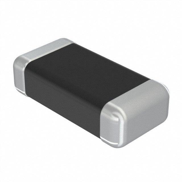
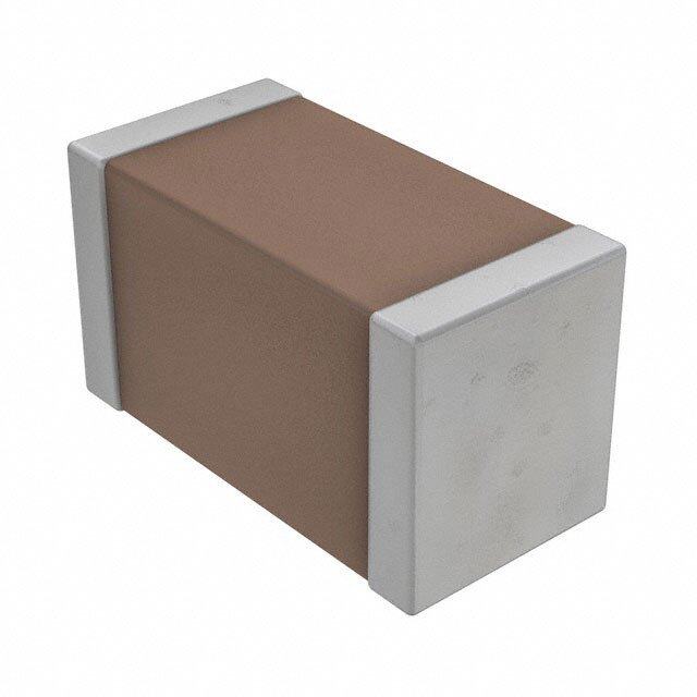
ICGOO电子元器件商城为您提供250R05L0R2AV4T由Johanson Dielectrics Inc.设计生产,在icgoo商城现货销售,并且可以通过原厂、代理商等渠道进行代购。 250R05L0R2AV4T价格参考¥0.08-¥0.89。Johanson Dielectrics Inc.250R05L0R2AV4T封装/规格:陶瓷电容器, 0.2pF ±0.05pF 25V 陶瓷电容器 C0G,NP0 0201(0603 公制)。您可以下载250R05L0R2AV4T参考资料、Datasheet数据手册功能说明书,资料中有250R05L0R2AV4T 详细功能的应用电路图电压和使用方法及教程。
250R05L0R2AV4T 是由 Johanson Technology Inc. 生产的一款多层陶瓷电容器(MLCC),主要用于需要高稳定性和高频性能的电子电路中。

该电容器的电容值为0.2pF,额定电压为50V,适用于高频和射频(RF)电路中的耦合、旁路和滤波应用。其高精度和低损耗特性使其特别适合用于无线通信设备、射频模块、功率放大器、滤波器和天线调谐电路等场景。

此外,该型号符合RoHS标准,具备良好的温度稳定性和可靠性,适用于工业级和通信级设备。在高频率工作环境下,其低ESR(等效串联电阻)和低ESL(等效串联电感)特性有助于减少信号损耗,提高电路性能。

总结来说,250R05L0R2AV4T 主要应用于射频通信系统、无线模块、测试仪器及其他对高频性能有高要求的电子设备中。
| 参数 | 数值 |
| 产品目录 | |
| 描述 | CAP CER 0.2PF 25V NP0 0201 |
| 产品分类 | |
| 品牌 | Johanson Technology Inc |
| 数据手册 | |
| 产品图片 |
|
| 产品型号 | 250R05L0R2AV4T |
| rohs | 无铅 / 符合限制有害物质指令(RoHS)规范要求 |
| 产品系列 | L |
| 产品培训模块 | http://www.digikey.cn/PTM/IndividualPTM.page?site=cn&lang=zhs&ptm=24831 |
| 产品目录绘图 |
|
| 产品目录页面 | |
| 其它名称 | 712-1173-6 |
| 包装 | Digi-Reel® |
| 厚度(最大值) | 0.013"(0.33mm) |
| 大小/尺寸 | 0.024" 长 x 0.012" 宽(0.60mm x 0.30mm) |
| 安装类型 | 表面贴装,MLCC |
| 容差 | ±0.05pF |
| 封装/外壳 | 0201(0603 公制) |
| 工作温度 | -55°C ~ 125°C |
| 应用 | RF,微波,高频 |
| 引线形式 | - |
| 引线间距 | - |
| 标准包装 | 1 |
| 温度系数 | C0G,NP0 |
| 特性 | 高 Q 值,低损耗 |
| 特色产品 | http://www.digikey.com/cn/zh/ph/Johanson/High-Q.html |
| 电压-额定 | 25V |
| 电容 | 0.20pF |
| 等级 | - |
| 高度-安装(最大值) | - |
.jpg)


- 商务部:美国ITC正式对集成电路等产品启动337调查
- 曝三星4nm工艺存在良率问题 高通将骁龙8 Gen1或转产台积电
- 太阳诱电将投资9.5亿元在常州建新厂生产MLCC 预计2023年完工
- 英特尔发布欧洲新工厂建设计划 深化IDM 2.0 战略
- 台积电先进制程称霸业界 有大客户加持明年业绩稳了
- 达到5530亿美元!SIA预计今年全球半导体销售额将创下新高
- 英特尔拟将自动驾驶子公司Mobileye上市 估值或超500亿美元
- 三星加码芯片和SET,合并消费电子和移动部门,撤换高东真等 CEO
- 三星电子宣布重大人事变动 还合并消费电子和移动部门
- 海关总署:前11个月进口集成电路产品价值2.52万亿元 增长14.8%

PDF Datasheet 数据手册内容提取
M -L H -Q C ULTI AYER IGH APACITORS These lines of multilayer capacitors have been developed for High-Q and microwave applications. • The S-Series (R07S, R14S, R15S) capacitors give an ultra- high Q performance, and exhibit NP0 temperature characteris- tics. • The L-Series (R05L) capacitors give mid-high Q performance, and exhibit NP0 temperature characteristics. • The E-Series (S42E, S48E, S58E) capacitors give excellent high-Q performance from HF to Microwave frequencies. Typical uses are high voltage, high current applications. They are offered in chip (Ni barrier or Non-Magnetic Pt.-Ag) or in Non-Magnetic leaded form. • RoHS compliance is standard for all unleaded parts (see termination options box). • Automotive versions (AEC-Q200) of R05L, R07S, R14S, R15S, and S42E series are available on request HOW TO ORDER 252 S48 E 470 K V 4 E -AEC WVDC2 CASE SIZE CAPACITANCE (pF) TOLERANCE TERMINATION PACKAGING QUALIFICATION 250 = 25 V R05 (0201) 1st two digits are < 10pF Nickel Barrier S = Bulk AEC-Q200 500 = 50V R07 (0402) significant; third digit A = ± 0.05 pF V = Ni/Sn (Green) W = Waffle Pack qualification 3 201 = 200 V R14 (0603) denotes number of B = ± 0.10 pF T = Ni/SnPb 0201 - 0603 (optional) 251 = 250 V R15 (0805) zeros, R = decimal. C = ± 0.25 pF G = Ni/Au (Green) Y = Paper 5” Reel 511005122 === 511005000 00V VV SSS445288 (((123158123158))) 110001 == 1100 0p pFF ≥ D 1 0=p ±F 0.50 pF NUC o==n CC-Muu//aSSgnn1 P (Gbreen) TRHJ1 o1= r =i= zP o PPanatpaappelleyre rOr7 5”1ri” e3R nR”et eeRedele Ele l-el c trodes 235622 == 23560000 VV DIELECTRIC FG == ±±12 %% Leaded (All Non- NVe1r ti=c aPllya pOerier n5te” dR Eeleecl t-ro des 722 = 7200 V S = Ultra High Q NPO J = ±5% Mag)1 L1 = Paper 7” Reel - L = High Q NPO K = ± 10% 1 = Microstrip Horizontally Oriented Electrodes E = Ultra High Q NPO, 2 = Axial Ribbon V1 = Paper 7” Reel - Part Number written: High Voltage, High For tolerance 3 = Axial Wire Vertically Oriented Electrodes Power availability, see 4 = Radial Ribbon 0805 - 3838 252S48E470KV4E G = Fully Oriented, chart. 5 = Radial Wire Z = Embossed 5” Reel E = Embossed 7” Reel Ultra High-Q NPO U1 = Embossed 13” Reel M1 = Embossed 5” Reel - Horizontally Oriented Electrodes Q1 = Embossed 5” Reel - MARKING Vertically Oriented Electrodes 3 = Cap Code G1 = Embossed 7” Reel - & Tolerance HPo1r i=zo Enmtalblyo Osrsieendte 7d ”E lReceterol d-e s 4 = No Marking Vertically Oriented Electrodes 6 = EIA Code Tape specifications (Marking option is only available conform to EIA RS481 on 0805 and larger case sizes) 1 - Not available for all MLCC - Call factory for info. 2 - WVDC - Working Voltage DC. 3 -Qualification required for automotive application, Not available for all series - Call factory for info. www.johansontechnology.com 7
LOW ESR / HIGH-Q CAPACITOR SELECTION CHART RF Power Applications EIA Size 0201 (R05) 0402 0603 0805 0805 1111 2525 3838 Cap. Value NPO NPO (R07S) (R14S) (R15S) (R15L) (S42E) (S48E) (S58E) (R05L) (R05G) Capacitance pF Code 0.1 0R1 0.2 0R2 25/50 V 25 V 50/250 V 250 V 500V 1500V 0.3 0R3 25/50 V 25 V 50/250 V 250 V 250 V 500V 1500V 0.4 0R4 25/50 V 25 V 50/250 V 250 V 250 V 500V 1500V 0.5 0R5 25/50 V 25 V 50/250 V 250 V 250 V 500V 1500V 3600V 0.6 0R6 25/50 V 25 V 50/250 V 250 V 250 V 500V 1500V 3600V 3600V 7200V 0.7 0R7 25/50 V 25 V 50/250 V 250 V 250 V 500V 1500V 3600V 3600V 7200V 0.8 0R8 25/50 V 25 V 50/250 V 250 V 250 V 500V 1500V 3600V 3600V 7200V 0.9 0R9 25/50 V 25 V 50/250 V 250 V 250 V 500V 1500V 3600V 3600V 7200V 1.0 1R0 25/50 V 25 V 50/250 V 250 V 250 V 500V 1500V 3600V 3600V 7200V 1.1 1R1 25/50 V 25 V 50/250 V 250 V 250 V 500V 1500V 3600V 3600V 7200V 1.2 1R2 A 25/50 V 25 V 50/250 V 250 V 250 V 500V 1500V 3600V 3600V 7200V 1.3 1R3 25/50 V 25 V 50/250 V 250 V 250 V 500V 1500V 3600V 3600V 7200V 1.4 1R4 B 25/50 V 25 V 50/250 V 250 V 250 V 500V 1500V 3600V 3600V 7200V 1.5 1R5 25/50 V 25 V 50/250 V 250 V 250 V 500V 1500V 3600V 3600V 7200V 1.6 1R6 25/50 V 25 V 50/250 V 250 V 250 V 500V 1500V 3600V 3600V 7200V C 1.7 1R7 25/50 V 25 V 50/250 V 250 V 250 V 500V 1500V 3600V 3600V 7200V 1.8 1R8 25/50 V 25 V 50/250 V 250 V 250 V 500V 1500V 3600V 3600V 7200V D 1.9 1R9 25/50 V 25 V 50/250 V 250 V 250 V 500V 1500V 3600V 3600V 7200V 2.0 2R0 25/50 V 25 V 50/250 V 250 V 250 V 500V 1500V 3600V 3600V 7200V 2.1 2R1 25/50 V 25 V 50/250 V 250 V 250 V 500V 1500V 3600V 3600V 7200V 2.2 2R2 25/50 V 25 V 50/250 V 250 V 250 V 500V 1500V 3600V 3600V 7200V 2.4 2R4 25/50 V 25 V 50/250 V 250 V 250 V 500V 1500V 3600V 3600V 7200V 2.7 2R7 25/50 V 25 V 50/250 V 250 V 250 V 500V 1500V 3600V 3600V 7200V 3.0 3R0 25/50 V 25 V 50/250 V 250 V 250 V 500V 1500V 3600V 3600V 7200V 3.3 3R3 25/50 V 25 V 50/250 V 250 V 250 V 500V 1500V 3600V 3600V 7200V 3.6 3R6 25/50 V 25 V 50/200 V 250 V 250 V 500V 1500V 3600V 3600V 7200V 3.9 3R9 25/50 V 25 V 50/200 V 250 V 250 V 500V 1500V 3600V 3600V 7200V 4.3 4R3 25/50 V 25 V 50/200 V 250 V 250 V 500V 1500V 3600V 3600V 7200V 4.7 4R7 25/50 V 25 V 50/200 V 250 V 250 V 500V 1500V 3600V 3600V 7200V 5.1 5R1 25/50 V 25 V 50/200 V 250 V 250 V 500V 1500V 3600V 3600V 7200V A** 5.6 5R6 25/50 V 25 V 50/200 V 250 V 250 V 500V 1500V 3600V 3600V 7200V 6.2 6R2 B 25/50 V 25 V 50/200 V 250 V 250 V 500V 1500V 3600V 3600V 7200V 6.8 6R8 25/50 V 25 V 50/200 V 250 V 250 V 500V 1500V 3600V 3600V 7200V C 7.5 7R5 25/50 V 25 V 50/200 V 250 V 250 V 500V 1500V 3600V 3600V 7200V 8.2 8R2 D 25/50 V 25 V 50/200 V 250 V 250 V 500V 1500V 3600V 3600V 7200V 9.1 9R1 25/50 V 25 V 50/200 V 250 V 250 V 500V 1500V 3600V 3600V 7200V 10 100 25/50 V 25 V 50/200 V 250 V 250 V 500V 1500V 3600V 3600V 7200V 11 110 25/50 V 25 V 50/200 V 250 V 250 V 500V 1500V 3600V 3600V 7200V 12 120 25/50 V 25 V 50/200 V 250 V 250 V 500V 1500V 3600V 3600V 7200V F 13 130 25/50 V 25 V 50/200 V 250 V 250 V 500V 1500V 3600V 3600V 7200V 15 150 25/50 V 25 V 50/200 V 250 V 250 V 500V 1500V 3600V 3600V 7200V G 16 160 25/50 V 25 V 50/200 V 250 V 250 V 500V 1500V 3600V 3600V 7200V 18 180 25/50 V 25 V 50/200 V 250 V 250 V 500V 1500V 3600V 3600V 7200V 20 200 J 25/50 V 50/200 V 250 V 250 V 500V 1500V 3600V 3600V 7200V 22 220 25/50 V 50/200 V 250 V 250 V 500V 1500V 3600V 3600V 7200V 24 240 K 25/50 V 50/200 V 250 V 250 V 500V 1500V 3600V 3600V 7200V 27 270 25/50 V 50/200 V 250 V 250 V 500V 1500V 3600V 3600V 7200V 30 300 25/50 V 50/200 V 250 V 250 V 500V 1500V 3600V 3600V 7200V 33 330 25/50 V 50/200 V 250 V 250 V 500V 1500V 3600V 3600V 7200V Consult factory for Non-Standard values. **A tolerance only available for R07S (0402) and R14S(0603) caps 8 www.johansontechnology.com
LOW ESR / HIGH-Q CAPACITOR SELECTION CHART RF Power Applications EIA Size 0201 (R05) 0402 0603 0805 0805 1111 2525 3838 Cap. Value NPO NP0 (R07S) (R14S) (R15S) (R15L) (S42E) (S48E) (S58E) (R05L) (R05G) Capacitance Toler- pF Code ance 36 360 25/50 V 250 V 250 V 500V 1500V 3600V 3600V 7200V 39 390 25/50 V 250 V 250 V 500V 1500V 3600V 3600V 7200V 43 430 25/50 V 250 V 250 V 500V 1500V 3600V 3600V 7200V 47 470 25/50 V 250 V 250 V 500V 1500V 3600V 3600V 7200V 51 510 25/50 V 250 V 250 V 500V 1500V 3600V 3600V 7200V 56 560 25/50 V 250 V 250 V 500V 1500V 3600V 3600V 7200V 62 620 25/50 V 250 V 250 V 500V 1500V 3600V 3600V 7200V 68 680 25/50 V 250 V 250 V 500V 1500V 3600V 3600V 7200V 75 750 25/50 V 250 V 250 V 500V 1500V 3600V 3600V 7200V 82 820 F 25/50 V 250 V 250 V 500V 1500V 3600V 3600V 7200V 91 910 25/50 V 250 V 250 V 500V 1500V 3600V 3600V 7200V 100 101 G 25/50 V 250 V 250 V 500V 1500V 3600V 3600V 7200V 110 111 250 V 300V 1500V 2500V 3600V 7200V 120 121 250 V 300V 1000V 2500V 3600V 7200V J 130 131 250 V 300V 1000V 2500V 3600V 7200V 150 151 250 V 300V 1000V 2500V 3600V 7200V K 160 161 250 V 300V 1000V 2500V 3600V 7200V 180 181 250 V 300V 1000V 2500V 3600V 7200V 200 201 250 V 300V 1000V 2500V 3600V 220 221 250 V 200V 1000V 2500V 3600V 240 241 500V 200V 600V 2500V 3600V 270 271 500V 200V 600V 2500V 3600V 300 301 500V 200V 600V 1500V 3600V 330 331 500V 200V 600V 1500V 3600V 360 361 500V 200V 600V 1500V 3600V 390 391 500V 200V 500V 1500V 3600V 430 431 500V 200V 500V 1500V 2500V 470 471 500V 200V 500V 1500V 2500V 510 511 100V 200V 500V 1000V 2500V 560 561 100V 200V 500V 1000V 2500V 620 621 100V 200V 500V 1000V 2500V 680 681 50V 200V 1000V 2500V 750 751 50V 200V 1000V 2500V 820 821 G 50V 200V 1000V 2500V 910 911 50V 200V 1000V 1000V 1000 102 J 50V 200V 1000V 1000V 1200 122 50V 1000V 1000V 1500 152 50V 500V 1000V K 1800 182 50V 500V 1000V 2200 222 50V 300V 1000V 2700 272 300V 500V 3300 332 500V 3900 392 500V 4700 472 500V 5100 512 500V 10000 103 Consult factory for Non-Standard values. www.johansontechnology.com 9
DIELECTRIC CHARACTERISTICS NPO TEMPERATURE COEFFICIENT: 0 ± 30ppm /°C, -55 to 150°C QUALITY FACTOR / DF: Q >1,000 @ 1KHz (C>1,000pF), Typical 10,000 (C<1,000 pF) INSULATION RESISTANCE: >100 GΩ @ 25°C,WVDC1; 125°C IR is 10% of 25°C rating DIELECTRIC STRENGTH: 500 V ≤ 2.5 X WVDC1 Min., 25°C, 50 mA max 1000 V ≤ 1.5 X WVDC1 Min., 25°C, 50 mA max > 1500 = 1 X WVDC1 Min., 25°C, 50 mA max TEST PARAMETERS:: 1MHz ±50kHz, 1.0±0.2 VRMS, 25°C AVAILABLE CAPACITANCE: Size 0201: 0.2 - 100 pF Size 1111: 0.2 - 1000 pF Size 0402: 0.2 - 33 pF Size 2525: 1.0 - 2700 pF Size 0603: 0.2 - 100 pF Size 3838: 1.0 - 5100 pF Size 0805: 0.3 - 220 pF MECHANICAL & ENVIRONMENTAL CHARACTERISTICS SPECIFICATION TEST PARAMETERS SOLDERABILITY: Solder coverage ≥ 90% of metalized areas Preheat chip to 120°-150°C for 60 sec., dip terminals in rosin flux No termination degradation then dip in Sn62 solder @ 240°±5°C for 5±1 sec RESISTANCE TO No mechanical damage Preheat device to 80°-100°C for 60 sec. SOLDERING HEAT: Capacitance change: ±2.5% or 0.25pF followed by 150°-180°C for 60 sec. Q>500 I.R. >10 G Ohms Dip in 260°±5°C solder for 10±1 sec. DWV2: 2.5 x WVDC1 Measure after 24±2 hour cooling period TERMINAL Termination should not pull off. Linear pull force3 exerted on axial leads soldered to each terminal. ADHESION: Ceramic should remain undamaged. PCB DEFLECTION: No mechanical damage. Glass epoxy PCB: 2 mm deflection Capacitance change: 5% or 0.5pF whichever is greater. LIFE TEST: MIL-STD-202, Method 108l Applied voltage: 200% of WVDC1 for capacitors rated at 500 volts DC or less. No mechanical damage 100% of WVDC1 for capacitors rated at 1250 volts DC or less. Capacitance change: ±3.0% or 0.3 pF Temperature: 125°±3°C Q>500 I.R. >1 G Ohms Test time: 1000+48-0 hours DWV2: 2.5 x WVDC1 THERMAL CYCLE: No mechanical damage. 5 cycles of: 30±3 minutes @ -55°+0/-3°C, Capacitance change: ±2.5% or 0.25pF 2-3 min. @ 25°C, 30±3 min. @ +125°+3/-0°C, Q>2000 I.R. >10 G Ohms 2-3 min. @ 25°C DWV2: 2.5 x WVDC1 Measure after 24±2 hour cooling period HUMIDITY, No mechanical damage. Relative humidity: 90-95% STEADY STATE: Capacitance change: ±5.0% or 0.50pF max. Temperature: 40°±2°C Q>300 I.R. ≥ 1 G-Ohm Test time: 500 +12/-0 Hours DWV2: 2.5 x WVDC1 Measure after 24±2 hour cooling period HUMIDITY, No mechanical damage. Applied voltage: 1.5 VDC, 50 mA max. LOW VOLTAGE: Capacitance change: ±5.0% or 0.50pF max. Relative humidity: 85±2% Temperature: 40°±2°C Q>300 I.R. = 1 G-Ohm min. Test time: 240 +12/-0 Hours DWV2: 2.5 x WVDC1 Measure after 24±2 hour cooling period VIBRATION: No mechanical damage. Capacitance change: ±2.5% or 0.25pF Cycle performed for 2 hours in each of three perpendicular directions Q>1000 I.R. ≥ 10 G-Ohm Frequency range 10Hz to 55 Hz to 10 Hz traversed DWV2: 2.5 x WVDC1 in 1 minute. Harmonic motion amplitude: 1.5mm 1 - WVDC - Working Voltage DC. 2 - DWV - Dielectric Withstanding Voltage. 3 - 0402 ≥ 2.0lbs, 0603 ≥ 4.0lbs (min). 4 - Whichever is less. AEC-Q200: Qualification required for automotive application - Not available for all series - Call factory for info. 10 wwwwww..jjoohhaannssoonntteecchhnnoollooggyy..ccoomm
MECHANICAL CHARACTERISTICS Size Units Length Width Thickness End Band EIA 0201 In .024 ±.001 .012 ±.001 .012 ±.001 .008 Max. Metric (0603) mm (0.60 ±0.03) (0.30 ±0.03) (0.30 ±0.03) (0.20 Max.) EIA 0402 In .040 ±.004 .020 ±.004 .020 ±.004 .010 ±.006 Metric (1005) mm (1.02 ±0.1) (0.51 ±0.1) (0.51 ±0.1) (0.25 ±.15) EIA 0603 In .062 ±.006 .032 ±.006 .030 +.005/-.003 .014 ±.006 Metric (1608) mm (1.57 ±0.15) (0.81 ±0.15) (0.76 +.13-.08) (0.35 ±.15) EIA 0805 In .080 ±.008 .050 ±.008 .040 ±.006 .020 ±.010 Metric (2012) mm (2.03 ±0.20) (1.27 ±0.20) (1.02 ±.15) (0.50 ±.25) HORIZONTAL AND VERTICLE ORIENTED CAPACITORS Horizontal Electrode Orientation Vertical Electrode Orientation APPLICATIONS & FEATURES Size: EIA 0201, 0805, 1111 Performance: SRF’s up to 20 GHz, Ultra High Q, Tight tolerance, Ultralow ESR Termination: Ni/Au, Ni/Sn, Ni/SnPb Applications: High Frequency Wireless Communications, Portable Wireless Products, Battery Powered Products RoHS Compliant BENIFITS OF USING ORIENTED CAPACITORS • Consistent Orientation - Improved repeatability of production circuits. • Consistent Orientation - More consistent filter performance. • Vertical Orientation - The elimination of parallel frequencies. • Vertical Orinetation - Lower inductance for a given capacitor. • Horizontal Orientation - Lower coupling between adjacent capacitors. wwwwww..jjoohhaannssoonntteecchhnnoollooggyy..ccoomm 11
E-SERIES TERMINATIONS AND LEADS CHIP DIMENSIONS Termination Size Units L Tol W Tol T E / B Tol For all E-Series Models: S42E In 0.110 +.020 -.010 0.110 +/- .015 0.102 Max. 0.015 Typ. +/- 0.008 OPERATING TEMP. : -55 to +125°C mm 2.79 +0.51 -0.25 2.79 +/- 0.38 2.59 Max. 0.38 Typ. +/- 0.20 INSULATION RESISTANCE: >10G Ω @ 25°C V,T S48E In 0.230 +.025 -.010 0.250 +/- .015 0.150 Max. 0.025 Typ. TEMPERATURE COEFFICIENT: 0 ± 30ppm /°C, -55 to U,C mm 5.84 +0.63 -0.25 6.35 +/- 0.38 3.81 Max. 0.63 Typ. 125°C S58E In 0.380 +.015 -.010 0.380 +/- .010 0.170 Max. 0.025 Typ. DISSIPATION FACTOR (TYP.): < 0.05% @ 1 MHz mm 9.65 +0.38 -0.25 9.65 +/- 0.25 4.32 Max. 0.63 Typ. Drawings not to scale Unleaded Termination Codes “V” (Ni/Sn), Microstrip Ribbon Leads (Non-Magnetic), Axial Ribbon Leads (Non-Magnetic), Termi- “T” (Ni/SnPb), “U” (Cu/Sn non-mag), “C” Termination Code “1” nation Code “2” (Cu/SnPb non-mag) e e W L E/B X X T LL LL LL LL Axial Wire Leads (Non-Magnetic), Radial Ribbon Leads (Non-Magnetic), Ter- Radial Wire Leads (Non-Magnetic), Termination Code “3” mination Code “4” Termination Code “5” e e LL LL X T LL LL W W LL LL T XX X W LL e e Lead Size LL(min) X Tol e e-Tol Lead Size LL(min) X Tol e e-Tol 0.25 0.093 +/-0.005 0.004 +/- 0.002 0.352 0.093 +/-0.005 0.004 +/- 0.002 S42E S42E 6.40 2.36 +/- 0.13 0.102 +/- 0.051 8.90 2.36 +/- 0.13 0.102 +/- 0.051 0.394 0.217 +/- 0.02 0.009 - 0.0019/+ 0.0031 0.501 0.217 +/- 0.02 0.009 - 0.0019/+ 0.0031 1 S48E 4 S48E 10.0 5.5 +/- 0.50 0.220 - 0.050/+ 0.080 12.70 5.50 +/- 0.50 0.220 - 0.050/+ 0.080 0.748 0.35 +/- 0.02 0.010 - 0.0019/+ 0.0039 0.886 0.35 +/- 0.02 0.010 - 0.0019/+ 0.0039 S58E S58E 19.00 8.90 +/- 0.50 0.250 - 0.050/+ 0.100 22.50 8.90 +/- 0.50 0.25 - 0.050/+ 0.100 0.25 0.093 +/-0.005 0.004 +/- 0.002 0.25 S42E S42E 6.40 2.36 +/- 0.13 0.102 +/- 0.051 6.40 0.394 0.217 +/- 0.02 0.009 - 0.0019/+ 0.0031 0.394 2 S48E 5 S48E 0.020in (0.511) diameter wire 10.00 5.50 +/- 0.50 0.220 - 0.050/+ 0.080 10.00 0.748 0.35 +/- 0.02 0.010 - 0.0019/+ 0.0039 0.748 S58E S58E 19.00 8.90 +/- 0.50 0.25 - 0.050/+ 0.100 19.00 0.25 S42E 6.40 0.394 3 S48E 0.020in (0.511) diameter wire 10.00 0.748 S58E 19.00 12 www.johansontechnology.com
RF CHARACTERISTICS - 0201 R05L SERIES More data at: https://jtisoft.johansontechnology.com ResonantFrequency : 0201/R05L 0201 R05L Resonant frequency 0201 R05L Equivalent Series Resistance (ESR) 100 300 Typical values of SRF with: Series mounting Hz) SRF H14o rmiziol-nthtaicl ko rFiRe4n t asutibosntrate 250 G ncy ( Ω)200 3.0 pF e m nt frequ 10 ESR (110500 1303 ppFF a 56 pF n o es 50 100 pF R Typical values 0 1 0 500 1000 1500 2000 1 10 100 Freq (MHz) Capacitance value (pF) The Series Resonant Frequency is highly dependent on the substrate, pad dimensions, and measurement method. The above chart is for reference only. 0201 R05L Q factor 0201 R05L Max Current 10000 3 Estimated maximum current based on Ambient temperature = 65 °C ms)2.5 Tsuhbesrtmraatle r e =s i3st0a0n°cCe/ Wof DUT on 1000 3.0 pF nt (A r 2 IDnufitnyi tcey chleea=t1s0in0k% 3 pF Q factor 100 1303 ppFF mum curre1.51 1303 ppFF xi 56 pF 10 56 pF Ma0.5 100 pF 100 pF 0 1 0 500 1000 1500 2000 0 500 1000 1500 2000 Freq (MHz) Freq (MHz) RF CHARACTERISTICS - 0402 R07S SERIES More data at: https://jtisoft.johansontechnology.com 0402 R07S Series Resonant frequency 0402 R07S Equivalent Series Resistance (ESR) 250 Typical values of SRF with: Series mounting Hz) H16o rmiziol-nthtaicl koRrioengetartsi o4n003substrate 200 G cy (10 Ω)150 2.2 pF nt frequen ESR (m100 511.056 pp pFFF a n 50 eso SRF 33 pF R Typical values 0 0 500 1000 1500 2000 1 Freq (MHz) 0.1 1 10 Capacitance value (pF) The Series Resonant Frequency is highly dependent on the substrate, pad dimensions, and measurement method. The above chart is for reference only. www.johansontechnology.com 13
RF CHARACTERISTICS 0402 R07S SERIES More data at: https://jtisoft.johansontechnology.com 0402 R07S Q factor 0402 R07S Max Current 10000 5 Estimated maximum current based on 4.5 Ambient temperature = 65 °C ms) 4 ITnhfeinrimtea lh reeastissitnaknce of DUT on substrate = 120°C/W 1000 A r3.5 Duty cycle=100% Q factor 100 251..026 p ppFFF ximum current (12..5523 3115350.6 ppp pFFFF 10 15 pF Ma 1 2.2 pF 33 pF 0.5 Typical values 0 1 0 500 1000 1500 2000 0 500 1000 1500 2000 Freq (MHz) Freq (MHz) RF CHARACTERISTICS 0603 R14S SERIES More data at: https://jtisoft.johansontechnology.com 0603 R14S Series Resonant frequency 0603 R14S Equivalent Series Resistance (ESR) 100 Typical values of SRF with: 280 Series mounting Hz) H16o rmiziol-nthtaicl koRrioengetarsti o4n003substrate 240 G y ( 200 2.0 pF enc mΩ)160 4.7 pF ant frequ 10 ESR (12800 1309 ppFF n 75 pF Reso SRF 40 Typical values 100 pF 0 0 500 1000 1500 2000 1 Freq (MHz) 0.1 1 10 100 Capacitance value (pF) The Series Resonant Frequency is highly dependent on the substrate, pad dimensions, and measurement method. The above chart is for reference only. 0603 R14S Q factor 0603 R14S Max Current 10000 8 Estimated maximum current based on Ambient temperature = 65 °C 7 Thermal resistance of DUT on substrate = 60°C/W 1000 2.0 pF ms)6 IDnufitnyi tcey chleea=t1s0in0k% 100 pF 4.7 pF A r Q factor 100 1309 ppFF m current (45 7359 ppFF u3 10 pF m 10 75 pF axi2 4.7 pF M 100 pF 1 2.0 pF Typical values 1 0 0 500 1000 1500 2000 0 500 1000 1500 2000 Freq (MHz) Freq (MHz) 14 www.johansontechnology.com
RF CHARACTERISITCS - 0805 R15S SERIES More data at: https://jtisoft.johansontechnology.com 0805 R15S Series Resonant frequency 0805 R15S Equivalent Series Resistance (ESR) 300 Typical values with: Series mounting 250 0.3 pF Hz)10 H16o rmiziol-nthtaicl ko rRioengetartsi o4n003C substrate 2.0 pF nt frequency (G ESR (mΩ)112050000 4137.0957 ppp pFFFF a son SRF 50 100 pF e R Typical values 220 pF 0 0 500 1000 1500 2000 1 1 10 100 Freq (MHz) Capacitance value (pF) The Series Resonant Frequency is highly dependent on the substrate, pad dimensions, and measurement method. The above chart is for reference only. 0805 R15S Q factor Effective capacitance value: 0805/R15S 10000 0.3 pF 400 Typicalvalues on a 16 mil RO4003C 1000 2.0 pF pF)350 4.7 pF ue (300 Q factor 10100 137095 pppFFF Capacitance Val122505000 CCC(((111 MMMHHHzzz))) === 21520600 p ppFFF 100 pF ve 100 Typical values 220 pF Effecti 50 1 0 0 500 1000 1500 2000 0 200 400 600 800 1000 1200 1400 1600 1800 2000 Freq (MHz) Freq (MHz) 0805 R15S Max Current vs. Cap. Value 0805 R15S Max Current vs. Frequency 100 EstimAamtebdi emnta xteimmupmer cauturrreen =t 6b5a s°eCd on 10 EstimAamtebdi emnta xteimmupmer cauturrreen =t 6b5a s°eCd on ITnhfeinrimtea lh reeastissitnaknce of DUT on substrate = 40°C/W 300 MHz ms) ITnhfeinrimtea lh reeastissitnaknce of DUT on substrate = 40°C/W 220 pF A rms) 10 Duty cycle=100% 128 MHz nt (A r 8 Duty cycle=100% 17050 p pFF nt ( 100 MHz urre 6 39 pF e c mum curr 1 6247 MMHHzz Maximum 24 1420..70 p ppFFF axi 0.1 13 MHz 0.3 pF M 7 MHz 0 0 500 1000 1500 2000 0.01 Freq (MHz) 0.1 1 10 100 Capacitance value (pF) www.johansontechnology.com 15
RF CHARACTERISTICS - 1111 S24E SERIES More data at: https://jtisoft.johansontechnology.com 1111 S42E Series Resonant frequency 1111 S42E Equivalent Series Resistance (ESR) 300 Typical values with: Hz) 10 SH6e0or rmiiezisol -nmthtoaiclu kon rRtiioennggetartsi o4n350B substrate 250 G y ( 200 1.2 pF nc Ω) 4.7 pF e m nt frequ 1 SRF ESR (110500 1303 ppFF a on 100 pF s 50 e R 300 pF Typical values 0 0.1 0 500 1000 1500 2000 1 10 100 1000 Freq (MHz) Capacitance value (pF) The Series Resonant Frequency is highly dependent on the substrate, pad dimensions, and measurement method. The above chart is for reference only. 1111 S42E Q factor Effective capacitance value: 1111/S42E 10000 S42E 400 Typical values ona 60-mil thick F)350 Rogers 4350B substrate 1000 0.2 pF ue (p300 1.2 pF al v Q factor 100 41.07 p pFF acitance 220500 CC((11 MMHHzz)) == 310000p pFF ap150 C(1 MHz) = 10 pF 33 pF e c 10 100 pF ectiv100 Eff 50 300 pF Typical values 0 1 0 500 1000 1500 2000 0 500 1000 1500 2000 Freq (MHz) Freq (MHz) 1111 S42E Max Current vs. Capacitance Value 1111 S42E Max Current vs. Frequency 1000 20 Estimated maximum current based on Estimated maximum current based on Ambient temperature = 65 °C 18 Ambient temperature = 65 °C ent (A rms) 10100 IDTnhufeitnyrim tceya clh lreeea=st1iss0itn0ak%nce of DUT on substrate = 20°C/W 200 MHz urrent (A rms)11110246 IDTnhufeitnyrim tceya clh lreeea=st1iss0itn0ak%nce of DUT on substrate = 20°C/W 31300300 p ppFFF urr 100 MHz m C 8 10 pF ximum C 1 40 MHz Maximu 46 41..72 ppFF Ma 0.1 15 MHz 2 0.2 pF 0 7 MHz 0 500 1000 1500 2000 0.01 Freq (MHz) 0.1 1 10 100 1000 Capacitance value (pF) 16 www.johansontechnology.com
RF CHARACTERISTICS - 2525 S48E SERIES More data at: https://jtisoft.johansontechnology.com 2525 S48E Series Resonant Frequency 2525 S48E Equivalent Series Resistance (ESR) 10 140 Typical values of SRF when measured on a 8720C VNA 120 using a shunt-through fixture 100 Hz) Ω) 80 10 pF G m ncy ( 1 ESR ( 60 2323 ppFF e qu 40 130 pF e Fr 20 470 pF SRF Typical values 0 0 50 100 150 200 250 300 0.1 Freq (MHz) 1 10 100 1000 Capacitance (pF) The Series Resonant Frequency is highly dependent on the substrate, pad dimensions, and measurement method. The above chart is for reference only. 2525 S48E Q factor 2525 S48E Max Current vs. Frequency 10000 20 Estimated maximum current based on 18 Ambient temperature = 65 °C Thermal resistance of DUT on substrate = 15°C/W 16 Infinite heatsink 1000 14 Duty cycle=100% 10 pF ms)12 470 pF Q factor 100 2323 ppFF Imax (A r1068 1323320 pp pFFF 10 130 pF 4 10 pF 470 pF 2 Typical values 0 1 0 50 100 150 200 250 300 0 50 100 150 200 250 300 Freq (MHz) Freq (MHz) wwwwww..jjoohhaannssoonntteecchhnnoollooggyy..ccoomm 17
RF CHARACTERISTICS - 3838 S58E SERIES 3838 S58E Series Resonant frequency 3838 S58E Equivalent Series Resistance (ESR) 10 180 Typical values of SRF when measured on a 8720C VNA 160 using a shunt-through fixture 140 Hz) 1 120 ency (G R (mΩ)10800 1407 ppFF u S q E Fre 0.1 60 180 pF 40 1000 pF 20 SRF Typical values 0.01 0 1 10 100 1000 0 50 100 150 200 250 300 Capacitance (pF) Freq (MHz) The Series Resonant Frequency is highly dependent on the substrate, pad dimensions, and measurement method. The above chart is for reference only. 3838 S58E Q factor 3838 S58E Max Current vs. Frequency 10000 Estimated maximum current based on Ambient temperature = 65 °C Thermal resistance of DUT on substrate = 12°C/W 1000 ms)20 IDnufitnyi tcey chleea=t1s0in0k% A r or 10 pF ent (15 10 pF Q fact 100 47 pF m curr10 47 pF 180 pF mu 180 pF xi 10 1000 pF Ma 5 1000 pF Typical values 0 1 0 50 100 150 200 250 300 0 50 100 150 200 250 300 Freq (MHz) Freq (MHz) 18 www.johansontechnology.com
Mouser Electronics Authorized Distributor Click to View Pricing, Inventory, Delivery & Lifecycle Information: J ohanson: 250R05L1R8BV4T 500R07S100FV4T 500R07S2R0BV4T 251R14S2R2BV4T 251R14S0R6BV4T 500R07S0R4AV4T 500R07S0R3BV4T 500R07S150FV4T 251R14S1R8BV4T 250R05L1R0BV4T 251R14S1R2BV4T 251R14S2R0BV4T 251R14S1R0BV4T 250R05L1R5BV4T 500R07S1R2BV4T 500R07S3R0BV4T 500R07S4R7BV4T 251R14S3R0BV4T 500R07S100GV4T 500R07S270JV4T 500R07S0R9BV4T 251R14S3R9BV4T 500R07S2R2BV4T 250R05L3R6CV4T 500R07S5R6BV4T 251R14S0R5BV4T 500R07S2R7BV4T 500R07S1R3BV4T 500R07S100JV4T 500R07S2R4BV4T 251R14S120GV4T 500R07S5R6CV4T 500R07S1R2AV4T 250R05L1R2BV4T 500R07S1R5BV4T 500R07S6R8CV4T 251R14S330GV4T 500R07S0R7BV4T 500R07S0R4BV4T 500R07S200GV4T 500R07S1R0BV4T 500R07S3R9BV4T 500R07S3R3BV4T 500R07S1R8BV4T 251R14S0R8BV4T 500R07S0R8BV4T 251R14S1R5BV4T 251R14S150JV4T 251R14S100GV4T 251R14S430JV4T 251R14S470JV4T 251R14S270JV4T 251R14S6R8CV4T 500R07S8R2CV4T 500R07S0R5BV4T 500R07S1R5AV4T 251R14S3R3BV4T 500R07S0R5AV4T 251R14S180JV4T 250R05L5R1DV4T 500R07S1R7BV4T 301S42E111JV4E 251R15S2R0DV4E 251R15S820KV4E 251R14S1R3CV4T 251R14S470KV4T 250R05L180JV4T 251R15S131JV4E 500S42E751JV4E 201S42E241FV4E 251R15S120GV4E 250R05L5R6DV4T 250R05L6R2CV4T 251R14S510GV4T 250R05L120JV4T 251R15S221GV4E 500R07S7R5BV4T 251R14S3R3DV4T 201R07S2R1DV4T 251R15S101FV4E 251R14S160KV4T 500R07S8R2BV4T 201R07S2R1AV4T 250R05L4R3CV4T 251R15S820FV4E 250R05L160KV4T 500R07S1R1AV4T 251R14S470FV4T 201S42E471KV4E 251R15S161JV4E 251R15S3R0BV4E 250R05L1R9BV4T 251R14S1R9AV4T 250R05L8R2BV4T 251R14S240JV4T 251R14S680JV4T 201S42E361FV4E 500R07S2R1CV4T 500R07S2R0CV4T 301S42E161JV4E