ICGOO在线商城 > 电源 - 外部/内部(外接) > 直流转换器 > 2320018
 Datasheet下载
- 型号: 2320018
- 制造商: Phoenix Contact
- 库位|库存: xxxx|xxxx
- 要求:
| 数量阶梯 | 香港交货 | 国内含税 |
| +xxxx | $xxxx | ¥xxxx |
查看当月历史价格
查看今年历史价格
2320018产品简介:
ICGOO电子元器件商城为您提供2320018由Phoenix Contact设计生产,在icgoo商城现货销售,并且可以通过原厂、代理商等渠道进行代购。 2320018价格参考。Phoenix Contact2320018封装/规格:直流转换器, 。您可以下载2320018参考资料、Datasheet数据手册功能说明书,资料中有2320018 详细功能的应用电路图电压和使用方法及教程。
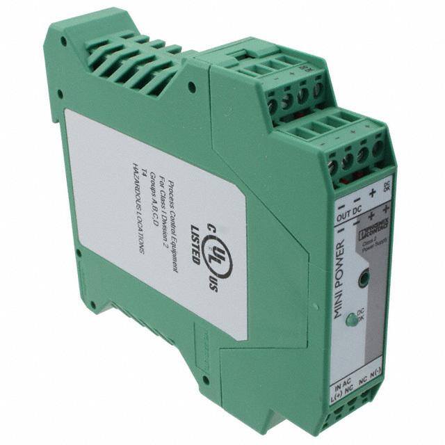
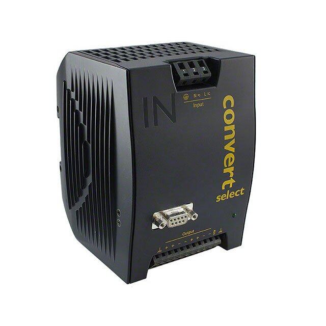
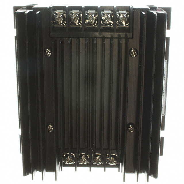
Phoenix Contact的直流转换器型号2320018主要应用于工业自动化和电气控制系统中,适用于需要稳定直流电压转换的场合。该转换器可将输入的直流电压转换为所需的输出电压,以供不同的直流设备使用,广泛应用于机械制造、生产线控制、楼宇自动化、能源管理系统以及交通工程等领域。

其典型应用场景包括PLC控制系统中的电源适配、传感器与执行器的供电、工业计算机或人机界面(HMI)设备的电源转换等。由于其具备良好的抗干扰能力和较高的转换效率,因此在复杂电磁环境和对电源质量要求较高的场合中表现优异。

此外,该产品还适用于分布式控制系统(DCS)和现场总线系统中,用于为远程I/O模块提供可靠的直流电源支持。其紧凑的设计也使其适用于空间受限的控制柜内安装,便于系统集成和维护。
| 参数 | 数值 |
| 产品目录 | |
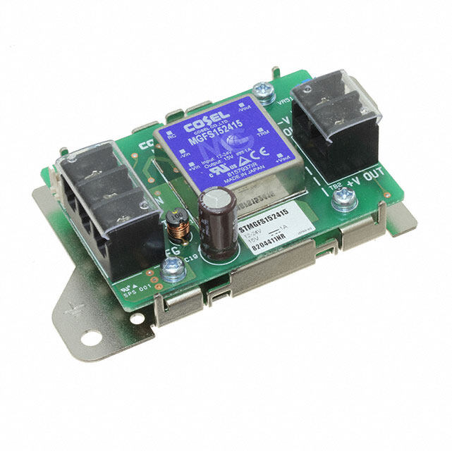
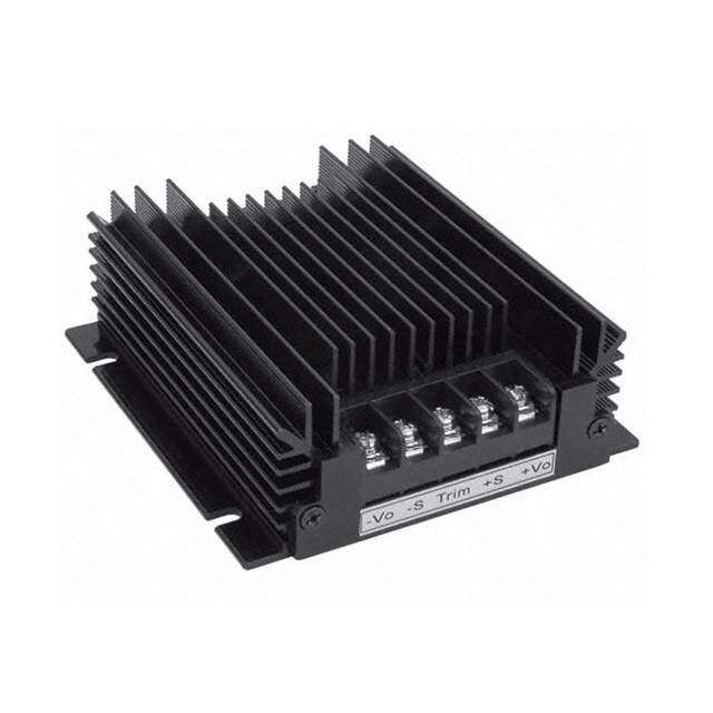
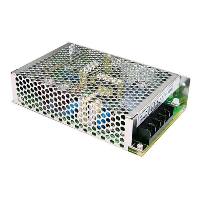
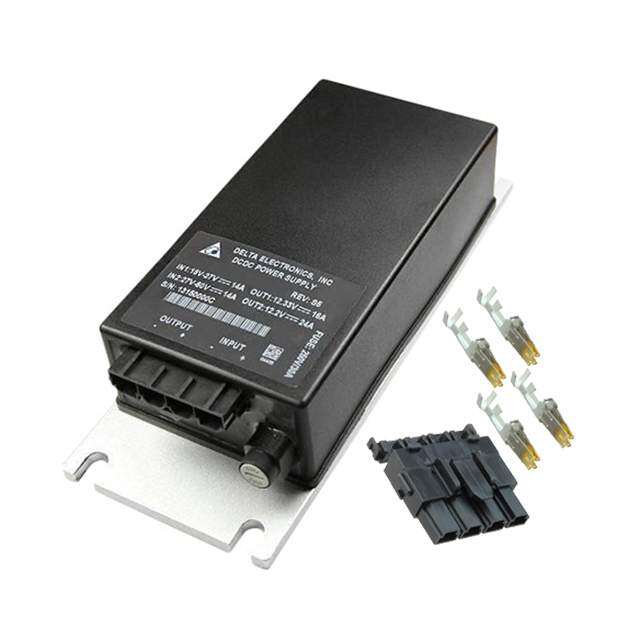
| 描述 | CONVERTER DC-DC 12-24/5-15VDC 2A隔离式DC/DC转换器 MINI-PS- 12- 24DC/ 5-15DC/2 |
| 产品分类 | DC DC ConvertersDC/DC转换器 |
| 品牌 | Phoenix Contact |
| 产品手册 | http://www.phoenixcontact.com/gb/products/2320021/pdf |
| 产品图片 |
|
| rohs | 符合RoHS无铅 / 符合限制有害物质指令(RoHS)规范要求 |
| 产品系列 | 隔离式DC/DC转换器,Phoenix Contact 2320018MINI |
| 数据手册 | http://select.phoenixcontact.com/phoenix/dwld/db_en_mini_ps_12_24dc_5_15dc_2_104346_en_01.pdf;jsessionid=CA42D5BA18D0F3023D7C7DFB7410D5D1.select-lin-dmz-app02-download?cp=y&asid2=147245952053230 |
| 产品型号 | 2320018 |
| 不同电流时的输出(最大值)-1 | 12 VDC @ 2A |
| 不同电流时的输出(最大值)-2 | - |
| 不同电流时的输出(最大值)-3 | - |
| 不同电流时的输出(最大值)-4 | - |
| 产品 | Isolated |
| 产品种类 | 隔离式DC/DC转换器 |
| 其它名称 | 2320018-ND |
| 功率(W) | 24W |
| 功率(W)-最大值 | 24W |
| 包装 | 散装 |
| 商标 | Phoenix Contact |
| 商标名 | MINI POWER |
| 大小/尺寸 | 4.21" 长 x 0.89" 宽 x 3.90" 高(107.0mm x 22.5mm x 99.0mm) |
| 安装类型 | DIN 轨道 |
| 安装风格 | DIN Rail |
| 宽度 | 0.89 in |
| 封装/外壳 | 模块 |
| 封装/箱体尺寸 | 107 mm x 22.5 mm x 99 mm |
| 尺寸 | 4.21 in x 0.89 in x 3.9 in |
| 工作温度 | -25°C ~ 70°C |
| 工作温度范围 | - 25 C to + 70 C |
| 工厂包装数量 | 1 |
| 效率 | 88% |
| 标准包装 | 1 |
| 电压-输入 | 12 ~ 24 V |
| 相关产品 | /product-detail/zh/0801681/277-7262-ND/348321/product-detail/zh/0801733/277-2293-ND/348323/product-detail/zh/0801762/277-7266-ND/348324/product-detail/zh/1201714/277-7263-ND/348391/product-detail/zh/1201730/277-2297-ND/348392/product-detail/zh/1201756/277-7267-ND/348393/product-detail/zh/1201798/277-7268-ND/348394/product-detail/zh/1201895/277-8224-ND/348399/product-detail/zh/0807012/277-2064-ND/2179626/product-detail/zh/0801704/277-5432-ND/2263803/product-detail/zh/1207640/277-5375-ND/2263804/product-detail/zh/1207666/277-5592-ND/2263805/product-detail/zh/1206421/277-5358-ND/2263806/product-detail/zh/1207653/277-2123-ND/2263939/product-detail/zh/0801759/277-5553-ND/2528606/product-detail/zh/1206434/277-5674-ND/2528607/product-detail/zh/0814681/277-5425-ND/2528608/product-detail/zh/1207679/1207679-ND/2528610/product-detail/zh/1207682/277-5614-ND/2528611/product-detail/zh/0806602/277-5578-ND/2528612/product-detail/zh/1206599/277-5504-ND/2528613/product-detail/zh/1206586/277-5675-ND/2528614/product-detail/zh/0801377/277-5452-ND/2528615/product-detail/zh/1204119/277-7401-ND/3596739/product-detail/zh/1208018/1208018-ND/3607564/product-detail/zh/1207695/1207695-ND/3607565/product-detail/zh/1206418/277-8227-ND/3607568/product-detail/zh/0801775/0801775-ND/3608161/product-detail/zh/1210006/1210006-ND/4471233/product-detail/zh/1210019/1210019-ND/4471234/product-detail/zh/1201701/1201701-ND/4471236/product-detail/zh/1204122/1204122-ND/4471237/product-detail/zh/5404669/5404669-ND/4473724 |
| 类型 | 隔离 |
| 系列 | MINI-PS |
| 认可 | cUL,EN,UL,VDE |
| 输入电压—公称值 | 12 V |
| 输入电压范围 | 10 V to 32 V |
| 输出 | 12V |
| 输出功率 | 24 W |
| 输出数 | 1 |
| 输出电压—通道1 | 12 V |
| 输出电流—通道1 | 2 A |
| 输出端数量 | 1 |
| 输出类型 | DC/DC Converter |
| 长度 | 4.21 in |
| 零件号别名 | MINI-PS-_12-_24DC/_5-15DC/2 MINIPS1224DC515DC2 |
| 高度 | 3.9 in |


- 商务部:美国ITC正式对集成电路等产品启动337调查
- 曝三星4nm工艺存在良率问题 高通将骁龙8 Gen1或转产台积电
- 太阳诱电将投资9.5亿元在常州建新厂生产MLCC 预计2023年完工
- 英特尔发布欧洲新工厂建设计划 深化IDM 2.0 战略
- 台积电先进制程称霸业界 有大客户加持明年业绩稳了
- 达到5530亿美元!SIA预计今年全球半导体销售额将创下新高
- 英特尔拟将自动驾驶子公司Mobileye上市 估值或超500亿美元
- 三星加码芯片和SET,合并消费电子和移动部门,撤换高东真等 CEO
- 三星电子宣布重大人事变动 还合并消费电子和移动部门
- 海关总署:前11个月进口集成电路产品价值2.52万亿元 增长14.8%

PDF Datasheet 数据手册内容提取
MINI-PS- 12- 24DC/ 5-15DC/2 Power supply unit INTERFACE Data sheet 104346_en_01 ' PHOENIX CONTACT 2011-09-21 1 Description Features The DC/DC converter converts the DC voltage of 12 V DC ... (cid:150) Reliable power supply unit even at high ambient 24 V DC to an adjustable, controlled and electrically isolated temperatures 5 V DC ... 15 V DC output voltage. (cid:150) Reliable starting of heavy loads using the U/I Due to electrical isolation, the DC voltage circuits are characteristic curve electrically isolated from each other in a safe way. The active (cid:150) Can be used worldwide in all industrial sectors due to a "DC-OK" switching output as well as an LED are available for wide-range input and an international approval package signaling. With a design width of only 22.5 mm, the housing is (cid:150) High operating safety due to long mains buffering under extremely slim. full load and high MTBF (> 500,000 h) DANGER OF EXPLOSION! Only remove equipment when it is disconnected and not in the potentially explosive area. DANGER Components with dangerously high voltage and high stored energy are located in the device! Never carry out work on live parts! Depending on the ambient temperature and the load, the housing can become very hot! Make sure you always use the latest documentation. It can be downloaded from the product at www.phoenixcontact.net/catalog.
MINI-PS- 12- 24DC/ 5-15DC/2 2 Table of contents 1 Description..................................................................................................................................1 Features.....................................................................................................................................................................1 2 Table of contents.........................................................................................................................2 3 Ordering data..............................................................................................................................3 4 Technical data.............................................................................................................................3 5 Structure......................................................................................................................................5 6 Block diagram.............................................................................................................................6 7 Safety notes................................................................................................................................6 8 Installation...................................................................................................................................7 9 Mounting position........................................................................................................................7 Assembly...................................................................................................................................................................8 Removing...................................................................................................................................................................8 10 Input............................................................................................................................................8 Protection of the primary side.....................................................................................................................................8 11 Output.........................................................................................................................................9 Protection of the secondary side................................................................................................................................9 12 Signaling.....................................................................................................................................9 Active signal output..................................................................................................................................................10 13 Function....................................................................................................................................10 Thermal behavior.....................................................................................................................................................10 Parallel operation.....................................................................................................................................................10 Redundant operation...............................................................................................................................................11 Increased performance............................................................................................................................................11 104346_en_01 PHOENIX CONTACT 2
MINI-PS- 12- 24DC/ 5-15DC/2 3 Ordering data Description Type Order No. Pcs. / Pkt. DC/DC converter, primary-switched, slim design, input: 12 - 24 V DC, MINI-PS- 12- 24DC/ 5-15DC/2 2320018 1 output: 5 - 15 V DC/2 A 4 Technical data Input data Nominal input voltage range 12 V DC ... 24 V DC DC input voltage range 10 V DC ... 32 V DC (> 10.5 V DC start) DC frequency range 0 Hz Current consumption Approx. 2.3 A (12 V DC) Approx. 1.1 A (24 V DC) Inrush current limitation < 10 A (typical) I2t 0.2 A2s Power failure bypass > 4 ms (12 V DC) > 18 ms (24 V DC) Typical response time < 0.5 s Input fuse, integrated 6.3 A (slow-blow, internal) Output data Nominal output voltage 12 V DC –1% Setting range of the output voltage 5 V DC ... 15 V DC Output current 2 A (-25 (cid:176)C ... 60 (cid:176)C) Efficiency > 88 % (at 24 V DC and nominal values) Residual ripple < 20 mV (20 MHz) PP Peak switching voltages < 10 mV (20 MHz) PP Connection in parallel Yes, for assembling redundant systems and increasing efficiency Connection in series Yes Protection against internal surge voltages Yes, < 25 V DC Resistance to reverse feed 30 V DC Power consumption Maximum power dissipation idling < 1 W Power loss nominal load max. < 4.2 W DC OK active Output description UOUT > 0.9 x UN: High signal Status display "DC OK" LED green / UOUT > 0.9 x UN: LED ON General data Insulation voltage input/output 1 kV (routine test) 1.5 kV (type test) Degree of protection IP20 Protection class III MTBF (IEC 61709) 500000 h Type of housing Polyamide PA, color: green Housing material Polyamide (PA) Dimensions W / H / D (state of delivery) 22.5 mm / 99 mm / 107 mm Weight 0.2 kg 104346_en_01 PHOENIX CONTACT 3
MINI-PS- 12- 24DC/ 5-15DC/2 Ambient conditions Ambient temperature (operation) -25 (cid:176)C ... 70 (cid:176)C (> +60(cid:176)C derating) Ambient temperature (storage/transport) -40 (cid:176)C ... 85 (cid:176)C Max. permissible relative humidity (operation) ≤ 95 % (At +25(cid:176)C, no condensation) Vibration (operation) < 15 Hz, amplitude –2.5 mm in acc. with IEC 60068-2-6 15 Hz ...150 Hz, 2.3 g Shock 30g in all directions in acc. with IEC 60068-2-27 Pollution degree in acc. with EN 50178 2 Climatic class 3K3 (in acc. with EN 60721) Approvals UL approvals UL/C-UL listed UL 508 UL/C-UL Recognized UL 60950 Current approvals can be found for the product in the download area. Conformance with EMC Directive 2004/108/EC Noise immunity according to EN 61000-6-2 Electrostatic discharge EN 61000-4-2 Housing > Level 3 Contact discharge 8 kV (Contact discharge) Discharge in air 8 kV (Air discharge) Comments Criterion B Electromagnetic HF field EN 61000-4-3 Housing Level 3 Frequency range 80 MHz ... 3 GHz Comments Criterion A Fast transients (burst) EN 61000-4-4 Input 4 kV (level 4 - asymmetrical: conductor to ground) Output 2 kV (level 3 - asymmetrical: conductor to ground) Signal 1 kV (Level 2 - asymmetrical cable to ground) Comments Criterion B Surge current loads (surge) EN 61000-4-5 Input 2 kV (Level 3) 1 kV (Level 3) Conducted interference EN 61000-4-6 Input/output Level 3 Frequency range 0.15 MHz ... 80 MHz (10 V) Voltage dips EN 61000-4-11 Input (> 10 ms) Comments Criterion B Emitted interference in acc. with EN 61000-6-3 Radio interference voltage in acc. with EN 55011 EN 55011 (EN 55022) Class B, area of application: Industry and residential Emitted radio interference in acc. with EN 55011 EN 55011 (EN 55022) Class B, area of application: Industry and residential 104346_en_01 PHOENIX CONTACT 4
MINI-PS- 12- 24DC/ 5-15DC/2 5 Structure 1 DC input 2 DC output 3 LED green: DC OK 5 4 Potentiometer: 5 V DC ... 15 V DC 5 Active switching output: DC OK 6 Universal snap-on foot for EN DIN rails 2 6 - WERO-UTD--C5-++15V2DO+ACK O P NI 43 MI 5V-D1C5 [mm2] AWG [Nm] DOCK solid stranded Torque Input 0.2-2.5 0.2-2.5 24-14 0.5-0.6 +INDNCC12N-C24V OSiugtnpault 00..22--22..55 00..22--22..55 2244--1144 00..55--00..66 1 - Input data Nominal input voltage range 12 V DC ... 24 V DC DC input voltage range 10 V DC ... 32 V DC (> 10.5 V DC start) DC frequency range 0 Hz Input fuse, integrated 6.3 A (slow-blow, internal) Connection method Pluggable screw connection Stripping length 7 mm Output data Nominal output voltage 12 V DC –1% Setting range of the output voltage 5 V DC ... 15 V DC Output current 2 A (-25 (cid:176)C ... 60 (cid:176)C) Connection method Pluggable screw connection Stripping length 7 mm 104346_en_01 PHOENIX CONTACT 5
MINI-PS- 12- 24DC/ 5-15DC/2 6 Block diagram NC NC DCOK 7 Safety notes DANGER OF EXPLOSION! Only remove equipment when it is disconnected and not in the potentially explosive area. DANGER Components with dangerously high voltage and high stored energy are located in the device! Never carry out work on live parts! Depending on the ambient temperature and the load, the housing can become very hot! CAUTION: Before startup please ensure: The mains connection has been carried out by a competent person and protection against electric shock is guaranteed! The device can be disconnected outside the power supply unit in accordance with the regulations as in EN 60950 (e.g. through primary side line protection)! All feed lines are sufficiently protected and dimensioned! All output lines are dimensioned according to the maximum output current of the device or separately protected! Sufficient convection must be guaranteed. ATTENTION: Danger if used improperly The power supply units are built-in devices. The device may only be installed and put into operation by qualified personnel. The corresponding national regulations must be observed. 104346_en_01 PHOENIX CONTACT 6
MINI-PS- 12- 24DC/ 5-15DC/2 8 Installation ATTENTION: Module can become damaged To ensure sufficient convection, we recommend the following minimum spacing be used between modules: 5 cm above and below The power supply unit can be snapped onto all DIN rails in acc. with EN 60715. - OUTD--C ++ DOCK + VDC DOCK +INDC NC NC - 9 Mounting position 22,5 113,5 107 0 3 159 129 MINIPOWERO--UTD--C++VDCDO+CK DOCK +INDNCCNC- Mounting position: Installation depth 107 mm (+ DIN rail) 104346_en_01 PHOENIX CONTACT 7
MINI-PS- 12- 24DC/ 5-15DC/2 Assembly A B Position the module with the DIN rail guide on the upper edge B 2 of the DIN rail, and snap it in with a downward motion. Removing Pull the snap lever open with the aid of a screwdriver and slide the module out at the lower edge of the DIN rail. B 1 10 Input ATTENTION: Module can become damaged If an internal fuse is triggered, there is a device malfunction. In this case, the device must be inspected in the factory. The 12 V DC ... 24 V DC connection is established using the "+" and "-" screw connections. Protection of the primary side The device must be installed in acc. with the regulations as in - OUTD--C ++ DOCK EANdd 6it0io9n5a0l. d Aenv iicnete prnroatle fcutsioen is is p nroovt irdeeqdu ifroerd d.evice protection. + VDC DOCK +INDC NC NC - 104346_en_01 PHOENIX CONTACT 8
MINI-PS- 12- 24DC/ 5-15DC/2 11 Output ATTENTION: Module can become damaged Make sure that all output lines are dimensioned according to the maximum output current or are separately protected. The cables on the secondary side must have sufficiently large cross sections in order to keep the voltage drops on the lines as low as possible. The connection is made via screw connection terminal blocks "+" and "-" of the DC output. The output voltage can be set on O-UTD--C ++ DOCK the potentiometer from 5 V DC ... 15 V DC. + Protection of the secondary side The device is electronically protected against short-circuit and idling. In the event of a malfunction, the output voltage is VDC DOCK limited to 25 V DC. Make sure that all output lines are dimensioned according to the maximum output current or are separately protected. The cable cross sections in the +INDC NC secondary circuit should be large enough to keep the voltage NC - drops on the cables as low as possible. 12 Signaling For function monitoring, there is the active DC OK switching output and the DC OK LED. State 1 State 2 "DC OK" LED ON OFF Active DC OK switching U (with reference to "(cid:150)") U = 0 V (in reference to "(cid:150)") OUT output Meaning Normal operation of the power supply unit. U ≤ 0.9 x UN OUT U > 0.9 x UN Secondary load short-circuit or overload OUT No mains voltage or device defective 104346_en_01 PHOENIX CONTACT 9
MINI-PS- 12- 24DC/ 5-15DC/2 Active signal output The DC output signal in normal operation of the power supply unit (U > 0.9 x U ) is between the "DC OK" and "-" OUT N connection terminal blocks and can carry a maximum of K O 20mA. By switching from "active high" to "low", the DC OK C + - - signal output signalizes when the output voltage is fallen short D of by more than 10%. The DC OK signal is decoupled from the power output. It is thus not possible for devices connected in parallel to act as an DCOK external power supply. 13 Function Thermal behavior A] The device can supply a nominal output current of 2 A with [ nt ambient temperatures of up to 60(cid:176)C. For ambient e urr IN temperatures above 60(cid:176)C, the output current must be c reduced by 2.5% per Kelvin increase in temperature. From ut p 70(cid:176)C onwards or in the case of thermal overload, the device ut O reduces the output capacity for its own protection, and returns to normal operation when it has cooled down. 0 -25 20 40 60 Ambienttemperature[°C] Parallel operation Devices of the same type can be connected in parallel to increase both redundancy and power. By default upon delivery, no further adjustments are required. If the output voltage is adjusted, a uniform distribution of power is guaranteed by setting all parallel operated power supply units to exactly the same output voltage. To ensure symmetrical current distribution we recommend that all cable connections from the power supply unit to the busbar are the same length and have the same cross section. Depending on the system, for parallel connection of more than two power supplies a protective circuit should be installed at each individual device output (e.g., decoupling diode, DC fuse or circuit breaker). This prevents high return currents in the event of a secondary device fault. 104346_en_01 PHOENIX CONTACT 10
MINI-PS- 12- 24DC/ 5-15DC/2 Redundant operation I I N N Redundant circuits are suitable for supplying systems, which + − + − place particularly high demands on operational safety. If a fault occurs in the primary circuit of the first power supply unit, the second device automatically takes over the complete power supply without interruption, and vice versa. For this + purpose, the power supply units to be connected in parallel − must be large enough that the total current requirements of all loads can be fully met by one power supply unit. External decoupling diodes are required for 100% redundancy (TRIO- DIODE/12-24DC/2X10/1X20, Order No. 2866514). Σ= I N + − Increased performance I I N N For n parallel connected devices, the output current can be + − + − increased to n x I . Parallel connection for increasing power N is used when extending existing systems. A parallel connection is recommended if the power supply unit does not cover the current consumption of the most powerful load. + Otherwise, the load should be divided between individual − devices that are independent from one another. Σ= 2 x I N + − 104346_en_01 PHOENIX CONTACT GmbH & Co. KG (cid:149) 32823 Blomberg (cid:149) Germany (cid:149) Phone: +49-(0) 5235-3-00 11 PHOENIX CONTACT (cid:149) P.O.Box 4100 (cid:149) Harrisburg (cid:149) PA 17111-0100 (cid:149) USA (cid:149) Phone: +717-944-1300 www.phoenixcontact.com