ICGOO在线商城 > 连接器,互连器件 > 背板连接器 - 配件 > 201921-1
 Datasheet下载
- 型号: 201921-1
- 制造商: CORCOM/TYCO ELECTRONICS
- 库位|库存: xxxx|xxxx
- 要求:
| 数量阶梯 | 香港交货 | 国内含税 |
| +xxxx | $xxxx | ¥xxxx |
查看当月历史价格
查看今年历史价格
201921-1产品简介:
ICGOO电子元器件商城为您提供201921-1由CORCOM/TYCO ELECTRONICS设计生产,在icgoo商城现货销售,并且可以通过原厂、代理商等渠道进行代购。 201921-1价格参考。CORCOM/TYCO ELECTRONICS201921-1封装/规格:背板连接器 - 配件, 。您可以下载201921-1参考资料、Datasheet数据手册功能说明书,资料中有201921-1 详细功能的应用电路图电压和使用方法及教程。
TE Connectivity AMP Connectors品牌的201921-1型号属于背板连接器的配件类产品,主要用于电子设备内部电路板之间的稳固连接与支持。该型号常应用于通信设备、工业控制设备、测试仪器、服务器以及高端计算机系统中。

在通信领域,201921-1可用于基站、交换机和路由器等设备中,作为背板连接系统的辅助组件,确保信号传输的稳定性与可靠性。在工业控制方面,它适用于PLC(可编程逻辑控制器)和自动化设备,提供稳固的电气连接支持。

此外,该配件也广泛应用于各类测试设备中,如电路测试仪和信号分析设备,有助于提升测试连接的稳定性和重复性。在服务器和数据中心环境中,201921-1支持高密度电路布局,增强设备内部连接的可靠性,满足长时间高负荷运行的需求。

总体而言,TE Connectivity AMP 201921-1凭借其优良的机械性能和电气特性,广泛服务于对连接稳定性要求较高的工业、通信和电子设备领域。
| 参数 | 数值 |
| 3D型号 | http://www.te.com/commerce/DocumentDelivery/DDEController?Action=srchrtrv&DocNm=201921-1&DocType=Customer+View+Model&DocLang=English |
| 产品目录 | |
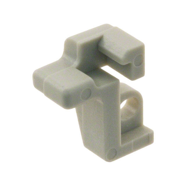
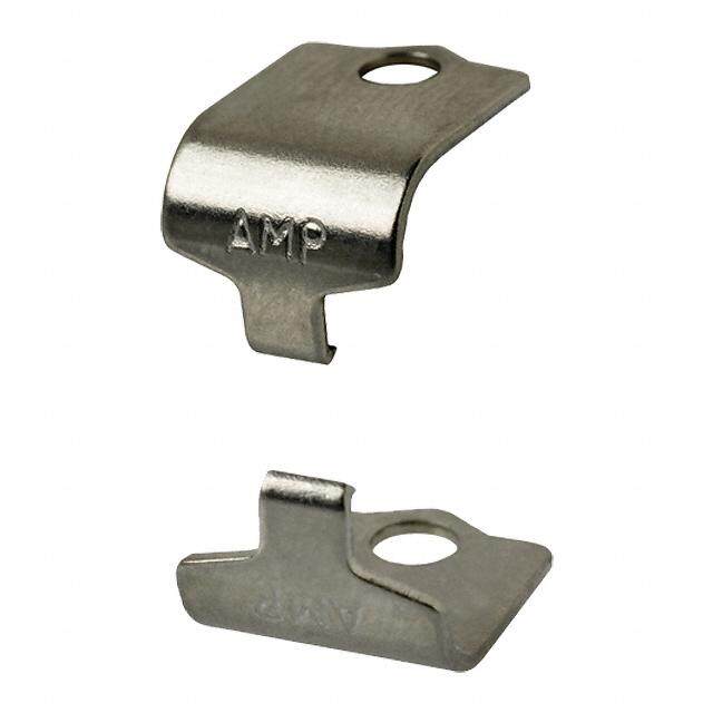
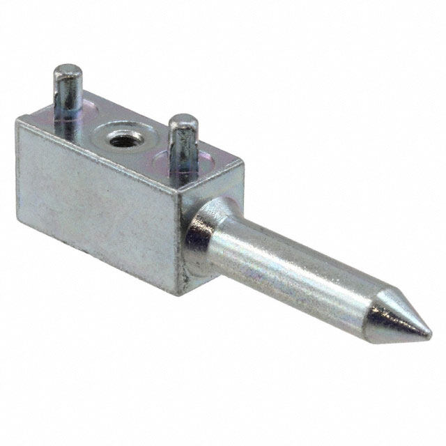
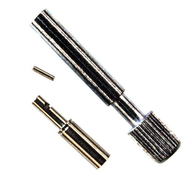
| 描述 | LOCKING SPRING MALE KIT=2PCS机架和面板连接器 SERIES M LOCK SPRING |
| 产品分类 | |
| 品牌 | TE Connectivity |
| 产品手册 | http://www.te.com/catalog/pn/en/201921-1?RQPN=201921-1 |
| 产品图片 |
|
| rohs | 符合RoHS无铅 / 符合限制有害物质指令(RoHS)规范要求 |
| 产品系列 | 机架和面板连接器,TE Connectivity 201921-1M, AMP |
| 数据手册 | http://www.te.com/commerce/DocumentDelivery/DDEController?Action=srchrtrv&DocNm=201921&DocType=Customer+Drawing&DocLang=English |
| 产品型号 | 201921-1 |
| RoHS指令信息 | http://www.te.com/commerce/alt/SinglePartSearch.do?PN=201921-1&dest=stmt点击此处下载产品Datasheet |
| 产品目录页面 | |
| 产品种类 | 机架和面板连接器 |
| 产品类型 | Connectors |
| 位置数量 | 4 |
| 其它名称 | 201921-1-ND |
| 包装 | 散装 |
| 商标 | TE Connectivity |
| 外壳材料 | - |
| 安装风格 | Through Hole |
| 工厂包装数量 | 50 |
| 标准包装 | 50 |
| 端接类型 | Crimp |
| 系列 | M Series |
| 节距 | 2.54 mm |
| 规格 | 锁定 |
| 触点材料 | Spring Steel |
| 触点电镀 | Nickel |
| 触点类型 | Pin (Male) |
| 配件类型 | 弹簧销 |
| 配套产品 | /product-detail/zh/201922-1/A30213-ND/299356 |
| 配套使用产品/相关产品 | M 系列 |
| 配用 | /product-detail/zh/201356-3/A112958-ND/2283373/product-detail/zh/202758-3/202758-3-ND/1153153/product-detail/zh/200346-4/200346-4-ND/1149878/product-detail/zh/202757-3/202757-3-ND/1136598/product-detail/zh/201298-3/201298-3-ND/1131072/product-detail/zh/202758-1/A30139-ND/679841/product-detail/zh/201356-1/A30114-ND/679816/product-detail/zh/201355-1/A30184-ND/299366/product-detail/zh/201298-1/A30179-ND/299365/product-detail/zh/200346-2/A30151-ND/299327/product-detail/zh/202757-1/A30226-ND/292243 |


- 商务部:美国ITC正式对集成电路等产品启动337调查
- 曝三星4nm工艺存在良率问题 高通将骁龙8 Gen1或转产台积电
- 太阳诱电将投资9.5亿元在常州建新厂生产MLCC 预计2023年完工
- 英特尔发布欧洲新工厂建设计划 深化IDM 2.0 战略
- 台积电先进制程称霸业界 有大客户加持明年业绩稳了
- 达到5530亿美元!SIA预计今年全球半导体销售额将创下新高
- 英特尔拟将自动驾驶子公司Mobileye上市 估值或超500亿美元
- 三星加码芯片和SET,合并消费电子和移动部门,撤换高东真等 CEO
- 三星电子宣布重大人事变动 还合并消费电子和移动部门
- 海关总署:前11个月进口集成电路产品价值2.52万亿元 增长14.8%

PDF Datasheet 数据手册内容提取
RoHS Ready M Series Pin and Socket Connectors
NOTE: All part numbers AMP M Series are RoHS Compliant Pin and Socket Connectors M Series Connectors Product Facts Standard Housings • Most connectors intermate- able with connectors made to MIL-C-28748 require- ments • Wide range of connector styles and sizes: standard connectors (unloaded), posted connectors (pre- loaded) and special applica- tion connectors (unloaded) • Complete line of accessory hardware for fastening, pro- tecting, guiding, shielding, strain relief and keying • A variety of contacts: signal, power, coaxial and posted versions - many are interchangeable and can be intermixed in the same con- nector housing • Full complement of applica- Posted Connectors tion tooling for wire crimp and posted terminations - hand tools, semiautomatic tooling and fully automatic machines provide highly reliable, low cost termina- tions to meet production requirements Need More Information? Call the Technical Support Center: 1-800-522-6752. The Center is staffed with specialists well versed in all AMP products and applica- tion tooling. The Center can provide you with: • Technical Support • Catalogs • Technical Documents • Product Samples • AMP FAX Service Product Information Faxed Special Application Connectors Immediately • Authorized Distributor Locations Specifications subject to change. Consult Tyco Electronics Corporation for lat- est design specifications. ©1968, 1970, 1972, 1974, 1978, 1985, 1990, 1996, 2001 and 2008 by Tyco Electronics Corpora- tion. All Rights Reserved. AMP, AMP FAX, AMPOMATOR, AMP-O-LECTRIC, AMP-O-MATIC, AMP-TAPETRONIC, CERTI-CRIMP, COAXICON, LGH, POWERBAND, PRO-CRIMPER, RAYCHEM, TERMI-POINT and Tyco are trademarks. Other products, logos, and company names mentioned herein may be trademarks of their respective owners. 2 Catalog 82003 Dimensions are in millimeters Dimensions are shown for USA: 1-800-522-6752 South America: 55-11-3611-1514 Revised 06-08 and inches unless otherwise reference purposes only. Canada: 1-905-470-4425 Hong Kong: 852-2735-1628 specified. Values in brackets are Specifications subject Mexico: 01-800-733-8926 Japan: 81-44-844-8013 www.tycoelectronics.com equivalent U.S. Customary Units. to change. C. America: 52-55-5-729-0425 UK: 44-141-810-8967
NOTE: All part numbers AMP M Series are RoHS Compliant Pin and Socket Connectors Table of Contents Product Facts. . . . . . . . . . . . . . . . . . . . . . . . . . . . . . . . . . . . . . . . 2 Introduction . . . . . . . . . . . . . . . . . . . . . . . . . . . . . . . . . . . . . . 4, 5 Material Specifications . . . . . . . . . . . . . . . . . . . . . . . . . . . . . . . . . . 6 Current Carrying Capabilities . . . . . . . . . . . . . . . . . . . . . . . . . . . . .7, 8 How to Use this Catalog . . . . . . . . . . . . . . . . . . . . . . . . . . . . . . . . . 9 Connector/Hardware Selection Guide (for Typical Applications) Cable-to-Cable .........................................................10-17 Cable-to-Panel ......................................................... 18-25 Contacts (Description of Types) . . . . . . . . . . . . . . . . . . . . . . . . . . 26-29 Signal Contacts Type II, Crimp, Snap-In. . . . . . . . . . . . . . . . . . . . . . . . . . . . . . . . . . 30 Type III+, Crimp, Snap-In; Posted; Solder Versions . . . . . . . . . . . . . . . . 31-35 Power Contacts Type I, Crimp, Snap-In . . . . . . . . . . . . . . . . . . . . . . . . . . . . . . . . . . 36 High Current Type II and Type III+ (Screw Machine, Crimp, Snap-In). . . . . . . . 37 Type XII, Crimp, Snap-In. . . . . . . . . . . . . . . . . . . . . . . . . . . . . . . . . 38 Coaxial Contacts Subminiature, Crimp, Snap-In, Size 16 ................................... 39, 40 Miniature, Crimp, Snap-In, Size 12. . . . . . . . . . . . . . . . . . . . . . . . . . 41, 42 Standard Housings—Introduction. . . . . . . . . . . . . . . . . . . . . . . . . . . 44 6, 14, and 20-Positions. . . . . . . . . . . . . . . . . . . . . . . . . . . . . . . . . . 45 26, 34 and 36-Positions . . . . . . . . . . . . . . . . . . . . . . . . . . . . . . . 46, 47 41 and 50-Positions . . . . . . . . . . . . . . . . . . . . . . . . . . . . . . . . . 47, 48 75 and 104-Positions. . . . . . . . . . . . . . . . . . . . . . . . . . . . . . . . . . . 49 104 CF Positions (with Center Fastener) . . . . . . . . . . . . . . . . . . . . . . . 50 160 CF Positions (with Center Fastener) . . . . . . . . . . . . . . . . . . . . . . . 51 Posted Connectors—Introduction. . . . . . . . . . . . . . . . . . . . . . . . . . . 52 6, 14, 20 and 26-Positions. . . . . . . . . . . . . . . . . . . . . . . . . . . . . . 53, 54 34 and 50 Positions . . . . . . . . . . . . . . . . . . . . . . . . . . . . . . . . . 55, 56 75 and 104-Positions. . . . . . . . . . . . . . . . . . . . . . . . . . . . . . . . . . . 57 104 and 160 CF Positions (with Center Fastener) . . . . . . . . . . . . . . . . 58, 59 15, 36 and 50 Positions (.200 [5.08] Grid). . . . . . . . . . . . . . . . . . . . . 59, 60 Special Application Connectors—Introduction . . . . . . . . . . . . . . . . . . . 61 V.35 Special Application Connectors—Introduction . . . . . . . . . . . . . . . 62, 63 V.35 Printed Circuit Board Connectors. . . . . . . . . . . . . . . . . . . . . . . 64-67 V.35 Cable Connectors. . . . . . . . . . . . . . . . . . . . . . . . . . . . . . . . 68-71 12-Positions, High Current Connector (UL Voltage Rating: 1800 V) . . . . . . . . 72 29 CF Position Connector with Mixed Contacts (with Center Fastener). . . . . . 73 42-Positions, Connector with Mixed Contacts . . . . . . . . . . . . . . . . . . . . 74 20-Positions, High Voltage Connector (UL Voltage Rating: 1800 V). . . . . . . . 75 28-Positions, High Voltage Connector (UL Voltage Rating: 1800 V). . . . . . . . 76 14 and 34-Positions, Grounding Blocks and Fastening Hardware . . . . . . . . . 77 Hardware Fastening Hardware . . . . . . . . . . . . . . . . . . . . . . . . . . . . . . . . . 78-80 Guiding Hardware . . . . . . . . . . . . . . . . . . . . . . . . . . . . . . . . . . . . 81 Protective Hardware. . . . . . . . . . . . . . . . . . . . . . . . . . . . . . . . . 82-87 Strain Relief Hardware. . . . . . . . . . . . . . . . . . . . . . . . . . . . . . . . . . 88 Keying Hardware . . . . . . . . . . . . . . . . . . . . . . . . . . . . . . . . . . . . . 89 Application Tooling . . . . . . . . . . . . . . . . . . . . . . . . . . . . . . . . . 90, 95 Technical Documents . . . . . . . . . . . . . . . . . . . . . . . . . . . . . . . . 96, 97 Part Number Index . . . . . . . . . . . . . . . . . . . . . . . . . . . . . . . . . 98, 99 3 Catalog 82003 Dimensions are in millimeters Dimensions are shown for USA: 1-800-522-6752 South America: 55-11-3611-1514 Revised 06-08 and inches unless otherwise reference purposes only. Canada: 1-905-470-4425 Hong Kong: 852-2735-1628 specified. Values in brackets are Specifications subject Mexico: 01-800-733-8926 Japan: 81-44-844-8013 www.tycoelectronics.com equivalent U.S. Customary Units. to change. C. America: 52-55-5-729-0425 UK: 44-141-810-8967
NOTE: All part numbers AMP M Series are RoHS Compliant Pin and Socket Connectors Introduction AMP M Series connectors are contacts. A description of each one of the most versatile and contact type is presented on complete pin and socket con- pages 26 through 29. nector lines available today. Application tooling for these contacts is described on pages From the basic molded plastic 90 and 91. housing, a connector can be built up with a wide choice of Standard connectors contacts and hardware to Standard connectors are com- serve in applications ranging prised of unloaded housings from sophisticated computers, that accept a variety of crimp, medical instrumentation and solder and posted contacts. All military ground support standard connector housings equipment to rugged truck will accept pins and/or sockets, transmissions. permitting various combina- How this M Series tions of contact loading. catalog is divided Standard connectors are described on pages The M Series catalog is 44 through 51. divided into six categories: • Application section Posted connectors • Contacts/Tooling Posted connectors are • Standard Connector preloaded with post-type con- Housings tacts that accept • Posted Connector Housings TERMI-POINT Clip or • Special Application wrap-type terminations. Connector Housings All posted connectors are • Hardware described on pages 52 through Following is a brief summary 60. of each of the six categories. Special Application connec- Knowing what you need tors to meet your application Connectors for special applica- is made easy tion are available in Eight applications have been the following configurations: illustrated with selection • V.35 charts from pages 10 through • High Current 25. These charts will assist you • Mixed Contact Connectors to select the appropriate con- • High Voltage nector housing as well as the • RFI/EMI Shielded necessary hardware. Each • Grounding Blocks base part number is listed in Special Application Connectors the numerical index on pages are described on pages 61 94, 95 in order to find com- through 77. plete information about a particular part. The right hardware for the entire M Series connector line Contacts of various types provide different functions in Hardware is available to provide M Series connector housings fastening, protection, shielding, guiding, strain relief and keying Included are contacts for sig- capabilities for the entire nal and power applications, for M Series connector line. coaxial cable and posted ver- Application charts for properly sions for backpanel wiring. A selecting hardware are pre- full complement of application sented on pages 10 through 25. tooling is available to meet Detailed information on hard- any production requirement ware is located on pages 78 for terminating the crimp-type through 89. contacts and wiring posted 4 Catalog 82003 Dimensions are in millimeters Dimensions are shown for USA: 1-800-522-6752 South America: 55-11-3611-1514 Revised 06-08 and inches unless otherwise reference purposes only. Canada: 1-905-470-4425 Hong Kong: 852-2735-1628 specified. Values in brackets are Specifications subject Mexico: 01-800-733-8926 Japan: 81-44-844-8013 www.tycoelectronics.com equivalent U.S. Customary Units. to change. C. America: 52-55-5-729-0425 UK: 44-141-810-8967
NOTE: All part numbers AMP M Series are RoHS Compliant Pin and Socket Connectors Introduction (Continued) What makes the M Series A - Determine Connector Type– connector line so versatile This decision is based on the and special for a wide variety selected contact types, circuit of applications? density requirements and, if posted connectors are desired, • Compatibility–Most in-plant production capabilities connectors intermateable for wiring connectors using with connectors made to hand tools or semiautomatic MIL-C-28748 requirements. tooling. Detailed specifications • Wide range–Choice of con- of the various M Series connec- nector styles and sizes: tors are presented on the standard connectors following pages: Standard con- (unloaded), posted connec- nectors (pages 44 through 51), tors (preloaded) and special Posted connectors (pages 52 application connectors. through 60), Special • Complete line–Full line of Application connectors (pages accessory hardware for fas- 61 through 77). tening, protecting, guiding, B - Determine Hardware– strain relief and keying. This decision is based on the selected connector types, and • Variety of contacts–Signal, the individual application power, coaxial, and posted requirements for fastening, pro- versions—many are inter- tection, shielding, guiding, strain changeable and can be relief and keying. To assist cus- intermixed in the same con- tomers in determining the nector housing. proper hardware to use, hard- • Full complement of applica- ware selection information has tion tooling–For wire crimp been formulated for each con- and posted terminationshand nector type. This information is tools, semiautomatic tooling located on pages 10 through 25. and fully automatic machines Complete specifications of each provide highly reliable, low hardware component are pre- cost terminations to meet sented in the Hard-ware section production requirements. of the catalog (pages 78 How to choose the appropri- through 89). ate connector/contact/ C - Determine Contact Type – hardware combination This decision is based on wire Choosing the appropriate con- size(s) and reliability and cost nector/contact/hardware requirements of an application, combination is essential to the as well as the customer’s in- proper function of any plant production capabilities. AMP M Series connector. First, Complete specifications, includ- a customer must evaluate ing accepted wire sizes and each individual application available platings of all pin and with regards to: wire size(s); socket contacts, are presented number of circuits; available in the Contacts section of the space; fastening methods; and catalog (pages 30 through 43). needs for protection, shielding, Application tooling for crimp- guiding, strain relief and key- and post-type contacts is ing. Then, the customer must presented on pages 90 and 91). consider the following factors to make the appropriate selec- tion of M Series connectors and related components. 5 Catalog 82003 Dimensions are in millimeters Dimensions are shown for USA: 1-800-522-6752 South America: 55-11-3611-1514 Revised 06-08 and inches unless otherwise reference purposes only. Canada: 1-905-470-4425 Hong Kong: 852-2735-1628 specified. Values in brackets are Specifications subject Mexico: 01-800-733-8926 Japan: 81-44-844-8013 www.tycoelectronics.com equivalent U.S. Customary Units. to change. C. America: 52-55-5-729-0425 UK: 44-141-810-8967
NOTE: All part numbers AMP M Series are RoHS Compliant Pin and Socket Connectors Material Specifications Contacts MIL-M-14, Type CFG. The per- Performance Data formance characteristics of The material composition and Temperature Rating: construction of AMP contacts these housings make them an Phenolic Housings, encompass varying price excellent choice –55°C to +150°C for applications in which Diallyl Phthalate Housings, –65°C ranges and performance char- s exceptional resistance to to +125°C n acteristics. Specific materials o and available platings and acids, alkalies or solvents Polyester, –55°C to +130°C ti is not of prime concern. Flammability Ratings: UL94V-0 a plating thicknesses of each c Polyester housings are Dielectric Withstanding i contact type are provided on f molded from a high tempera- Voltage (at sea level): eci itnhdei vCidounatal ccto snetacctito pn a(gpeasg eins ture thermoplastic material Type II Contacts, 1500 VAC, RMS p per ASTM D3220. Polyester Type III+ Contacts, 900 VAC, RMS S 30 thru 43). A brief descrip- l tion of each contact type is housings provide the high Durability (Mating/Unmating): a temperature characteristics of Types II and III+ Contacts, Gold ri presented on pages 26 Plated: 500 cycles; e diallyl phthalate and phenolic, t through 29. Also, typical per- Types II and III+ Contacts, a but with a higher impact M formance data of M Series Tin Plated: strength. connectors and contacts is 50 cycles; Type I Contacts, shown below. Hardware Gold Plated: 100 cycles Housings A variety of materials such as plated steel, stainless steel Note: For detailed information on the M Series connector housings above performance data and further and aluminum, are used in are made of either diallyl information on other performance data the construction of such as Insulation Resistance, Thermal phthalate (blue), general pur- M Series connector hardware. Shock, Moisture Resistance, Vibration pose phenolic (black) and Physical Shock, request or polyester (black). This provides for the proper AMP Product Specification No. operation and durability of 108-10001. Diallyl phthalate housings are each hardware component, molded of material per while offering a choice of MIL-M-14, Type SDG. These economies to satisfy particu- housings are ideally suited for lar application requirements. use where adverse environ- The materials of each hard- mental conditions are an ware component are important factor. Their advan- specified on the individual tages include exceptional hardware component pages stability; excellent resistance in the Hardware section to acids, alkalies and solvents; (pages 78 through 89). low moisture absorption; and good dielectric strength. Phenolic housings are molded of material per • Recognized under the Component Program of Underwriters Laboratories Inc. for 250 volts, File No. E28476 R • Certified by Canadian Standards Association, File No. LR 7189 6 Catalog 82003 Dimensions are in millimeters Dimensions are shown for USA: 1-800-522-6752 South America: 55-11-3611-1514 Revised 06-08 and inches unless otherwise reference purposes only. Canada: 1-905-470-4425 Hong Kong: 852-2735-1628 specified. Values in brackets are Specifications subject Mexico: 01-800-733-8926 Japan: 81-44-844-8013 www.tycoelectronics.com equivalent U.S. Customary Units. to change. C. America: 52-55-5-729-0425 UK: 44-141-810-8967
NOTE: All part numbers AMP M Series are RoHS Compliant Pin and Socket Connectors Contract Carrying Capabilities The total current capacity of CONTACT CURRENT GUIDE Maximum Current (Amperes) each contact in a given con- 75 nector is dependent upon the Type XII Upgrade heat rise resulting from the combination of electrical 60 Size 8 Upgrade 60 loads of the contacts in the 56 .125 POWERBAND connector arrangement and 50 Contact the maximum ambient tem- perature in which the 45 45 Size 8 C u connector will be operating. r Caution must be taken to 35 Type XII re ensure that this combination n 30 Type I, Type II/III+ t of conditions does not cause 23 Upgrade C tthhee icnotnenrneaclt oterm top eerxacteuerde othf e TTyyppee IIIIII++, PToysptee dII, arr maximum operating temper- 15 13 11.85 in ature of the housing material. Size 20 Upgrade g Several variables which must 7.5 C be considered when deter- 20 DF ap 0 mining this maximum current a capability for your applica- b i tion are: li t i e s Wire Size - Larger wire will Connector Size - In general, Current Load Distribution - Ambient Temperature - carry more current since it with more circuits in a con- Spreading those lines with With higher ambient has less internal resistance nector, less current per greater current loads temperatures, less current to current flow and gener- contact can be carried. through-out the connector, can be carried. ates less heat. The wire also particularly around the conducts heat away from outer perimeter, will the connector. enhance heat dissipation. Current Rating Verification Practical current-carrying Temperature containing 50% current-carry- Can a contact rated at 10 capacity is not an absolute, One other factor influencing ing contacts will permit higher amps carry 10 amps? but an application-dependent current levels is the maximum currents (per contact) than a Maybe yes, but probably not. condition. operating temperature, for connector will at 75% loading. The reason lies in the test New Method Simplifies example, 105°C. If the appli- The loading percentage conditions used to rate the cation has a high ambient assumes an even distribution contact. If these conditions Ratings temperature (over 75°C) the of contacts within the housing. do not adequately reflect the To help the designer set the contact’s T-rise is limited by If all 10 contacts are grouped application conditions, the appropriate current level, the maximum operating tem- together in one section of a actual allowable current lev- Tyco has developed a perature. For example, an 20-position els may be lower than method of specifying cur- application temperature of connector, the loading density specified levels. For example, rent-carrying capacity. This 90°C limits the contact T-rise may approach 100%. many manufacturers, includ- method takes into account to 15°C. Since current pro- The Importance of EODL ing Tyco, test a single contact the various application fac- duces heat (the I2R law), the in air. This gives an accurate tors that influence current current must be lowered to As stated, T-rise in a contact measure of the basic current- rating. limit the T-rise. depends on both resistance and current. As it ages, a con- carrying capacity of the The method can be summa- A contact’s T-rise depends tact’s resistance will increase. contact. Use the contact rized as follows: not only on its I2R Joule heat- The contact designer will alone in air and it can cer- tainly carry 10 amperes. Use The contact is aged to ing, but also on its ability to specify a maximum resistance EODL conditions by durabil- dissipate the heat. Consider a for the contact, this level is the it in a multi-position connec- ity cycling, thermal cycling, contact in a multi-contact end-of-design-life resistance. tor surrounded by other and environmental expo- housing. Joule heating in Before the contact is tested current-carrying contacts or sure. multiple contacts will raise for current, Tyco subjects it to in high ambient temperatures, and the contact should carry The contact’s resistance the local ambient tempera- a sequence of tests that exer- less current. stability is verified. ture. Since the contact will cises the major failure not be able to dissipate its mechanisms and thereby sim- Similarly, as the contact ages The current necessary to own heat as well by convec- ulates EODL conditions. and stress relaxation, environ- produce the specified tem- tion, the maximum T-rise will Conditioning includes mating mental cycling, and other perature rise is measured. be realized at a lower current cycling, industrial mixed-flow- degradation factors take their This T-rise is usually 30°C. level. Conse-quently, the ing gases, humidity and toll, the contact’s current- A rating factor is deter- allowable current level must tempera-ture cycling, and carrying capacity decreases. mined to allow derating of be lower to maintain an vibration to sequentially A prudent design must set multiple contacts in the acceptable T-rise. introduce wear, corrosion, current levels for such end-of- same housing and for differ- For a given connector, the stress relaxation, and design-life (EODL) conditions. ent conductor sizes. current level will be set by the mechanical disturbance. loading density. A connector 7 Catalog 82003 Dimensions are in millimeters Dimensions are shown for USA: 1-800-522-6752 South America: 55-11-3611-1514 Revised 06-08 and inches unless otherwise reference purposes only. Canada: 1-905-470-4425 Hong Kong: 852-2735-1628 specified. Values in brackets are Specifications subject Mexico: 01-800-733-8926 Japan: 81-44-844-8013 www.tycoelectronics.com equivalent U.S. Customary Units. to change. C. America: 52-55-5-729-0425 UK: 44-141-810-8967
NOTE: All part numbers AMP M Series are RoHS Compliant Pin and Socket Connectors Presentation - Example of New Current Rating Format The presentation of current- car- Note: Data is not typical of a spe- rying capacity in AMP product cific M Series connector specifications includes two parts: configuration. For specific 15 current rating information based Single Contact First, a base curve showing cur- on % connector loading, contact 18 AWG rent levels versus T-rise for a single circuit and the largest wire Tyco Electronics. s) e size (See figure 1). This repre- To demonstrate the method of 10 er p s sents the maximum current specifying current, consider the Am apabilitie ccattohmaue pr7bv a5aieecm° nCiitsoty, uua tohnsnfuetd ta o3htllhf0ey ec ° cfnuCloa r drnTter -tuonrappitcs, set ta .o olnTi fm7dhf.5e iUt° sCp fa5hwon0oilr lu%aoesm.w ilnoibngaige,d na iantnp gdtpe o2mlifc0 pac AetoirWonatntaGu ccr oe[ts0 no .di6fn im t6ti5ohm°neC2s ;,] a 5 Current Rating ( C above 75°C the current must be From Figure 1, the base current g reduced to keep the combina- rating is 14 ampere with 18 AWG yin tainodn To-fr aisme bfrioemnt etexmcepeedriantgu rteh e [0.8mm2] wire. 0 10 20 30 40 50 60 70 80 90 100 0 rr maximum operating tempera- Figure 2, the rating factor for Ambient Temperature (C) a ture of 105°C. 50% loading and 20 AWG Graph shows the relationship between base current, ambient t C Next are rating factors; a table [0.6mm2] wire is 0.68. temperature, and contact T-rise. n e of multipliers to account for The specific rating for this appli- r connector loading and for cation is the product of the r u smaller wire sizes (See figure 2). base rating and the rating factor: C The designer first determines 14 x 0.68 = 9.5 ampere AWG the base current for the ambi- Each of the contacts can carry ent conditions of the 9.5 ampere. 18 20 22 24 26 application; then multiplies this base current by the rating fac- However, if the ambient tem- tors to find the current level for perature is 80°C the allowable Single 1 .83 .69 .59 .50 the application’s loading factor T-rise becomes 25°C. The base and wire size. current must be lowered to 12.8 ampere so that the 105°C maxi- mum operating temperature is 30% .97 .80 .66 .57 .49 not exceeded. The current rat- Practical Values ing then becomes: g n The current-rating method gives 12.8 x 0.68 = 8.7 ampere. adi 50% .83 .68 .57 .48 .42 o designers practical values appli- L cable to their applications. While contact under varying conditions % the specified current levels for a of temperature, connector load- 70% .65 .53 .45 .38 .33 contact may be lower than for ing, and wire size. other testing methods, they are Specific current-carrying data more realistic and simplify the based on EOL and % loading system design process. is available from Tyco Electronics 100% .55 .45 .38 .32 .28 “Spec-manship” is replaced Corporation. Please contact your by a realistic assessment of the local Sales Engineer or call Tyco current-carrying capacity of a Electronics Corporation. Figure 2 Rating factors allow the base current to be adjusted for various Connector/Contact connector loading and wire sizes. Acceptability As previously stated, choosing the appropriate connector/contact combination is fundamental to the Contact Selection Chart successful function of all connec- tors. The Selection Chart, shown at Connector High Current Posted High Current Sub-Mini right, is designed to simplify your Type Type I Type II Type II/III Type III+ Type III+ Type XII Type XII Mini-coax Coax choice of connectors and their M Series acceptable contacts. Once you M Series have selected the wire size, cur- Special rent-carrying capacity need, number of positions required, and the type of contacts needed in your choice of connector, refer to this matrix for a quick look at exactly what is acceptable in a given connector type. 8 Catalog 82003 Dimensions are in millimeters Dimensions are shown for USA: 1-800-522-6752 South America: 55-11-3611-1514 Revised 06-08 and inches unless otherwise reference purposes only. Canada: 1-905-470-4425 Hong Kong: 852-2735-1628 specified. Values in brackets are Specifications subject Mexico: 01-800-733-8926 Japan: 81-44-844-8013 www.tycoelectronics.com equivalent U.S. Customary Units. to change. C. America: 52-55-5-729-0425 UK: 44-141-810-8967
NOTE: All part numbers AMP M Series are RoHS Compliant Pin and Socket Connectors How to Use the M Series Connector Catalog The information in this indicated. Noted under each catalog has been arranged to Special Application assist the customer in select- Connector is the standard ing the connector and size hardware used for that associated hardware that connector. Substitute into the best satisfies their require- appropriate column of the ments. component selection charts. Four cable-to-cable and four The main portion of the cable-to-panel applications catalog is divided into five H utilizing the various types of basic sections: contacts, o fastening, guiding and pro- standard connectors, posted w tective hardware have been connectors, special applica- t o illustrated on pages 10 tion connectors and U through 25. hardware. These sections s contain brief descriptions, e Aatfete arp spellieccattiinogn tthoe f iat pap ro-pri- dimensions and other th technical information. The is particular requirement, refer remainder of the catalog con- C to the indicated pages for a component selection. tains application tooling ta information, a technical docu- l Posted connectors and ments list and a numerical og Special Application connec- index which references pages tors can be substituted for covering all cataloged part Standard Connectors where numbers. 9 Catalog 82003 Dimensions are in millimeters Dimensions are shown for USA: 1-800-522-6752 South America: 55-11-3611-1514 Revised 06-08 and inches unless otherwise reference purposes only. Canada: 1-905-470-4425 Hong Kong: 852-2735-1628 specified. Values in brackets are Specifications subject Mexico: 01-800-733-8926 Japan: 81-44-844-8013 www.tycoelectronics.com equivalent U.S. Customary Units. to change. C. America: 52-55-5-729-0425 UK: 44-141-810-8967
NOTE: All part numbers AMP M Series are RoHS Compliant Pin and Socket Connectors Cable-to-Cable Application A Locking Springs Sockets Featured Hardware Housings Strain Relief Clamps Locking Springs Pin Hoods Pin Hoods e Guide Hardware Pins d i u G n Guide Hardware o i t c e l e S e ar Strain Relief Clamps w d r a H / r o t c e n n o C Number of Positions Component Description 6 14 20 26 34 Plug Block } 202758-1 201355-1 201356-1 201359-1 1-201357-1 Phenolic Receptacle Block 202757-1 201298-1 200346-2 200512-2 200838-2 STANDARD Plug Block } 202758-3 — 201356-3 201359-3 201357-3 HOUSINGS Receptacle Block Diallyl Phthalate 202757-3 201298-3 200346-4 200512-3 200838-3 Pages 44 to 51 Plug Block } — — — — 2013800-1 Polyester Receptacle Block — — — — 200802-1 STRAIN Long } N ickel Plated Steel — 201843-3 — 201845-2 201846-5 RELIEF Short 203432-1 200686-4 — 201229-5 — CLAMPS Long } — — — — — Page 88 Short Stainless Steel — — 201237-2 — 201224-7 Center Male } 200389-2 200389-2 200389-2 200389-2 200389-2 GUIDE Center Female 200390-9 200390-9 200390-9 200390-9 200390-9 HARDWARE Stainless Steel Page 81 Corner Male — — — — 1-200833-1 Corner Female — — — — 1-200835-1 Male—Nickel Plated Spring Steel 201921-1 201921-1 201921-1 201923-1 201925-1 LOCKING SPRINGS1 201918-1 Page 80 Female—Stainless Steel 201922-1 201922-1 201922-1 201926-1 (Single Spring) Internal Open End Nickel Plated Steel 204258-6 201363-4 — 201785-4 201786-4 PIN HOODS Internal Closed End Nickel Plated Steel — — — — — Pages 82 and 83 External Closed End Al Iridite — — — — — External Closed End Nickel Plated Steel — — — — — 1Each part number contains two locking springs. Order one male and one female for each mated pair of connectors. 10 Catalog 82003 Dimensions are in millimeters Dimensions are shown for USA: 1-800-522-6752 South America: 55-11-3611-1514 Revised 06-08 and inches unless otherwise reference purposes only. Canada: 1-905-470-4425 Hong Kong: 852-2735-1628 specified. Values in brackets are Specifications subject Mexico: 01-800-733-8926 Japan: 81-44-844-8013 www.tycoelectronics.com equivalent U.S. Customary Units. to change. C. America: 52-55-5-729-0425 UK: 44-141-810-8967
NOTE: All part numbers AMP M Series are RoHS Compliant Pin and Socket Connectors Cable-to-Cable (Continued) 1. Confirm that Application A (at left) most closely meets Special application housings may be substituted your requirements. (Other applications are shown on for these standard housings. See Special Application pages 12 through 25.) Section. 2. Find the appropriate column for the number of positions required. This cable-to-cable application utilizes locking springs, strain relief clamps, a pin hood for pin protection and guide hard- 3. Select part numbers required for the application listed ware. in the column below the number of positions. The 34 and 50 position connectors can be used with either 3. If a part number is not listed for a particular item, it is center or corner guide hardware. If center guide hardware is not available. used, an additional four 4-40 screws, nuts and lockwashers are 3. If more than one part number is listed for a particular required to secure the locking springs. Corner guides require C hardware item, choose the one which best fits your four guide pins and four guide sockets for each mated pair of o n application. connectors. n e 4. Dimensional information is available on the indicated ct o pages under description column. r / H 5. Select Contacts: Type II (page 30), Type III+ (pages 31 a through 35) or Subminiature Coaxial (pages 40, 41). rd w a r e S e le c t io n G u id e Number of Positions Component Description 41 50 75 104 104 CF 160 CF 202135-2 201358-1 — — — — Plug Block } Phenolic 201302-1 200277-2 — — — — Receptacle Block 202135-4 201358-3 — — — — Plug Block } STANDARD 201302-3 200277-4 — — — — Receptacle Block Diallyl Phthalate HOUSINGS Pages 44 to 51 — — — — 1-201692-6 — Plug Block } Polyester — — — — — — Receptacle Block — — — — — — Long } Nickel Plated Steel STRAIN — 201182-4 — — — — Short RELIEF 201766-1 201847-1 — — — — Long } CLAMPS — — — — — — Short Stainless Steel Page 88 200389-2 200389-2 — — — — Center Male } GUIDE 200390-9 200390-9 — — — — Center Female Stainless Steel HARDWARE — 1-200833-1 — — — — Corner Male Page 81 — 1-200835-1 — — — — Corner Female 201921-1 201925-1 — — — — Male—Nickel Plated Spring Steel LOCKING SPRINGS1 201922-1 201926-1 — — — — Female—Stainless Steel Page 80 — — — — — — Internal Open End Nickel Plated Steel — — — — — — Internal Closed End Nickel Plated Steel PIN HOODS — — — — — — External Closed End Al Iridite Pages 82 and 83 — — — — — — External Closed End Nickel Plated Steel 11 Catalog 82003 Dimensions are in millimeters Dimensions are shown for USA: 1-800-522-6752 South America: 55-11-3611-1514 Revised 06-08 and inches unless otherwise reference purposes only. Canada: 1-905-470-4425 Hong Kong: 852-2735-1628 specified. Values in brackets are Specifications subject Mexico: 01-800-733-8926 Japan: 81-44-844-8013 www.tycoelectronics.com equivalent U.S. Customary Units. to change. C. America: 52-55-5-729-0425 UK: 44-141-810-8967
NOTE: All part numbers AMP M Series are RoHS Compliant Pin and Socket Connectors Cable-to-Cable (Continued) Application B Sockets Featured Hardware Strain Relief Clamps Guide Hardware Pin Hoods Jackscrews Guide Hardware e d i Pin Hoods u G Pins n o i t c e l Jackscrews e Housings S e r a w d r a H Strain Relief Clamps / r o t c e n n o C Number of Positions Component Description 6 14 20 26 34 Plug Block } 202758-1 201355-1 201356-1 201359-1 1-201357-1 Phenolic Receptacle Block 202757-1 201298-1 200346-2 200512-2 200838-2 STANDARD Plug Block } 202758-3 — 201356-3 201359-3 201357-3 HOUSINGS Receptacle Block Diallyl Phthalate 202757-3 201298-3 200346-4 200512-3 200838-3 Pages 44 to 51 Plug Block } — — — — 213800-1 Polyester Receptacle Block — — — — 213802-1 STRAIN Long } Nickel Plated Steel — 201843-3 — 201845-2 201846-5 RELIEF Short 203432-1 200686-4 — 201229-5 — CLAMPS Long } — — — — — Page 88 Short Stainless Steel — — 201237-2 — 201224-7 Fixed Male } 201092-4 201092-4 201092-4 201092-4 201092-4 Stainless Steel Fixed Female 201089-4 201089-4 201089-4 201089-4 201089-4 } Long-Long Male — — — — — JACKSCREWS1 Long-Long Female — — — — — Pages 78 and 79 Long Male Tip: — — — — — Stainless Steel Long Female — — — — — Body: Short-Short Male Die Cast Zinc 201827-1 201827-1 201827-1 201827-1 201827-1 Short-Short Female 201828-1 201828-1 201828-1 201828-1 201828-1 Center Male } — — — — — GUIDE Center Female — — — — — HARDWARE Stainless Steel Page 81 Corner Male — — — — 1-200833-1 Corner Female — — — — 1-200835-1 Internal Open End Nickel Plated Steel 204258-6 201363-4 — 201785-4 201786-4 PIN HOODS Internal Closed End Nickel Plated Steel — — — — 202434-4 Pages 82 and 83 External Closed End Al Iridite — — — 201349-2 201350-2 External Closed End Nickel Plated Steel — — — — — 1Listed Jackscrews have 6-32 single lead threads. For corresponding Jackscrews with 6-32 double lead threads, refer to pages 78 and 79. 12 Catalog 82003 Dimensions are in millimeters Dimensions are shown for USA: 1-800-522-6752 South America: 55-11-3611-1514 Revised 06-08 and inches unless otherwise reference purposes only. Canada: 1-905-470-4425 Hong Kong: 852-2735-1628 specified. Values in brackets are Specifications subject Mexico: 01-800-733-8926 Japan: 81-44-844-8013 www.tycoelectronics.com equivalent U.S. Customary Units. to change. C. America: 52-55-5-729-0425 UK: 44-141-810-8967
NOTE: All part numbers AMP M Series are RoHS Compliant Pin and Socket Connectors Cable-to-Cable (Continued) 1. Confirm that Application B (at left) most closely meets Special application housings may be substituted your requirements. (Other applications are shown on for these standard housings. See Special Application pages 10-11 and 14 through 25.) Section. 2. Find the appropriate column for the number of positions required. This cable-to-cable application utilizes jackscrews, strain relief clamps and guide hardware. A pin hood is provided for pin 3. Select part numbers required for the application listed protection. Sizes 6, 14, 20, 26, and 41 do not use guide hard- in the column below the number of positions. ware with this application. If a part number is not listed for a particular item, it is not available. If more than one part number is listed for a particular C hardware item, choose the one which best fits your appli- o cation. nn e 4. Dimensional information is available on the indicated c t pages under description column. o r / 5. Select Contacts: Type II (page 30), Type III+ (pages 31 H a through 35) or Subminiature Coaxial (pages 40, 41). r d w a r e S e le c t io n G u id e Number of Positions Component Description 41 50 75 104 104 CF 160 CF 202135-2 201358-1 201310-1 201345-1 — — Plug Block } Phenolic 201302-1 200277-2 201311-1 201037-1 — — Receptacle Block 202135-4 201358-3 201310-3 201345-2 — — Plug Block } STANDARD Diallyl Phthalate HOUSINGS 201302-3 200277-4 201311-3 — — — Receptacle Block Pages 44 to 51 — — — — 1-201692-6 — Plug Block } Polyester — — — — — — Receptacle Block — — — 201849-1 — — Long } Nickel Plated Steel STRAIN — 201182-4 200730-4 — — — Short RELIEF 201766-1 201847-1 201848-5 — — — Long } CLAMPS — — — — — — Short Stainless Steel Page 88 201092-4 201092-4 201092-4 201092-4 — — Fixed Male } Stainless Steel 201089-4 201089-4 201089-4 201089-4 — — Fixed Female } — — — — — — Long-Long Male — — — — — — Long-Long Female JACKSCREWS1 — — — — — — Long Male Tip: Pages 78 and 79 — — — — — — Long Female Stainless Steel Body: 201827-1 201827-1 201827-1 201827-1 — — Short-Short Male Die Cast Zinc 201828-1 201828-1 201828-1 201828-1 — — Short-Short Female } — — — — — — Center Male GUIDE — — — — — — Center Female Stainless Steel HARDWARE — 1-200833-1 1-201046-2 1-201046-2 — — Corner Male Page 81 — 1-200835-1 201047-2 201047-2 — — Corner Female — — — — — — Internal Open End Nickel Plated Steel — 202394-2 201369-4 201364-4 — — Internal Closed End Nickel Plated Steel PIN HOODS — — — — — — External Closed End Al Iridite Pages 82 and 83 — 201390-5 201368-4 201346-4 — — External Closed End Nickel Plated Steel 13 Catalog 82003 Dimensions are in millimeters Dimensions are shown for USA: 1-800-522-6752 South America: 55-11-3611-1514 Revised 06-08 and inches unless otherwise reference purposes only. Canada: 1-905-470-4425 Hong Kong: 852-2735-1628 specified. Values in brackets are Specifications subject Mexico: 01-800-733-8926 Japan: 81-44-844-8013 www.tycoelectronics.com equivalent U.S. Customary Units. to change. C. America: 52-55-5-729-0425 UK: 44-141-810-8967
NOTE: All part numbers AMP M Series are RoHS Compliant Pin and Socket Connectors Cable-to-Cable (Continued) Application C Locking Springs Sockets Housings Featured Hardware Shields (One-piece) Pin Hoods Pin Hoods Locking Springs Pins Guide Hardware e d i u G Guide Hardware n o i t c e l e S e Shields r a w d r a H / r o t c e n n o C Number of Positions Component Description 6 14 20 26 34 Plug Block } — 201355-1 201356-1 201359-1 1-201357-1 Phenolic Receptacle Block — 201298-1 200346-2 200512-2 200838-2 STANDARD Plug Block } — — 201356-3 201359-3 201357-3 HOUSINGS Diallyl Phthalate Pages 44 to 51 Receptacle Block — 201298-3 200346-4 200512-3 200838-3 Plug Block } — — — — 213800-1 Polyester Receptacle Block — — — — 213802-1 180° Two- } Al Anodized — — — — — Piece Long Zinc Plated Steel — — — — — } Al Anodized — — — — — 180° Two- Zinc Plated Steel — — — — — Piece Short Zinc Plated Cast Al — — — — — } SHIELDS 90° Two-Piece Long — — — — — Pages 84 to 87 90° Two-Piece Short — — — — — 45° Two-Piece Short Nickel — — — — — 45° Two-Piece Deep Plated — — — — — 180° One-Piece Long Steel — 201378-2 — — 201384-2 180° One-Piece Short — 201360-2 201227-2 201169-2 201165-2 90° One-Piece Short — 201460-2 201468-2 201469-2 Center Male } — 200389-2 200389-2 200389-2 200389-2 GUIDE Center Female — 200390-2 200390-2 200390-2 200390-2 HARDWARE Stainless Steel Page 81 Corner Male — — — — 1-200833-1 Corner Female — — — — 1-200835-1 LOCKING SPRINGS1 Male—Nickel Plated Spring Steel — 201921-1 201921-1 201923-1 201925-1 Page 80 Female—Stainless Steel — 201922-1 201922-1 — 201926-1 Internal Open End Nickel Plated Steel — 201363-4 — 201785-4 201786-4 PIN HOODS Internal Closed End Nickel Plated Steel — — — — — Pages 82 and 83 External Closed End Al Iridite — — — — — External Closed End Nickel Plated Steel — — — — — 1Each part number contains two locking springs. Order one male and one female for each mated pair of connectors. 14 Catalog 82003 Dimensions are in millimeters Dimensions are shown for USA: 1-800-522-6752 South America: 55-11-3611-1514 Revised 06-08 and inches unless otherwise reference purposes only. Canada: 1-905-470-4425 Hong Kong: 852-2735-1628 specified. Values in brackets are Specifications subject Mexico: 01-800-733-8926 Japan: 81-44-844-8013 www.tycoelectronics.com equivalent U.S. Customary Units. to change. C. America: 52-55-5-729-0425 UK: 44-141-810-8967
NOTE: All part numbers AMP M Series are RoHS Compliant Pin and Socket Connectors Cable-to-Cable (Continued) 1. Confirm that Application C (at left) most closely meets Special application housings may be substituted your requirements. (Other applications are shown on for these standard housings. See Special Application pages 10-13 and 16 through 25.) Section. 2. Find the appropriate column for the number of positions required. This cable-to-cable application utilizes locking springs, 3. Select part numbers required for the application listed one- piece shields, a pin hood for pin protection and guide in the column below the number of positions. hardware. The shields are available with both 180° and 90° If a part number is not listed for a particular item, it is cable exits. The 180° shields are available in a long version not available. which provides pin protection in lieu of a pin hood. If more than one part number is listed for a particular A short shield and a pin hood or a long shield can be used on C hardware item, choose the one which best fits your appli- one side only of a mated pair of connectors. The mating con- o cation. nector must use a short shield. nn e 4. Dimensional information is available on the indicated The 34 and 50 position connectors can be used with either ct pages under description column. center or corner guide hardware. If center guides are used, an or / 5. Select Contacts: Type II (page 30), Type III+ (pages 31 additional four 4-40 screws are required to secure the locking H a through 35) or Subminiature Coaxial (pages 40, 41). springs. If corner guides are used, an additional two 4-40 r d screws will be required to attach the shield. Corner guides w require four guide pins and four guide sockets for each mated a r pair of connectors. e S e le c t io n G u id e Number of Positions Component Description 41 50 75 104 104 CF 160 CF 202135-2 201358-1 — — — — Plug Block } Phenolic 201302-1 200277-2 — — — — Receptacle Block STANDARD 202135-4 201358-3 — — — — Plug Block } Diallyl Phthalate HOUSINGS 201302-3 200277-4 — — — — Receptacle Block Pages 44 to 51 — — — — 1-201692-6 — Plug Block } Polyester — — — — — — Receptacle Block — — — — — — 180° Two- } Al Anodized — — — — — — Piece Long Zinc Plated Steel — — — — — — } Al Anodized 180° Two- — — — — — — Zinc Plated Steel Piece Short — — — — — — Zinc Plated Cast Al — — — — — — 90° Two-Piece Long } SHIELDS — — — — — — 90° Two-Piece Short Pages 84 to 87 — — — — — — 45° Two-Piece Short Nickel — — — — — — 45° Two-Piece Deep Plated — — — — — — 180° One-Piece Long Steel — — — — — — 180° One-Piece Short 201486-2 201470-2 — — — — 90° One-Piece Short 200389-2 200389-2 — — — — Center Male } GUIDE 200390-2 200390-2 — — — — Center Female Stainless Steel HARDWARE — 1-200833-1 — — — — Corner Male Page 81 — 1-200835-1 — — — — Corner Female 201921-1 201925-1 — — — — Male—Nickel Plated Spring Steel LOCKING SPRINGS1 201922-1 201926-1 — — — — Female—Stainless Steel Page 80 — — — — — — Internal Open End Nickel Plated Steel — — — — — — Internal Closed End Nickel Plated Steel PIN HOODS — — — — — — External Closed End Al Iridite Pages 82 and 83 — — — — — — External Closed End Nickel Plated Steel 15 Catalog 82003 Dimensions are in millimeters Dimensions are shown for USA: 1-800-522-6752 South America: 55-11-3611-1514 Revised 06-08 and inches unless otherwise reference purposes only. Canada: 1-905-470-4425 Hong Kong: 852-2735-1628 specified. Values in brackets are Specifications subject Mexico: 01-800-733-8926 Japan: 81-44-844-8013 www.tycoelectronics.com equivalent U.S. Customary Units. to change. C. America: 52-55-5-729-0425 UK: 44-141-810-8967
NOTE: All part numbers AMP M Series are RoHS Compliant Pin and Socket Connectors Cable-to-Cable (Continued) Application D Sockets Featured Hardware Guide Hardware Shields (Two-piece) Pins Pin Hoods Jackscrews Pin Hoods Strain Relief Clamps e d Guide Hardware ui Strain Relief Clamps G n Jackscrews o i Housings t c e l e S e r a w Shields d r a H or/ Component Description 6 14 Number2 o0f Positions 26 34 ect PRleucge pBtloacclke Block } Phenolic —— —— 220001335466--12 220001355129--21 12-02008133587--21 nn STANDARD Plug Block } — — 201356-3 201359-3 201357-3 o HOUSINGS Receptacle Block Diallyl Phthalate — — 200346-4 200512-3 200838-3 C Pages 44 to 51 Plug Block } — — — — 213800-1 Polyester Receptacle Block — — — — 213802-1 180° Two- } Al Anodized — — — 201576-1 201571-1 Piece Long Nickel Plated Steel — — — 201576-2 201571-2 } Al Anodized — — — — 200517-1 180° Two- Nickel Plated Steel — — 204087-1 200514-2 200517-9 Piece Short Nickel Plated Cast Al — — — — — } SHIELDS 90° Two-Piece Long — — — — — Pages 84 to 87 90° Two-Piece Short — — — — — 45° Two-Piece Short Nickel — — — — — 45° Two-Piece Deep Plated — — — — — 180° One-Piece Long Steel — — — — — 180° One-Piece Short — — — — — 90° One-Piece Short — — — — — STRAIN Long } Nickel Plated Steel — — — 201845-2 201846-5 RELIEF Short — — — 201229-5 — CLAMPS Long } — — — — — Page 88 Short Stainless Steel — — 201237-2 — 201224-7 Fixed Male } — — 201092-4 201092-4 201092-4 Stainless Steel Fixed Female } — — 201089-4 201089-4 201089-4 Long-Long Male — — — — — JACKSCREWS1 Long-Long Female — — — — — Pages 78 and 79 Long Male Tip: — — 201413-4 201413-4 201413-4 Stainless Steel Long Female — — 201414-4 201414-4 201414-4 Body: Short-Short Male Die Cast Zinc — — — — — Short-Short Female — — — — — Center Male } — — — — — GUIDE Center Female — — — — — HARDWARE Stainless Steel Page 81 Corner Male — — — — 1-200833-1 Corner Female — — — — 1-200835-1 Internal Open End Nickel Plated Steel — — — — 201786-4 PIN HOODS Internal Closed End Nickel Plated Steel — — — — 202434-4 Pages 82 and 83 External Closed End Al Iridite — — — — 201350-2 External Closed End Nickel Plated Steel — — — — — 1Listed Jackscrews have 6-32 single lead threads. For corresponding Jackscrews with 6-32 double lead threads, refer to pages 78 and 79.Erat veliquate magnibh enit, conullam vel ea feuguercip exerili quatio er sequisci essismod magna feuis aliquatue feugait velestrud tinci tat. Duismodigna ad magna consequat ex eu feugait wis 16 Catalog 82003 Dimensions are in millimeters Dimensions are shown for USA: 1-800-522-6752 South America: 55-11-3611-1514 Revised 06-08 and inches unless otherwise reference purposes only. Canada: 1-905-470-4425 Hong Kong: 852-2735-1628 specified. Values in brackets are Specifications subject Mexico: 01-800-733-8926 Japan: 81-44-844-8013 www.tycoelectronics.com equivalent U.S. Customary Units. to change. C. America: 52-55-5-729-0425 UK: 44-141-810-8967
NOTE: All part numbers AMP M Series are RoHS Compliant Pin and Socket Connectors Cable-to-Cable (Continued) 1. Confirm that Application D (at left) most closely meets Special application housings may be substituted for these your requirements. (Other applications are shown on standard housings. See Special Application Section. pages 10-15 and 18 through 25.) 2. Find the appropriate column for the number of positions required. This cable-to-cable application utilizes jackscrews, a two- piece short shield, a strain relief clamp, a pin hood for pin 3. Select part numbers required for the application listed protection and guide hardware. in the column below the number of positions. If a part number is not listed for a particular item, it is Do not use a pin hood in combination with the shield for sizes 20, 26 and 41. A long shield may be used in lieu of pin hood not available. for pin protection for all sizes except the 20 position. Shields If more than one part number is listed for a particular are available with 180° cable exit and for the 50 through 104 C hardware item, choose the one which best fits your appli- position connectors, a 90° cable exit. o cation. nn Select the appropriate jackscrew length for the type of shield e 4. Dimensional information is available on the indicated chosen as indicated by symbol (). ct pages under description column. o r / 5. Select Contacts: Type II (page 30), Type III+ (pages 31 H a through 35) or Subminiature Coaxial (pages 40, 41). r d w a r e S e le c t Number of Positions io Component Description n 41 50 75 104 104 CF 160 CF G 220021313052--21 220001325787--12 220011331101--11 220011304357--11 —— —— RPleucge pBtloacclke Block } Phenolic uid 202135-4 201358-3 201310-3 201345-2 — — Plug Block } STANDARD e Diallyl Phthalate HOUSINGS 201302-3 200277-4 201311-3 — — — Receptacle Block Pages 44 to 51 — — — — 1-201692-6 — Plug Block } Polyester — — — — — — Receptacle Block — 201443-1 — — — — 180° Two- } Al Anodized 202383-2 201443-2 202713-2 — — — Piece Long Nickel Plated Steel — 200532-1 — — — — } Al Anodized 180° Two- 202383-1 200532-2 202713-1 — — — Nickel Plated Steel Piece Short — — — 201131-1 — — Nickel Plated Cast Al } — 203975-2 202711-3 — — — 90° Two-Piece Long SHIELDS — 203975-1 202711-1 — — — 90° Two-Piece Short Pages 84 to 87 — — — — — — 45° Two-Piece Short Nickel — — — — — — 45° Two-Piece Deep Plated — — — — — — 180° One-Piece Long Steel — — — — — — 180° One-Piece Short — — — — — — 90° One-Piece Short — — — 201849-3 — — Long } Nickel Plated Steel STRAIN — 201182-4 200730-4 — — — Short RELIEF 201766-1 201847-1 201848-5 — — — Long } CLAMPS — — — — — — Short Stainless Steel Page 88 201092-4 201092-4 201092-4 201092-4 — — Fixed Male } Stainless Steel 201089-4 201089-4 201089-4 201089-4 — — Fixed Female } — 207234-1 207234-1 207234-1 — — Long-Long Male — 207235-1 207235-1 207235-1 — — Long-Long Female JACKSCREWS1 201413-4 201413-4 201413-4 201413-4 — — Long Male Tip: Pages 78 and 79 Stainless Steel 201414-4 201414-4 201414-4 201414-4 — — Long Female Body: — — — — — — Short-Short Male Die Cast Zinc — — — — — — Short-Short Female } — — — — — — Center Male GUIDE — — — — — — Center Female Stainless Steel HARDWARE — 1-200833-1 1-201046-2 1-201046-2 — — Corner Male Page 81 — 1-200835-1 201047-2 201047-2 — — Corner Female — — — — — — Internal Open End Nickel Plated Steel — 202394-2 201369-4 201364-4 — — Internal Closed End Nickel Plated Steel PIN HOODS — — — — — — External Closed End Al Iridite Pages 82 and 83 — 201390-5 201368-4 201346-4 — — External Closed End Nickel Plated Steel 17 Catalog 82003 Dimensions are in millimeters Dimensions are shown for USA: 1-800-522-6752 South America: 55-11-3611-1514 Revised 06-08 and inches unless otherwise reference purposes only. Canada: 1-905-470-4425 Hong Kong: 852-2735-1628 specified. Values in brackets are Specifications subject Mexico: 01-800-733-8926 Japan: 81-44-844-8013 www.tycoelectronics.com equivalent U.S. Customary Units. to change. C. America: 52-55-5-729-0425 UK: 44-141-810-8967
NOTE: All part numbers AMP M Series are RoHS Compliant Pin and Socket Connectors Cable-to-Panel Application E Locking Springs Sockets Featured Hardware Guide Hardware Strain Relief Clamps Locking Springs Pin Hoods Guide Hardware e Pin Hoods d i Pins u G n o i Housings t c e Panel l e S e r a Strain Relief Clamps w d r a H / r o t c e n n o C Number of Positions Component Description 6 14 20 26 34 Plug Block } 202758-1 201355-1 201356-1 201359-1 1-201357-1 Phenolic Receptacle Block 202757-1 201298-1 200346-2 200512-2 200838-2 STANDARD Plug Block } 202758-3 — 201356-3 201359-3 201357-3 HOUSINGS Diallyl Phthalate Receptacle Block 202757-3 201298-3 200346-4 200512-3 200838-3 Pages 44 to 51 Plug Block } — — — — 213800-1 Polyester Receptacle Block — — — — 213802-1 STRAIN Long } Nickel Plated Steel — 201843-3 — 201845-2 201846-5 RELIEF Short 203432-1 200686-4 — 201229-5 — CLAMPS Long } — — — — — Page 88 Short Stainless Steel — — 201237-2 — 201224-7 Center Male } 200389-2 200389-2 200389-2 200389-2 200389-2 GUIDE Center Female 200390-9 200390-9 200390-9 200390-9 200390-9 HARDWARE Stainless Steel Page 81 Corner Male — — — — 1-200833-1 Corner Female — — — — 1-200835-1 LOCKING SPRINGS1 Male—Nickel Plated Spring Steel 201921-1 201921-1 201921-1 201923-1 201925-1 Page 80 Female—Stainless Steel 201922-1 201922-1 201922-1 — 201926-1 Internal Open End Nickel Plated Steel 204258-6 201363-4 — 201785-4 201786-4 PIN HOODS Internal Closed End Nickel Plated Steel — — — — — Pages 82 and 83 External Closed End Al Iridite — — — — — External Closed End Nickel Plated Steel — — — — — 1Each part number contains two locking springs. Order one male and one female for each mated pair of connectors. 18 Catalog 82003 Dimensions are in millimeters Dimensions are shown for USA: 1-800-522-6752 South America: 55-11-3611-1514 Revised 06-08 and inches unless otherwise reference purposes only. Canada: 1-905-470-4425 Hong Kong: 852-2735-1628 specified. Values in brackets are Specifications subject Mexico: 01-800-733-8926 Japan: 81-44-844-8013 www.tycoelectronics.com equivalent U.S. Customary Units. to change. C. America: 52-55-5-729-0425 UK: 44-141-810-8967
NOTE: All part numbers AMP M Series are RoHS Compliant Pin and Socket Connectors Cable-to-Panel (Continued) 1. Confirm that Application E (at left) most closely meets Special application housings and posted housings may be your requirements. (Other applications are shown on substituted for these standard housings. See Special pages 10-17 and 20 through 25.) Application and Posted Connectors Sections. 2. Find the appropriate column for the number of positions required. This cable-to-panel application utilizes locking springs, strain 3. Select part numbers required for the application listed relief clamps, a pin hood for pin protection and guide hard- in the column below the number of positions. ware. If a part number is not listed for a particular item, it is The 34 and 50 position connectors can be used with either not available. center or corner guide hardware. If center guide hardware is If more than one part number is listed for a particular used, an additional four 4-40 screws, nuts and lockwashers C hardware item, choose the one which best fits your appli- are required to secure the locking springs. Corner guides o cation. require four guide pins and four guide sockets for each mated nn e 4. Dimensional information is available on the indicated pair of connectors. c t pages under description column. o r / 5. Select Contacts: Type II (page 30), Type III+ (pages 31 H a through 35) or Subminiature Coaxial (pages 40, 41). r d w a r e S e le c t io n G u id e Number of Positions Component Description 41 50 75 104 104 CF 160 CF 202135-2 201358-1 — — — — Plug Block } Phenolic 201302-1 200277-2 — — — — Receptacle Block 202135-4 201358-3 — — — — Plug Block } STANDARD Diallyl Phthalate HOUSINGS 201302-3 200277-4 — — — — Receptacle Block Pages 44 to 51 — — — — 1-201692-6 — Plug Block } Polyester — — — — — — Receptacle Block — — — — — — Long } Nickel Plated Steel STRAIN — 201182-4 — — — — Short RELIEF 201766-1 201847-1 — — — — Long } CLAMPS — — — — — — Short Stainless Steel Page 88 } 200389-2 200389-2 — — — — Center Male GUIDE 200390-9 200390-9 — — — — Center Female Stainless Steel HARDWARE — 1-200833-1 — — — — Corner Male Page 81 — 1-200835-1 — — — — Corner Female 201921-1 201925-1 — — — — Male—Nickel Plated Spring Steel LOCKING SPRINGS1 201922-1 201926-1 — — — — Female—Stainless Steel Page 80 — — — — — — Internal Open End Nickel Plated Steel — — — — — — Internal Closed End Nickel Plated Steel PIN HOODS — — — — — — External Closed End Al Iridite Pages 82 and 83 — — — — — — External Closed End Nickel Plated Steel 19 Catalog 82003 Dimensions are in millimeters Dimensions are shown for USA: 1-800-522-6752 South America: 55-11-3611-1514 Revised 06-08 and inches unless otherwise reference purposes only. Canada: 1-905-470-4425 Hong Kong: 852-2735-1628 specified. Values in brackets are Specifications subject Mexico: 01-800-733-8926 Japan: 81-44-844-8013 www.tycoelectronics.com equivalent U.S. Customary Units. to change. C. America: 52-55-5-729-0425 UK: 44-141-810-8967
NOTE: All part numbers AMP M Series are RoHS Compliant Pin and Socket Connectors Cable-to-Panel (Continued) Application F Featured Hardware Strain Relief Clamps Pin Hoods Guide Hardware Jackscrews Guide Hardware e Pin Hoods d Pins i u G n o ti Sockets c e Jackscrews l e S Housings e r a w Panel d r a H Strain Relief Clamps / r o t c e n n o C Number of Positions Component Description 6 14 20 26 34 Plug Block } 202758-1 201355-1 201356-1 201359-1 1-201357-1 Phenolic Receptacle Block 202757-1 201298-1 200346-2 200512-2 200838-2 STANDARD Plug Block } 202758-3 — 201356-3 201359-3 201357-3 HOUSINGS Diallyl Phthalate Receptacle Block 202757-3 201298-3 200346-4 200512-3 200838-3 Pages 44 to 51 Plug Block } — — — — 213800-1 Polyester Receptacle Block — — — — 213802-1 STRAIN Long } Nickel Plated Steel — 201843-1 — 201845-1 201846-1 RELIEF Short 203432-1 200686-1 — 201229-1 — CLAMPS Long } — — — — — Page 88 Short Stainless Steel — — 201237-1 — 201224-1 Fixed Male 201092-4 201092-4 201092-4 201092-4 201092-4 Stainless Steel Fixed Female } 201089-4 201089-4 201089-4 201089-4 201089-4 Long-Long Male — — — — — JACKSCREWS1 Long-Long Female — — — — — Pages 78 and 79 Long Male Tip: — — — — — Stainless Steel Long Female — — — — — Body: Short-Short Male Die Cast Zinc 201827-1 201827-1 201827-1 201827-1 201827-1 Short-Short Female 201828-1 201828-1 201828-1 201828-1 201828-1 } Center Male — — — — — GUIDE Center Female — — — — — HARDWARE Stainless Steel Page 81 Corner Male — — — — 1-200833-1 Corner Female — — — — 1-200835-1 Internal Open End Nickel Plated Steel 204258-6 201363-4 — 201785-4 201786-4 PIN HOODS Internal Closed End Nickel Plated Steel — — — — 202434-4 Pages 82 and 83 External Closed End Al Iridite — — — 201349-2 201350-2 External Closed End Nickel Plated Steel — — — — — 1Listed Jackscrews have 6-32 single lead threads. For corresponding Jackscrews with 6-32 double lead threads, refer to pages 78 and 79. 20 Catalog 82003 Dimensions are in millimeters Dimensions are shown for USA: 1-800-522-6752 South America: 55-11-3611-1514 Revised 06-08 and inches unless otherwise reference purposes only. Canada: 1-905-470-4425 Hong Kong: 852-2735-1628 specified. Values in brackets are Specifications subject Mexico: 01-800-733-8926 Japan: 81-44-844-8013 www.tycoelectronics.com equivalent U.S. Customary Units. to change. C. America: 52-55-5-729-0425 UK: 44-141-810-8967
NOTE: All part numbers AMP M Series are RoHS Compliant Pin and Socket Connectors Cable-to-Panel (Continued) 1. Confirm that Application F (at left) most closely meets Special application housings and posted housings may be your requirements. (Other applications are shown on substituted for these standard housings. See Special pages 10-19 and 22 through 25.) Application and Posted Connectors Sections. 2. Find the appropriate column for the number of positions required. This cable-to-panel application utilizes jackscrews, strain relief 3. Select part numbers required for the application listed clamps and guide hardware. A pin hood is provided for pin in the column below the number of positions. protection. Sizes 6, 14, 20, 26, and 41 do not use guide hard- If a part number is not listed for a particular item, it is ware for this application. not available. If more than one part number is listed for a particular C hardware item, choose the one which best fits your appli- o cation. nn e 4. Dimensional information is available on the indicated c t pages under description column. o r / 5. Select Contacts: Type II (page 30), Type III+ (pages 31 H a through 35) or Subminiature Coaxial (pages 40, 41). r d w a r e S e le c t io n G u id e Number of Positions Component Description 41 50 75 104 104 CF 160 CF 202135-2 201358-1 201310-1 201345-1 — — Plug Block } Phenolic 201302-1 200277-2 201311-1 201037-1 — — Receptacle Block 202135-4 201358-3 201310-3 201345-2 — — Plug Block } STANDARD Diallyl Phthalate HOUSINGS 201302-3 200277-4 201311-3 — — — Receptacle Block Pages 44 to 51 — — — — 1-201692-6 — Plug Block } Polyester — — — — — — Receptacle Block — — — 201849-1 — — Long } Nickel Plated Steel STRAIN — 201182-1 200730-1 — — — Short RELIEF 201766-1 201847-1 201848-1 — — — Long } CLAMPS — — — — — — Short Stainless Steel Page 88 201092-4 201092-4 201092-4 201092-4 — — Fixed Male } Stainless Steel 201089-4 201089-4 201089-4 201089-4 — — Fixed Female } — — — — — — Long-Long Male — — — — — — Long-Long Female JACKSCREWS1 — — — — — — Long Male Tip: Pages 78 and 79 Stainless Steel — — — — — — Long Female Body: 201827-1 201827-1 201827-1 201827-1 — — Short-Short Male Die Cast Zinc 201828-1 201828-1 201828-1 201828-1 — — Short-Short Female } — — — — — — Center Male GUIDE — — — — — — Center Female Stainless Steel HARDWARE — 1-200833-1 1-201046-2 1-201046-2 — — Corner Male Page 81 — 1-200835-1 201047-2 201047-2 — — Corner Female — — — — — — Internal Open End Nickel Plated Steel — 202394-2 201369-4 201364-4 — — Internal Closed End Nickel Plated Steel PIN HOODS — — — — — — External Closed End Al Iridite Pages 82 and 83 — 201390-5 201368-4 201346-4 — — External Closed End Nickel Plated Steel 21 Catalog 82003 Dimensions are in millimeters Dimensions are shown for USA: 1-800-522-6752 South America: 55-11-3611-1514 Revised 06-08 and inches unless otherwise reference purposes only. Canada: 1-905-470-4425 Hong Kong: 852-2735-1628 specified. Values in brackets are Specifications subject Mexico: 01-800-733-8926 Japan: 81-44-844-8013 www.tycoelectronics.com equivalent U.S. Customary Units. to change. C. America: 52-55-5-729-0425 UK: 44-141-810-8967
NOTE: All part numbers AMP M Series are RoHS Compliant Pin and Socket Connectors Cable-to-Panel (Continued) Application G Locking Springs Sockets Featured Hardware Shields (One-piece) Guide Hardware Pin Hoods Locking Springs Guide Hardware Pin Hoods e Pins d i u G n o Housings Panel i t c e l e S e r a Shields w d r a H / r o t c e n n o C Number of Positions Component Description 6 14 20 26 34 Plug Block } — 201355-1 201356-1 201359-1 1-201357-1 Phenolic Receptacle Block — 201298-1 200346-2 200512-2 200838-2 STANDARD Plug Block } — — 201356-3 201359-3 201357-3 HOUSINGS Diallyl Phthalate Receptacle Block — 201298-3 200346-4 200512-3 200838-3 Pages 44 to 51 Plug Block } — — — — 213800-1 Polyester Receptacle Block — — — — 213802-1 180° Two- } Al Anodized — — — — — Piece Long Nickel Plated Steel — — — — — } Al Anodized — — — — — 180° Two- Nickel Plated Steel — — — — — Piece Short Nickel Plated Cast Al — — — — — } SHIELDS 90° Two-Piece Long — — — — — Pages 84 to 87 90° Two-Piece Short — — — — — 45° Two-Piece Short Nickel — — — — — 45° Two-Piece Deep Plated — — — — — 180° One-Piece Long Steel — 201378-2 — — 201384-2 180° One-Piece Short — 201360-2 201227-2 201169-2 201165-2 90° One-Piece Short — — — — 201469-2 Center Male } — 200389-2 200389-2 200389-2 200389-2 GUIDE Center Female — 200390-9 200390-9 200390-9 200390-9 HARDWARE Stainless Steel Page 81 Corner Male — — — — 1-200833-1 Corner Female — — — — 1-200835-1 LOCKING SPRINGS1 Male—Nickel Plated Spring Steel — 201921-1 201921-1 201923-1 201925-1 Page 80 Female—Stainless Steel — 201922-1 201922-1 — 201926-1 Internal Open End Nickel Plated Steel — 201363-4 — 201785-4 201786-4 PIN HOODS Internal Closed End Nickel Plated Steel — — — — — Pages 82 and 83 External Closed End Al Iridite — — — — — External Closed End Nickel Plated Steel — — — — — 1Each part number contains two locking springs. Order one male and one female for each mated pair of connectors. 22 Catalog 82003 Dimensions are in millimeters Dimensions are shown for USA: 1-800-522-6752 South America: 55-11-3611-1514 Revised 06-08 and inches unless otherwise reference purposes only. Canada: 1-905-470-4425 Hong Kong: 852-2735-1628 specified. Values in brackets are Specifications subject Mexico: 01-800-733-8926 Japan: 81-44-844-8013 www.tycoelectronics.com equivalent U.S. Customary Units. to change. C. America: 52-55-5-729-0425 UK: 44-141-810-8967
NOTE: All part numbers AMP M Series are RoHS Compliant Pin and Socket Connectors Cable-to-Panel (Continued) 1. Confirm that Application G (at left) most closely meets Special application housings and posted housings may be your requirements. (Other applications are shown on substituted for these standard housings. See Special pages 10-21 and 24, 25.) Application and Posted Connectors Sections. 2. Find the appropriate column for the number of positions required. This cable-to-panel application utilizes locking springs, 3. Select part numbers required for the application listed one-piece shields, a pin hood for pin protection and guide in the column below the number of positions. hardware. The shields are available with both 180° and 90° If a part number is not listed for a particular item, it is cable exits. The 180° shields are available in a long version not available. which provides pin protection in lieu of a pin hood. If more than one part number is listed for a particular Do not select a long shield and a pin hood. C hardware item, choose the one which best fits your appli- o cation. The 34 and 50 position connectors can be used with either nn center or corner guide hardware. If center guides are used, an e 4. Dimensional information is available on the indicated additional four 4-40 screws are required to secure the locking ct pages under description column. springs. If corner guides are used, an additional two 4-40 or / 5. Select Contacts: Type II (page 30), Type III+ (pages 31 screws will be required to attach the shield. Corner guides H a through 35) or Subminiature Coaxial (pages 40, 41). require four guide pins and four guide r d sockets for each mated pair. w a r e S e le c t io n G u id e Number of Positions Component Description 41 50 75 104 104 CF 160 CF 202135-2 201358-1 — — — — Plug Block } Phenolic 201302-1 200277-2 — — — — Receptacle Block 202135-4 201358-3 — — — — Plug Block } STANDARD Diallyl Phthalate HOUSINGS 201302-3 200277-4 — — — — Receptacle Block Pages 44 to 51 — — — — 1-201692-6 — Plug Block } Polyester — — — — — — Receptacle Block — — — — — — 180° Two- } Al Anodized — — — — — — Piece Long Nickel Plated Steel — — — — — — } Al Anodized 180° Two- — — — — — — Nickel Plated Steel Piece Short — — — — — — Nickel Plated Cast Al } — — — — — — 90° Two-Piece Long SHIELDS — — — — — — 90° Two-Piece Short Pages 84 to 87 — — — — — — 45° Two-Piece Short Nickel — — — — — — 45° Two-Piece Deep Plated — — — — — — 180° One-Piece Long Steel — — — — — — 180° One-Piece Short — — — — — — 90° One-Piece Short 200389-2 200389-2 — — — — Center Male } GUIDE 200390-9 200390-9 — — — — Center Female Stainless Steel HARDWARE — 1-200833-1 — — — — Corner Male Page 81 — 1-200835-1 — — — — Corner Female 201921-1 201925-1 — — — — Male—Nickel Plated Spring Steel LOCKING SPRINGS1 201922-1 201926-1 — — — — Female—Stainless Steel Page 80 — — — — — — Internal Open End Nickel Plated Steel — — — — — — Internal Closed End Nickel Plated Steel PIN HOODS — — — — — — External Closed End Al Iridite Pages 82 and 83 — — — — — — External Closed End Nickel Plated Steel 23 Catalog 82003 Dimensions are in millimeters Dimensions are shown for USA: 1-800-522-6752 South America: 55-11-3611-1514 Revised 06-08 and inches unless otherwise reference purposes only. Canada: 1-905-470-4425 Hong Kong: 852-2735-1628 specified. Values in brackets are Specifications subject Mexico: 01-800-733-8926 Japan: 81-44-844-8013 www.tycoelectronics.com equivalent U.S. Customary Units. to change. C. America: 52-55-5-729-0425 UK: 44-141-810-8967
NOTE: All part numbers AMP M Series are RoHS Compliant Pin and Socket Connectors Cable-to-Panel (Continued) Application H Sockets Featured Hardware Shields (Two-piece) Guide Hardware Pin Hoods Guide Hardware Jackscrews Pins e Pin Hoods d i u G n o Jackscrews i ct Housings e l Panel e S e r a w d r a Shields H / r o t c e Number of Positions n Component Description 6 14 20 26 34 n o Plug Block } — — 201356-1 201359-1 1-201357-1 C Receptacle Block Phenolic — — 200346-2 200512-2 200838-2 STANDARD Plug Block } — — 201356-3 201359-3 201357-3 HOUSINGS Diallyl Phthalate Receptacle Block — — 200346-4 200512-3 200838-3 Pages 44 to 51 Plug Block } — — — — 213800-1 Polyester Receptacle Block — — — — 213802-1 180° Two- } Al Anodized — — — 201576-1 201571-1 Piece Long Nickel Plated Steel — — — 201576-2 201571-2 } Al Anodized — — — — 200517-1 180° Two- Nickel Plated Steel — — 204087-1 200514-2 200517-9 Piece Short Nickel Plated Cast Al — — — — — } SHIELDS 90° Two-Piece Long — — — — — Pages 84 to 87 90° Two-Piece Short — — — — — 45° Two-Piece Short Nickel — — — — — 45° Two-Piece Deep Plated — — — — — 180° On}e-Piece Long Steel — — — — — 180° One-Piece Short — — — — — 90° On}e-Piece Short — — — — — Fixed Male } — — 201092-4 201092-4 201092-4 Stainless Steel Fixed Female } — — 201089-4 201089-4 201089-4 Long-Long Male — — — — — JACKSCREWS1 Long-Long Female — — — — — Pages 78 and 79 Long Male Tip: — — 201413-4 201413-4 201413-4 Stainless Steel Long Female — — 201414-4 201414-4 201414-4 Body: Short-Short Male Die Cast Zinc — — — — — Short-Short Female — — — — — Center Male — — — — — GUIDE Center Female } — — — — — HARDWARE Stainless Steel Page 81 Corner Male — — — — 1-200833-1 Corner Female — — — — 1-200835-1 Internal Open End Nickel Plated Steel — — — — 201786-4 PIN HOODS Internal Closed End Nickel Plated Steel — — — — 202434-4 Pages 82 and 83 External Closed End Al Iridite — — — — 201350-2 External Closed End Nickel Plated Steel — — — — — 1Listed Jackscrews have 6-32 single lead threads. For corresponding Jackscrews with 6-32 double lead threads, refer to pages 78 and 79. 24 Catalog 82003 Dimensions are in millimeters Dimensions are shown for USA: 1-800-522-6752 South America: 55-11-3611-1514 Revised 06-08 and inches unless otherwise reference purposes only. Canada: 1-905-470-4425 Hong Kong: 852-2735-1628 specified. Values in brackets are Specifications subject Mexico: 01-800-733-8926 Japan: 81-44-844-8013 www.tycoelectronics.com equivalent U.S. Customary Units. to change. C. America: 52-55-5-729-0425 UK: 44-141-810-8967
NOTE: All part numbers AMP M Series are RoHS Compliant Pin and Socket Connectors Cable-to-Panel (Continued) 1. Confirm that Application H (at left) most closely meets Special application housings and posted housings may be your requirements. (Other applications are shown on substituted for these standard housings. See Special pages 10 through 23.) Application and Posted Connectors Sections. 2. Find the appropriate column for the number of positions required. This cable-to-panel application utilizes jackscrews, a two- 3. Select part numbers required for the application listed piece short shield, a strain relief clamp, a pin hood for pin in the column below the number of positions. protection and guide hardware. If a part number is not listed for a particular item, it is not available. Do not use a pin hood in combination with the shield for sizes 20, 26 and 41. A long shield may be used in lieu of pin hood If more than one part number is listed for a particular for pin protection for all sizes except the 20 position. Shields C hardware item, choose the one which best fits your appli- are available with 180° cable exit and for the 50 thru 104 posi- o cation. tion connectors, a 90° cable exit. 104 CF has 90° and 45° nn e 4. Dimensional information is available on the indicated cable exits. 160 CF has 45° cable exit. c t pages under description column. Select the appropriate jackscrew length for the type of shield or / 5. Select Contacts: Type II (page 30), Type III+ (pages 31 chosen as indicated by symbol (). H a through 35) or Subminiature Coaxial (pages 40, 41). r d w a r e S e le c t io n G u Number of Positions Component Description id 41 50 75 104 104 CF 160 CF e 202135-2 201358-1 201310-1 201345-1 201692-4 202799-2 Plug Block } Phenolic 201302-1 200277-2 201311-1 201037-1 201532-4 202800-2 Receptacle Block 202135-4 201358-3 201310-3 201345-2 201692-3 202799-1 Plug Block } STANDARD 201302-3 200277-4 201311-3 — 201532-2 202800-1 Receptacle Block Diallyl Phthalate HOUSINGS Pages 44 to 51 — — — — 1-201692-6 — Plug Block } Polyester — — — — — — Receptacle Block — 201443-1 — — — — 180° Two- } Al Anodized 202383-2 201443-2 202713-2 — — — Piece Long Nickel Plated Steel — 200532-1 — — — — } Al Anodized 180° Two- 202383-1 200532-2 202713-1 — — — Nickel Plated Steel Piece Short — — — 201131-1 — — Nickel Plated Cast Al } — 203975-2 202711-3 — — — 90° Two-Piece Long SHIELDS — 203975-1 202711-1 — 202395-1 — 90° Two-Piece Short Pages 84 to 87 — — — — 202110-1 202798-1 45° Two-Piece Short Nickel — — — — 202169-1 — 45° Two-Piece Deep Plated — — — — — — 180° One-Piece Long Steel — — — — — — 180° One-Piece Short — — — — — — 90° One-Piece Short 201092-4 201092-4 201092-4 201092-4 — — Fixed Male } Stainless Steel 201089-4 201089-4 201089-4 201089-4 — — Fixed Female } — 207234-1 207234-1 207234-1 — — Long-Long Male — 207235-1 207235-1 207235-1 — — Long-Long Female JACKSCREWS1 201413-4 201413-4 201413-4 201413-4 — — Long Male Tip: Pages 78 and 79 Stainless Steel 201414-4 201414-4 201414-4 201414-4 — — Long Female Body: — — — — — — Short-Short Male Die Cast Zinc — — — — — — Short-Short Female — — — — — — Center Male } GUIDE — — — — — — Center Female Stainless Steel HARDWARE — 1-200833-1 1-201046-2 1-201046-2 202173-8 1-201046-2 Corner Male Page 81 — 1-200835-1 201047-2 201047-2 202174-5 201047-2 Corner Female — — — — — — Internal Open End Nickel Plated Steel — 202394-2 201369-4 201364-4 — 203743-4 Internal Closed End Nickel Plated Steel PIN HOODS — — — — — — External Closed End Al Iridite Pages 82 and 83 — 201390-5 201368-4 201346-4 202119-2 203744-4 External Closed End Nickel Plated Steel 25 Catalog 82003 Dimensions are in millimeters Dimensions are shown for USA: 1-800-522-6752 South America: 55-11-3611-1514 Revised 06-08 and inches unless otherwise reference purposes only. Canada: 1-905-470-4425 Hong Kong: 852-2735-1628 specified. Values in brackets are Specifications subject Mexico: 01-800-733-8926 Japan: 81-44-844-8013 www.tycoelectronics.com equivalent U.S. Customary Units. to change. C. America: 52-55-5-729-0425 UK: 44-141-810-8967
NOTE: All part numbers AMP M Series are RoHS Compliant Pin and Socket Connectors Singal Contacts Type III+, Crimp, Snap-In, Size 16 Precision formed pin and socket contacts in Size 16. They are used in M Series, Special M Series, “G” Series, Metrimate, Metrimate Drawer, and CPC Series 1 and 4 connectors. Contacts feature a high normal force which provides a low resistance in significant applications such as dry circuit signal conditions. Mating entry is closed-ended to prevent damage from stubbing due to misalignment. Stainless steel spring provides superior normal force and retention in the housing. AMP proprietary gold plating process is designed so that specified plating thicknesses are controlled on the inside of the socket, which is the critical contact mating area. The contacts are formed from brass. Single contact rating is 13 amperes at 30°C T-Rise. The single contact rating for enhanced high current Type III+ is 24 amperes @ 30°C s ) T-Rise. ts ce ap See page 31 for product details. ntTy Type III+, Solder Type, Size 16 Cof o As with the crimp snap-in Type III+, these precision formed sol- n der-type contacts are also used in M Series, Special M Series, o i Metrimate, Metrimate Drawer, and CPC Series 1 and 4 connec- t p tors. Contacts feature a high normal force which provides a low i cr resistance in significant applications, such as dry circuit condi- es tions. A preformed wire barrel accepts both stranded and solid D wire, while the preformed insulation barrel provides strain relief ( for various wire insulation thicknesses. Mating entry is closed- ended to prevent damage from stubbing due to misalignment. A stainless steel spring provides superior normal force and retention in the housing. AMP proprietary gold plating process is designed so that specified plating thicknesses are controlled on the inside of the socket, which is the critical contact area. Single contact current rating is 13 amperes at 30°C Temperature Rise. Single contact rating for enhanced high current Type III+ is 24 amperes at 30°C T-Rise. See pages 34 and 35 for product details. Type III+, Solder Tab, Size 16 A companion contact style to the crimp snap-in and solder- type, the Type III+ Solder Tab is compatible with the same AMP connector families, and features high normal forces to provide a low resistance in significant applications. A pre-crimped solder tab with slot accepts various sizes of solid and stranded wire. Mating entry is closed-ended to prevent stubbing due to mis- alignment. A stainless steel spring provides superior normal force and retention in the housing. AMP proprietary gold plating process is designed so that specified plating thicknesses are controlled on the inside of the socket, which is the critical con- tact area. Single contact current rating is 13 amperes at 30°C Temperature Rise. See page 35 for product details. 26 Catalog 82003 Dimensions are in millimeters Dimensions are shown for USA: 1-800-522-6752 South America: 55-11-3611-1514 Revised 06-08 and inches unless otherwise reference purposes only. Canada: 1-905-470-4425 Hong Kong: 852-2735-1628 specified. Values in brackets are Specifications subject Mexico: 01-800-733-8926 Japan: 81-44-844-8013 www.tycoelectronics.com equivalent U.S. Customary Units. to change. C. America: 52-55-5-729-0425 UK: 44-141-810-8967
NOTE: All part numbers AMP M Series are RoHS Compliant Pin and Socket Connectors Signal Contacts (Continued) Type III+, Posted Version, Size 16 The last member of the Type III+ family of contacts, the posted version is compatible with M Series, Special M Series, Metrimate, Metrimate Drawer, and CPC Series 1 connectors. Precision formed, they are pre-crimped to various post config- urations including those that accept TERMI-POINT Clip or wire-wrap type terminations. Contacts feature high normal force which provides a low resistance in significant applica- tions. Mating entry is closed-ended to prevent damage from stubbing due to misalignment. A stainless steel spring pro- vides superior normal force and retention in the housing. AMP proprietary gold plating process is designed so that specified plating thicknesses are controlled on the inside of the socket, which is the critical contact mating area. Contacts are formed from brass. Single contact current rating is 13 amperes at 30°C (C Temperature Rise. Do en See page 32 for product details. scta rc Type II, Crimp, Snap-In, Size 16 ipt Precision screw-machined pin and socket contacts, they are tios used in M Series, Special M Series, “G” Series, Metrimate, n Metrimate Drawer, and CPC Series 1 and 4 connectors. o f Contacts feature high normal force which provides a low resis- T y tance in significant applications such as dry circuit signal p conditions. Mating entry is closed-ended to prevent damage e s from stubbing due to misalignment. A stainless steel spring ) provides superior normal force and retention in the housing. The contact bodies are machined from solid brass. Single con- tact current rating is 13 amperes at 30°C Temperature Rise. See page 30 for product details. 27 Catalog 82003 Dimensions are in millimeters Dimensions are shown for USA: 1-800-522-6752 South America: 55-11-3611-1514 Revised 06-08 and inches unless otherwise reference purposes only. Canada: 1-905-470-4425 Hong Kong: 852-2735-1628 specified. Values in brackets are Specifications subject Mexico: 01-800-733-8926 Japan: 81-44-844-8013 www.tycoelectronics.com equivalent U.S. Customary Units. to change. C. America: 52-55-5-729-0425 UK: 44-141-810-8967
NOTE: All part numbers AMP M Series are RoHS Compliant Pin and Socket Connectors Power Contacts Type I, Crimp, Snap-In, Size 12 Precision screw-machined pin and socket, Size 12 contacts, they are used in Special M Series and “G” Series connectors, and are inserted into the same cavities as Miniature Coaxial contacts. These contacts feature a high normal force which provides a low resistance in significant applications. Mating entry is closed-ended to prevent damage from stubbing due to misalignment. Beryllium copper springs are used to provide contact normal force and are assisted by a stainless steel hood which provides anti-overstress assurance. Single contact cur- rent rating is 23 amperes at 30°C Temperature Rise. See page 36 for product details. Type XII, Crimp-Type s ) Precision formed male and female contacts used in CPC Series ts ce 3 and 4, Special M Series and “G” Series connectors, these con- ntaTyp taapcptlsie odf fceor sat lsoawvi ncgosst w phoewne tre ormptiinoant ewdh wicihth p sroevmidiaeust oamddaittiico nal Cof application equipment. The contact body is made from 100% o n copper, which provides for excellent conductivity. Spring char- o acteristics are derived from a captive stainless steel spring i t which assists the dual cantilever spring members of the female p i contact. Single contact current rating is 35 amperes at 30°C r c Temperature Rise. s e D See page 38 for product details. ( High Current Upgrades Precision screw-machined pin and socket contacts have increased current capability. All upgraded contacts use the high amperage Louvertac contact band. The design of this contact allows for increased current in the same form factor. For example, Type II/Type III+ upgraded contacts increase the current from 13 amperes free air to 23 amperes free air at a 30°C Temperature Rise. See pages 37 and 39 for product details. 28 Catalog 82003 Dimensions are in millimeters Dimensions are shown for USA: 1-800-522-6752 South America: 55-11-3611-1514 Revised 06-08 and inches unless otherwise reference purposes only. Canada: 1-905-470-4425 Hong Kong: 852-2735-1628 specified. Values in brackets are Specifications subject Mexico: 01-800-733-8926 Japan: 81-44-844-8013 www.tycoelectronics.com equivalent U.S. Customary Units. to change. C. America: 52-55-5-729-0425 UK: 44-141-810-8967
NOTE: All part numbers AMP M Series are RoHS Compliant Pin and Socket Connectors Coaxial Contacts Subminiature, Crimp, Snap-In, Size 16 Precision screw-machined pin and socket, Size 16 contacts, they are used in M Series, Special M Series, and CPC Series 1 and 4. They provide cost effective solutions in applications where mixtures of signal, power, and coaxial cable termina- tions are desired. The contact outer shell is made from brass, while the center pin conductor is beryllium copper, and the socket is brass. Both the pin and socket center conductor are gold plated for maximum corrosion resistance and minimum contact resistance. The retention spring is stainless steel, while the ferrule is tin plated copper. Contact design offers applica- tion of coaxial cable, shielded conductors, and twisted pair wire with a voltage rating of up to 200 VRMS, and a current rating of 1.0 ampere at 30°C Temperature Rise. See pages 40 and 41 for product details. (C Do Miniature, Crimp, Snap-In, Size 12 en st ca Precision screw-machined, Size 12 pin and socket contacts, rc tThheeyy aprreo uvsideed cino sStp eefcfeiaclt Mive S seorileusti oannsd i“nG a”p Spelircieast icoonns nwehcetorers a. iptiots mixture of signal, power, and coaxial cable terminations is n desirable. Contact body and center wire conductor are made o f from brass, and are gold plated for maximum corrosion resis- T tance and minimum contact resistance. The retention spring is y p beryllium copper, and the ferrule is tin plated copper. Contact e design offers application of coaxial cable, shielded conductors, s ) and twisted pair wire with a voltage rating of up to 325 VRMS, and a current rating of 7.5 amperes at 30°C Temperature Rise. See pages 42 and 43 for product details. 29 Catalog 82003 Dimensions are in millimeters Dimensions are shown for USA: 1-800-522-6752 South America: 55-11-3611-1514 Revised 06-08 and inches unless otherwise reference purposes only. Canada: 1-905-470-4425 Hong Kong: 852-2735-1628 specified. Values in brackets are Specifications subject Mexico: 01-800-733-8926 Japan: 81-44-844-8013 www.tycoelectronics.com equivalent U.S. Customary Units. to change. C. America: 52-55-5-729-0425 UK: 44-141-810-8967
NOTE: All part numbers AMP M Series are RoHS Compliant Pin and Socket Connectors Singal Contacts (Continued) Type II, Screw Machine, 1.087±.010 Crimp [27.61±0.25] Material .472±.0056 [11.99±0.13] Contact Body - Brass Retention Spring - Stainless steel .062±.001 Dia. Finish Pin [.21.0772 ] Max. Dia. Spring Pin Body [1.57±0.03] Contact Body - .000030 [0.00076] gold over Pin .000050 [0.00127] nickel. Gold thickness controlled on socket O.D. .795±.010 [20.19±0.25] Retention Spring - Spring Stainless steel s Related Product Data t c a Application Tooling - nt Pages 76-79 o Socket C Socket Body l Socket a n g Contact Size 16—Pin Diameter .062 [1.57] (Test Current, 13 Ampere)‡ i S Tooling Part No. Wire Size Ins. Tape Mounted Loose Piece Contact Tape Mounted Loose Piece Range Dia. Contact No.2 Contact No. Color Dies for Dies for AWG [mm2] Range1 Pin Socket Pin Socket Code AMP-TAPETRONIC Pneumatic Hand Tool Machine 69875 Tool System .00.3859--.10.4505 2016 11-4 — 2016 11-14 2016 13-15 Red/ Red 9023 0-17 -1*91538-1*** 28- 24 0.08- 0.20 01.4282--.10.6655 — — 20133 4-14 20133 2-15 Red/ Red 9024 9-21* or 60196-71*-*1** .20.4915--2.1.7190 — — 2024 10-14 2024 11-15 Gre en 1* — 601967*-*1 .040-.062 20157 8-4 — 20157 8-14 20158 0-15 Yellow /Red 91538-1** 1.02-1.57 or 58541-1*1* 24-20 0.2-0.6 90249-2 90230-17 .01.4550--.20.1868 20133 0-6 20132 8-9 20133 0-14 20132 8-15 Yellow /Red or 601967-1** 18 0.9-0.9 No. Ins. 91539-1-1** (Two) (Two) Support — — 202725-14 202726-14 Blue — 90231-27 or 601967-1** .20.0830--2.1.0675 — — 2025 07-14 20250 8-15 — — — or 69001913667--11**** 18- 16 0.8- 1.4 No. Ins. 2003 36-6 2003 33-8 2003 36-14 2003 33-14 Blue/ Blue 9025 0-1 9023 1-27 9518553491--11-*1** Support — — ,6204219-15,6 — Blue/Blue — or 601967-1** 14 2 SNuop. p Inosr.t 3220121567 180--223 2015—6 8-3 †,6,2302115276 018--1413 ,6,† 2015—6 8-15 Viole—t / Blue 902—5 0-1 902—3 1 -27 or 956810551394961--711--*11**** 1Overall insulation crimp diameter, including crimp barrel, must not exceed .125 [3.18]. 2For AMP-TAPETRONIC Machine No. 69875, order contacts by Tape Mounted Contact No., plus packaging code “IM REEL” (5000 parts per reel). 3Grounding pin is used to provide a make-first/break-last condition when mating and unmating connector halves. 4Use turret TH502 (1-601967-6) with hand tool 601967-1. 5Use turret TH501 (1-601967-5) with hand tool 601967-1. 6Pin length is .630±.005 [16.002±.127] on these two pins. 7Die Set requires “C” Head Adapter Part No. 318161-1; Adapter Holder Part No. 356304-1 (with ratchet) or 189928-1 (without); and Power Unit Part No. 189721-2 (hand actuated) or 189722-2 (foot actuated). *Commercial PRO-CRIMPER II Hand Tool for field repair use only. Note: Die Set can be adapted for use with the 626 Pneumatic Tool System. † Does not use Hand Tool 91539-1 or 601967-1. ‡ Single contact, free-air test current is not to be construed as contact rating current. Use only for testing. Refer to contact current carrying capability information on page 8. Insertion Tool Part No. 200893-2 (for insulation diameters .070 [1.78] or less). Extraction Tool Part No. 305183 30 Catalog 82003 Dimensions are in millimeters Dimensions are shown for USA: 1-800-522-6752 South America: 55-11-3611-1514 Revised 06-08 and inches unless otherwise reference purposes only. Canada: 1-905-470-4425 Hong Kong: 852-2735-1628 specified. Values in brackets are Specifications subject Mexico: 01-800-733-8926 Japan: 81-44-844-8013 www.tycoelectronics.com equivalent U.S. Customary Units. to change. C. America: 52-55-5-729-0425 UK: 44-141-810-8967
NOTE: All part numbers AMP M Series are RoHS Compliant Pin and Socket Connectors Signal Contacts (Continued) Type III+, Crimp, .0625+-..00002100 Dia. Snap-In [ 1 . 5 8 8 -+0 0. 0. 05 21 5] Pin Body Spring, Stainless Steel Spring, Stainless Steel .390 Min. Ferrule, Brass, Nickel Flash [ 9 . 9 1 ] .113 Max. [ 2 . 8 7 ] Dia. Pin Pin .530± .010 [ 1 3 . 4 6 ± 0 . 2 5 ] Socket Socket Related Product Data S i Application Tooling - Pages 76-79 g Material and Finish - See chart n Technical Documents a Contact Body - Brass or phospher bronze7 114-10004 application Specification l C Retention Spring - Stainless steel 108-10024 Product Specification o n t a Contact Size 16 - Pin Diameter .062 [1.57] c (Test Current, 13 Ampere)‡ ‡SRienfgelre t coo cnotnatcatc, tfr ceuer-raeirn tt ecsatr cryuirnrge ncta ipsa nboiltit tyo i nbfeo rcmonastitorune odn a psa cgoen 8ta.ct rating current. Use only for testing. ts Wire Size Ins. Strip Form Loose Piece Tooling Part No. AWGRangemm2 RDainag.e CFoinntisahct PinContactS oNcok.et PinContactS oNcok.et LHoaonsde TPoieocle ASptrpipli cFaotromrs 30-28 0.05-0.09 .015-.030 Gold/Nickel2 788085-3 788088-2 — — 90716-1 o5r 6576876974-71*-*1**** 0.38-0.76 Sel. Gold/Nickel3 788085-1 788088-1 788085-4 788088-3 or 680602- *** Bright Tin 1-66425-2 1-66424-1 — — .040-.0601 Gold/Nickel2 66425-7 66424-7 66429-3 66428-3 91515-16 466598- *** 30-26 0.05-0.15 1.02-1.52 Sel. Gold/Nickel3 66425-8 66424-8 66429-4 66428-4 .014-.0301 Gold/Nickel2 66393-7 66394-7 — — 90225-26 466585-3*** 0.36-0.76 Sel. Gold/Nickel3 66393-8 66394-8 66406-4 66405-4 Bright Tin 1-66106-5 1-66108-5 1-66107-1 1-66109-7 26-24 0.12-0.2 .035-.0551 Gold/Nickel2 66106-7 66108-7 66107-3 66109-3 9151o5r-16 4663o2r1- *** 0.89-1.40 Sel. Gold/Nickel3 66106-8 66108-8 66107-4 66109-4 58495-1* 466908-2*** Sel. Gold/Nickel4 — 66108-1 — 66109-1 Bright Tin 2-66102-5 3-66104-0 1-66103-8 1-66105-9 .040-.0801 Gold/Nickel2 66102-8 66104-8 66103-3 66105-3 91515-16 466323- *** 1.02-2.03 66102-9 66104-9 66103-4 66105-4 or or Sel. Gold/Nickel3 2-66102-2 2-66104-3 1-66103-2 1-66105-3 58495-1* 466907-2*** Sel. Gold/Nickel4 — 66104-1 — 66105-1 24-20 0.2-0.6 Bright Tin 1-66564-2 1-66563-1 66566-7 66565-7 466383-4*** .060-.1205 91542-16 or 466979-1*** 1.52-3.05 Sel. Gold/Nickel3 66564-8 66563-8 66566-4 66565-4 or 567363- *** Bright Tin 1-66332-4 1-66331-4 1-66400-0 1-66399-0 .20.0803--2.1.05401 SeGl.o Gldo/lNd/icNkieclk2el3 6666333322--78 6666333311--78 6666440000--34 6666339999--34 9910522o23r5--1266 44666693o42r24--1****** Sel. Gold/Nickel4 — 66331-2 — 66399-2 1-66098-9S Bright Tin 1-66100-9 1-66099-5 1-66101-9 .080-.1001 1-66098-8 91505-16or 466325- *** 18-16 0.8-1.4 2.03-2.54 Gold/Nickel2 66098-8 66100-8 66099-3 66101-3 91523-16or or Sel. Gold/Nickel3 66098-9 66100-9 66099-4 66101-4 58495-1* 466906-1*** Sel. Gold/Nickel4 66098-6 — 66099-1 — 1-66359-4 1-66358-6 1-66361-2 1-66360-2 .080-.1001 Bright Tin 1-66359-57 1-66358-87 2.03-2.54 Gold/Nickel2 66359-9 66358-9 66361-3 66360-3 91519-16 4663o2r6- *** 1-66359-0 1-66358-0 66361-4 66360-4 18-14 0.8-2.0 Sel. Gold/Nickel3 466923-2*** 1-66359-27 1-66358-37 66361-87 66360-87 Sel. Gold/Nickel4 — 66358-1 — 66360-1 .211.709-.-135.8015 Bright Tin 66597-8 1-6666559988--09 66602-8 66601-9 91521-16 4669o5r8-1*** Sel. Gold/Nickel3 66597-2 66598-2 66602-2 66601-2 567364- *** 1Overall insulation crimp diameter, including crimp barrel, must not 5Contacts can ONLY be used in: Metrimate; CPC Series 1 (Arr. 23- SStandard reeling of strip form contacts. exceed .125 [3.18]. 24), Series 4 (Arr. 23-13M, 23-16M, 23-22M), and VDE connectors. *Commercial PRO-CRIMPER II hand tool for field repair only.No te: 2.000015 [0.00038] gold in the mating area over .000050 [0.00127] 6To use with the 626 Pneumatic Tool: remove crimping head from Straight Die Set can be adapted for use with 626 Pneumatic Tool System. min. nickel. Action Hand Tool (SAHT), order SAHT Adapter Part No. 217201-1, Insertion Tool Part No. 91002-1(for insulation diameters .070 [1.78] 3.000030 [0.00076] gold in the mating area, with gold flash on Adapter Holder Part No. 356304-1 (with ratchet) or 189928-1 (without), or less), No. 200893-2(for insulation diameters .090 [2.29] max.) . remainder, over .000050 [0.00127] min. nickel. and Power Unit PartNo. 189721-1(hand actuated) or 189722-1 (foot Extraction Tool Part No. 305183. (Instruction Sheet 408-1216) 4.000030 [0.00076] gold in the mating area, with gold gradient on actuated). ***Call Technical Support for Machine Applicator Part Numbers. remainder, over .000050 [0.00127] min. nickel. 7Phosphor bronze contact body 31 Catalog 82003 Dimensions are in millimeters Dimensions are shown for USA: 1-800-522-6752 South America: 55-11-3611-1514 Revised 06-08 and inches unless otherwise reference purposes only. Canada: 1-905-470-4425 Hong Kong: 852-2735-1628 specified. Values in brackets are Specifications subject Mexico: 01-800-733-8926 Japan: 81-44-844-8013 www.tycoelectronics.com equivalent U.S. Customary Units. to change. C. America: 52-55-5-729-0425 UK: 44-141-810-8967
NOTE: All part numbers AMP M Series are RoHS Compliant Pin and Socket Connectors Singal Contacts (Continued) Type III+, Posted (Replacement Contacts, See Note Below) .062 [1.58] Dia. Ref. .100 [2.54] Point of Gold Plating Thk. .025 Measurement Pin [0.64] s Pin t c a t Spring n o Stainless Steel .025±.001 C [0.64±0.03] l a n g Si Socket BBroadsys BProassts Material Contact Body and Post—Brass .525 Retention Spring—Stainless steel [13.34] Finish See chart. Socket Contact Size 16—Pin Diameter .062 [1.57] (Test Current, 13 Ampere)‡ Loose Piece Contact No. Termination Post Contact Method Configuration Finish 3 Termination High Post 2 Termination High Post 1 Termination High Post Pin Socket Pin Socket Pin Socket Sel. Gold/Nickel1 66460-9 66461-9 66460-8 66461-8 66460-7 66461-7 .025 x .025 Gold/Nickel2 66460-6 66461-6 — 66461-5 66460-4 66461-4 0.64 x 0.64 Bright Tin 6-66460-6 5-66461-9 6-66460-7 5-66461-8 6-66460-5 5-66461-4 Wrap- Type .045 x .045 Sel. Gold/Nickel1 66471-9 66473-9 — — 66471-7 66473-7 1.14 x 1.14 Bright Tin 1-66471-7 1-66473-8 — — 1-66471-6 1-66473-7 .031 x .062 Sel. Gold/Nickel1 66470-9 — — — 66470-7 — 0.79 x 1.57 TERMI-POINT .031 x .062 Sel. Gold/Nickel1 66468-9 66459-9 — — — — Clip 0.79 x 1.57 1Gold flash over .000050 [0.00127] nickel on entire contact, with .000030 [0.00076] gold to a distance of .200 [5.08] from mating end. Gold thickness controlled on socket O.D. 2.000030 [0.00076] gold over .000050 [0.00127] nickel on contact body. Gold thickness controlled on socket O.D. Posts plated tin over copper. Extraction Tool Part No. 305183 (Instruction Sheet 408-1216) Insertion Tool Part No. 200893-2 Note: These contacts are used as replacement contacts for all posted connectors. ‡ Single contact, free-air test current is not to be construed as contact rating current. Use only for testing. Refer to contact current carrying capability information on page 7. 32 Catalog 82003 Dimensions are in millimeters Dimensions are shown for USA: 1-800-522-6752 South America: 55-11-3611-1514 Revised 06-08 and inches unless otherwise reference purposes only. Canada: 1-905-470-4425 Hong Kong: 852-2735-1628 specified. Values in brackets are Specifications subject Mexico: 01-800-733-8926 Japan: 81-44-844-8013 www.tycoelectronics.com equivalent U.S. Customary Units. to change. C. America: 52-55-5-729-0425 UK: 44-141-810-8967
NOTE: All part numbers AMP M Series are RoHS Compliant Pin and Socket Connectors Signal Contacts (Continued) Enhanced High Current Type III+, Crimp, Snap-In [1 . .0 5 6 8 2 8 5 +--+.0 .000. 00.0 0251 2010 5 ] Dia. Pin Body Spring, Stainless Steel Spring, Stainless Steel .390 Min. [ 9 . 9 1 ] Ferrule, Brass, Nickel Flash .113 Max. [ 2 . 8 7 ] Dia. Pin .530± .010 [1 3 . 4 6 ± 0 .2 5 ] Pin Socket S Socket i g n a Material and Finish - See chart Related Product Data l C Contact Body - Copper Nickel Alloy Application Tooling - Pages 76-79 o Retention Spring - Stainless steel Technical Documents n t 114-10004 application Specification a c 108-10024-2 Product Specification t s Ratings Base Current: TypeIII+ contacts: 13 amperes, 30˚C temperature rise with single contact on 14 AWG wire in free air Enhanced High Current Type III+contacts: 24 amperes, 30˚C temperature rise with single contact on 14 AWG wire Temperature: -55˚C to +105˚C 33 Catalog 82003 Dimensions are in millimeters Dimensions are shown for USA: 1-800-522-6752 South America: 55-11-3611-1514 Revised 06-08 and inches unless otherwise reference purposes only. Canada: 1-905-470-4425 Hong Kong: 852-2735-1628 specified. Values in brackets are Specifications subject Mexico: 01-800-733-8926 Japan: 81-44-844-8013 www.tycoelectronics.com equivalent U.S. Customary Units. to change. C. America: 52-55-5-729-0425 UK: 44-141-810-8967
NOTE: All part numbers AMP M Series are RoHS Compliant Pin and Socket Connectors Singal Contacts (Continued) Type III+ (Precision Grounding Pin Formed, Crimp) (make first - break last) Contact Size - 6 Pin Diameter - .062 [1.57] Material and Finish Contact Body - Copper alloy, plated tin or gold Spring - Stainless steel Related Product Data Performance Characteristics - Page 6 Application Tooling - Pages 76-79 s Technical Documents - Page 80 t c a nt Wire Size Range Ins. Grounding Pin Part No. Strip Form Loose Piece o Dia. Contact Applicator Hand Tool□ C mm2 AWG Range1 Finish Strip Form Loose Piece Part No. Part No. l a .035-.055 Tin 164159-3 164162-1 — 91515-15 or n g 0.12-0.2 26-24 0.89-1.4 Sel. Gold/Nickel4 164159-4 164162-2 58495-1* Si .045-.070 Bright Tin 164160-3 164163-1 466323-□*** 91515-15 or 0.2-0.6 24-20 1.14-1.78 Sel. Gold /Nickel4 16416 0-4 16416 3-2 46690or7 -2*** 91505-15 or 58495-1* .078-.098 Tin 164161-3 164164-1 466741-□*** 91523-15 or 0.8-1.4 18-16 1.98-2.49 Sel. Gold /Nickel4 16416 1-4 16416 4-2 68011o4r -3*** 91505-15 or 58495-1* 1Overall insulation crimp diameter, including crimp barrel, must not exceed .125 [3.18]. 4Gold flash over .000030 [0.00076] min. nickel on entire contact, with .000030 [0.00076] gold in contact area. 5To use with the 626 Pneumatic Tool System: remove the crimping head from the Straight Action Hand Tool (SAHT) Assembly, order SAHT Adapter Part No. 217201-1, Adapter Holder Part No. 356304-1 (with ratchet) or 189928-1 (without), and Power Unit Part No. 189721-1 (hand actuated) or 189722-1 (foot actuated). *Commercial PRO-CRIMPER II hand tool for field repair only. Note: Die Set can be adapted for use with the 626 Pneumatic Tool System. ***Call Technical Support for Automatic Machine Applicator Part Numbers. Extraction Tool Part No. 539972-1. High Current Power Material Contact—Size 16 Body - Copper alloy Louvertac Band - Beryllium copper The features of the High Current Size Retention Spring - Stainless steel 16 contact have been designed to ret- rofit into the existing AMP Connectors Finish such as CPC (Circular Plastic Connec- Body - Silver tor), CMC (Circular Metal Connector), Louvertac Band - Gold G Series, M Series, Metrimate Square Grid and Drawer Connector housings. An initial T-Rise test in free air has shown a 23 amp capability with a 30° T-Rise. The contact may be crimped onto 14 AWG wire with an AMP hand tool Part No. 601967-1. Use turret TH502 (1-601967-6) for the pin and Pin Socket turret TH501 (1-601967-5) for the socket. Contact Part Nos. Crimping Tool Wire Range Pin Socket Turret mm2 AWG Loose Tape Loose Tape Tool for for Piece Mounted Piece Mounted Pins Sockets 0.8-1.4 18-16 796964-1 796964-2 796966-1 796966-2 601967-1 1-601967-6 1-601967-5 2 14 193844-1 193844-2 193846-1 193846-2 601967-1 1-601967-6 1-601967-5 Extraction Tool Part No. 305183 34 Catalog 82003 Dimensions are in millimeters Dimensions are shown for USA: 1-800-522-6752 South America: 55-11-3611-1514 Revised 06-08 and inches unless otherwise reference purposes only. Canada: 1-905-470-4425 Hong Kong: 852-2735-1628 specified. Values in brackets are Specifications subject Mexico: 01-800-733-8926 Japan: 81-44-844-8013 www.tycoelectronics.com equivalent U.S. Customary Units. to change. C. America: 52-55-5-729-0425 UK: 44-141-810-8967
NOTE: All part numbers AMP M Series are RoHS Compliant Pin and Socket Connectors Signal Contacts (Continued) Type III+ (Precision Formed, Solder) Solder-Type Contact Size - 16 Pin Diameter - .062 [1.57] (with Preformed Wire Barrel/Insulation Support) Material and Finish Contact Body - Copper alloy, plated tin to gold Spring - Stainless steel Related Product Data Performance Characteristics - Page 6 Technical Documents - Page 80 Pin Socket S i g n a l C o Solder-Tab n t a c t s Pin Socket Solder-Type Pin Socket Pin Socket Solder-Tab Contact Size 16—Pin Diameter .062 [1.57] (Test Current, 13 Ampere)‡ Wire Size Loose Piece Range Contact Contact No. Finish AWG mm2 Pin Socket 26-20 0.12-0.6 Gold/Nickel1 66182-1 66183-1 18-16 0.8-1.4 Gold/Nickel1 66180-1 66181-1 Duplex2 202236-7 202237-7 Solder Tab4 Bright Tin 202236-5 202237-5 1.000030 [0.00076] gold in mating area over .000030 [0.00076] min. nickel. 2Duplex plated .000030 [0.00076] gold in mating area over .000030 [0.00076] min. nickel on contact body; bright tin on solder tab. 3 Bright tin on entire contact. 4Designed for up to 14 AWG; but, not to exceed current limitation of contact. Note:These contacts can be used in Multimate contact cavities of all connector housings. ‡Single contact, free-air test current is not to be construed as contact rating current. Use only for testing. Refer to contact current carrying capability information on page 8. Extraction Tool Part No. 305183 35 Catalog 82003 Dimensions are in millimeters Dimensions are shown for USA: 1-800-522-6752 South America: 55-11-3611-1514 Revised 06-08 and inches unless otherwise reference purposes only. Canada: 1-905-470-4425 Hong Kong: 852-2735-1628 specified. Values in brackets are Specifications subject Mexico: 01-800-733-8926 Japan: 81-44-844-8013 www.tycoelectronics.com equivalent U.S. Customary Units. to change. C. America: 52-55-5-729-0425 UK: 44-141-810-8967
NOTE: All part numbers AMP M Series are RoHS Compliant Pin and Socket Connectors Power Contacts Type I, Crimp, Snap-In .953 [24.21] Ref. .663 Max. .150 Dia. [16.84] .449 [3.81] [11.40] Pin .094±.001 Dia. [2.39±.025] .222 Dia. Max. [5.64] Pin [.31.5801 ] Dia. [.1546.02 5 ] Max. Socket s Accommodates ct .094±.001 a [2.39±.025] t Dia. Pin n o C er . [252.624 ] Dia. Max. w o [.2814.34 1] Ref. P Socket Material Size 12—Pin Diameter .094 [2.39] (Test Current, 23 Ampere)‡ Contact Body - Bronze Wire Size Loose Piece Tooling Part No. Retention Spring - Beryllium copper Range Contact No. Dies for Hand AWG [m m2] Pin Soc ket PneTuomola* tic Tool Finish 18-16 0.8-1.4 202421-1 202418-1 90122 90121 Contact Body - .000030 [0.00076] 14-12 2-3 202422-1 202417-1 90122 90121 gold over .000050 [0.00127] nickel. Gold thickness controlled on socket O.D. *Use hand actuated Power Unit Part No. 189721-2 or foot actuated Power Unit Part No. 189722-2. Both units require “C” Head Die Set Adapter Retention Spring - Nickel plated Part No. 318161-1 and an Adapter Holder Part No. 356304-1 (with ratchet) or Part No. 189928-1 (without ratchet). Request Catalog 124208 for more Related Product Data information on the 626 Pneumatic Tool System. Application Tooling - Pages 90, 91 ‡ Single contact, free-air test current; not to be construed as contact rating current. Use only for testing. Refer to contact current carrying capability Technical Documents information, page 7. 108-10108 Product Specification Extraction Tool Part No. 305183-8 (Instruction Sheet 408-1216) 114-10037 Application Specification 36 Catalog 82003 Dimensions are in millimeters Dimensions are shown for USA: 1-800-522-6752 South America: 55-11-3611-1514 Revised 06-08 and inches unless otherwise reference purposes only. Canada: 1-905-470-4425 Hong Kong: 852-2735-1628 specified. Values in brackets are Specifications subject Mexico: 01-800-733-8926 Japan: 81-44-844-8013 www.tycoelectronics.com equivalent U.S. Customary Units. to change. C. America: 52-55-5-729-0425 UK: 44-141-810-8967
NOTE: All part numbers AMP M Series are RoHS Compliant Pin and Socket Connectors Power Contacts (Continued) Type XII, Precision .615 Formed, Crimp, Snap-In [15.62] Material Copper .230 Max. [5.84] Finish A - Tin [.2947.88 4 ]Ref. B - .000030 [0.00076] selective gold over .000030 [0.00076] nickel C - .000100 [0.00254] silver plated .230 Max. [ 5.84 ] contacts with lubricant added D - RoHS compliant Tin plating Male Test Current Rating [7.2.2897±±0.0.10562 ] [.00.2678 6] Ref. Silver or Gold - 35 amperes ‡ Male Tin or Lead - 15 amperes ‡ ‡ Single contact, free-air test cur- .637 rent; not to be construed as [16.18] .185 P contact rating current. Use only [4.7] o for testing. Refer to contact cur- w rent carrying capability e information, page 7. r C .085 o RApeplalitceadti oPnr oTdooulcint gD -a ta [2.16] [.52.0008 ] Min. [.52.3804 ] Max. 1.500 Ref. ntac Pages 90, 91 .287 [38.1] t [7.29] s Technical Documents - Pages 92, 93 [. 52.3804 ] Max. [0.0.62876 ] Ref. Female .015 Cutoff 1.267 Ref. [0.38] [32.18] (Loose Piece Only) Female Extraction Tool Part No. 91019-3 Strip Form Contact Part Nos. Loose Piece Tooling WRiaren gSeiz1 e DInisa.. Con tact Standa rd*** MHeinaivaytu Dreu*t*y* PCaortn tNaocst . HMeainviya tDuurety HanDd iTeo Soel t6 f9o7r1 0-1 AWG mm2 Ran ge Fin ish Male Female Male Female Male Female Appli cator or T6o2o6l PSnyesutemmatic 66255-1 66740-7 66255-5 1-66740-2 66261-1 66740-8 A 266256-12 — 266256-52 — 266262-12 — 1a41n-61d 2 1.2a25n--3d1. 4 3.1.4353--.416.006 B 26666225556--22 2 667—40 -5 26666225556--64 2 1-66—74 0-1 26666226621--22 2 667—40 -6 56745 5-□*** 990011a44n55d--2143,,77 5C 5 26666225556--76 2 667—4 0-1 26666225556--87 2 1-667—4 0-9 26666226621--44 2 —66740-2 16 1-66255-1 1-66740-9 1-66255-2 2-66740-0 66261-5 2-66740-1 1a4n-1d2 D 266256-82 — 266256-92 — 266262-52 — 66253-1 66741-7 66253-5 1-66741-2 66259-1 66741-8 A 266254-12 — — — 266260-12 — 10 5- 6 .419.803--.52.2509 B 26666225534--22 2 667—4 1-5 6666225523--562 1-66—74 1-1 26666225690--22 2 667—4 1-6 567021-□*** 90140-17 5C 5 26666225534--44 2 667—4 1-1 662—53 -8 1-66—74 1-9 26666225690--44 2 —66741-2 66253-9 1-66741-9 1-66253-0 2-66741-0 66259-5 2-66741-1 10 D 266254-62 — 2— — 266260-52 — 1Wire strip length—.281 [7.14]. 2Ground contact. 3Die insert Part No. 90145-2 is for crimping 16 AWG [1.25-1.4 mm2] wire. 4Die insert Part No. 90145-1 is for crimping 14-12 AWG [2-3 mm2] wire. 5Recommended for high current/vibration applications where fretting corrosion is a problem. 7 Die Set requires “C” Head Adapter Part No. 318161-1; Adapter Holder Part No. 356304-1 (with ratchet) or 189928-1 (without); and Power Unit Part No. 189721-2 (hand actuated) or 189722-2 (foot actuated). Extraction Tool Part No. 91019-3 ***Call the Technical Support Center at 1-800-522-6752 for Automatic Machine Applicator Part Numbers. 37 Catalog 82003 Dimensions are in millimeters Dimensions are shown for USA: 1-800-522-6752 South America: 55-11-3611-1514 Revised 06-08 and inches unless otherwise reference purposes only. Canada: 1-905-470-4425 Hong Kong: 852-2735-1628 specified. Values in brackets are Specifications subject Mexico: 01-800-733-8926 Japan: 81-44-844-8013 www.tycoelectronics.com equivalent U.S. Customary Units. to change. C. America: 52-55-5-729-0425 UK: 44-141-810-8967
NOTE: All part numbers AMP M Series are RoHS Compliant Pin and Socket Connectors Power Contacts (Continued) Type XII, Crimp, Snap-In Cable-to-Cable The Multimate features of the High Current Type XII contact Standard have been designed to fit into Type XII Socket the existing AMP Connectors (Page 38) such as CPC (Circular Plastic Connector), CMC (Circular Metal-Shell Connector), G Series, and M Series housings. An initial T-Rise test in free air has shown a 60 amp capability with a 30° T-Rise with 8 gage Standard wires. The contact may be Type XII Pin crimped onto 8 AWG wire with (Page 38) a Daniels Hand Tool M310 or AMP P/N 356114-1 and High Current Positioner TP1068S or AMP P/N Type XII Socket 356119-1. Part No. 193990-2 Material Body - Copper alloy s ct Louvertac Band - a Beryllium copper t n o Retention Spring - C Stainless steel High Current er Finish Type XII Pin w Part No. 193991-4 o Body - Silver P Louvertac Band - Gold Extraction Tool Part No. 224155-1 Current-Carrying Capacity. Notes: 1. High Current contacts with Louvertac bands are not intermateable with any other contact. The graph shows current-car- 2. Additional information on CPC and CMC connectors is available in Tyco Electronics Catalog No. 82021. rying capacity versus 3. Additional information on G Series connectors is available in Tyco Electronics Catalog No. 82046. temperature rise for a fully 4. Additional information on M Series connectors is available in Tyco Electronics Catalog No. 82003. energized 3 position CPC 5. Additional information on LGH connectors is available in Tyco Electronics Catalog No. 82024. plug P/N 206037-2 and receptacle P/N 206036-2. These initial representative amperage ratings were con- ducted with 8 AWG wires that were 3 feet long. 38 Catalog 82003 Dimensions are in millimeters Dimensions are shown for USA: 1-800-522-6752 South America: 55-11-3611-1514 Revised 06-08 and inches unless otherwise reference purposes only. Canada: 1-905-470-4425 Hong Kong: 852-2735-1628 specified. Values in brackets are Specifications subject Mexico: 01-800-733-8926 Japan: 81-44-844-8013 www.tycoelectronics.com equivalent U.S. Customary Units. to change. C. America: 52-55-5-729-0425 UK: 44-141-810-8967
NOTE: All part numbers AMP M Series are RoHS Compliant Pin and Socket Connectors Coaxial Contacts Subminiature, Crimp, Snap-In, Size 16 1.010 Ref. [25.65] Pin .650 Ref. [16.51] Pin Socket 0[ 2. 1 . 70 17 8 –+ +...010020075 ] [.62.5305 ] A ±±..007063 –.000 Dia. Dia. Ferrule Socket PPaarrtt NNoo.. 222255008888--13——A A [ [.3.311..21203205 ] ]DDiiaa.. .250 ±.008 [.21.1812 ± ±.0.00736] Dia. [6.35 ±.203] .112±.005 [2.845±.127] Ferrule Dia. Part No. 1-332056-0 .084 .086 [2.134] C [5.2.93659 ] Max. [2D.1ia8.4] oa x Ferrule i a Part No. 1-332057-0 l C Selection Chart for Coaxial Cable o n t MOuatteerr Siahlell - Brass per Ca(RbGle/ SUi)z e CFoinntisahc t PLCinoo onstea cPti eNScooec. ket PFaerrtr uNloe. oHra DPnindee TIuTnomosooeal rlt6itinsc9g 7fT oP1o0rao-rl1t* No.HanTdool acts MIL-C-50 Gold/Nickel 226537-2 51565-2 Center Conductor - Beryllium Gold/Copper1 178, 196 1-332057-0 69690-2 69656-2 copper per QQ-C-533 (Pin); Gold/Nickel — 51565-5 Brass per QQ-B-626 (Socket) Gold/Copper2 Gold/Nickel Inner Dielectric - 226537-2 51565-2 196 Gold/Copper1 Polypropylene 1-225088-1 — 69656-9 (Double Braid) Gold/Nickel — 51565-5 Retention Spring - Stainless Gold/Copper2 steel per QQ-S-766 Gold/Nickel 226537-1 51565-1 Gold/Copper1 Ferrule - Copper per 174, 188, 316 1-332056-0 69690-2 69656-9 QQ-C-576 or ASTM-B-152 Gold/Nickel 2265 37-4 5156 5-4 Gold/Copper2 (1-332056-0) Gold/Nickel 226537-1 51565-1 Finish 174 Gold/Copper1 1-225088-3 — 69656-7 (Double Braid) Gold/Nickel 226537-4 51565-4 Outer Shell, Center Gold/Copper2 Conductor—See charts Gold/Nickel 226537-1 51565-1 Gold/Copper1 Ferrule—Tin per MIL-T-10727 179, 187 1-332056-0 69690-1 354940-1 Gold/Nickel 226537-4 51565-4 & 91911-4 Gold/Copper2 Gold/Nickel 226537-1 51565-1 187 Gold/Copper1 1-225088-1 — 69656-8 (Double Braid) Gold/Nickel 226537-4 51565-4 Gold/Copper2 Gold/Nickel 226537-1 51565-1 Gold/Copper1 161 1-332056-0 — — Gold/Nickel 226537-4 51565-4 Gold/Copper2 * Use hand actuated Power Unit Part No. 189721-2 or foot actuated Power Unit Part No. 189722-2. Both units require “C” Head Die Set Adapter Part No. 318161-1 and an Adapter Holder Part No. 356304-1 (with ratchet) or Part No. 189928-1 (without ratchet). Request Catalog 124208 for more information on the 626 Pneumatic Tool System. Extraction Tool Part No. 305183 39 Catalog 82003 Dimensions are in millimeters Dimensions are shown for USA: 1-800-522-6752 South America: 55-11-3611-1514 Revised 06-08 and inches unless otherwise reference purposes only. Canada: 1-905-470-4425 Hong Kong: 852-2735-1628 specified. Values in brackets are Specifications subject Mexico: 01-800-733-8926 Japan: 81-44-844-8013 www.tycoelectronics.com equivalent U.S. Customary Units. to change. C. America: 52-55-5-729-0425 UK: 44-141-810-8967
NOTE: All part numbers AMP M Series are RoHS Compliant Pin and Socket Connectors Coaxial Contacts (Continued) Subminiature, Crimp, Selection Chart for Twisted Pair and Shielded Wire Snap-In, Size 16 (Continued) Loose Piece Tooling Part No. Wire Size Contact Ferrule Die Inserts for Finish Contact No. Part No. Hand Tool 69710-1 Hand AWG [ mm2] Pin Socket or Pneumatic Tool* Tool (Tw3is0te d P0a.i0r, 5S olid) GGooldld//CNoipcpkeelr1 226537-3 51565-3 1-332057-0 69690-2 69656-2 (Tw2is8t ed0 .P0a8i-r,0 S.0o9li d) GGooldld//CNoipcpkeelr1 226537-3 51565-3 1-332057-0 69690 69656 (2T8w i0st.e0d8 -P0a.0ir,9 Gold/Nickel 1 22 6537-3 515 65-3 1-3 32057-0 696o9r 0-1 354940-o1 r& 91911-4 Stranded 7 Str., Gold/C opper 69690-2 69656 -2 .0050 [0.13] Dia.) 26 0.12-0.15 (Twisted Pair, Solid Gold/Nickel1 226537-3 51565-3 1-332057-0 69690 69656 or Stranded 7 Str. Gold/Copper .0063 [0.16] Dia.) Gold/Nickel 26 0.12-0.15 Gold/Copper1 226537-1 51565-1 (Shielded, .075 [1.91] 1-332057-0 69690-3 69656-3 Max. O.D.) Gold/Nickel 2265 37-4 5156 5-4 Gold/Copper2 1 000030 [0.00076] gold over .000050 [0.00127] nickel—outer shell and socket center conductor; .000030 [0.00076] gold over .000100 [0.00254] copper—pin center conductor. 2 000050 [0.00127] gold over .000050 [0.00127] nickel—outer shell and socket center conductor; .000050 [0.00127] gold over .000100 [0.00254] copper—pin center conductor. * Use hand actuated Power Unit Part No. 189721-2 or foot actuated Power Unit Part No. 189722-2. Both units require “C” Head Die Set Adapter Part No. 318161-1 and an Adapter Holder Part No. 356304-1 (with ratchet) or Part No. 189928-1 (without ratchet). Request Catalog 124208 for more information on the 626 Pneumatic Tool System. s Note: A ferrule is required for each pin and socket. ct Extraction Tool Part No. 305183 a t n o C l a i x a o C 40 Catalog 82003 Dimensions are in millimeters Dimensions are shown for USA: 1-800-522-6752 South America: 55-11-3611-1514 Revised 06-08 and inches unless otherwise reference purposes only. Canada: 1-905-470-4425 Hong Kong: 852-2735-1628 specified. Values in brackets are Specifications subject Mexico: 01-800-733-8926 Japan: 81-44-844-8013 www.tycoelectronics.com equivalent U.S. Customary Units. to change. C. America: 52-55-5-729-0425 UK: 44-141-810-8967
NOTE: All part numbers AMP M Series are RoHS Compliant Pin and Socket Connectors Coaxial Contacts (Continued) Miniature, Crimp, Snap-In, Size 12 [.2816.59 7] Ref. .005 Max. [0.127] .199 Dia. .[2 53.817 ] Ref. Dia. [.41.7315±±.00.0152 7] Dia. [5.05] Pin 1.118 Ref. [28.4] Pin .040±.002 Socket [1.02±0.05] C o [O.52v.27e65r ]S Rleeef.v Deia. . [159.095 ] Dia. axi a l C o n t Dust Cap a c Ferrule t s Retention Spring Part No. 201142-1 Material Socket Outer Shell - Brass per MIL-C-50 Center Conductor - Brass per .425 Ref. [10.80] QQ-B-626 Inner Dielectric - Polymethylpentene Retention Spring - Beryllium copper per QQ-C-533 Ferrule Ferrule - Copper per QQ-C-576 Finish Outer Shell, Center Conductor - See charts on next page Retention Spring - Nickel per QQ-N-290 Ferrule - Tin per MIL-T-10727 Extraction Tool Part No. 305183-8 41 Catalog 82003 Dimensions are in millimeters Dimensions are shown for USA: 1-800-522-6752 South America: 55-11-3611-1514 Revised 06-08 and inches unless otherwise reference purposes only. Canada: 1-905-470-4425 Hong Kong: 852-2735-1628 specified. Values in brackets are Specifications subject Mexico: 01-800-733-8926 Japan: 81-44-844-8013 www.tycoelectronics.com equivalent U.S. Customary Units. to change. C. America: 52-55-5-729-0425 UK: 44-141-810-8967
NOTE: All part numbers AMP M Series are RoHS Compliant Pin and Socket Connectors Coaxial Contacts (Continued) Miniature, Crimp, Selection Chart for Coaxial Cable Snap-In, Size 12 Tooling Part No. (Continued) Ca(RbGle/ SUi)z e CFoinnitsahc t PLCinoo onstea cPti eNScooec. ket PFaerrtr uNloe. oHra DPnnidee TuInomsoeal rt6tics9 7fToo10ro-l1* HTaonodl 55, 55A, 55B Gold/Nickel1 201145-4 201146-4 330478 69315-4 69248-4 141, 142, 223 Gold/Copper2 — 201146-9 Gold/Nickel1 201145-4 201146-4 58, 58A, 58B, 58C 328663 69220-2 45740-2 Gold/Copper2 — 201146-9 174, 179A, 187, Gold/Nickel1 201143-1 201144-1 354940-1 328666 69227-2 21-598 Gold/Copper2 — 201144-6 & 91912-3 180, 180A, 195, Gold/Nickel1 201145-2 201146-2 328664 69222-2 45639-2 21-597 Gold/Copper2 1-201145-0 1-201146-0 178, 178A, 196 Gold/Nickel1 201511-1 201512-1 328667 69373-2 69186-2 Gold/Nickel1 201143-5 201144-5 354940-1 188 328666 69227-2 Gold/Copper2 201143-7 201144-7 & 91912-4 122 Gold/Nickel1 201145-1 — 328664 69222-2 45639-2 188 Double Braid Gold/Nickel1 201143-5 201144-5 3-221848-3 — 58290-1 316 Double Braid Gold/Copper2 201143-7 201144-7 Special .125, .100, Gold/Nickel1 201143-1 201144-1 3-221848-3 — 58290-1 .066, .012DB Selection Chart for Twisted Pair Max. Loose Piece Tooling Part No. Wire Size Ins. Dia. Contact Contact No. Ferrule Die Inserts for AWG [mm 2] (Two Wires Finish Part No. Hand Tool 69710-1 Hand Combined) Pin Socket or Pneumatic Tool* Tool 28-26 0.08-0.15 .080 345940-1 Gold/Nickel1 201511-1 201512-1 328667 69373-2 s (Solid) 2.03 & 91912-3 ct 24-22 0.2-0.4 .115 Gold/Nickel1 201143-5 201144-5 328666 69672-2 45638-3 a (Stranded) 2.92 Gold/Copper2 201143-7 201144-7 t n 24-22 0.2-0.4 .160 o (Solid or Stranded) 4.06 Gold/Nickel1 250079-1 250080-1 329029 69222-2 45639-2 C l a Selection Chart for Shielded Wire i x a Tooling Part No. o Shielded Wire Contact Loose Piece Ferrule Die Inserts for C Finish Contact No. Part No. Hand Tool 69710-1 Hand AWG No. Pin Socket or Pneumatic Tool* Tool 22 NAS-702, Class A 354940-1 Gold/Nickel1 — 201144-3 328666 69227-2 22 MIL-C-7078A, Type II & 91912-3 Gold/Nickel1 201145-4 201146-4 22 NAS-702, Class B 328663 69220-2 45740-2 Gold/Copper2 — 201146-9 Selection Chart for Various Manufacturers’ Cables Tooling Part No. Type/ACWabGle Siz[em m2] OD.Die.l e(Mctarxic.) O.DC.a Rbalen ge Bra id CFoinntisahc t PiLCnoo onstea cPti SeNcooec. ket PFaerrtr uNloe. oHra DPnnidee TuInomsoeal rt6tics9 7fToo10ro-l1* HTaonodl Brand-Rex .076 .112-.122 T209A 0.08 Single Gold/Nickel1 1-— 1-201146-6 330587 — — 1.93 2.84-3.10 29 AWG Brand-Rex .106 .160 Gold/Nickel1 1-201145-2 1-201146-2 T5788A 0.12-0.15 Single 328664 69222-2 45639-2 26 AWG 2.69 4.06 Gold/Copper2 1-201145-0 1-201146-0 RAYCHEM 0030D1314 .129 .122-.137 Army Ord. 0.03-0.15 Single Gold/Nickel1 1-— 1-201146-6 330587 — — 3.28 3.10-3.48 11207177 32-26 AWG 1.000030 [0.00076] gold over .000030 [0.00076] nickel. 2.000100 [0.00254] gold over .000100 [0.00254] copper. * Use hand actuated Power Unit Part No. 189721-2 or foot actuated Power Unit Part No. 189722-2. Both units require “C” Head Die Set Adapter Part No. 318161-1 and an Adapter Holder Part No. 356304-1 (with ratchet) or Part No. 189928-1 (without ratchet). Request Catalog 124208 for more information on the 626 Pneumatic Tool System. Note: A ferrule and retention spring (201142-2) are required for each pin and socket. 42 Catalog 82003 Dimensions are in millimeters Dimensions are shown for USA: 1-800-522-6752 South America: 55-11-3611-1514 Revised 06-08 and inches unless otherwise reference purposes only. Canada: 1-905-470-4425 Hong Kong: 852-2735-1628 specified. Values in brackets are Specifications subject Mexico: 01-800-733-8926 Japan: 81-44-844-8013 www.tycoelectronics.com equivalent U.S. Customary Units. to change. C. America: 52-55-5-729-0425 UK: 44-141-810-8967
NOTE: All part numbers AMP M Series are RoHS Compliant Pin and Socket Connectors Engineering Notes E n g i n e e r i n g N o t e s 43 Catalog 82003 Dimensions are in millimeters Dimensions are shown for USA: 1-800-522-6752 South America: 55-11-3611-1514 Revised 06-08 and inches unless otherwise reference purposes only. Canada: 1-905-470-4425 Hong Kong: 852-2735-1628 specified. Values in brackets are Specifications subject Mexico: 01-800-733-8926 Japan: 81-44-844-8013 www.tycoelectronics.com equivalent U.S. Customary Units. to change. C. America: 52-55-5-729-0425 UK: 44-141-810-8967
NOTE: All part numbers AMP M Series are RoHS Compliant Pin and Socket Connectors Standard Housings s Standard connectors are Standard connector hous- g furnished as unloaded ings are available in sizes n si housings that have ranging from 6 thru 160 u Multimate contact cavities positions. They mate with o H for accepting Type II, Type each other, as well as d III+, and subminiature posted connectors of a ar COAXICON crimp-type corresponding size for d contacts, as well as Type hand tool and semiauto- n a III+ solder-type and matic machine wiring. See t S posted contacts. All Posted Connector section. Multimate contacts are interchangeable in the same housing cavity. 44 Catalog 82003 Dimensions are in millimeters Dimensions are shown for USA: 1-800-522-6752 South America: 55-11-3611-1514 Revised 06-08 and inches unless otherwise reference purposes only. Canada: 1-905-470-4425 Hong Kong: 852-2735-1628 specified. Values in brackets are Specifications subject Mexico: 01-800-733-8926 Japan: 81-44-844-8013 www.tycoelectronics.com equivalent U.S. Customary Units. to change. C. America: 52-55-5-729-0425 UK: 44-141-810-8967
NOTE: All part numbers AMP M Series are RoHS Compliant Pin and Socket Connectors Standard Housings (Continued) 6 Position .915 [23.24] [1.401.426 ] [.93.8605] [.93.6257 ] Typ. [.10.5347 ] Typ. [.20.9336 ]R [.31.2005 ]Dia. .206 4 Plc. 2 Holes [5.23] [ .31.3313±±.00.0025 ] Dia. [1.678.488 ] [.00.1461 ] R. Typ. 1.00±.020 Typ. [1.35.4982±±.001.205 ] .580 [25.40±0.51] [14.73] .688 [17.48] [.31.3300 ] Dia. .187±.015 [4.75±0.38] Recommended Panel Cutout Plug Housing Receptacle Housing Phenolic Part No. 202758-1 Phenolic Part No. 202757-1 Diallyl Phthalate Part No. 202758-3 Diallyl Phthalate Part No. 202757-3 14 Position .915 .120 [23.24] [3.08] [.10.5347 ] [1.14.7929 ] [.52.2509±±.00.0153 ] [.73.0602 ] 2 DHioal.es [1.14.4108±±.001.205 ] .236 .133 .075 [5.99] [3.38] [1.91] Typ. .129 [.00.1461 ] R. Typ. .168 [3D.i2a8.] .937 [4.27] [23.8] Ref. .937 [13.12.7550±±0.0.5210] [23.80] .150 .829 [3.81] [21.06] Typ. S t a n [.31.3300 ] Dia. .130 .365 da [3.30] [9.27] rd Recommended Panel Cutout Typ. H Plug Housing Receptacle Housing o Phenolic Part No. 201355-1 Phenolic Part No. 201298-1 u Diallyl Phthalate Part No. 201298-3 s i 20 Position n g s .915 .472 [23.24] .054 [11.99] [1.14.4108±±.001.205 ] [.73.0602 ] [.20.9336 ]R [1.37] .236 [5.99] [.00.1461 ] R. Typ. 1.250 [31.75] 1.560±.020 1.250 1.110±.010 [39.62±0.51] [31.75] [28.19±0.25] 1.142 [29.01] [.31.3300 ] Dia. Recommended Panel Cutout Plug Housing Receptacle Housing Phenolic Part No. 201356-1 Phenolic Part No. 200346-2 Diallyl Phthalate Part No. Diallyl Phthalate Part No. 201356-3 200346-4 Notes: 1. All housings accept Type II, Type III+, and Subminiature COAXICON contacts. 2. Pins and/or sockets may be used in any housing. 3. Dimensions are ±.005 [0.127], unless otherwise noted. 4. Housing cavity identification are mirror image. 45 Catalog 82003 Dimensions are in millimeters Dimensions are shown for USA: 1-800-522-6752 South America: 55-11-3611-1514 Revised 06-08 and inches unless otherwise reference purposes only. Canada: 1-905-470-4425 Hong Kong: 852-2735-1628 specified. Values in brackets are Specifications subject Mexico: 01-800-733-8926 Japan: 81-44-844-8013 www.tycoelectronics.com equivalent U.S. Customary Units. to change. C. America: 52-55-5-729-0425 UK: 44-141-810-8967
NOTE: All part numbers AMP M Series are RoHS Compliant Pin and Socket Connectors Standard Housings (Continued) 26 Position .915 .560±.010 [23.24] .592 [14.22±0.25] .365 [15.04] .296 [9.27] .075 [7.52] [1.91] Typ. [.00.1461 ] R. Typ. .131 1.112 [3.33] [28.24] .129 .150 1.630±.020 [3.28] B [3.81] A [41.40±0.51] Typ. [.21.0504 ] [.31.3300 ] Dia. [.3T1.y33p00. ] Recommended Panel Cutout Plug Housing (Shown) 34 Position .790 .468 [.31.3313] [2.931.254 ] [1.97.5005±±.001.205 ] [20.01] .161 [11.89] .129 .118 [4.09] [3.28] [3.00] [.00.1461 ] R.Typ. 2.000±.020 A [13.64.5803 ] B [50.80±0.51] s g n i s u Ho [.31.3300 ] Dia. .130 [3.3] Dia. [.93.6257 ] d (4 Holes) .218 [5o.5r 4] Dia. 2 Plc. r .468 is required when a [11.89] jackscrews are d used. n Plug Housing (Shown) a t Recommended Panel Cutout S 36 Position .468 .780 .915 .468 [11.89] [19.81] [23.24] [11.89] .177 .365 [4.48] [.31.3300 ] Dia. [29 .P2l7c.] (4 Holes) [.00.1461 ] R.Typ. .010 [0.25] Typ. 2.595±.020 [65.91±0.51] 2.025 A 2.281 1.983±.010 [51.43] [57.94] [50.37±0.25] .128 .411 [3.25] [10.43] R .790 [20.07] Plug Housing (Shown) Recommended Panel Cutout 46 Catalog 82003 Dimensions are in millimeters Dimensions are shown for USA: 1-800-522-6752 South America: 55-11-3611-1514 Revised 06-08 and inches unless otherwise reference purposes only. Canada: 1-905-470-4425 Hong Kong: 852-2735-1628 specified. Values in brackets are Specifications subject Mexico: 01-800-733-8926 Japan: 81-44-844-8013 www.tycoelectronics.com equivalent U.S. Customary Units. to change. C. America: 52-55-5-729-0425 UK: 44-141-810-8967
NOTE: All part numbers AMP M Series are RoHS Compliant Pin and Socket Connectors Standard Housings (Continued) 26, 34 and 36 Positions No. of Housing Plug Dimension Receptacle Dimension Pos. Material Part Number A Part Number B (Continued) 1.312 1.312 Phenolic 201359-1 200512-2 33.32 33.32 26 Diallyl 1.322 1.322 201359-3 200512-3 Phthalate 33.58 33.58 Related Product Data Phenolic 1-201357-1 200838-2 213799-1 (Modified) 1.686 213801-1 (Modified) 1.686 Dimensions—Page 46 34 Polyester 213800-1 42.82 213802-1 42.82 213800-2 (Pins only) — Diallyl 1.696 1.696 201357-3 200838-3 Phthalate 43.08 43.08 2.281 36 Phenolic 203956-2 — — 57.94 Notes: 1. All housings accept Type II, Type III+, and Subminiature COAXICON contacts. 2. Pins and/or sockets may be used in any housing, except for 213800-2, which accepts only pin contacts. 3. Dimensions are ±.005 [0.127], unless otherwise noted. 4. Housing cavity identification are mirror image. 41 Position [1.535.907 ] [2.931.254 ] .120 [1.14.4108±±.001.205 ] .275 [3.05] [6.99] Dia. [.00.1461 ] R. Typ. .133 2.322 [3.38] [58.98] .129 [3.28] 2.312 Dia. 2.687±.020 2.200 [58.72] [68.25±0.51] [55.88] S t a n d a r d H [.10.6515 ] [.31.3300 ] Dia. .240±.020 o [6.10±0.51] .365 u [9.27] s Recommended Panel Cutout Plug Housing Receptacle Housing in g Phenolic Part No. 202135-2 Phenolic Part No. 201302-1 s Diallyl Phthalate Part No. 202135-4 Diallyl Phthalate Part No. 201302-3 50 Position .915 .790 [23.24] .750±.010 .128 [.41.6019 ] [20.01] [1.309.053 ] [1.795.005±±.001.205 ] [.93.6257 ] [19.05±0.25] [3.25] [.00.1461 ] R. Typ. .133 [3.38] 2.281+-..001055 [25.72.8914 ] [.31.2298] [5 7 . 9 4 + -00..3183] Dia. 2.593±.020 2.025 [65.91±0.51] [51.44] [(.341. 33H00o ]l eDsi)a. [1.14.6889 ] is.2. 1r1e38q0 u[ 5[i3ro.e5.r3d 4] ] w DDhiaiea.n. jackscrews are used. Recommended Panel Cutout Plug Housing Receptacle Housing Phenolic Part No. 201358-1 Phenolic Part No. 200277-2 Diallyl Phthalate Part No. 201358-3 Diallyl Phthalate Part No. 200277-4 47 Catalog 82003 Dimensions are in millimeters Dimensions are shown for USA: 1-800-522-6752 South America: 55-11-3611-1514 Revised 06-08 and inches unless otherwise reference purposes only. Canada: 1-905-470-4425 Hong Kong: 852-2735-1628 specified. Values in brackets are Specifications subject Mexico: 01-800-733-8926 Japan: 81-44-844-8013 www.tycoelectronics.com equivalent U.S. Customary Units. to change. C. America: 52-55-5-729-0425 UK: 44-141-810-8967
NOTE: All part numbers AMP M Series are RoHS Compliant Pin and Socket Connectors Standard Housings (Continued) 50 Position [.8T3.y23p71. ] [1.T52y0.p70.0 ] [.31.4506 ] [0.0.2118±±.00.0013 ] [.9T3.y62p57. ] [218.1.1109±±.00.1205 ] Typ. Mating 2.281 Face [57.94] 1.983 2.025 [50.37] 2.281±.008 [5T1y.p4.4] Typ. [57.94±0.20] 2.595±.010 [65.91±0.25] [.00.1461 ] R.Typ. .128 [.31.5966±±.000.153 ] Dia. [3T.y2p5.] .915 Typ. [23.24] .766±.008 [19.46±0.20] .195 .766 [4.95] [19.46] Typ. Typ. 1.155 [29.34] Plug Housing Recommended Panel Cutout Phenolic Part No. 203622-2 (Mating face contact cavities numbered left to right.) s 50 Position sing [.83.2371 ] [1.520.700 ] .140 [0.0.2T118y±p±.00..0013 ] [.9T3.y62p57. ] [1.796.466±±.000.280 ] u Typ. Typ. [3.56] o Typ. H d r a d n Mating a 2.281 Face 2.281±.008 St [57.94] [57.94±0.20] [25.10.2454 ] [15.09.8337 ] [625.5.9915±±.00.1205 ] Typ. [.00.1461 ] R.Typ. .128 [ 3.1.9566±±.00.0153 ] Dia. [3T.y2p5.] 1.110±.010 Typ. [28.19±0.25] .915 [23.24] .195 .766 [4.95] [19.46] Typ. Typ. 1.155 [29.34] Plug Housing Recommended Panel Cutout Phenolic Part No. 205058-2 (Mating face contact cavities numbered right to left.) 48 Catalog 82003 Dimensions are in millimeters Dimensions are shown for USA: 1-800-522-6752 South America: 55-11-3611-1514 Revised 06-08 and inches unless otherwise reference purposes only. Canada: 1-905-470-4425 Hong Kong: 852-2735-1628 specified. Values in brackets are Specifications subject Mexico: 01-800-733-8926 Japan: 81-44-844-8013 www.tycoelectronics.com equivalent U.S. Customary Units. to change. C. America: 52-55-5-729-0425 UK: 44-141-810-8967
NOTE: All part numbers AMP M Series are RoHS Compliant Pin and Socket Connectors Standard Housings (Continued) 75 Position .915 [.83.2371 ] [1.520.700 ] [(.341. 59H66o ]l eDsi)a. [1.796.466 ] [.93.6257 ] [23.24] [218.1.1109±±.00.1205 ] [.00.1461 ] R. 2.281 [57.94] 2.281 [57.94] 2.025 2.595±.020 [51.44] [65.91±0.51] .133 [3.38] .129 .128 [3.28] [3.25] Dia. .195 .766 [4.95] [19.46] .140 1.155 [3.56] .120 [29.34] [3.05] Dia. Recommended Panel Cutout Plug Housing Receptacle Housing Phenolic Part No. 201310-1 Phenolic Part No. 201311-1 Diallyl Phthalate Part No. 201310-3 Diallyl Phthalate Part No. 201311-3 S 104 Position t a 1.580 n [40.13] .915 d ..211380 [[53.o.53r4 0]] DDiaia..† [2.709.007 ] [1.14.3183 ] [318.5.7297±±.00.1205 ] [.93.6257 ] [23.24] [.93.7553±±.00.1358 ] R. Typ. ard H [.00.1461 ] R. Typ. ou s .133 in [26.03.7352 ][25.41.6959 ] [26.97.5805±±.00.1205 ] [[3.3D1..i322a898.]] [26.03.7352 ] gs .105 [2.67] [.83.5937 ] [2.827.252 ] [.31.5966 ] Dia. (4 Holes) † .218 [5.54] diameter is required when jackscrews are used. Recommended Panel Cutout Plug Housing Receptacle Housing Phenolic Part No. 201345-1 Phenolic Part No. 201037-1 Notes: 1. All housings accept Type II, Type III+, and Subminiature COAXICON contacts. 2. Pins and/or sockets may be used in any housing. 3. Dimensions are ±.005 [0.127], unless otherwise noted. 4. Housing cavity identification are mirror image. 49 Catalog 82003 Dimensions are in millimeters Dimensions are shown for USA: 1-800-522-6752 South America: 55-11-3611-1514 Revised 06-08 and inches unless otherwise reference purposes only. Canada: 1-905-470-4425 Hong Kong: 852-2735-1628 specified. Values in brackets are Specifications subject Mexico: 01-800-733-8926 Japan: 81-44-844-8013 www.tycoelectronics.com equivalent U.S. Customary Units. to change. C. America: 52-55-5-729-0425 UK: 44-141-810-8967
NOTE: All part numbers AMP M Series are RoHS Compliant Pin and Socket Connectors Standard Housings (Continued) 104 CF Position (with Center Fastener) 1.172 .915±.020 1.130±.010 [29.77] [23.24±0.51] [28.70±0.25] [2.801.622 ] [3.1.8510±±.00.0153 ] [.52.3804±±.00.0153 ] [2.T80y1.p62.2 ] .150 [3.81] Typ. [.41.7327 ] R. Typ. .531 .812 [13.49] .075 [20.62] 2.83±.010 [1.31] [71.86±0.25] Typ. 2.875 [73.02] 2.50 2[6.530.50] [.72.8114 ] Dia. 1.250 [6T3y.p5.0] [.41.7454 ] 2.188 [31.75] Typ. [55.58] Typ. .130 .165 [3.30] [4.19] Typ. Typ. 2.500 [63.50] [1.520.700 ] [.31.4633 ] Dia. (4 Holes) Recommended Panel Cutout Plug Housing 1.245 [31.62] s 1.265 g [32.13] n i s u o H d r a .350±.020 d [8.89±0.51] 2.940 n (Deep from [74.68] Sta [26.35.0500 ] 1/B4a-2c6kU FNaFce-2)B [27.59.6108 ] .133 [3.38] .129 [3.28] .895 Dia. [22.73] .935 [23.75] Receptacle Housing Plug Housing Part No. Receptacle Housing Part No. Center Fastener Diallyl Diallyl Descr iption Len gth Phen olic Phthalate Polye ster Phen olic Phthalate Polyester 2.500 “T” Handle 201692-4 201692-3 1-201692-6 63.50 2.500 Slotted Hex 201692-6 — — 201532-4 201532-2 — 63.50 .531 Slotted Hex 201692-2 — — 13.49 Notes: 1. All housings accept Type II, Type III+, and Subminiature COAXICON contacts. 2. Pins and/or sockets may be used in any housing. 3. Dimensions are ±.005 [0.127], unless otherwise noted. 4. Housing cavity identification are mirror image. 50 Catalog 82003 Dimensions are in millimeters Dimensions are shown for USA: 1-800-522-6752 South America: 55-11-3611-1514 Revised 06-08 and inches unless otherwise reference purposes only. Canada: 1-905-470-4425 Hong Kong: 852-2735-1628 specified. Values in brackets are Specifications subject Mexico: 01-800-733-8926 Japan: 81-44-844-8013 www.tycoelectronics.com equivalent U.S. Customary Units. to change. C. America: 52-55-5-729-0425 UK: 44-141-810-8967
NOTE: All part numbers AMP M Series are RoHS Compliant Pin and Socket Connectors Standard Housings (Continued) 160 CF Position (with Center Fastener) 1.867 [47.42] 1.174 [29.82] .915 [23.24] 1.826±.010 .500 4.156 .365 [46.38±0.25] [12.70] [105.56] [9.27] Ref. Typ. [27.07.9959 ] [.31.2158 ] R. Typ. .165 [4.19] Ref. 2.374 2.374±.010 [60.30] [60.30±0.25] Typ. 2.750±.010 2.095 [69.85±0.25] [53.21] .010 [.31.5954 ] Dia. [0.0.2152] (4 Holes) [0.31] Typ. Plug Housing Recommended Panel Cutout Phenolic Part No. 202799-2 Diallyl Phthalate Part No. 202799-1 S 1.826±.010 t [46.38±0.25] a n d a r d H o u s [26.97.5805±±.00.1205 ] 2.374±.010 in [60.30±0.25] g Typ. s .365 [9.27] Typ. .915 [23.24] Receptacle Housing Phenolic Part No. 202800-2 Diallyl Phthalate Part No. 202800-1 Notes: 1. All housings accept Type II, Type III+, and Subminiature COAXICON contacts. 2. Pins and/or sockets may be used in any housing. 3. Dimensions are ±.005 [0.127]. 4. Housing cavity identification are mirror image. 51 Catalog 82003 Dimensions are in millimeters Dimensions are shown for USA: 1-800-522-6752 South America: 55-11-3611-1514 Revised 06-08 and inches unless otherwise reference purposes only. Canada: 1-905-470-4425 Hong Kong: 852-2735-1628 specified. Values in brackets are Specifications subject Mexico: 01-800-733-8926 Japan: 81-44-844-8013 www.tycoelectronics.com equivalent U.S. Customary Units. to change. C. America: 52-55-5-729-0425 UK: 44-141-810-8967
NOTE: All part numbers AMP M Series are RoHS Compliant Pin and Socket Connectors Posted Connectors Posted connectors are Posted connector hous- Posted connectors can furnished preloaded with ings are made of black be substituted for stan- Size 16, posted contacts phenolic or diallyl phtha- dard connectors in the (as shown on page 32) late and are available in Connector/ Hardware and are specifically sizes ranging from 6 thru Selection Charts, pages 10 designed to be wired with 104 positions. They will to 25. hand tools and semiauto- mate with correspond- matic machines. The ingly sized standard s cavity centerline spacing connector (except .200 r o is too close to accommo- [5.08] grid) housings t c date the heads and loaded with Size 16 crimp- e n mandrels of fully auto- type contacts. It is not n matic machines. Post recommended to mate o C configurations of the pre- two posted connectors. d loaded contacts are Since the preloaded e available for accepting posted contacts are rigid t s TERMI-POINT Clip and in the housing, mating o P wrap-type terminations. two posted connectors, Tyco Electronics does not recommend particularly of the larger the use of shields or strain relief clamps with posted connectors because of the sizes, would be difficult. potential of shorting. 52 Catalog 82003 Dimensions are in millimeters Dimensions are shown for USA: 1-800-522-6752 South America: 55-11-3611-1514 Revised 06-08 and inches unless otherwise reference purposes only. Canada: 1-905-470-4425 Hong Kong: 852-2735-1628 specified. Values in brackets are Specifications subject Mexico: 01-800-733-8926 Japan: 81-44-844-8013 www.tycoelectronics.com equivalent U.S. Customary Units. to change. C. America: 52-55-5-729-0425 UK: 44-141-810-8967
NOTE: All part numbers AMP M Series are RoHS Compliant Pin and Socket Connectors Posted Connectors (Continued) 6 Position .412 .365 [10.46] [9.27] .054 [1.37] .206 A [5.23] [.00.1461 ] R. .580 Typ. [14.73] 1.000±.020 .688 [25.40±0.51] [17.48] [.31.3300 ] Dia. .915 [23.24] Recommended Panel Cutout Plug Assembly 14 Position .472 .258 [11.99] [6.55] Typ. .054 [1.37] A .236 [5.99] .[001.461 ] R. .829 Typ. [21.06] 1.250±.020 .937 [31.75±0.51] [23.80] .[133.300 ] Dia. [.73.0602 ] 2 Plc. .915 .440±.010 Recommended Panel Cutout [23.24] [11.18±0.25] P Plug Assembly Receptacle Assembly o s t e d 20 Position C o n .472 n [11.99] e .236 .258 c .054 [5.99] [6.55] to [1.37] Typ. A rs [.00.1461 ] R. Typ. 1.250 [31.75] 1.560±.020 1.142 [39.62±0.51] [29.01] [.31.3300 ] Dia. .390 [7.62] 2 Plc. .915 Recommended Panel Cutout [23.24] Plug Assembly 53 Catalog 82003 Dimensions are in millimeters Dimensions are shown for USA: 1-800-522-6752 South America: 55-11-3611-1514 Revised 06-08 and inches unless otherwise reference purposes only. Canada: 1-905-470-4425 Hong Kong: 852-2735-1628 specified. Values in brackets are Specifications subject Mexico: 01-800-733-8926 Japan: 81-44-844-8013 www.tycoelectronics.com equivalent U.S. Customary Units. to change. C. America: 52-55-5-729-0425 UK: 44-141-810-8967
NOTE: All part numbers AMP M Series are RoHS Compliant Pin and Socket Connectors Posted Connectors (Continued) 26 Position .592 [15.04] .296 [7.52] A [.00.1461 ] R. Typ. 1.312 [33.32] 1.630±.020 [41.40±0.51] 1.112 [28.24] [.21.0504 ] [.31.3300 ] Dia. [.7T3.y06p02. ] .915 [1.45.6202±±.001.205 ] [23.24] Recommended Panel Cutout Plug Assembly A 1.630±.020 [41.40±0.51] s r .300 o [7.62] .560±.010 t Typ. [14.22±0.25] c .915 e [23.24] n n o Receptacle Assembly C d e t s o Plug and Receptacle Assemblies P No. of Termination Post A Contact Plug Assembly Receptacle Assembly Pos. Method Configuration Dimension Finish Part No. Part No. .025 x .025 .659 Sel. 6 Wrap Type 205507-1 — 0.64 x 0.64 16.74 Gold/Nickel1 .659 205317-1 — 14 Wrap Type .025 x .025 16.74 Sel. 0.64 x 0.64 .261 Gold/Nickel1 — 3-205508-1 6.63 .025 x .025 .659 Sel. 20 Wrap Type 205509-1 — 0.64 x 0.64 16.74 Gold/Nickel1 26 TERMI-POINT .031 x .062 .810 Sel. 1-205512-3 1-205511-3 Clip 0.79 x 1.57 20.57 Gold/Nickel1 1 Gold flash over .000050 [0.00127] nickel on entire contact, with .000030 [0.00076] gold to a distance of .200 [5.08] from mating end. Posts are plated tin-lead over copper. Notes: 1. Posted connectors listed above have black phenolic housings. 2. Replacement contacts are shown on page 32. 3. These posted connectors mate with standard connector housings shown on pages 45-47. 54 Catalog 82003 Dimensions are in millimeters Dimensions are shown for USA: 1-800-522-6752 South America: 55-11-3611-1514 Revised 06-08 and inches unless otherwise reference purposes only. Canada: 1-905-470-4425 Hong Kong: 852-2735-1628 specified. Values in brackets are Specifications subject Mexico: 01-800-733-8926 Japan: 81-44-844-8013 www.tycoelectronics.com equivalent U.S. Customary Units. to change. C. America: 52-55-5-729-0425 UK: 44-141-810-8967
NOTE: All part numbers AMP M Series are RoHS Compliant Pin and Socket Connectors Posted Connectors (Continued) 34 Position .750±.010 [1.14.6889 ] .915 [19.05±0.25] [23.24] 1.687 2.000±.020 [42.85] [50.80±0.51] .075 [1.91] Typ. .150 [3.81] Typ. A .365 [9.27] 2 Plc. Plug Assembly .790 [20.07] .395 [10.03] .161 [3.1.1080 ] [4T.y0p9.] [1.14.6889 ] [.93.6257 ] Typ. A P o s t e d C 1.686 o [42.84] 2.000±.020 n [50.80±0.51] n e .275 c [6.99] to Typ. r s [ 0T.0.y41p16.] R .915 [23.24] .750±.010 .130+.005 Dia. . 1 3 0 +-..000005 [19.05±0.25] [ 3 . 3 0 +--..000.001003] .468 [3 . T3 y0 p +-.0.0.0103] 4 Holes [11.89] Typ. or Receptacle Assembly [ .5 2 . 15 84 ++--...0000.00010053] † † .218 [5.54] diameter is required when jackscrews are used. Recommended Panel Cutout 55 Catalog 82003 Dimensions are in millimeters Dimensions are shown for USA: 1-800-522-6752 South America: 55-11-3611-1514 Revised 06-08 and inches unless otherwise reference purposes only. Canada: 1-905-470-4425 Hong Kong: 852-2735-1628 specified. Values in brackets are Specifications subject Mexico: 01-800-733-8926 Japan: 81-44-844-8013 www.tycoelectronics.com equivalent U.S. Customary Units. to change. C. America: 52-55-5-729-0425 UK: 44-141-810-8967
NOTE: All part numbers AMP M Series are RoHS Compliant Pin and Socket Connectors Posted Connectors (Continued) 50 Position .161 .790 [4.09] [20.01] .395 .128 [10.03] [3.25] A [.00.1461 ] R Typ. 2.281 [57.94] 2.593±.020 [65.86±0.51] 2.025 [51.44] [.31.3300 ] Dia. (4 Holes) .750±.010 .915 [19.05±0.25] [1.14.6889 ] .130 [3.30] Dia. [23.24] or .218 [5.54] Dia.† Plug Assembly A Recommended Panel Cutout † .218 [5.54] diameter is required when jackscrews are used. 2.595±.020 [65.91±0.51] s r o t c e n n o C d e t .250 s [6.35] o 4 Plc. P .915 .750±.010 [23.24] [19.05±0.25] Receptacle Assembly Plug and Receptacle Assemblies No. of Termination Post A Contact Plug Assembly Receptacle Assembly Pos. Method Configuration Dimension Finish Part No. Part No. .659 Sel. Gold/Nickel1 205361-1 3-205505-1 .025 x .025 16.74 34 Wrap Type 0.64 x 0.64 .261 Sel. Gold/Nickel1 — 3-205505-1 6.63 .659 Sel. Gold/Nickel1 205156-1 3-205514-1 .025 x .025 16.74 50 Wrap Type 0.64 x 0.64 .261 Sel. Gold/Nickel1 — 3-205514-1 6.63 1 Gold flash over .000050 [0.00127] nickel on entire contact, with .000030 [0.00076] gold to a distance of .200 [5.08] from mating end. Posts are plated tin-lead over copper. Notes: 1. Posted connectors listed above have black phenolic housings. 2. Replacement contacts are shown on page 32. 3. These posted connectors mate with standard connector housings shown on pages 46-47. 56 Catalog 82003 Dimensions are in millimeters Dimensions are shown for USA: 1-800-522-6752 South America: 55-11-3611-1514 Revised 06-08 and inches unless otherwise reference purposes only. Canada: 1-905-470-4425 Hong Kong: 852-2735-1628 specified. Values in brackets are Specifications subject Mexico: 01-800-733-8926 Japan: 81-44-844-8013 www.tycoelectronics.com equivalent U.S. Customary Units. to change. C. America: 52-55-5-729-0425 UK: 44-141-810-8967
NOTE: All part numbers AMP M Series are RoHS Compliant Pin and Socket Connectors Posted Connectors (Continued) 75 Position 1.155 [29.34] .766 .195 .766 [19.46] [4.95] .140 [19.46] .365 [3.56] [9.27] A 2.281 [57.94] 2.750±.010 2.025 [69.85±0.25] [51.44] [.00.1461 ] R. Typ. .128 [3.25] [.83.2371 ] [1.520.700 ] [(.341. 59H66o ]l eDsi)a. [5.2.51T48yp±±.0.0.1358 ] [2.931.254 ] [218.1.1109±±.00.1205 ] Recommended Panel Cutout Receptacle Assembly 104 Position .130 [3.30] Dia. or 1.580 .218 [5.54] Dia.† [40.13] .790 [(.341. 59H66o ]l eDsi)a. [20.01] A [.00.1461 ] R. Typ. 2.375 [60.32] [25.41.6959 ] [26.97.5805±±.00.1205 ] Po s t e d C o .105 .438 n [2.67] [11.13] n .353 .875 .300 e [8.97] [22.22] [7.62] c 2 Plc. .915 1.110±.010 to [23.24] [28.19±0.25] r Recommended Panel Cutout s † .218 [5.54] diameter is required when jackscrews are used. Receptacle Assembly Receptacle Assemblies No. of Termination Post A Contact Receptacle Assembly Pos. Method Configuration Dimension Finish Part No. .025 x .025 .659 75 Wrap-Type Sel. Gold/Nickel1 205515-1 0.64 x 0.64 16.74 .025 x .025 .659 104 Wrap-Type Sel. Gold/Nickel1 205359-1 0.64 x 0.64 16.74 1 Gold flash over .000050 [0.00127] nickel on entire contact, with .000030 [0.00076] gold to a distance of .200 [5.08] from mating end. Posts are plated tin-lead over copper. Notes: 1. Posted connectors listed above have black phenolic housings. 2. Replacement contacts are shown on page 32. 3. These posted connectors mate with standard connector housings shown on page 49. 57 Catalog 82003 Dimensions are in millimeters Dimensions are shown for USA: 1-800-522-6752 South America: 55-11-3611-1514 Revised 06-08 and inches unless otherwise reference purposes only. Canada: 1-905-470-4425 Hong Kong: 852-2735-1628 specified. Values in brackets are Specifications subject Mexico: 01-800-733-8926 Japan: 81-44-844-8013 www.tycoelectronics.com equivalent U.S. Customary Units. to change. C. America: 52-55-5-729-0425 UK: 44-141-810-8967
NOTE: All part numbers AMP M Series are RoHS Compliant Pin and Socket Connectors Posted Connectors with Center Fastener 104 CF Position 1.172 [29.77] (with Center Fastener) .812 [20.62] A [.41.7327 ] R. Typ. [26.35.0500 ] [.93.6257 ] 2.875 [73.02] 2.188 [55.58] .150 [3.81] 2.950±.010 Typ. [74.93±0.25] [1.520.700 ] [(.341. 46H33o ]l eDsi)a. [13.12.5705±±.00.1205 ] [2.931.254±±.002.501 ] Recommended Panel Cutout Receptacle Assembly (With Posted Socket Contacts) 104 CF Position (with Center Insert) .812 1.250 [.31.5801 ] [.52.3804 ] [20.62] [31.75] A [3..16433] Dia. (4 Holes) [.41.7327 ] R. Typ. [.93.6257 ] [27.38.7052 ] 2.500 [27.49.5903±±.00.1205 ] 2.500±.015 [63.50] [63.50±0.03] 2.188 Typ. [55.58] s r o t c e n n o .500 Typ. .276±.010 C [12.70] [7.01±0.25] d [12.91.7727 ] Plug Assembly (With Posted Pin Contacts) e 160 CF Position Post (with Jackscrew Socket) [14.68.2368±±.00.1205 ] [.93.6257 ] [2.931.254 ] A [12.91.7842 ] Typ. 2.755±.015 [26.03.7352±±.00.1205 ] [69.97±0.38] Typ. Receptacle Assembly (With Posted Pin Contacts) 58 Catalog 82003 Dimensions are in millimeters Dimensions are shown for USA: 1-800-522-6752 South America: 55-11-3611-1514 Revised 06-08 and inches unless otherwise reference purposes only. Canada: 1-905-470-4425 Hong Kong: 852-2735-1628 specified. Values in brackets are Specifications subject Mexico: 01-800-733-8926 Japan: 81-44-844-8013 www.tycoelectronics.com equivalent U.S. Customary Units. to change. C. America: 52-55-5-729-0425 UK: 44-141-810-8967
NOTE: All part numbers AMP M Series are RoHS Compliant Pin and Socket Connectors Posted Connectors with Center Fastener (Continued) Receptacle Assembly Housing Receptacle Mating Plug No. of Termination Post A Contact Material Assembly Assembly Pos. Method Configuration Dimension Finish (Color) Part No. Part No. .659 Sel. Gold/Nickel1 205720-2 Phenolic 16.74 104 CF Wrap- Type 0.0.6245 xx 0.0.6245 (Bla ck) 6.2.6631 Sel. Gold/Nickel1 205720-1 Page 50 Diallyl Phthalate .261 Sel. Gold/Nickel2 — 213763-1 (Blue) 6.63 160 CF Wrap- Type 0.0.6245 xx 0.0.6245 Dially(lB Pluheth) alate 6.2.6631 Sel. Gold/Nickel2 213521-1 202799 (Page 51) 1 Gold flash over .000050 [0.00127] nickel on entire contact, with .000030 [0.00076] gold to a distance of .200 [5.08] from mating end. Posts are plated tin-lead over copper. 2 Gold flash over .000050 [0.00127] nickel on entire contact, with .000030 [0.00076] gold to a distance of .250 [6.53] from mating end. Posts are plated tin-lead over copper. Extraction Tool Part No. 305183. Note: Replacement contacts (Type III+ posted) are shown on page 32. P o s t e d C o n n e c t o r s 59 Catalog 82003 Dimensions are in millimeters Dimensions are shown for USA: 1-800-522-6752 South America: 55-11-3611-1514 Revised 06-08 and inches unless otherwise reference purposes only. Canada: 1-905-470-4425 Hong Kong: 852-2735-1628 specified. Values in brackets are Specifications subject Mexico: 01-800-733-8926 Japan: 81-44-844-8013 www.tycoelectronics.com equivalent U.S. Customary Units. to change. C. America: 52-55-5-729-0425 UK: 44-141-810-8967
NOTE: All part numbers AMP M Series are RoHS Compliant Pin and Socket Connectors Posted Connectors, .200 [5.08] Grid 36 Position .468 [11.89] . 1 3 0 +-..000005 .173 [ 3 . 3 0 +-.00.0103] .780 [4.39] . 2 1 o 8 r +-..000005† [.73.0602 ] [19.81] [.00.1461 ] R [ 5 . 5 4 +-.00.0103] 4 Plc. 2.025 [51.44] 2.595±.020 [65.91±0.51] 2.281 [57.94] [ .3 1 4. 33 P 00 ++l--c...0000..00010053] Dia. [1.400.3R74 ] † .is2 1re8q [u5i.r5e4d] wdihaemne jtaecrk - [.93.6257 ] .915 .815 screws are used. [23.24] [20.70] Recommended Panel Cutout Plug Assembly (With Posted Pin Contacts) 50 Position .500 1.110±.010 [12.70] [28.19±0.25] Typ. .140 .300 [3.56] [7.62] .327 Typ. [8.31] Typ. [.00.1461 ] R [25.72.8914 ] [625.5.9915±±.00.2501 ] s 2.025 or [51.44] t c nne [.3 1 . 59 66 ++--..0.000.00100530 ] o D ia . C 4 Holes d ste [.4T1.y99p55. ] [1.796.465 ] [.31.2285 ] Typ. [.93.6257 ] o 1.155 .915 P [29.33] [23.24] Recommended Panel Cutout Plug Assembly (With Posted Pin Contacts) Material and Finish Plug Assemblies Housing - Phenolic per No. of Termination Post Post Contact Plug Assembly Mates with Receptacle Assembly MIL-M-14, Type CFG; color, Pos. Method Configuration Length† Finish Part Number Part Number black Contacts - Brass per 36 TERMI-POINT .031 x .062 .810 Sel. Gold/Nickel1 205629-1n MIL-C-50; 50 Clip 0.79 x 1.57 20.57 205630-1 selective .000030 [0.00076] 1Gold flash over .000050 [0.00127] nickel on entire contact with .000030 [0.00076] gold to a distance of .200 [5.08] from gold over .000050 [0.00127] mating end. Posts are plated tin-lead over copper. †Post length will accommodate up to 3 terminations. nickel plated (gold plating Extraction Tool-Part No. 305183. per MIL-G-45204, nickel plat- Refer to page 32 for contact specifications (Type III+, Size 16). ing per QQ-N-290) m Mating receptacle block using crimp, snap-in contacts for 36-Position Plug Assembly, order Part No. 203956-2. Mating receptacle block using crimp, snap-in contacts for 50-Position Plug Assembly, order Part No. 203622-2. Refer to the appropriate column of Application Chart for Hardware Selection Page 10 through Page 25. Note: 36 position connector uses standard 50 position hardware. 50 position connector uses standard 75 position hardware. 60 Catalog 82003 Dimensions are in millimeters Dimensions are shown for USA: 1-800-522-6752 South America: 55-11-3611-1514 Revised 06-08 and inches unless otherwise reference purposes only. Canada: 1-905-470-4425 Hong Kong: 852-2735-1628 specified. Values in brackets are Specifications subject Mexico: 01-800-733-8926 Japan: 81-44-844-8013 www.tycoelectronics.com equivalent U.S. Customary Units. to change. C. America: 52-55-5-729-0425 UK: 44-141-810-8967
NOTE: All part numbers AMP M Series are RoHS Compliant Pin and Socket Connectors Special Application Connectors Special Application housing. Housings are avail- Grounding blocks are Connectors are available in able in 15-, 16-, 29 CF ideally suited for aircraft appli- the following configurations: (center fastener) and cations, where shielded cable V.35 42-position sizes and, is to be grounded to an air- Shallow Block depending upon the specific frame. The ground wires of High Current configuration, will accept shielded cables are pigtailed Mixed Multimate contacts, Type I off with ferrules and are High Voltage and Miniature, Standard and crimped to Size 16 socket con- RFI/EMI Shielded Twin Standard COAXICON tacts. The contacts are loaded Grounding Blocks contacts. The rectangular into a standard 14- or 34-posi- contact cavities accept tion connector housing. This V.35 Connector Type XII contacts. connector then can be mated The 34 position V.35 to the grounding block which High voltage connectors are Connector is fully assembled is fastened to the aircraft designed for high voltage and ready for placement on a frame. Grounding blocks have applications using Multimate printed circuit board. They are Size 16 screw-machined pin contacts. The cavity centerline also available in kit form for contacts which are staked, riv- spacings and the silo con- cable assembly. These eted and soldered into the struction of the contact AMP V.35 connectors meet L-shaped metal bracket. The S cavities increase the current the requirements of 408-2593 bracket has fixed jackscrew p creepage path for higher volt- e for CCITT V.35 interfacing. receptacles that will accept c age ratings. Housing sizes i High current connectors are include 20 and 28 positions. the special turnable jack- al designed for applications screws fastened to the mating A requiring up to 25 amperes of RFI/EMI shielding kits socket connector half. p provide shielding capabilities p current. They are available in l against radio frequency and ic 12-position male and female a housings which have rectan- electromagnetic interferences. ti Special 104-position housings o gular contact cavities for n accepting Type XII contacts. accept Multimate contacts C and are especially designed o Mixed connectors are for use with shielding hard- n n designed for applications that ware. These shielding kits e require intermixing signal, cannot be used with the c t power and/or coaxial circuits standard 104-position o r in the same connector connector housings. s 61 Catalog 82003 Dimensions are in millimeters Dimensions are shown for USA: 1-800-522-6752 South America: 55-11-3611-1514 Revised 06-08 and inches unless otherwise reference purposes only. Canada: 1-905-470-4425 Hong Kong: 852-2735-1628 specified. Values in brackets are Specifications subject Mexico: 01-800-733-8926 Japan: 81-44-844-8013 www.tycoelectronics.com equivalent U.S. Customary Units. to change. C. America: 52-55-5-729-0425 UK: 44-141-810-8967
NOTE: All part numbers AMP M Series are RoHS Compliant Pin and Socket Connectors M Series V.35 Special Application Connectors Product Facts Meets requirements of 408-2593 for CCITT V.35 interface Pcb connectors fully assembled, right-angle and vertical mount Mounting bracket secures pcb connector to board Pcb connectors pre- loaded with Size 16 contacts Right-angle connector features true position location wafer Intermateable with comparable M Series connectors Cable connector kits available with 1-piece stamped and formed shield or new, more durable die cast 2-piece shield Cable connectors The 34-position V.35 Series connectors. AMP M Series V.35 Special accept Size 16, Type includes both printed cir- Application Connectors III+ strip form or loose Cable connector assem- cuit board mount and meet the requirements of piece contacts blies are offered in kit cable mount configura- ISO 2593 for CCITT V.35 form. Each kit contains: a Housings made of UL tions. 34-position housing; one- interface. 94V-0 rated flame Technical Documents The pcb connectors are piece or two-piece shield; retardant material fully assembled and ready two, one-piece turnable Product Specifications— Recognized under the for placement on printed jackscrews; strain relief 108-10001 M Series 042 Type Component Program of circuit boards. Available clamp; and necessary the Underwriters in vertical or right-angle mounting screws. Shields Laboratories mount versions, they offer are offered in an economi- Inc. for 250 volts, dependable, convenient cal one-piece stamped File No. E28476 assembly in high-speed and formed version or a data transmission applica- more durable two-piece Certified by Canadian s tions. Connectors are die cast version. A choice r Standards o preloaded with economi- of die cast zinc, nickel t Association, c cal, dependable Size 16 plated e File No. LR7189 n precision stamped and or stainless steel turnable n formed contacts. Contact jackscrews are available. o C posts feature a chamfered Cable connectors accept n lead-in that eases assem- Size 16, Type III+ pin and o bly to the pc boards. A socket contacts. i at mounting bracket for (Contacts sold separately, c securing the connector to see page 31.) i l p the pc board is standard p equipment. Right-angle A l pcb connectors feature a i true position, location c e wafers that provide for p the exact location of each S post. Both the right-angle and vertical mount pcb connectors are fully mate- able with comparable M 62 Catalog 82003 Dimensions are in millimeters Dimensions are shown for USA: 1-800-522-6752 South America: 55-11-3611-1514 Revised 06-08 and inches unless otherwise reference purposes only. Canada: 1-905-470-4425 Hong Kong: 852-2735-1628 specified. Values in brackets are Specifications subject Mexico: 01-800-733-8926 Japan: 81-44-844-8013 www.tycoelectronics.com equivalent U.S. Customary Units. to change. C. America: 52-55-5-729-0425 UK: 44-141-810-8967
NOTE: All part numbers AMP M Series are RoHS Compliant Pin and Socket Connectors M Series V.35 Special Application Connectors (Continued) Material Specifications Current Carrying Performance Data Capabilities Contacts Temperature Rating - The total current capacity Phenolic Housings, -55°C to The material composition and of each contact in any given +150°C construction of AMP Type III+ M Series connector is depen- Polyester Housings - contacts encompasses vary- dent upon the heat rise –55°C to +130°C ing price ranges and resulting from the combina- Flammability Rating - performance characteristics. tion of electrical loads of all Phenolic Material, UL 94V-0 Specific materials and avail- contacts in the connector Dielectric Withstanding able plating thicknesses of arrangement and the maxi- Voltage (at sea level) each contact are provided. Type III+ Contacts, 900 VAC, mum ambient temperature in Housings which the connector will be RMS Durability (Mating/Unmating) M Series V.35 connector operating. Caution must be - Contacts, Gold plated - housings are made of taken to insure that this com- 500 cycles; Contacts, Bright general purpose phenolic bination of conditions does tin-lead plated - 50 cycles (black) or polyester (black). not cause the internal tem- Phenolic housings are perature of the connector to molded of material per exceed the maximum operat- Note: For detailed information on MIL-M-14, Type CFG. The per- ing temperature of the tfuhret haebro ivnef opremrfaotriomna onnc eo dthaetar paenrdfo r- formance characteristics of housing material. Several vari- mance data such as Insulation this material makes the con- ables which must be Resistance, Thermal Shock, Moisture nector an excellent choice in considered when determining RSheosicskta, nrecqeu, Vesibt rAaMtioPn P arnodd uPchty sical applications where excep- this maximum current capa- Specification No. 108-10001. tional resistance to acids, bility for your application are: alkalies, or solvents is not a a) Wire Size - Larger wire prime factor. will carry more current since it has less internal Hardware resistance to current flow A variety of materials such as and generates less heat. plated steel, stainless steel, The wire also conducts zinc (nickel plated) and alu- heat away from the minum are used in the connector. manufacture of M Series V.35 b) Connector Size - In connector hardware. This general, with more provides for the proper oper- circuits in a connector, ation and durability of each less current per contact hardware component, while can be carried. offering a choice of econo- c) Current Load Distribution - mies to satisfy partic- Spreading those lines ular application with greater current loads requirements. throughout the connector, particularly around the outer perimeter, will S enhance heat dissipation. p e d) Ambient Temperature - c i With higher ambient a l temperature, less A current can be carried. p p l i c a t i o n C o n n e c t o r s 63 Catalog 82003 Dimensions are in millimeters Dimensions are shown for USA: 1-800-522-6752 South America: 55-11-3611-1514 Revised 06-08 and inches unless otherwise reference purposes only. Canada: 1-905-470-4425 Hong Kong: 852-2735-1628 specified. Values in brackets are Specifications subject Mexico: 01-800-733-8926 Japan: 81-44-844-8013 www.tycoelectronics.com equivalent U.S. Customary Units. to change. C. America: 52-55-5-729-0425 UK: 44-141-810-8967
NOTE: All part numbers AMP M Series are RoHS Compliant Pin and Socket Connectors M Series V.35 Printed Circuit Board Connectors Right-Angle Receptacle Assembly 1.565 [1.14.6889 ] [39.75] 2 Plc. .275 [6.98] 2 Plc. [25.00.0800±±.00.2501 ] 1.687 [42.85] Material and Finish Housing—Flame retardant phenolic or polyester, black Contacts—Brass, plated: a) .000030 [0.00076] gold .375 .365 min. in [9.52] [9.27] mating area, .000050 Ref. .750 2 Plc. [19.05] [0.00127] nickel min. under- plating overall (For Recommended PC Board Hole Pattern see page 65) Contact Spring—Stainless steel Contact Post—Brass, tin Boardlocks—Copper alloy, tin plated plated Mounting Bracket—Brass, Location Wafer—Phenolic tin-nickel plated or zinc, Nuts and Lockwashers— nickel plated Steel, zinc plated Jackscrews—Stainless steel PCB No. of Mounting Dimensions Boardlocks Housing Select Load Pattern Part Pos. Bracket Material Number A B .555 34 14.10 * No Phenolic Fully Loaded 2-212810-0 Brass, .555 14 Tin-Nickel 14.10 * No Phenolic B, C, D, E, F, H, P, R, S, T, V, X, Y, AA 2-212810-4 Plated .555 A, B, C, D, E, F, H, J, P, R, S, T, U, V, W, X, Y, 27 14.10 * No Phenolic AA, BB, CC, DD, FF, HH, JJ, KK, LL, NN 2-212810-7 .572 .347 34 Yes Phenolic Fully Loaded 1-213574-1 14.53 8.81 .572 .347 17 Yes Phenolic A, B, C, D, E, F, H, P, R, S, T, U, V, W, X, Y, AA 1-213574-2 14.53 8.81 Zinc, .572 .347 A, B, C, D, E, F, H, J, K, L, N, P, R, S, T, U, V, W, X, Y, 23 Nickel Yes Phenolic 1-213574-3 14.53 8.81 AA, BB, NN Plated s 22 .572 .347 Ye s Phenolic A, B, C, D, E, F, H, K, L, N, P, R, S, T, U, V, W, X, Y, AA, BB, NN 1-213574-4 r 14.53 8.81 o ct 2 2 1.545.105 .83.3308 Ye s Phenolic A, B, C, D, E, F, H, J, L, N, P, R, S, T, U, V, W, X, Y, AA, HH, NN 1-213574-5 e onn NPoo. so. f MBorua ncktientg DimPeCnsBions Boardlocks HMoautesriniagl Select Load Pattern NuPmarbter C A B on 34 Tin-NiBcrkaesls P, lated 1.545.105 * N o Polyester Fully Loaded 1-213806-0 ti 34 None — * No Polyester Fully Loaded 1-213806-3 a lic 19 Tin-NiBcrkaesls P, lated 1.545.105 * N o Polye ster RA,, SB,, TC, ,U D, ,V E, ,W F,, HX,, JY,, LA, AP , Hardware Supplied Unassembled 1-213806-1 p Ap 18 No ne — * — Polye ster RA,, SB,, TC, ,U D, ,V E, ,W F,, HX,, KY,, AP,A No Hardware Supplied 1-213806-2 al 34 NickZeiln Pcl,a ted 1.45.7523 .83.4871 Ye s Polyester Fully Loaded 213977-9 i c Zinc, .572 .347 e 23 Nickel Plated 14.53 8.81 Yes Polyester A, B, C, D, E, F, H, J, K, L, N, P, R, S, T, U, V, W, X, Y, AA, BB, NN 213977-7 p S Zinc, .572 .347 23 Yes Polyester A, B, C, D, E, F, H, J, L, N, P, R, S, T, U, V, W, X, Y, AA, HH, KK, NN 213977-8 Nickel Plated 14.53 8.81 Zinc, .572 .347 17 Yes Polyester A, B, C, D, E, F, H, P, R, S, T, U, V, W, X, Y, AA 1-213807-0 Nickel Plated 14.53 8.81 *The mounting bracket has an elongated slot for a 4-40 screw that will accommodate a .330 [8.38] or .347 [8.81] footprint. Note: Other select loaded configurations can be made available; consult Tyco Electronics Corporation. 64 Catalog 82003 Dimensions are in millimeters Dimensions are shown for USA: 1-800-522-6752 South America: 55-11-3611-1514 Revised 06-08 and inches unless otherwise reference purposes only. Canada: 1-905-470-4425 Hong Kong: 852-2735-1628 specified. Values in brackets are Specifications subject Mexico: 01-800-733-8926 Japan: 81-44-844-8013 www.tycoelectronics.com equivalent U.S. Customary Units. to change. C. America: 52-55-5-729-0425 UK: 44-141-810-8967
NOTE: All part numbers AMP M Series are RoHS Compliant Pin and Socket Connectors M Series V.35 Printed Circuit Board Connectors (Continued) Right-Angle Plug Assembly [319.5.7655±±.00.2501 ] .275 .468 [6.98] [11.89] 2 Plc. 2 Plc. 2.000±.020 1.687 [50.80±0.51] [42.85] Material and Finish Housing - Flame retardant phenolic or polyester, black Contacts—Brass, plated: a) .000030 [0.00076] gold .375 .365 [9.52] [9.27] min. in mating area, .000050 Typ. .750 2 Plc. [0.00127] nickel min. under- [19.05] plating overall Contact Spring - Stainless steel .0000.00 Cploantetadct Post—Brass, tin [.31.2158.00.0153]Dia. [2.814.431] [.130.453 47P.00l.c00.25]Dia. Mounting Bracket - Brass, 2 Plc. .600 tin-nickel plated or zinc, .525 MM NN [15.24] [13.34] KK LL .450 nickel plated .375 HH JJ [11.43] Boardlocks - Copper alloy, tin [9.2.5235] EE CC FF DD [.73.0602] plated [5.72] AA BB .150 .075 Y Z [3.81] Location WafervPhenolic [1.91] W X .000 Nuts and Lockwashers - [.10.7951] S U T V [0.1.0500] Steel, zinc plated .225 P R [3.81] [5.72] M N .300 Jackscrews - Stainless steel .375 K L [7.62] [9.53] H J .450 .525 E F [11.43] [13.34] C D .600 A B [15.24] .843 [21.41] .225[5.72].075[1.91].075[1.91].225[5.72] Note: Pc board layouts and connector dimen- B sions illustrated above serve as a guide only; they A are not to be used for actual design or construc- S Recommended PC Board Hole Pattern tciuosnt oomf ceur sdtoramweinr gesq ufoipr mlaetenstt. Cdoetnasiuleltd A pMc Pb oard pe (All dimensions typical) layout and connector dimension requirements. c i a No. of Mounting Dimensions Boardlocks Housing Select Load Pattern Part l A Pos. Bracket A B Material Number p Brass, Tin .555 p 34 Nickel Plated 14.10 * No Phenolic Fully Loaded 213289-2 l i 34 Zinc, Nickel .572 .347 Ye s Phenolic Fully Loaded 213513-4 ca Plated 14.53 8.81 t i o *The mounting bracket has an elongated slot for a 4-40 screw that will accommodate a .330 [8.38] or .347 [8.81] footprint. n Note: Other select loaded configurations can be made available; consult Tyco Electronics Corporation. C o n n No. of Mounting Dimensions Boardlocks Housing Select Load Pattern Part e Pos. Bracket A B Material Number c t 34 ZinPcl,a Nteicdk el 1.45.7523 .83.4871 Ye s Polyester Fully Loaded 213808-3 ors 18 — No Hardware Supplied Polyester A, B, C, D, E, F, H, K, P, R, S, T, U, V, W, X, Y, AA 213808-4 Note: Other select loaded configurations can be made available; consult Tyco Electronics Corporation. 65 Catalog 82003 Dimensions are in millimeters Dimensions are shown for USA: 1-800-522-6752 South America: 55-11-3611-1514 Revised 06-08 and inches unless otherwise reference purposes only. Canada: 1-905-470-4425 Hong Kong: 852-2735-1628 specified. Values in brackets are Specifications subject Mexico: 01-800-733-8926 Japan: 81-44-844-8013 www.tycoelectronics.com equivalent U.S. Customary Units. to change. C. America: 52-55-5-729-0425 UK: 44-141-810-8967
NOTE: All part numbers AMP M Series are RoHS Compliant Pin and Socket Connectors M Series V.35 Printed Circuit Board Connectors (Continued) Vertical Receptacle .915 .468 [23.24] [11.89] Assembly 2 Plc. [25.00.0800±±.00.2501] [41.26.8862 ] Material and Finish Housing - Flame retardant phenolic or polyester, black .365 Contacts - Brass, plated: .750 [9.27] a) .000030 [0.00076] gold [19.05] 2 Plc. min. in mating area, .000050 .125±.005 [0.00127] nickel min. under- [3.18±0.13]Dia. 2 Plc. plating overall .843 Contact Spring - Stainless [21.41] steel Contact Post - Brass, tin-lead .525 C A D B [1.650.204] plated [13.34] E F .450 .375 H J [11.43] Nuts and Lockwashers - [9.53] K L .300 Steel, zinc plated .225 M N [7.62] [5.72] P R .150 Spacers - Stainless steel .075 S T [3.81] [1.91] U V .000 Jackscrews - Stainless steel .075 W X [0.00] [1.91] Y Z .150 .225 AA BB [3.81] [5.72] CC DD .300 .375 EE FF [7.62] [9.53] HH JJ .450 .525 KK LL [11.43] [13.34] MM NN .600 [15.24] .054±.002 .843 [1.37±0.05]Dia. [21.41] 34 Plc. Note: Pc board layouts and connector dimen- .260[6.60] .080[2.03] .100[2.54] .280[7.11] stchiooennyss ta rirluleuc stnitooratn t teoodf b caeub suotsvoeemd se efror evr eqa ucaitspu maa lge dnuetids. iCeg onon noslryu ;l t Recommended PC Board Hole Pattern AMP customer drawings for latest detailed pc (All dimensions typical) board layout and connector dimension require- ments. s r o No. of Mounting Housing Part ct Pos. Hardware Material Select Load Pattern Number e n None Phenolic Fully Loaded 213473-3 n 34 o Phenolic 213524-8 C Spacers Fully Loaded Polyester 213809-7 n o 13 Nuts & Phenolic B, C, D, E, F, P, R, S, T, V, X, Y, AA 213524-9 i Lockwashers t a c Note: Other select loaded configurations can be made available; consult Tyco Electronics Corporation. i l p p A l a i c e p S 66 Catalog 82003 Dimensions are in millimeters Dimensions are shown for USA: 1-800-522-6752 South America: 55-11-3611-1514 Revised 06-08 and inches unless otherwise reference purposes only. Canada: 1-905-470-4425 Hong Kong: 852-2735-1628 specified. Values in brackets are Specifications subject Mexico: 01-800-733-8926 Japan: 81-44-844-8013 www.tycoelectronics.com equivalent U.S. Customary Units. to change. C. America: 52-55-5-729-0425 UK: 44-141-810-8967
NOTE: All part numbers AMP M Series are RoHS Compliant Pin and Socket Connectors M Series V.35 Printed Circuit Board Connectors (Continued) Vertical Plug Assembly .915 .468 [23.24] [11.89] 2 Plc. 2.000±.020 1.686 [50.80±0.51] [42.82] Material and Finish Housing - Flame retardant phenolic, black Contacts - Brass, plated: a) .000030 [0.00076] gold .750 .365 min. in mating area, .000050 [19.05] [29 .P2l7c.] [0.00127] nickel min. under- plating overall Contact Spring - Stainless steel Contact Post - Brass, tin-lead plated Nuts and Lockwashers - Steel, zinc plated .125±.005 [3.18±0.13]Dia. 2 Plc. Spacers - Stainless steel Jackscrews - Stainless steel [2.814.431] .600 .525 MM NN [15.24] [13.34] KK LL .450 .375 HH JJ [11.43] [9.53] EE FF .300 .225 CC DD [7.62] [5.72] AA BB .150 .075 Y Z [3.81] [1.91] W X .000 .075 U V [0.00] [1.91] S T .150 .225 P R [3.81] [5.72] M N .300 .375 K L [7.62] [9.53] H J .450 .525 E F [11.43] [13.34] C D .600 A B [15.24] .054±.002 [2.814.431] [13.347 P±0lc.0.5]Dia. .260[6.60] .080[2.03] .100[2.54] .280[7.11] Nsthiooentyes :a irPlleuc s nbtoroata tterodd b laaeby uoosuveetsd s aefonrvrd e ac caotsnu ana elg cduteiodsrie gd noim nolery n; - Spe construction of c Recommended PC Board Hole Pattern customer equipment. Consult Tyco Electronics ia (All dimensions typical) customer drawings for latest detailed pc board l layout and connector dimension requirements. A p p l i c a t i o NPoo. so. f HMaorudnwtianrge S elect Load Pattern NuPmarbter n C o 19 Spacers* A, B, C, D, E, F, K, L, N, P, R, S, T, U, V, W, X, Y, AA 213550-4 n n 34 Spacers* Fully Loaded 213550-5 e c *Jackscrews and spacers are provided unassembled. t o Note: Other select loaded configurations can be made available, consult Tyco Electronics Corporation. r s 67 Catalog 82003 Dimensions are in millimeters Dimensions are shown for USA: 1-800-522-6752 South America: 55-11-3611-1514 Revised 06-08 and inches unless otherwise reference purposes only. Canada: 1-905-470-4425 Hong Kong: 852-2735-1628 specified. Values in brackets are Specifications subject Mexico: 01-800-733-8926 Japan: 81-44-844-8013 www.tycoelectronics.com equivalent U.S. Customary Units. to change. C. America: 52-55-5-729-0425 UK: 44-141-810-8967
NOTE: All part numbers AMP M Series are RoHS Compliant Pin and Socket Connectors M Series V.35 Cable Connectors Cable Connector Kits, 34 Position, Phenolic 2.050±.030 [52.07±0.76] Plug [2.18.2083±±.003.706 ] 1.620±.040 A [ ±±.10.40020] [41.15±1.02] Receptacle Material and Finish Housing - Flame retardant phenolic, black Shield - Anodized aluminum Screws - Steel, zinc plated Jackscrews - Stainless steel Cable Clamp - Steel, nickel Notes: plated 1. Plug and receptacle connector kits come partially assembled. 2. Plug connector kits are Kits include: available with long and short shields, (long shield provides pin protection) and two differ- Housing ent size cable clamps. One-piece shield 3. Housings are keyed to fix the proper location of the male and female jackscrew as defined One-piece turnable by 408-2593. jackscrews 4. Short shield kits, Part No. 213753-1 available with all accessories listed above except hous- Strain relief clamp ing block and jackscrews. Part number for blocks are found on page 47. Mounting screws 5. Pin and socket contacts sold separately. Size 16, Type III+ contacts are listed on page 31. s r o t c e Shield Cable Dia. Housing Dimension Kit Part Numbers n Size Range Material A Receptacle Plug n o Short .435-.545 Phenolic 1.53 — 213300-1 C 11.05-13.83 38.86 n Short .300-.450 Phenolic 1.53 — 213300-2 o 7.62-11.43 38.86 ati Lon g 1.14.0355--1.35.4853 Phen olic 510.9.074 — 213300-3 c pli Lon g .73.0602--1.14.4530 Phen olic 510.9.074 — 213300-4 Ap Short .435-.545 Phenolic 1.53 213522-1 — 11.05-13.83 38.86 al Short .300-.450 Phenolic 1.53 213522-2 — i 7.62-11.43 38.86 c pe Sho rt .250.008--.73.6020 Phen olic 318.5.836 — 213300-7 S 68 Catalog 82003 Dimensions are in millimeters Dimensions are shown for USA: 1-800-522-6752 South America: 55-11-3611-1514 Revised 06-08 and inches unless otherwise reference purposes only. Canada: 1-905-470-4425 Hong Kong: 852-2735-1628 specified. Values in brackets are Specifications subject Mexico: 01-800-733-8926 Japan: 81-44-844-8013 www.tycoelectronics.com equivalent U.S. Customary Units. to change. C. America: 52-55-5-729-0425 UK: 44-141-810-8967
NOTE: All part numbers AMP M Series are RoHS Compliant Pin and Socket Connectors M Series V.35 Cable Connectors (Continued) Cable Connector Kits, 34 Position, Polyester (Continued) 2.050±.030 [52.07±0.76] Plug .828±.030 [21.03±0.76] 1.620±.040 [41.15±1.02] Receptacle Material and Finish Housing—Flame retardant polyester, black Shield—Anodized aluminum Screws—Steel, zinc plated Notes: Jackscrews—Stainless steel 1. Plug and receptacle connector kits come partially assembled. or zinc, nickel plated 2. Two different size cable clamps. Cable Clamp—Steel, nickel 3. Housings are keyed to fix the proper location of the male and female jackscrew as defined plated by 408-2593. 4. Pin and socket contacts sold separately. Size 16, Type III+ contacts are listed on page 31. Kits include: Housing One-piece shield One-piece turnable Packaging Cable Dia. Housing Jackscrew Kit Part Numbers S jackscrews Range Material Type Receptacle Plug p Strain relief clamp Bu lk 1.14.0355--1.35.4853 Polyester Stainless Steel 213931-1 — ec Mounting screws .300-.450 ia Indiv idual 7.62-11.43 Polyester Stainless Steel 213931-2 — l A Individual .435-.545 Polyester Zinc 213931-3 — p 11.05-13.83 p Indiv idual 1.14.0355--1.35.4853 * Zinc 213931-4 — lic a .300-.450 t Indiv idual 7.64-.11.43 Polyester Zinc 213931-5 — io .435-.545 n Bu lk 11.05-13.83 Polyester Stainless Steel — 213932-1** C .300-.450 o Indiv idual 7.62-11.43 Polyester Stainless Steel — 213932-2** n n Individual .435-.545 Polyester Zinc — 213932-3** e 11.05-13.83 c t Individual .300-.450 Polyester Zinc — 213932-4** o 7.62-11.43 r s .300-.450 Individual Polyester Zinc — 213932-5** 7.62-11.43 **Housing not included in Kit No. 213931-4 **Long Shield, Assembled Length – 2.060±.040 [52.32±1.20] 69 Catalog 82003 Dimensions are in millimeters Dimensions are shown for USA: 1-800-522-6752 South America: 55-11-3611-1514 Revised 06-08 and inches unless otherwise reference purposes only. Canada: 1-905-470-4425 Hong Kong: 852-2735-1628 specified. Values in brackets are Specifications subject Mexico: 01-800-733-8926 Japan: 81-44-844-8013 www.tycoelectronics.com equivalent U.S. Customary Units. to change. C. America: 52-55-5-729-0425 UK: 44-141-810-8967
NOTE: All part numbers AMP M Series are RoHS Compliant Pin and Socket Connectors M Series V.35 Cable Connectors (Continued) Cable Connector Kits, 34 Position, Phenolic Long Screw (2) (Continued) Material and Finish Housing - Flame retardant phenolic, black Shield - Zinc, nickel plated Screws - Steel, zinc plated Jackscrews - Stainless steel or zinc, nickel plated Male Cable Jackscrew Clamp Cable Clamp - Steel, nickel plated Two-Piece Shield Kits include: Housing Two-piece shield Pin Hood One-piece turnable jackscrews Two cable clamp inserts Female Mounting screws Jackscrew Notes: 1. Plug and receptacle con- Short Screw (4) nector kits come partially Connector assembled. Housing 2. Plug connector kits are available with or without pin hoods. 3. Housings are keyed to fix the proper location of the male and female jack- screw as defined by 408-2593. 4. Choice of stainless steel or Pin Cable Dia. Jackscrew Kit Part Numbers zinc die cast one-piece Hood Range Type Receptacle Plug jacksrews. .400-.600 No Zinc — 213684-1 10.16-15.24 5. Pin and socket contacts .250-.400 sold separately. Size 16, No Zinc — 213684-2 6.35-10.16 Type III+ contacts are .400-.600 s listed on page 31. Ye s 10.16-15.24 Zinc — 213684-3 or Yes .250-.400 Zinc — 213684-4 t 6.35-10.16 c e No .400-.600 Stainless Steel — 213684-7 n 10.16-15.24 n .400-.600 o N o 10.16-15.24 Zinc 213685-1 — C n N o .62.5305--1.400.160 Zinc 213685-2 — o ati N o .1400.160--1.56.0240 Stainless Steel 213685-3 — c .150-.300 li N o 3.81-7.62 Zinc 213685-5 — p p Yes .150-.300 Zinc — 213684-9 A 3.81-7.62 al N o .135.801--.73.6020 Zinc — 1-213684-0 i c e p S 70 Catalog 82003 Dimensions are in millimeters Dimensions are shown for USA: 1-800-522-6752 South America: 55-11-3611-1514 Revised 06-08 and inches unless otherwise reference purposes only. Canada: 1-905-470-4425 Hong Kong: 852-2735-1628 specified. Values in brackets are Specifications subject Mexico: 01-800-733-8926 Japan: 81-44-844-8013 www.tycoelectronics.com equivalent U.S. Customary Units. to change. C. America: 52-55-5-729-0425 UK: 44-141-810-8967
NOTE: All part numbers AMP M Series are RoHS Compliant Pin and Socket Connectors M Series V.35 Cable Connectors (Continued) Cable Connector Kits, 34 Position, Polyester (Continued) Long Screw (2) Material and Finish Housing—Flame retardant polyester, black Shield—Zinc, nickel plated Screws—Steel, zinc plated Jackscrews—Zinc, nickel plated Male Cable Cable Clamp—Steel, nickel Jackscrew Clamp plated Two-Piece Kits include: Shield Housing Two-piece shield One-piece turnable Pin Hood jackscrews Two cable clamp inserts Mounting screws JaFcekmscarleew Notes: 1. Plug and receptacle con- nector kits come partially Short Screw (4) assembled. Connector Housing 2. Plug connector kits are available with or without pin hoods. 3. Housings are keyed to fix the proper location of the male and female jack- screw as defined by Pin Cable Dia. Kit Part Numbers 408-2593. Hood Range Receptacle Plug 4. Pin and socket contacts .150-.300 No — 213803-1 sold separately. Size 16, 3.81-7.62 Type III+ contacts are No .250-.400 — 213803-2 6.35-10.16 listed on page 31. .150-.300 Yes — 213804-1 3.81-7.62 .250-.400 Yes — 213804-2 6.35-10.16 S .150-.300 p No 213805-1 — 3.81-7.62 e .250-.400 c N o 6.35-10.16 213805-2 — ia l No .400-.600 — 213803-3 A 10.16-15.24 p .400-.600 p Yes — 213804-3 10.16-15.24 l i c No .400-.600 213805-3 — a 10.16-15.24 t i o n C o n n e c t o r s 71 Catalog 82003 Dimensions are in millimeters Dimensions are shown for USA: 1-800-522-6752 South America: 55-11-3611-1514 Revised 06-08 and inches unless otherwise reference purposes only. Canada: 1-905-470-4425 Hong Kong: 852-2735-1628 specified. Values in brackets are Specifications subject Mexico: 01-800-733-8926 Japan: 81-44-844-8013 www.tycoelectronics.com equivalent U.S. Customary Units. to change. C. America: 52-55-5-729-0425 UK: 44-141-810-8967
NOTE: All part numbers AMP M Series are RoHS Compliant Pin and Socket Connectors Special Application Connectors High Current 12 Position UL Voltage Rating: 1800 V Material and Finish Housing - Phenolic, 94V-O rated, black Contacts must be ordered separately. [.83.2371] [1.520.700] [.31.4506] [218.1.1109±±.00.1205 ] [.9T3.y62p57. ] [2 1 7 . 0. 6 9 9 0 + -+-.0.0.00.05020100] [.9T3.y88p60. ] [ .00.1461] R Typ. 2.025 [51.44] 2.595±.020 1.983±.010 2.281 [65.91±0.51] [50.37±0.25] [57.94] .450 [11.43] Typ. [3.1.9566] Dia. 4 Holes [.41.9955] [1.796.466] [.31.2285] [.31.2005 ] 1.155 Dia. [29.34] Recommended Panel Cutout Plug Housing 1.110±.010 1.500 [28.19±0.25] [38.10] .365 [9.27] ors [26.55.9951±±.00.2501 ] [510.9.3873±±.00.1205 ] [25.72.8914 ] t c e n n o C n o .120 ti [3.05] a Dia. c i l p p Receptacle Housing A l a eci HousPihnegn Poalirct No. Contacts Accepted Sp Plug Receptacle Quantity Contact Type Page Ref. 205042-1 205043-1 12 Type XII 38, 39 Note: 12 position connector uses Standard 75 Position Hardware. Refer to appropriate column of Application Charts for Hardware Selection pages 10 through 25. 72 Catalog 82003 Dimensions are in millimeters Dimensions are shown for USA: 1-800-522-6752 South America: 55-11-3611-1514 Revised 06-08 and inches unless otherwise reference purposes only. Canada: 1-905-470-4425 Hong Kong: 852-2735-1628 specified. Values in brackets are Specifications subject Mexico: 01-800-733-8926 Japan: 81-44-844-8013 www.tycoelectronics.com equivalent U.S. Customary Units. to change. C. America: 52-55-5-729-0425 UK: 44-141-810-8967
NOTE: All part numbers AMP M Series are RoHS Compliant Pin and Socket Connectors Special Application Connectors (Continued) Mixed 29 CF Position (with Center Fastener) Material and Finish Housing - Phenolic, 94V-O rated, black Contacts must be ordered separately. 1.147 .766 1.025 [29.13] [19.46] [26.04] [.41.9803] [12.81.1190±±0.0.2150] [.93.6257 ] .213±.015 .0[01.538] R [.52.0008] [5.41±0.38] Typ. 2.282 2.025 [57.96] 2.595±.020 1.983±.010 [51.44] .128 [65.91±0.51] [50.37±0.25] [3.25] .148 [3.76] .152 Dia. [3.1.9566] Dia. [3.86] 4 Holes .500 [12.70] [.20.9451] R .323 [8.20] Plug Housing Recommended Panel Cutout 1.440 1.110±.010 .365 [36.58] [28.19±0.25] [9.27] [25.72.8926 ] 2.595 1.983 [65.91] [50.37] .148 [3.76] .152 Dia. S [3.86] p e c i a Receptacle Housing l A p p Phenolic Contacts Accepted l Housing Part No. ic Plug Receptacle Quantity Contact Type Page Ref. a t Type II 30 io Type III+ 31-35 n *14* Subminiature C COAXICON 40, 41 o n 202479-2 202478-2 12 Type XII 38, 39 n Standard e 2 COAXICON — c t Type I 36 o r 1 Miniature s 42, 43 COAXICON *Quantity may be all of the same type, or a combination of those types listed. See Hardware Section for appropriate hardware for this connector. See pages 78-89. 73 Catalog 82003 Dimensions are in millimeters Dimensions are shown for USA: 1-800-522-6752 South America: 55-11-3611-1514 Revised 06-08 and inches unless otherwise reference purposes only. Canada: 1-905-470-4425 Hong Kong: 852-2735-1628 specified. Values in brackets are Specifications subject Mexico: 01-800-733-8926 Japan: 81-44-844-8013 www.tycoelectronics.com equivalent U.S. Customary Units. to change. C. America: 52-55-5-729-0425 UK: 44-141-810-8967
NOTE: All part numbers AMP M Series are RoHS Compliant Pin and Socket Connectors Special Application Connectors (Continued) Mixed 42 Position Material and Finish Housing - Phenolic, black or diallyl phthalate, blue, 94V-O rated Contacts must be ordered separately. .790 [20.01] .395 .915 [1.01.6013] [ .1 0 .o66r55] R [1.97.5005±±.001.205 ] [23.24] [.93.6257 ] [4.09] .109 2 Plc. [2.77] R† [.31.2005 ] Dia. [.00.1461] R 2 Plc. Typ. [25.72.8914] 2.593±.020 2.282 [65.86±0.51] [57.96] 2.025 [51.44] [.31.3300] Dia. [ 3.1.[3.3310.022] 85D]ia. [1.14.6889] [ .5 2o.15r84] Dia.† [4.31 .P20l05c .] Dia. [4.52 .P15l84c .] Dia. 4 Holes †.218 [5.54] diameter is required when jackscrews are used. Recommended Panel Cutout Plug Housing Receptacle Housing s r o t c e n n o C n o ti Phenolic Diallyl Phthalate Contacts Accepted a Housing Part No. Housing Part No. ic Plug Receptacle Plug Receptacle Quantity Contact Type Page Ref. l p Type II 30 p A 36 * Type III+ 31-35 al 2025 15-1 2025 16-1 2025 15-3 2025 16-3 SCuObmAXinIiCaOtuNre 40, 41 i c Type I 36 e p 6* Miniature 42, 43 S COAXICON *Quantity may be all of the same type, or a combination of those types listed. Note: 42 position connector uses Standard 50 Position Hardware. Refer to appropriate column of Application Charts for Hardware Selection pages 10 through 25. 74 Catalog 82003 Dimensions are in millimeters Dimensions are shown for USA: 1-800-522-6752 South America: 55-11-3611-1514 Revised 06-08 and inches unless otherwise reference purposes only. Canada: 1-905-470-4425 Hong Kong: 852-2735-1628 specified. Values in brackets are Specifications subject Mexico: 01-800-733-8926 Japan: 81-44-844-8013 www.tycoelectronics.com equivalent U.S. Customary Units. to change. C. America: 52-55-5-729-0425 UK: 44-141-810-8967
NOTE: All part numbers AMP M Series are RoHS Compliant Pin and Socket Connectors Special Application Connectors (Continued) High Voltage 20 Position UL Voltage Rating: 1800 V Material and Finish Housing - Diallyl phthalate, 94V-O rated, blue Contacts must be ordered separately. .782 [19.86] .157 .468 [3.99] [11.89] .750 [19.05] .234 [5.94] .119 [3.02] [.20.9336] R Typ. 1.686 [42.82] 2.000 1.411 1.448 [50.80] [35.84] [36.78] [ .10.7988] R Typ. [ .3 1 .459 54H]o Dleias. [.9T3.y75p53.] .960 [.20.9209 ] R [24.38] 4 Plc. Recommended Panel Cutout Plug Housing Receptacle Housing S p e c i a l A p p l i c a Plug Housing Receptacle Housing t i Wiring Side Wiring Side o n Diallyl Phthalate Contacts Accepted C Housing Part No. o Plug Receptacle Quantity Contact Type Page Ref. n n Type II 30 e c 2039 08-2 2039 09-2 20 * SuTbympien iIaIIt+u re 31-35 to 40, 41 r COAXICON s *Quantity may be all of the same type, or a combination of those types listed. Note: 20 Position connector uses Standard 34 Position Hardware. Refer to appropriate column of Application Charts for Hardware Selection pages 10 through 25. 75 Catalog 82003 Dimensions are in millimeters Dimensions are shown for USA: 1-800-522-6752 South America: 55-11-3611-1514 Revised 06-08 and inches unless otherwise reference purposes only. Canada: 1-905-470-4425 Hong Kong: 852-2735-1628 specified. Values in brackets are Specifications subject Mexico: 01-800-733-8926 Japan: 81-44-844-8013 www.tycoelectronics.com equivalent U.S. Customary Units. to change. C. America: 52-55-5-729-0425 UK: 44-141-810-8967
NOTE: All part numbers AMP M Series are RoHS Compliant Pin and Socket Connectors Special Application Connectors (Continued) High Voltage 28 Position UL Voltage Rating: 1800 V Material and Finish Housing - Phenolic, 94V-O rated, black Contacts must be ordered separately. .500 [12.70] 1.305 .327 .140 [33.15] [8.31] [3.56] .365 [9.27] [.31.5966] Dia. 4 Plc. [.00.1358] R Typ. 2.281 [47.94] 1.983±.010 2.595±.020 [50.37±0.25] 2.025 [65.91±0.51] [51.44] .195 [4.95] [ .314.59 H66o] lDesia. [11.79.16.45665] [.31.2285] [.31.2400 5P] lDc.ia. [218.1.1109±±.00.1205 ] [29.34] Plug Housing Recommended Panel Cutout .915 [23.24] [1.796.466] [.93.6257] [.31.5966] Dia. 4 Holes 2.595±.020 1.983±.010 [65.91±0.51] [50.37±0.25] s r o t c e n n o C on [.31.2005] Dia. [218.1.1109±±.00.1205 ] ti 4 Plc. a c i Receptacle Housing l p Ap HousPihnegn Poalirct No. Contacts Accepted l Plug Receptacle Quantity Contact Type Page Ref. a ci Type II 30 e Type III+ 31-35 p 205689-2 205690-2 28* Subminiature S 40, 41 COAXICON *Quantity may be all of the same type, or a combination of those types listed. Note: 28 Position connector uses Standard 75 Position Hardware. Refer to appropriate column of Application Charts for Hardware Selection Pages 10 through 25. 76 Catalog 82003 Dimensions are in millimeters Dimensions are shown for USA: 1-800-522-6752 South America: 55-11-3611-1514 Revised 06-08 and inches unless otherwise reference purposes only. Canada: 1-905-470-4425 Hong Kong: 852-2735-1628 specified. Values in brackets are Specifications subject Mexico: 01-800-733-8926 Japan: 81-44-844-8013 www.tycoelectronics.com equivalent U.S. Customary Units. to change. C. America: 52-55-5-729-0425 UK: 44-141-810-8967
NOTE: All part numbers AMP M Series are RoHS Compliant Pin and Socket Connectors Special Application Connectors (Continued) Grounding Blocks [.10.6527] Dia. Typ. Material and Finish Plate - Brass, tin plated [.10.5590 ] R [.10.6503] .620 Typ. Clinch Nuts - Stainless steel [15.75] Pin Contacts - Phosphor bronze, gold over nickel plated .937 [23.80] .492 [12.50] 1.250±.020 [31.75±0.51] 14-Position, Part No. 203540-1* .930 [23.62] 1.686 [42.82] [.10.6527] Dia. .492 .060 [12.50] [1.53] Typ. [.10.5590 ] R 2.000±.020 [50.80±0.51] S p 34-Position, Part No. 204814-1* e c i Grounding blocks mate with standard 14 and 34 position receptacle housings. a l Note: Use referenced turnable jackscrews on mating housings when mating to grounding blocks. A *CSA Certification pending. p p l i Fastening Hardware - For c a use in connector housings to t i mate with grounding blocks o n C Jackscrews o 1.098 .562 n [27.89] [14.27] n e Material and Finish c t o Jackscrew Body - Die cast r zinc, (clear chromate) con- s version coating Short Turnable Short-Short Turnable Jackscrew, Male Jackscrew, Male Jackscrew Tip, Roll Pin - Part No. 203618-1 Part No. 203535-2 Stainless steel (2 Req’d.) (2 Req’d.) 77 Catalog 82003 Dimensions are in millimeters Dimensions are shown for USA: 1-800-522-6752 South America: 55-11-3611-1514 Revised 06-08 and inches unless otherwise reference purposes only. Canada: 1-905-470-4425 Hong Kong: 852-2735-1628 specified. Values in brackets are Specifications subject Mexico: 01-800-733-8926 Japan: 81-44-844-8013 www.tycoelectronics.com equivalent U.S. Customary Units. to change. C. America: 52-55-5-729-0425 UK: 44-141-810-8967
NOTE: All part numbers AMP M Series are RoHS Compliant Pin and Socket Connectors Fastening Hardware Jackscrews Turnable Jackscrews Material and Finish Turnable Jackscrew Body - Roll Roll Roll Roll Pin Pin Pin Pin Die cast zinc, chromate conversion coating Turnable Jackscrew Tip - Stainless steel RFoolrl FPiinx e- dS tJaaincleksssc srteewels (As[s38e.32m.84b54l ]e d) (As[s38e.33m.09b55l ]e d) (As[s25e.82m.80b54l ]e d) (As[s25e.83m.05b55l ]e d) Lockwasher - Steel Hex Nut - Steel, zinc plated Jackscrews are used as an Male Female Male Female aid in mating and unmating connectors and for holding Long-Long Long mated connectors together, mostly larger sizes (34-posi- tbioe nu saendd fuopr )p. oThlaeryiz actaino na.lso RPoinll RPoinll RPoinll RPoinll Turnable jackscrews are free to rotate in a connector hous- ionpgp aonsdit ea rme aatliwngay fsix uesde jda ck- 1.648 1.670 WFaslahte r WFaslahte r screws. Where provided, roll (As[s4e1m.8b4l]e d) (As[s4e2m.4b2l]e d) [12.91.8907 ] [13.02.0408 ] pins are used to hold a male (Assembled*) (Assembled*) or female tip onto the turn- able jackscrew body. AMP Assembly Tool No. Male Female Male Female 91016-2 (shown below) is available for properly assem- Short Short-Short bling the turnable jackscrews on a connector housing. * Assembled dimension includes metal thickness of Pin Hood or Strain Relief Clamp. Remove washer when Fixed jackscrews can be both Pin Hood and Strain Relief Clamp are used. readily assembled to a connector housing with the Nut Driver Tool (also shown Turnable Jackscrews below). Jackscrew Part No. Connectors Used on (No. of Positions) Style 6-32 [M3.5 x 0.6] 6-32 [M3.5 x 0.6] Special Application Double Lead Single Lead Standard Posted High High Thread Thread Current Mixed Voltage Long-Long Male1 201911-1 207234-1 50 (90° shield only), — 12 42 28 Long-Long 2019 10-1 2072 35-1 75 and 104 Female1 Long 1-200871-0 201413-4 Male 20, 26, 34, 41, 20, 26, 34, 41, 15, 16 20 12 Long and 50 and 50 and 42 and 28 1-200867-1 201414-4 Female Short Male 200868-1 201087-1 6, 14, 20, 26, 6, 14, 20, 26, 34, 15, 16 20 34, 41, 50, 34, 41, 50, 12 AMP Assembly Tool FSehmoartle 2008 70-1 2010 88-1 75 and 104 75 and 104 and 42 and 28 Part No. 91016-2 Short-Short ware (for Roll Pins) ShoMrta-Sleh ort 22001133 8898--11 22001188 2287--11 67 ,3 514 4a,, n 42d10, 1,5 02046, , 6, 17 435,4 a2, n04d,1 ,2 15600,4 ,3 4, 12 a1n5d, 1462 an2d0 28 Female d r 1Long-Long Turnable Jackscrews are used only with Two-Piece Shields on the connector sizes listed. a H Notes: 1. Turnable Jackscrews mate with any Fixed Jackscrew listed below having the same thread size. 2. Special Turnable Jackscrews for use in connector housings to mate with Grounding Blocks are presented on page 77. 3. Single-lead versions are designed to mate with competitive Jackscrews. Roll pins for turnable jackscrews, Long-Long, Long, Short Part No. 201501-1, Short-Short Part No. 201501-2. Nut Driver Part No. 811262-1 (4-40) 78 Catalog 82003 Dimensions are in millimeters Dimensions are shown for USA: 1-800-522-6752 South America: 55-11-3611-1514 Revised 06-08 and inches unless otherwise reference purposes only. Canada: 1-905-470-4425 Hong Kong: 852-2735-1628 specified. Values in brackets are Specifications subject Mexico: 01-800-733-8926 Japan: 81-44-844-8013 www.tycoelectronics.com equivalent U.S. Customary Units. to change. C. America: 52-55-5-729-0425 UK: 44-141-810-8967
NOTE: All part numbers AMP M Series are RoHS Compliant Pin and Socket Connectors Fastening Hardware (Continued) Fixed Jackscrews 4-40 4-40 Hex Nut Hex Nut Lock Lock Washer Washer .815 [20.7] .840 [21.34] Male Female Fixed Jackscrews Jackscrew Part No. Typ e 6-32 [M3.5 x 0.6] 6-32 [M3.5 x 0.6] Double Lead Single Lead Thread Thread Male 1-200874-2 201092-4 Female 200875-7 201089-4 Notes: 1. Fixed Jackscrews mate with any Turnable Jackscrew listed above having the same thread size. Notes: 2. Single-lead versions are designed to mate with competi- tive Jackscrews. Notes: 3. Double-Lead Thread and Single-Lead Thread Jackscrews can NOT be mixed; i.e., Double-Lead must mate with Double, Single-Lead with Single. Notes: 4. Double-Lead Thread has two leads in the same revolution versus one lead for Single-Lead Thread. Therefore, Double-Lead Thread will pick up twice as fast. H a r d w a r e 79 Catalog 82003 Dimensions are in millimeters Dimensions are shown for USA: 1-800-522-6752 South America: 55-11-3611-1514 Revised 06-08 and inches unless otherwise reference purposes only. Canada: 1-905-470-4425 Hong Kong: 852-2735-1628 specified. Values in brackets are Specifications subject Mexico: 01-800-733-8926 Japan: 81-44-844-8013 www.tycoelectronics.com equivalent U.S. Customary Units. to change. C. America: 52-55-5-729-0425 UK: 44-141-810-8967
NOTE: All part numbers AMP M Series are RoHS Compliant Pin and Socket Connectors Fastening Hardware (Continued) Locking Springs For Housings with Single Mounting Hole .375 [9.53] Material and Finish Male (Spring Member) - Spring steel, nickel plated A Max. (Assembled) Female (Latching Member) - Stainless steel Male Locking Springs are used .375 to hold mated connectors [9.53] together. Although Locking Springs can be used on con- nectors up to 50 positions, they are primarily used on smaller size connectors (less .620 [15.75] than 34 positions). In all applications, a Male Female (Spring Member) is used A Max. (Assembled) opposite a Female (Latching Member). They can be secured to a connector housing using Guide Pins and Sockets or .320 4-40 x .250 [6.35] fillister [8.13] head screws and nuts. Locking Springs can be used with all hardware, except Closed-End .375 Pin Hoods. [9.53] For Housings with Three Mounting Holes A Max. (Assembled) Male .375 [9.53] .620 [15.75] Standard A Connector Max. Size* 1.413 6 Female 35.89 A Max. 14 1.662 (Assembled) 42.21 1.975 20 50.17 2.037 .320 26 51.74 [8.13] 2.412 34 61.26 3.047 41 e 77.39 war 50 37.60.0356 LoMcaklien g Spring FPeamrta Nleo . Connectors Used On (NoS. poef cPiaols iAtipopnlsic)ation d (Spring (Latching Standard Posted High High r * A dimension also applies to Member) Member) Current Mixed Voltage a other comparably sized con- H nector types listed in the chart 2019 21-1 2019 22-1 6, 14, 20 6, 14, 20 — — — and 41 and 41 at the right. 201923-1 201918-1* 26 26 — 15 — 201925-1 201926-1 34 and 50 34 and 50 — 16 and 42 20 *Single female latch, two must be ordered per assembly. 80 Catalog 82003 Dimensions are in millimeters Dimensions are shown for USA: 1-800-522-6752 South America: 55-11-3611-1514 Revised 06-08 and inches unless otherwise reference purposes only. Canada: 1-905-470-4425 Hong Kong: 852-2735-1628 specified. Values in brackets are Specifications subject Mexico: 01-800-733-8926 Japan: 81-44-844-8013 www.tycoelectronics.com equivalent U.S. Customary Units. to change. C. America: 52-55-5-729-0425 UK: 44-141-810-8967
NOTE: All part numbers AMP M Series are RoHS Compliant Pin and Socket Connectors Guiding Hardware Guide Pins and 6-32 6-32 Hex Nut Hex Nut Sockets (75, 104, 160CF Pos.) (75, 104, 160CF Pos.) Material and Finish He4x-4 N0u t He4x-4 N0u t (34H &e4 x-54 0N0 uP to s.) (34H &e4 x-54 0N0 uP to s.) Guide Pins and Sockets— WLaoschke r WLaoschke r WLaoschke r WLaoschke r Stainless steel Lockwashers—Stainless steel Hex Nuts—Steel, zinc plated .840 .780 .830 .795* [21.34] [19.81] [21.08] [20.19] Guiding hardware is used to align connector halves during Pin Socket Pin Socket mating. This hardware can also be used for keying con- Center Guide Corner Guide nectors to provide for proper mating. Guiding hardware can be readily secured to connec- tor housings using the Nut 6-32 Driver Tool shown below. Hex Nut Center Guide Pins and Sockets Lock 6-32 6-32 Washer Hex Nut Hex Nut are used primarily in housings Spacer Lock Lock having a single mounting hole, Washer Washer but can also be used in the Spacer centermost hole of housings having 3 or 4 mounting holes. 1.097 1.156 Corner Guide Pins and Sockets [27.86] .625** [29.36] are used in the corner holes of [15.88] housings having 2, 3 or 4 mounting holes. They cannot Pin Socket Long Pin be used in center mounting holes which are slightly Corner Guide (104 CF) deeper than corner mounting holes to accept Jackscrews. Connectors Used On (No. of Positions) Guide Pins and Sockets Special Application Type Part No. Standard Posted High High Current Mixed Voltage Center Pin 200389-2 6, 14, 20, 26, 34, 6, 14, 20, 26, 34, 200390-9 12 15, 16 and 42 20 and 28 Center Socket 41, 50, 75 and 104 41, 50, 75 and 104 207619-1*2 Corner Pin 1-200833-1 1-200835-1 34 and 50 34 and 50 — 16 and 42 20 Corner Socket 203964-1* Corner Pin 1-201046-2 201047-2 75, 104 and 160 CF 75, 104 and 160 CF 12 29 28 Corner Socket 203966-1* 202173-8 Corner Pin 202173-73 202174-5 104 CF 104 CF — — — Corner Socket 202174-43 H 204099-2** a Long Pin1 201540-1 r d 1Two Long Pins are to be installed in diagonal corners. Use without Guide Sockets. w 2Hex Nut Stainless Steel. a 3Without Spacer. re ** These Corner or Center Guide Sockets (.880 [22.35] long) are to be used when housings are loaded with Subminiature COAXICON contacts. Nut Driver ** Corner Socket, Part No. 204099-2 (.838 [21.29] long), is to be used when housings are loaded with Part No. 811262-1 (4-40) Subminiature COAXICON contacts. Part No. 811262-2 (6-32) 81 Catalog 82003 Dimensions are in millimeters Dimensions are shown for USA: 1-800-522-6752 South America: 55-11-3611-1514 Revised 06-08 and inches unless otherwise reference purposes only. Canada: 1-905-470-4425 Hong Kong: 852-2735-1628 specified. Values in brackets are Specifications subject Mexico: 01-800-733-8926 Japan: 81-44-844-8013 www.tycoelectronics.com equivalent U.S. Customary Units. to change. C. America: 52-55-5-729-0425 UK: 44-141-810-8967
NOTE: All part numbers AMP M Series are RoHS Compliant Pin and Socket Connectors Protective Hardware Pin Hoods, Internal Open-End and Closed- C C End Material and Finish See charts A A Pin Hoods are used to protect pin contacts that protrude from a connector B housing. B When contacts are mixed (pins and sockets in both Internal Open-End Internal Closed-End housings), an Internal Pin Hood is used on one housing Note: Typical Internal Open-End and Closed-End Pin Hoods are illustrated. Slight differences in configu- and an External Pin Hood ration exist for various sizes. The mounting holes and/or slots in each Pin Hood match the (page 83) is used on the mounting hole pattern of the connector housing on which the Pin Hood is used. other housing. Or a Long Shield is used on one housing and an External Pin Hood must be used on the other housing. When a housing is loaded with all pin contacts, an Internal or External Pin Pin Hoods, Internal Open-End Hood may be used—no Pin Connectors Used On (No. of Positions) Hood is required on the mat- Dimensions Pin Hood Special Application Material ing half. A B C Part No. Standard Posted High High Current Mixed Voltage External Open-End Pin 1.000 .500 .718 Nickel Plated 204258-6 6 6 — — — Hoods with flanges (page 83) 25.4 12.7 18.24 Steel are used primarily for mount- 1.250 .550 .718 Nickel Plated 201363-4 14 14 — — — 31.75 13.97 18.24 Steel ing a connector with pin 1.632 .725 .718 Nickel Plated contacts to a panel. 201785-4 26 26 — 15 — 41.45 18.42 18.24 Steel All Pin Hoods may be 2.000 .880 .718 Nickel Plated 201786-4 34 34 — 16 20 50.8 22.35 18.24 Steel secured to connector hous- ings using other appropriate hardware, such as Jackscrews and Guide Pins and Sockets. Pin Hoods, Internal Closed-End Connectors Used On (No. of Positions) Dimensions Pin Hood Special Application Material A B C Part No. Standard Posted High High Current Mixed Voltage 2.130 .880 .687 Nickel Plated 202434-4 34 34 — 16 20 54.1 22.35 17.45 Steel 2.875 .952 .687 Nickel Plated 202394-2 50 50 — 42 — 73.02 24.18 17.45 Steel 2.765 1.310 .687 Nickel Plated 201369-4 75 75 12 — 28 70.23 33.27 17.45 Steel e 2.975 1.740 .687 Nickel Plated 201364-4 104 104 — — — r 75.57 44.2 17.45 Steel a w 2.975 2.040 .687 Nickel Plated 203743-4 CF160 CF CF160 CF — — — d 75.57 51.82 17.45 Steel r a H 82 Catalog 82003 Dimensions are in millimeters Dimensions are shown for USA: 1-800-522-6752 South America: 55-11-3611-1514 Revised 06-08 and inches unless otherwise reference purposes only. Canada: 1-905-470-4425 Hong Kong: 852-2735-1628 specified. Values in brackets are Specifications subject Mexico: 01-800-733-8926 Japan: 81-44-844-8013 www.tycoelectronics.com equivalent U.S. Customary Units. to change. C. America: 52-55-5-729-0425 UK: 44-141-810-8967
NOTE: All part numbers AMP M Series are RoHS Compliant Pin and Socket Connectors Protective Hardware (Continued) Pin Hoods, External Closed-End and C C Open-End (with Flanges) A Material and Finish See charts A B B External Closed-End External Open-End with Flanges Note: Typical External Closed-End and Open-End (with Flanges) Pin Hoods are illustrated. Slight differ- ences in configuration exist for various sizes. The mounting holes and/or slots in each Pin Hood match the mounting hole pattern of the connector housing on which the Pin Hood is used. Pin Hoods, External Closed-End Connectors Used On (No. of Positions) Dimensions Pin Hood Special Application Material A B C Part No. Standard Posted High High Current Mixed Voltage 1.880 .812 .687 Aluminum 201349-2 26 26 — 15 — 47.75 20.62 17.45 Iridite 2.250 1.000 .687 Aluminum 201350-2 34 34 — 16 20 57.15 25.4 17.45 Iridite 2.845 1.000 .687 Nickel Plated 201390-5 50 50 — 42 — 72.26 25.4 17.45 Steel 2.845 1.360 .687 Nickel Plated 201368-4 75 75 12 29 28 72.26 34.54 17.45 Steel 3.025 1.800 .687 Nickel Plated 201346-4 104 104 — — — 76.84 45.72 17.45 Steel 3.040 1.340 .718 Nickel Plated 202119-2 CF104 CF CF104 CF — — — 77.22 34.04 18.24 Steel 3.025 2.100 .687 Nickel Plated 203744-4 CF160 CF CF160 CF — — — 76.84 53.34 17.45 Steel Pin Hoods, External Open-End with Flanges Connectors Used On (No. of Positions) Dimensions Pin Hood Special Application Material A B C Part No. Standard Posted High High Current Mixed Voltage 2.875 .891 .687 Nickel Plated 202095-5 34 34 — 16 20 73.02 22.63 17.45 Steel 3.375 .565 .687 Nickel Plated 202165-5 41 41 — — — 85.73 14.35 17.45 Steel 3.468 .891 .687 Nickel Plated 202096-5 50 50 — 42 — 88.09 22.63 17.45 Steel H a r d w a r e 83 Catalog 82003 Dimensions are in millimeters Dimensions are shown for USA: 1-800-522-6752 South America: 55-11-3611-1514 Revised 06-08 and inches unless otherwise reference purposes only. Canada: 1-905-470-4425 Hong Kong: 852-2735-1628 specified. Values in brackets are Specifications subject Mexico: 01-800-733-8926 Japan: 81-44-844-8013 www.tycoelectronics.com equivalent U.S. Customary Units. to change. C. America: 52-55-5-729-0425 UK: 44-141-810-8967
NOTE: All part numbers AMP M Series are RoHS Compliant Pin and Socket Connectors Protective Hardware (Continued) Shields, Two-Piece, 180° and 90° Cable Exit Material and Finish A (Assembled) Shields - See charts Cable Clamp - Steel, nickel plated Screws - Steel, zinc plated D (Long) As(sSehmCob rlte, d) (ShDo rt) These Two-Piece Shields are C (Long, used to protect connectors Assembled) from dust, dirt and physical damage and to provide strain relief for the contacts. They feature integral cable clamps formed at 180° and 90° and B are available in long and short versions. Long versions offer pin protection as well as con- nector protection and strain 180° Cable Exit relief. Short versions may be used in combination with Pin Hoods to provide pin protec- tion. For shielding and fastening applications, Two-Piece Shields are used with Jackscrews. They may be secured to a connector housing using other appropriate hardware such as Guide Pins and Sockets. C A Two-Piece Shields with cable (Assembled) (Assembled) clamps formed at 45° are available, see page 87. Tyco Electronics does NOT recommend the use of shields with posted connectors D D because of the potential of (Short)(Long) shorting. B e r a w 90° Cable Exit d r a H 84 Catalog 82003 Dimensions are in millimeters Dimensions are shown for USA: 1-800-522-6752 South America: 55-11-3611-1514 Revised 06-08 and inches unless otherwise reference purposes only. Canada: 1-905-470-4425 Hong Kong: 852-2735-1628 specified. Values in brackets are Specifications subject Mexico: 01-800-733-8926 Japan: 81-44-844-8013 www.tycoelectronics.com equivalent U.S. Customary Units. to change. C. America: 52-55-5-729-0425 UK: 44-141-810-8967
NOTE: All part numbers AMP M Series are RoHS Compliant Pin and Socket Connectors Protective Hardware (Continued) Two-Piece Shields, 180° Cable Exit (Long and Short) Connectors Used On (No. of Positions) Dimensions Shield Part No. Max. Special Application Material Cable A B C D Lon g Sho rt Dia. Stand ard CHurirgehn t Mix ed VoHlitgahge .520 1.562 1.815 1.300 Nickel Plated .375 — 204087-1 20 — — — 13.21 39.67 46.10 33.02 Steel 9.53 Anodized 201576-1 — 2.453 1.970 Aluminum 1.66.4206 14.61.2285 62 .31 50. 04 NickSetl ePella ted 2015 76-2 — 1.04.1554 26 — 15 — 1.781 1.300 Nickel Plated — 200514-2 45.24 33.02 Steel Anodized 201571-1 — 2.453 1.937 Aluminum 62.31 49.2 Nickel Plated 201571-2 — .828 2.000 Steel .500 34 — 16 20 21.03 50.8 Anodized — 2005 17-1 12.7 1.765 1.250 Aluminum 44.83 31.75 Nickel Plated — 200517-9 Steel .515 2.687 2.453 1.968 202383-2 — 13.08 68.25 62.31 49.99 Nickel Plated .435 .515 2.687 1.781 1.290 Steel — 2023 83-1 11.05 41 — — — 13.08 68.25 45.24 32.77 Anodized 201443-1 — 2.468 1.970 Aluminum 62.69 50.04 Nickel Plated 201443-2 — .828 2.593 Steel .550 50 — 42 — 21.03 65.86 Anodized 13.97 — 200532-1 1.796 1.290 Aluminum 45.62 32.77 Nickel Plated — 200532-2 Steel 3.327 2.797 202713-2 — 1.195 2.727 84.51 71.04 Nickel Plated 1.000 75 12 — 28 30.35 69.27 2.655 2.125 Steel 25.4 — 202713-1 67.44 53.98 1.703 2.765 1.843 1.290 Nickel Plated — 2011 31-1 .800 104 — — — 43.26 70.23 46.81 32.77 Cast Aluminum 20.32 Two-Piece Shields, 90° Cable Exit (Long and Short) Connectors Used On (No. of Positions) Dimensions Shield Part No. Max. Special Application Cable A B C D Lon g Sho rt Dia. Stand ard CHurirgehn t Mix ed VoHlitgahge 2.797 203975-2 — .900 2.592 3.098 71.04 .550 50 — 42 — 22.86 65.84 78.69 2.125 13.97 — 203975-1 53.98 2.797 202711-3 — 1.195 2.730 3.260 71.04 1.000 75 12 — 28 30.35 69.34 82.80 2.125 — 2027 11-1 25.4 H 53.98 a 1.145 2.845 3.375 2.375 — 2023 95-1 1.000 CF104 CF — — — rd 29.08 72.26 85.73 60.33 25.4 w Notes: 1. All parts are packaged unassembled. a r 2. Material: nickel plated steel. e 85 Catalog 82003 Dimensions are in millimeters Dimensions are shown for USA: 1-800-522-6752 South America: 55-11-3611-1514 Revised 06-08 and inches unless otherwise reference purposes only. Canada: 1-905-470-4425 Hong Kong: 852-2735-1628 specified. Values in brackets are Specifications subject Mexico: 01-800-733-8926 Japan: 81-44-844-8013 www.tycoelectronics.com equivalent U.S. Customary Units. to change. C. America: 52-55-5-729-0425 UK: 44-141-810-8967
NOTE: All part numbers AMP M Series are RoHS Compliant Pin and Socket Connectors Protective Hardware (Continued) Shields, One-Piece, 180° and 90° Cable Exit A A C (Assembled) Material and Finish C (Short, Shields and Cable Clamps - Assembled) (ShDo rt) D Steel, nickel plated (Short) D Screws - Steel, zinc plated C (Long) (Long, Assembled) One-Piece Shields are used to B protect connectors from dust, B dirt and physical damage and to provide strain relief for the contacts. They feature integral cable clamps formed at 180° and 90° and are available in 180° Cable Exit 90° Cable Exit long and short versions. Long versions offer pin protection Note: Typical 180° and 90° Cable Exit Shields are illustrated. Slight differences in configuration exist for as well as connector protec- various sizes. tion and strain relief. Short versions may be used in com- bination with Pin Hoods to provide pin protection. For shielding and fastening applications, One-Piece Shields are used with Locking Springs. They cannot be used with Jackscrews. One-Piece Shields, 180° Cable Exit (Long and Short) One-Piece Shields may be Connectors Used On (No. of Positions) secured to a connector hous- Max. Dimensions Shield Part No. Special Application ing using other appropriate A B C D Long Short CDaibal.e Standard Mix ed High hardware such Voltage as Guide Pins and Sockets. 2.468 1.969 201378-2 — .531 1.312 62.69 50.01 .375 Tyco Electronics does NOT 13.49 33.32 1.796 1.300 9.53 14 — — — 201360-2 recommend the use of shields 45.62 33.02 with posted connectors .515 1.640 1.796 1.300 — 201227-2 .350 20 — — 13.08 41.66 45.62 33.02 8.89 because of the potential of shorting. 1.66.4206 41.26.8875 41.57.9662 31.22.9962 — 20116 9-2 .1400.160 26 15 — 2.468 1.969 201384-2 — .828 2.062 62.69 50.01 .500 34 16 20 21.03 52.37 1.781 1.281 12.7 — 201165-2 45.24 32.54 One-Piece Shields, 90° Cable Exit (Short) e ar Max. Connectors Used On (No. of Positions) w Dimensions Shield Part No. Cable Special Application rd A B C D Sho rt Dia. Stand ard Mix ed VoHlitgahge a H .828 2.062 2.562 1.812 2014 69-2 .500 34 16 20 21.03 52.37 65.07 46.02 12.7 Note: All parts are packaged unassembled. 86 Catalog 82003 Dimensions are in millimeters Dimensions are shown for USA: 1-800-522-6752 South America: 55-11-3611-1514 Revised 06-08 and inches unless otherwise reference purposes only. Canada: 1-905-470-4425 Hong Kong: 852-2735-1628 specified. Values in brackets are Specifications subject Mexico: 01-800-733-8926 Japan: 81-44-844-8013 www.tycoelectronics.com equivalent U.S. Customary Units. to change. C. America: 52-55-5-729-0425 UK: 44-141-810-8967
NOTE: All part numbers AMP M Series are RoHS Compliant Pin and Socket Connectors Protective Hardware (Continued) Shields,Two-Piece, 45° and 30° Cable Exit A Material and Finish Assembled Shields and Cable Clamps - Steel, nickel plated Screws - Steel, zinc plated These Two-Piece Shields are C used to protect connectors from dust, dirt and physical damage and to provide strain relief for the contacts. They feature integral cable clamps formed at 45° and are specif- ically designed for use with 104 CF and 160 CF position B standard connectors; 30° exit shield is available for 29 CF position connectors. These Shields may be used with Pin Hoods to provide 45° Cable Exit pin protection. These Two-Piece Shields may Note: A typical 45° Cable Exit Shield is illustrated. Slight differences in configuration exist between sizes. be secured to a connector housing using other appropri- ate hardware such as Guide Pins and Sockets. Two-Piece Shields, 45° Cable Exit Tyco Electronics does NOT Dimen sions Max. Connectors Used On Shield Part No. Cable (No. of Positions) recommend the use of A B C Dia. Standard shields with posted connec- 2.375 1.000 tors because of the potential 1.145 2.845 60.33 202169-4 25.4 104 CF of shorting. 29.08 72.26 1.875 .650 202110-1 47.63 16.51 1.845 2.770 2.750 1.200 202798-1 160 CF 46.86 70.36 69.85 30.48 Note: All parts are packaged unassembled. Two-Piece Shield, 30° Cable Exit H Dimen sions Max. Connectors Used On a Shield Part No. Cable (No. of Positions) r A B C Dia. Standard dw 1.375 2.685 3.440 2024 83-3 1.250 29 CF a 34.93 68.19 87.38 31.75 r e 87 Catalog 82003 Dimensions are in millimeters Dimensions are shown for USA: 1-800-522-6752 South America: 55-11-3611-1514 Revised 06-08 and inches unless otherwise reference purposes only. Canada: 1-905-470-4425 Hong Kong: 852-2735-1628 specified. Values in brackets are Specifications subject Mexico: 01-800-733-8926 Japan: 81-44-844-8013 www.tycoelectronics.com equivalent U.S. Customary Units. to change. C. America: 52-55-5-729-0425 UK: 44-141-810-8967
NOTE: All part numbers AMP M Series are RoHS Compliant Pin and Socket Connectors Strain Relief Hardware Strain Relief Clamps L Material and Finish Clamp—Steel, nickel plated Cable Opening W Hex Nuts—Steel, zinc plated “U” Bolt—Stainless steel Sleeves—Black plastic B Bracket—See chart A Strain Relief Clamps are used to relieve the stress of the wires on the contacts and to group the wires where they C enter a connector. Both long (Assembled) and short versions are avail- able. The long versions are normally used for all applica- tions and provide a greater distance between the wire bundle and the connector for operating Jackscrews with- out interference. The short versions are ideally suited for applications where space is Shown for Shown for 180° Cable Exit 90° Cable Exit limited. Tyco Electronics does NOT recommend the use of Strain Relief Clamps with posted Note: A typical Strain Relief Clamp is illustrated. Slight differences in configuration exist for various sizes. connectors because of the potential of shorting. Cable Clamps (Long and Short) Cable Strain Relief Connectors Used On (No. of Positions) Bracket Dimensions Opening Clamp Part No. Special Application Material A B C L x W Long Short Standard High Mixed High Current Voltage 1.000 1.125 .305 x .155 — — 203432-1 6 — — — 25.4 25.58 7.75 x 3.94 Steel, 2.125 2.687 Nickel 201843-3 — Plated 1.250 53.98 68.25 .530 x .335 14 — — — 31.75 1.125 1.687 13.46 x 8.51 — 200686-4 28.58 42.85 Stainless 1.562 1.187 2.000 .780 x .335 — 201237-2 20 — — — Steel 39.67 30.15 50.8 19.81 x 8.51 2.125 2.937 .780 x .505 201845-2 — 1.625 53.98 74.6 19.81 x 12.83 NSticekeel,l 41.28 1.250 2.062 .780 x .430 — 20122 9-5 26 — 15 — 31.75 52.37 19.81 x 10.92 Plated 2.281 2.851 .780 x .500 201846-5 — 2.000 57.94 72.42 19.81 x 12.7 34 — 16 20 50.8 1.500 2.265 .780 x .425 — 201224-7 38.1 57.33 19.81 x 10.8 Stainless 2.625 2.000 3.343 1.500 x .360 201766-1 — 41 — — — Steel 66.68 50.8 84.91 38.1 x 9.14 2.593 2.406 3.296 1.125 x .675 201847-1 — e 65.86 61.11 83.72 28.58 x 17.15 ar Steel, 2.562 1.703 2.780 1.125 x .550 — 20118 2-4 50 — 42 — w Nickel Plated 65.07 43.26 70.61 28.58 x 13.97 d Stainless 2.594 2.531 3.717 1.125 x .925 201848-5 — r Steel 65.89 64.29 94.41 28.58 x 23.5 a 75 12 — 28 H Ste el, 26.66.6285 41.47.3044 27.38.704 21.812.558 xx 2.800.302 — 2007 30-4 Nickel Plated 2.750 2.531 3.389 1.125 x 1.235 201849-3 — 104 — — — 69.85 64.29 86.08 28.58 x 31.37 Notes: All parts are packaged unassembled. 88 Catalog 82003 Dimensions are in millimeters Dimensions are shown for USA: 1-800-522-6752 South America: 55-11-3611-1514 Revised 06-08 and inches unless otherwise reference purposes only. Canada: 1-905-470-4425 Hong Kong: 852-2735-1628 specified. Values in brackets are Specifications subject Mexico: 01-800-733-8926 Japan: 81-44-844-8013 www.tycoelectronics.com equivalent U.S. Customary Units. to change. C. America: 52-55-5-729-0425 UK: 44-141-810-8967
NOTE: All part numbers AMP M Series are RoHS Compliant Pin and Socket Connectors Keying Hardware Keying Plug (for Multimate Contact Cavities) Material Natural color nylon 1.000 [25.4] This cylindrical keying plug is used in Multimate contact Part No. 200821-1 cavities that accept Type II, Type III+ and Subminiature COAXICON socket contacts. The plug protrudes from the mating face of a connector and will prevent connector halves from being mated by butting against the pin con- tact. The mating pin contact must be removed to provide for proper mating. Male Pin Style Contact Cavities 1.730 [43.94] Part No. 207597-1 Keying Plugs (for Type XII Contact Cavities) Material For 207597-1—Gray nylon For 206508-1—Natural color nylon Two versions of rectangular keying plugs are available for Type XII contact cavities. A pin style is used in cavities Plug Style that accept Type XII male contacts, and a plug style is Female used in cavities that accept Contact Cavities 1.750 Type XII female contacts. [44.45] These keying plugs perform the same as the cylindrical Part No. 206508-1 keying plug described above. H The mating contact must also a be removed to provide for rd proper connector mating. w a r e 89 Catalog 82003 Dimensions are in millimeters Dimensions are shown for USA: 1-800-522-6752 South America: 55-11-3611-1514 Revised 06-08 and inches unless otherwise reference purposes only. Canada: 1-905-470-4425 Hong Kong: 852-2735-1628 specified. Values in brackets are Specifications subject Mexico: 01-800-733-8926 Japan: 81-44-844-8013 www.tycoelectronics.com equivalent U.S. Customary Units. to change. C. America: 52-55-5-729-0425 UK: 44-141-810-8967
NOTE: All part numbers AMP M Series are RoHS Compliant Pin and Socket Connectors Application Tooling Mechanical Hand Tools SDE (Standard Die SDE die sets provide cost- For more information, request for Interchangeable Die Envelope) Die Sets effective flexibility, through Catalog 1654003. many options for a common Sets die-set outline. The SDE die sets can be adapted for use These tools are ideal for small pro- with CERTI-CRIMP hand duction, prototype and tools, PRO-CRIMPER III hand experimental applications. They are used for terminating pin and tools, the SDE Terminator socket contacts to wire and fea- and the 626 Pneumatic Tool ture a ratchet device to provide System. consistently formed crimps. PRO-CRIMPER III Hand Commercial grade hand For use with Type III+ contacts, Tool, Part No. 58495-1 tool for crimping various see pages 17-19. products. Features ratchet For more information, request Catalog 1773379-1, Instruction control to provide complete Sheet 408-9930. crimp cycle. Accepts both pinned- and shouldered- style die sets. Locators are provided with pinned-style die sets for proper contact and wire positioning, and to help minimize contact rotation and bending during crimping. Approximate weight 1.3 lb [0.60 kg]. CERTI-CRIMP Straight Premium grade hand tools. For Type III+ contacts, see pages Action Hand Tools (SAHT) Feature ratchet control to 17-19. provide complete crimp For more information, request Catalog 65780. cycle. Die sets close in a straight line. Include a contact locator and wire stop, plus an insulation crimp adjustment lever, when 112076 awpepiglihcta b1.l3e .l bA [p0p.r5o9x ikmga].te CERTI-CRIMP “C” Head Premium grade hand tool. For subminiature coaxial Straight Action Hand Tool Features ratchet control contacts, see pages 22-23. (SAHT), Part No. 69710-1 to provide complete crimp For more information, request Catalog 65780, Instruction Sheet cycle. The interchangeable 408-2095. die sets close in a straight line to minimize contact or terminal rotation during g crimping. When applicable, olin 92936-8 ua sceorn-atsascits to fre taetrumreinsa slu lochca atso r o and a wire stop, are built into T n the die set. Approximate o weight 1.9 lb [0.86 kg]. i t a c Electric Machine for SDE Terminator, An electric crimp terminator For more information, request i pl Interchangeable Die Sets Part No. 1490076-2 with compact design features Catalog 1654714. p a die set holder that is A compatible with all AMP SDE (PRO-CRIMPER III Tool) die sets. Hand- or foot-actuated options are available. CE 112383 Approved. 90 Catalog 82003 Dimensions are in millimeters Dimensions are shown for USA: 1-800-522-6752 South America: 55-11-3611-1514 Revised 06-08 and inches unless otherwise reference purposes only. Canada: 1-905-470-4425 Hong Kong: 852-2735-1628 specified. Values in brackets are Specifications subject Mexico: 01-800-733-8926 Japan: 81-44-844-8013 www.tycoelectronics.com equivalent U.S. Customary Units. to change. C. America: 52-55-5-729-0425 UK: 44-141-810-8967
NOTE: All part numbers AMP M Series are RoHS Compliant Pin and Socket Connectors Application Tooling (Continued) Pneumatic Hand Tool for 6-26 Pneumatic Tool Effortless crimping for a and fiber optic cable Interchangeable Die Sets System broad range of terminals, • Works with existing AMP- either bench-mounted or compatible crimp heads hand-held for working in and die sets cramped quarters. • Ratchet control option pro- • Lightweight tool eliminates vides complete crimp cycle, physical force required by eliminating partial crimps hand tools • Use rotating head • Hand- or foot-switch assembly to reach difficult operation termination locations • Termination wire range from 26-6 AWG For more information, request [0.12-13.0mm2], plus coaxial Catalog 124208. Battery-Powered Crimp The Battery-Powered P/N 1213890-1 — SDE Battery Tool Kits Crimp Tool Kit is a fast, Powered Crimp Tool Kit ergonomically-designed (dies not included) tool is ideal for use at the P/N 1213805-1 — CERTI- bench, on the line, or in CRIMP II, SA Battery the field. It’s completely Powered Crimp Tool Kit portable, lightweight (3.48 (heads not included) lbs including battery) and P/N 1213840-1 — CERTI- compact. The charge delivers CRIMP, Large Die, C-Head over 100 crimps - charge time Adapter Battery Powered is 40 mins. The kit includes Crimp Tool Kit (dies not the tool, 2 batteries and the included) charger. P/N 1213819-1 — CERTI-CRIMP, Large Die, Straight-Action Adapter Battery Powered Crimp Tool Kit (dies not included) For more information, request Catalog 1773381. CRIMP MACHINES AMP-O-LECTRIC Model Semiautomatic bench AMP-TAPETRONIC AMP-O-LECTRIC Model “K” “G” Terminating machines for crimping Machine, Part No. 69875 Terminating Machine with a Machines, Part Nos. reeled terminals and con- permanently-mounted ap- 354500-1, -9, -11 tacts, featuring a quiet and plicator that accepts inter- reliable direct motor drive, changeable die sets to apply microprocessor controls for a variety of tape-mounted ease of setup and operation, terminals and splices. Many of and guarding and light- the die sets can also be used ing designed for operator in AMP-O-LECTRIC Termi- convenience and safety. All nating Machines with a tape models are equipped with applicator. either manual or automatic A precision adjustment of crimp For more information, contact pp height. Machine-mounted Tyco Electronics. l i c sensors are available for a cursiimngp cqounavlietny tmioonnali tmoriinnigat ure- 103330 tion style applicators. T o o For more information, request l Catalog 1654956-2, Video 198116, in Catalog 82275 [Crimp Quality g Monitor (CQM)], Video 198094. Note: New Stripping Module available, see page 79. 91 Catalog 82003 Dimensions are in millimeters Dimensions are shown for USA: 1-800-522-6752 South America: 55-11-3611-1514 Revised 06-08 and inches unless otherwise reference purposes only. Canada: 1-905-470-4425 Hong Kong: 852-2735-1628 specified. Values in brackets are Specifications subject Mexico: 01-800-733-8926 Japan: 81-44-844-8013 www.tycoelectronics.com equivalent U.S. Customary Units. to change. C. America: 52-55-5-729-0425 UK: 44-141-810-8967
NOTE: All part numbers AMP M Series are RoHS Compliant Pin and Socket Connectors Application Tooling (Continued) Crimp Quality Monitor The unique system pro- Crimp Force Monitor Features (CQM) vides 100% on-the-fly crimp (CFM) • 1 or 2 Channels inspection. It measures the Part No. 1320420-2 • 128 x 128 Dot Matrix crimp height of each termina- tion, and evaluates the quality • Zone & Peak Force of each crimp. If a crimp is Analysis questionable, the monitor • Force Trigger alerts the operator with both • Encoder Proximity Trigger visual and audible alarms. It also provides ports for print- • Absolute Force ing and networking. When Measurement used with AMP-O-LECTRIC • Monitors the wire barrel Model “G” Termination Ma- crimp of open-barrel, chines, the monitor is mount- uninsulated contacts and ed to the machine. When terminals used with AMPOMATOR CLS • Real-time monitoring of IV Lead Making Machines, it is every crimp integrated into the machine’s Your Quality Program operating system. calls for more than a • Special applicators are not required Good Crimping System. It For more information, request demands proof — the proof • Use with the AMP-3K/40 Catalog 82275. you get with the SLE crimp and AMP-5K/40 presses force monitor. It has high- from Tyco Electronics AMP 3K/40 and AMP The AMP 3K/40 and AMP resolution piezo-quartz • Frame-mounted force 5K/40 Terminating 5K/40 Terminators are sensor technology for a sensor Machines designed for customers more precise identification of • For bench or fully- that require the increased typical crimping faults. automatic machines output and quality of a Sure, you can sample and semiautomatic machine • Please contact us for any test crimp height with a at a competitive price. By other type of press you micrometer. In fact, that’s incorporating the most would like to use with the how you standardize your commonly requested CFM process. But for ongoing features as standard and quality control, testing every offering a long list of optional Crimp Force Monitor crimp, SLE is the choice. equipment, these terminators Specifications offer flexibility to meet the It’s known worldwide, and • Electrical: 110-230 VAC specific needs of various meets our standards or a Single Phase, 50-60 Hz, 15 applications at the lowest high performance terminating watts possible cost. system. That’s how you can • Size (Monitor): 178mm x be sure. Features 137mm x 95mm • 3,000 lb [1361 kg] max. High quality crimping — with • Weight (Monitor): 1.02kg crimp force (AMP 3K/40); verification — means higher (single channel), 1.05kg • 5,000 lb [2268 kg] max. production and productivity. (double channel) crimp force (AMP 5K/40) For more information, request Catalog 1309085-2 • Toolless removal of g applicators and guards n oli • Jog capability System III Applicator The System III Applicator o • Quiet, fast operation - introduces several new tech- T n 80/76 dBA and cycle time nologies into the applicator o less than 0.400 seconds including a precision servo- i t electric motorized feed- a • Accepts Heavy Duty Mini ic stye applicators ing system, a built-in data pl module for storing terminal • Wide range of optional p crimp and set-up information, A equipment such as toolless a precision fit round ram, and precision crimp height a newly designed terminal adjust, batch counter, CQM depressor. It still utilizes the capability and work light proven quality of the HD-M For more information, request crimper and anvil tooling. Catalog 1654956-2. For more information, request Note: New Stripping Module Catalog 1654956-8 available, see page 79. 92 Catalog 82003 Dimensions are in millimeters Dimensions are shown for USA: 1-800-522-6752 South America: 55-11-3611-1514 Revised 06-08 and inches unless otherwise reference purposes only. Canada: 1-905-470-4425 Hong Kong: 852-2735-1628 specified. Values in brackets are Specifications subject Mexico: 01-800-733-8926 Japan: 81-44-844-8013 www.tycoelectronics.com equivalent U.S. Customary Units. to change. C. America: 52-55-5-729-0425 UK: 44-141-810-8967
NOTE: All part numbers AMP M Series are RoHS Compliant Pin and Socket Connectors Application Tooling (Continued) LEAD MAKERS APPLICATORS Komax gamma 333 PC This fully-automatic, PC- End-Feed Heavy-Duty Interchangeable applicators Lead-Making Machine controlled leadmaker can be Miniature Applicators for crimping products reeled equipped with up to three (coded HDM) end-to-end (primarily open- processing stations enabling barrel terminals). Used in the crimping of both ends bench and lead-making of the wire, double-crimp machines; most designs can connections with three be used, or adapted for use different contacts, single- with minor tooling changes, ended seal applications, dial-in settings for different tinning or ink-jet marking. wire sizes and insulation Features include ultra-short diameters. Mechanical or conversions times, easy-to- air-powered feed systems, use graphic-based TopWin depending on the product interface with multiple- applied. language capability, crimp For more information, request force analyzer with statistical Catalog 296393-2 and Instruction analysis, seal monitoring, and Sheet 408-8039. integrated good/bad sorting. For more information, request Catalog 1307901. EDGE Applicator Counter The new EDGE counter tracks wearable tool usage AMPOMATOR System III The AMPOMATOR System III for the most effective Leadmaker Leadmaker is designed for maintenance planning. the demands of low-volume/ The completely electronic high mix manufacturing counter, with clear LCD and precision quality. This display, indicates cycles since leadmaker combines the best installation. By performing wire processing capabilities maintenance at measured with new technologies in intervals with pre-set limits, terminal feeding and machine operators avoid breakdowns set-up found in the System III and rejects caused by tool Applicator to offer signifi- wear or mis-adjustment. A cant advantages for higher wireless interface transfers throughput and efficiencies. counters to a PC running the optional Edge Counter For more information, request Software Pack. Catalog 1654956-5 The EDGE is standard on all new applicators and can be retrofitted to most existing Komax 433-S alpha The 433-S alpha offers Tyco Electronics applicators. Lead-Making Machine maximum flexibility for applying seals to one or For more information, request both ends of the wire with Catalog 1773385.. the corresponding terminal. When equipped with the mci 711 crimp terminator and mci Side-Feed Heavy-Duty Interchangeable applicators A 761 seal applicator, the fully- Miniature Applicators for crimping products reeled p automated 433-S alpha forms p a highly compact system (coded HDM) side-by-side on single or li dual carrier strips (primarily c with optimum accessibility. a closed-barrel terminals t Dynamic servo-drives provide i and open-barrel contacts). o fine travel settings on all n motor axes and the wire Similar design as the end- T feed version. All side-feed o straightening unit with quick- applicators include a wire o release lock and automatic stop to help correctly lin lead-in feature reduces wire position the wire end in the g changeover time. The TopWin crimping target area. software provides for fast, simple data input. For more information, request For more information, request 89828 CShaetaelto 4g0 289-68309430-.2 and Instruction Catalog 1307801. 93 Catalog 82003 Dimensions are in millimeters Dimensions are shown for USA: 1-800-522-6752 South America: 55-11-3611-1514 Revised 06-08 and inches unless otherwise reference purposes only. Canada: 1-905-470-4425 Hong Kong: 852-2735-1628 specified. Values in brackets are Specifications subject Mexico: 01-800-733-8926 Japan: 81-44-844-8013 www.tycoelectronics.com equivalent U.S. Customary Units. to change. C. America: 52-55-5-729-0425 UK: 44-141-810-8967
NOTE: All part numbers AMP M Series are RoHS Compliant Pin and Socket Connectors Application Tooling (Continued) Stripper-Crimper Interchangeable applicators Cosmic 30M Wire Strip- The Cosmic 30M is a high Applicators (coded SCA) for crimping products in ping Machine, 5-528367-0 precision, high speed AMP-O-MATIC Stripper- electrical wire stripper that Crimper Machines. Consist is very easy to operate. It’s of separate ram and equipped with a four blade lower tooling assemblies. system and an optional Similar dial-in settings for gripper for more difficult different wire sizes and wires. There is a digital insulation diameters as HDM display for the wire diameter applicators. Available with that can be set at 0.01 mm sensors for use with the increments. Crimp Quality Monitor. For more information, request Catalog 1773385-2. For more information, request 89827 CStartiaplpoegr 6-C5r0im04p e(rA MMaPc-hOi-nMesA)T, IC Cosmic 927R Micro-Cable The compact, lightweight, Catalog 82275 [Crimp Quality Monitor (CQM)]. Stripper benchtop Cosmic 927R was designed and developed to reliably strip various STRIPPER-CRIMPER MACHINES insulation materials and micro-cable. From conductor AMP-O-MATIC Stripper- Semiautomatic bench diameter 36 to 10 AWG, the Crimper Machines, Part crimping machines that stripping diameter display Nos. 1320895-1, -2 also strip the wire, and can be set to within 0.1 mm are therefore used for increments. terminating jacketed cable. For more information, request Feature manual precision Catalog 1773385-4. adjustment of crimp height, keyed strip blades for faster, more accurate setups, and an efficient scrap removal system. All adjustments can be made from the front of the machines without special tools. Available with crimp quality monitoring. For more information, request Catalog 65004, Video 198075, Catalog 82275 [Crimp Quality Monitor (CQM)], Video 198094. Stripping Module (for the The combination of the AMP 3K/40 and AMP Stripping Module with the 5K/40 Terminating AMP 3K/40 and AMP 5K/40 Machines and AMP-O- Terminating Machines or g n LECTRIC Model “G” the AMP-O-LECTRIC Model oli Terminator on page 77) “G” Terminator provides an o economic and proficient T method of stripping the n wire and crimping terminals o i on the same machine. The t a module accepts End- and c li Side-Feed HDM Applicators p (32-14 AWG) and operates p A in three modes: crimp only, strip only, or strip and crimp. It can be installed on existing 12075-2 machines in the field or purchased as one unit from the factory. For more information, request Catalog 1309085. 94 Catalog 82003 Dimensions are in millimeters Dimensions are shown for USA: 1-800-522-6752 South America: 55-11-3611-1514 Revised 06-08 and inches unless otherwise reference purposes only. Canada: 1-905-470-4425 Hong Kong: 852-2735-1628 specified. Values in brackets are Specifications subject Mexico: 01-800-733-8926 Japan: 81-44-844-8013 www.tycoelectronics.com equivalent U.S. Customary Units. to change. C. America: 52-55-5-729-0425 UK: 44-141-810-8967
NOTE: All part numbers AMP M Series are RoHS Compliant Pin and Socket Connectors Tooling Numerical Index Application Tooling/Technical Tooling Numerical Index Document Cross Reference Part No. Page No. Part No. Page No. Part No. Instruction Sheet 45098 30 200893 30,31,32 58541-1 408-4051 45638 42 217201 31,33 58495-1 408-9819 45639 42 224155 38 69710-1 408-2095 45740 42 305183 30,31,32,35,36, 91550-1 408-7608 58290 43 37,39,41,42,59,60 91521-1 408-7608 58305 30 318161 30,36,37,39,41,42 91519-1 408-7942 58448 14 354940 39,40,42 91019-3 408-7276 58495 31,34 356114 38 91067-2 408-7508 58541 30 356119 38 189721-2 408-5862 69186 42 356304 30,31,34,36, 189722-2 408-5862 69220 42 37,39,41,43 305183 408-1216 69222 42 356336 22 466321 31 69227 42 466323 31,34 69248 42 466324 31 69315 42 466325 31 69360 42 466326 31 69373 42 466383 31 69656 39,40 466422 14 69672 42 466423 14 69690 39 466585 31 69710 37,39,41,42 466598 31 69875 30 466741 34 90066 31,34 466758 14 90067 31,34 466900 14 90121 36 466901 14 90122 36 466906 31 90136 30 466907 31,34 90140 38 466908 31 90145 37 466923 31 90225 31 466942 31 90230 30 466958 31 90231 30 466963 14 90249 30 466968 14 90250 30 466979 31 90265 15 567021 37 90302 14 567036 14 90310 31 567363 31 90331 31 567364 31 90374 14 567455 37 90405 15 567801 14 90406 14 567804 14 90716 31 567849 14 91002 31 567867 31 9911001169 7387 567947 31 To 601967 30,37 o 91067 19 l 91285 14 608651 21 in 608668 21 g 91911 39,40 680114 34 N 91912 42 680602 31 u 126195 19 m 725840 34 189721 30,31,33,36, e 37,39,40,43 811262 78,81 ri 189722 30,31,33,36, 1016002 14 ca 37,39,40,43 1616015 14 l 189928 30,31,33,36, In 37,39,40,43 d e x 95 Catalog 82003 Dimensions are in millimeters Dimensions are shown for USA: 1-800-522-6752 South America: 55-11-3611-1514 Revised 06-08 and inches unless otherwise reference purposes only. Canada: 1-905-470-4425 Hong Kong: 852-2735-1628 specified. Values in brackets are Specifications subject Mexico: 01-800-733-8926 Japan: 81-44-844-8013 www.tycoelectronics.com equivalent U.S. Customary Units. to change. C. America: 52-55-5-729-0425 UK: 44-141-810-8967
NOTE: All part numbers AMP M Series are RoHS Compliant Pin and Socket Connectors Technical Documents The following is a list of technical documents that provide specifications, applica- tion and performance data for M Series connectors, contacts, tooling and hardware. Product Specifications describe technical performance characteristics and verifica- tion tests. They are intended for the Design, Component and Quality Engineer. 108-10001 M Series Connectors 108-10024 CPC Connectors 108-10037 Contacts, Type XII 108-10039 Type II Contacts 108-10040 Metal-Shell CPC Connectors 108-10042 Type III+ Contacts 108-10108 Type I Contacts 108-12011 Subminiature COAXICON Contacts 108-12021 Miniature COAXICON Contacts Application Specifications describe requirements for using the product in its intended application and/or crimping information. They are intended for the Packaging and Design Engineer and the Machine Setup Person. 114-10000 Contacts, Size 20 DF 114-10004 Type III+ Contacts, Application of 114-10005 Type XII Contacts, Application of 114-10026 Type II Contacts 114-10038 CPC Connectors Instruction Sheets provide instructions for assembling or applying the product. They are intended for the Manufacturing Assembler or Operator. 408-1379 Selection Charts for Multimate Pin and Socket Contacts 408-7053 Selection Chart for Type I Pin and Socket Contacts 408-1770 Selection Chart for Miniature COAXICON Contacts 408-7170 6, 14, 20 and 41 Position M Series Connectors 408-7177 21 and 26 Position M Series Connectors 408-7161 34 and 50 Position and 20 Position (High Voltage) M Series Connectors 408-7164 75 and 104 Position M Series Connectors 408-7005 104 CF Position M Series Connectors 408-7293 160 CF Position M Series Connectors 408-7105 14, 20, 26 and 41 Position M Series Connector Kits 408-7107 34 and 50 Position M Series Connector Kits 408-7730 34, 50, 75 and 104 Position M Series Connector Kits 408-7108 75 and 104 Position M Series Connector Kits ts 408-7048 15 Position (Mixed) M Series Connectors n e 408-7455 29 Position (Mixed) M Series Connectors m u 408-6800 Shield Kit 208783-1 for 104 Position M Series Connector c o 408-7485 Press-Fit Jackscrews for M Series Connectors D 408-7066 Locking Springs for 14, 20, 21, 26 and 41 Position M Series Connectors l a c 408-7067 Locking Springs for 34 and 50 Position M Series Connectors i n 408-7055 Corner Guide Pins and Sockets for 34 and 50 Position M Series h c Connectors e T 408-7056 Corner Guide Pins and Sockets for 75 and 104 Position M Series Connectors 408-7121 Guide Pins and Sockets for 104 CF Position M Series Connectors 408-7013 Pin Hoods for M Series Connectors 96 Catalog 82003 Dimensions are in millimeters Dimensions are shown for USA: 1-800-522-6752 South America: 55-11-3611-1514 Revised 06-08 and inches unless otherwise reference purposes only. Canada: 1-905-470-4425 Hong Kong: 852-2735-1628 specified. Values in brackets are Specifications subject Mexico: 01-800-733-8926 Japan: 81-44-844-8013 www.tycoelectronics.com equivalent U.S. Customary Units. to change. C. America: 52-55-5-729-0425 UK: 44-141-810-8967
NOTE: All part numbers AMP M Series are RoHS Compliant Pin and Socket Connectors Technical Documents (Continued) Instruction Sheets provide instructions for assembling or applying the product. They are intended for the Manufacturing Assembler or Operator. (Continued) 408-7094 Pin Hoods w/Mounting Flange for 34 and 50 Position M Series Connectors 408-7103 Pin Hoods w/Mounting Flange for 41 Position M Series Connectors 408-7095 Pin Hoods w/Mounting Flange for 75 Position M Series Connectors 408-9731 M Series V.35 Cable Connector Kits 408-7089 Pin Hoods, Closed-End, for 104 CF Position M Series Connectors 408-1238 Shields (Long) for 34 and 50 Position M Series Connectors 408-1197 Shields (Short) for 34 and 50 Position M Series Connectors 408-1298 Shields, 180° (Long) for 14, 20, 26, 34 and 50 Position M Series Connectors 408-1312 Shields, 180° (Short) for 14, 20, 26, 34 and 50 Position M Series Connectors 408-1296 Shields, 90° (Long) for 14, 20, 26, 34 and 50 Position M Series Connectors 408-1297 Shields, 90° (Short) for 14, 20, 26, 34 and 50 Position M Series Connectors 408-7026 Shields, 90° (Short) for 21 and 41 Position M Series Connectors 408-1192 Shields, 180° (Long and Short) for 26 and 41 Position M Series Connectors 408-7220 Shields, 180° and 90° (Long and Short) for 75 Position M Series Connectors 408-1321 Shields, 90° (Short) for 104 Position M Series Connectors 408-7148 Shields, 90° and 45° (Long) for 104 CF Position M Series Connectors 408-7088 Shields, 45° (Short) for 104 CF Position M Series Connectors 408-7423 Shields, 45° (Short) for 160 CF Position M Series Connectors 408-7017 Strain Relief Clamps (Long) for 14 and 20 Position M Series Connectors 408-7018 Strain Relief Clamps (Long) for 26 Position M Series Connectors 408-1313 Strain Relief Clamps (Short) for 14, 20 and 26 Position M Series Connectors 408-7012 Strain Relief Clamps (Long and Short) for 21 and 41 Position M Series Connectors 408-7019 Strain Relief Clamps (Long) for 34 Position M Series Connectors 408-1317 Strain Relief Clamps (Short) for 34 and 50 Position M Series Connectors 408-7216 Strain Relief Clamps (Long) for 75 Position M Series Connectors 408-1368 Strain Relief Clamps (Short) for 75 Position M Series Connectors T e 408-7020 Strain Relief Clamps (Long) for 50 and 104 Position M Series c h Connectors n i 408-1322 Strain Relief Clamps (Short) for 104 Position M Series Connectors c a 408-1340 Keying Plug (Cylindrical) for Multimate Contact Cavities l D 408-6613 Application and Maintenance of AMP Hand Crimping Tool 90067 o c 408-7414 Application and Maintenance of AMP Hand Crimping Tool 90225-2 u m 408-7942 Application and Maintenance of AMP Hand Crimping Tool 90310-2 e n 408-7773 Application and Maintenance of AMP Hand Crimping Tool 90331-1 t s 408-7126 AMP Assembly Tool 91016 for Turnable Jackscrews 97 Catalog 82003 Dimensions are in millimeters Dimensions are shown for USA: 1-800-522-6752 South America: 55-11-3611-1514 Revised 06-08 and inches unless otherwise reference purposes only. Canada: 1-905-470-4425 Hong Kong: 852-2735-1628 specified. Values in brackets are Specifications subject Mexico: 01-800-733-8926 Japan: 81-44-844-8013 www.tycoelectronics.com equivalent U.S. Customary Units. to change. C. America: 52-55-5-729-0425 UK: 44-141-810-8967
NOTE: All part numbers AMP M Series are RoHS Compliant Pin and Socket Connectors Part Number Index Note: This numerical index lists all Part No. Page Part No. Page Part No. Page cataloged parts by base no. only. Complete part nos. (with prefixes 50079 42 164159 34 201349 83 and/or suffixes) are shown on the 50080 42 164160 34 201350 83 page(s) indicated. 51565 39, 40 164161 34 201355 45 66098 31 164162 34 201356 45 66099 31 164163 34 201357 47 66100 31 164164 34 201358 47 66101 31 193990 38 201359 47 66102 31 193991 38 201360 86 66103 31 200277 47 201363 82 66104 31 200333 30 201364 82 66105 31 200336 30 201368 83 66106 31 200346 45 201369 82 66107 31 200389 81 201378 86 66108 31 200390 81 201384 86 66109 31 200512 47 201388 78 66180 35 200514 85 201389 78 66181 35 200517 85 201390 83 66182 35 200532 85 201413 78 66183 35 200686 88 201414 78 66253 37 200730 88 201443 85 66254 37 200821 89 201469 86 66255 37 200833 81 201501 78 66256 37 200835 81 201511 43 66259 37 200838 47 201512 43 66260 37 200867 78 201532 50 66261 37 200868 78 201540 81 66262 37 200870 78 201568 30 66331 31 200871 78 201570 30 66332 31 200874 79 201571 85 66358 31 200875 79 201576 85 66359 31 201037 49 201578 30 66360 31 201046 81 201580 30 66361 31 201047 81 201611 30 66393 31 201087 78 201613 30 66394 31 201088 78 201692 50 66399 31 201089 79 201766 88 66400 31 201092 79 201785 82 66405 31 201131 85 201786 82 66406 31 201142 42, 43 201827 78 66424 31 201143 43 201828 78 66425 31 201144 43 201843 88 66428 31 201145 43 201845 88 66429 31 201146 43 201846 88 66459 32 201165 86 201847 88 66460 32 201169 86 201848 88 66461 32 201182 88 201849 88 66468 32 201224 88 201910 78 66470 32 201227 86 201911 78 66471 32 201229 88 201918 80 x 66473 32 201237 88 201921 80 e 66563 31 201298 45 201922 80 d n 66564 31 201302 47 201923 80 r I 66565 31 201310 49 201925 80 e 66566 31 201311 49 201926 80 b m 66597 31 201328 30 202095 83 u 66598 31 201330 30 202096 83 N 66601 31 201332 30 202110 87 rt 66602 31 201334 30 202119 83 a P 66740 37 201345 49 202135 47 66741 37 201346 83 202165 83 98 Catalog 82003 Dimensions are in millimeters Dimensions are shown for USA: 1-800-522-6752 South America: 55-11-3611-1514 Revised 06-08 and inches unless otherwise reference purposes only. Canada: 1-905-470-4425 Hong Kong: 852-2735-1628 specified. Values in brackets are Specifications subject Mexico: 01-800-733-8926 Japan: 81-44-844-8013 www.tycoelectronics.com equivalent U.S. Customary Units. to change. C. America: 52-55-5-729-0425 UK: 44-141-810-8967
NOTE: All part numbers AMP M Series are RoHS Compliant Pin and Socket Connectors Part Number Index (Continued) Note: This numerical index lists all Part No. Page Part No. Page cataloged parts by base no. only. Complete part nos. (with prefixes 202169 87 205514 56 and/or suffixes) are shown on the 202173 81 205515 57 page(s) indicated. 202174 81 205516 72 202236 35 205606 60 202237 35 205628 60 202383 85 205629 60 202394 82 205630 60 202395 85 205689 76 202417 36 205690 76 202418 36 205720 59 202421 36 206508 89 202422 36 207234 78 202434 82 207235 78 202478 73 207597 89 202479 73 207619 81 202483 87 212618 30 202507 30 212810 64 202508 30 213289 65 202515 74 213300 68 202516 74 213473 66 202711 85 213513 65 202713 85 213521 59 202725 30 213522 68 202726 30 213524 66 202757 45 213550 67 202758 45 213574 64 202798 87 213684 70 202799 51,59 213685 70 202800 51 213753 68 203432 88 213763 59 203535 77 213799 47 203540 77 213800 47 203618 77 213801 47 203622 48,60 213802 47 203743 82 213803 71 203744 83 213804 71 203908 75 213805 71 203909 75 213806 64 203956 47,60 213807 64 203964 81 213808 65 203966 81 213809 66 203975 85 213931 69 204087 85 213932 69 204099 81 221848 42 204219 30 225088 39 204258 82 226537 39, 40 204814 77 328663 42 205042 72 328664 42 205043 72 328666 42 205058 48 328667 42 P 205156 56 329029 42 a r 205317 54 330478 42 t 205359 57 330587 42 N u 205361 56 332056 39 m 205505 56 332057 39, 40 b 2075507 54 788085 31 e r 205508 54 788088 31 I n 205509 54 d 205511 54 e x 205512 54 99 Catalog 82003 Dimensions are in millimeters Dimensions are shown for USA: 1-800-522-6752 South America: 55-11-3611-1514 Revised 06-08 and inches unless otherwise reference purposes only. Canada: 1-905-470-4425 Hong Kong: 852-2735-1628 specified. Values in brackets are Specifications subject Mexico: 01-800-733-8926 Japan: 81-44-844-8013 www.tycoelectronics.com equivalent U.S. Customary Units. to change. C. America: 52-55-5-729-0425 UK: 44-141-810-8967
Tyco Electronics Corporation Harrisburg, PA 82003 - Rev. 06/08 - OG3B
Mouser Electronics Authorized Distributor Click to View Pricing, Inventory, Delivery & Lifecycle Information: T E Connectivity: 201921-1