 Datasheet下载
- 型号: 18125C104KAZ2A
- 制造商: AVX
- 库位|库存: xxxx|xxxx
- 要求:
| 数量阶梯 | 香港交货 | 国内含税 |
| +xxxx | $xxxx | ¥xxxx |
查看当月历史价格
查看今年历史价格
18125C104KAZ2A产品简介:
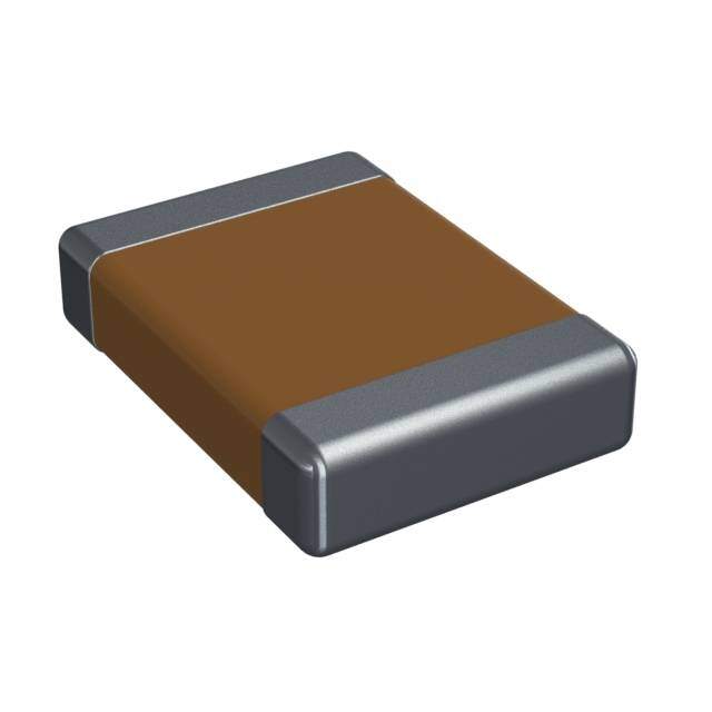
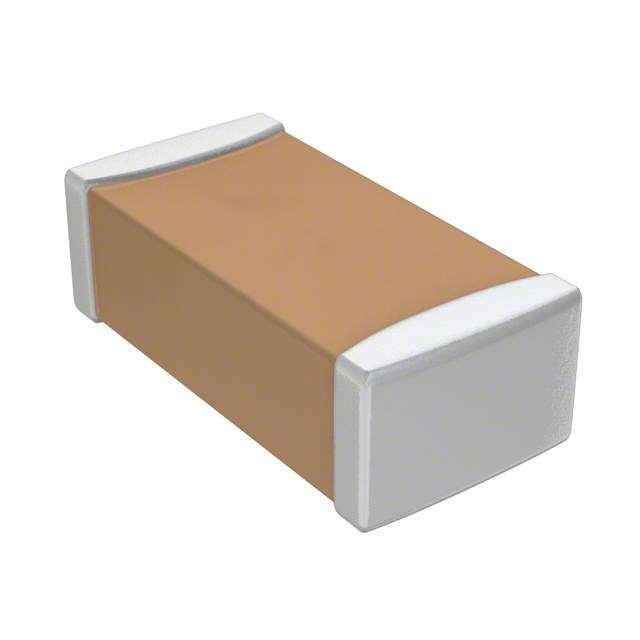
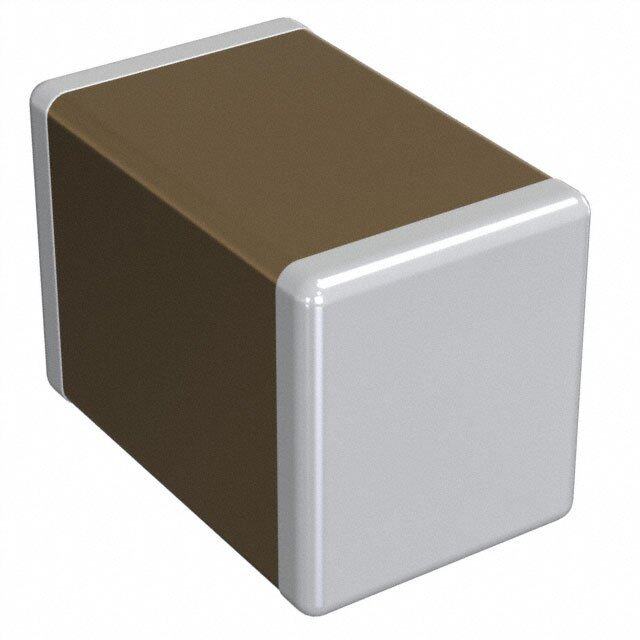
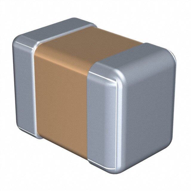
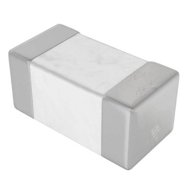
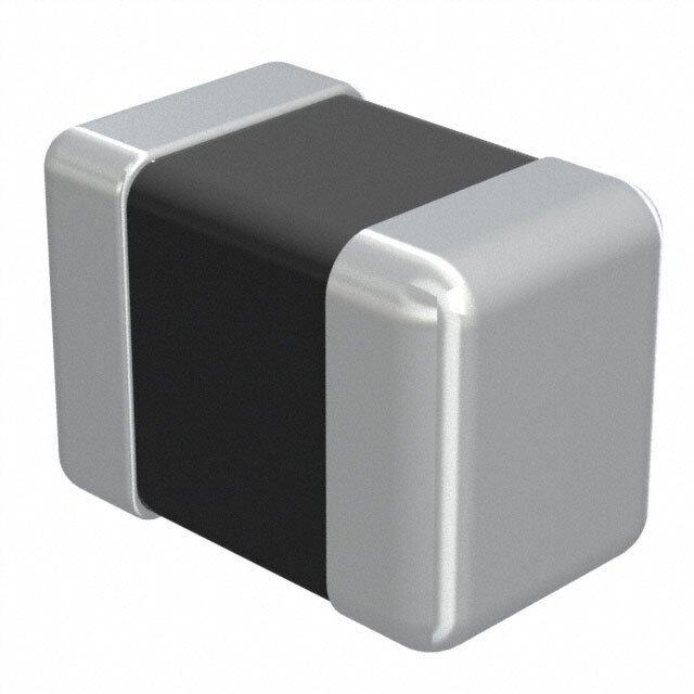
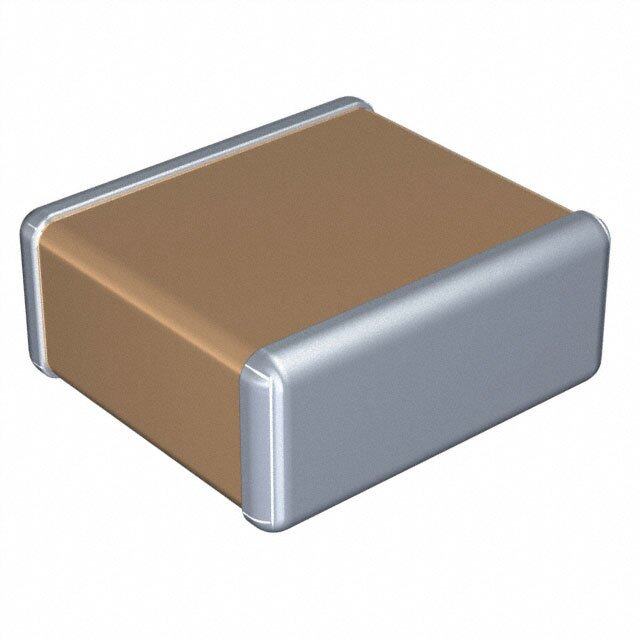
ICGOO电子元器件商城为您提供18125C104KAZ2A由AVX设计生产,在icgoo商城现货销售,并且可以通过原厂、代理商等渠道进行代购。 18125C104KAZ2A价格参考¥2.36-¥6.61。AVX18125C104KAZ2A封装/规格:陶瓷电容器, 0.1µF ±10% 50V Ceramic Capacitor X7R 1812 (4532 Metric)。您可以下载18125C104KAZ2A参考资料、Datasheet数据手册功能说明书,资料中有18125C104KAZ2A 详细功能的应用电路图电压和使用方法及教程。
AVX Corporation的18125C104KAZ2A是一款1812封装尺寸(英制:18×12密尔)的多层陶瓷电容器(MLCC),电容值为0.1μF(104表示10×10⁴pF),额定电压50V,精度±10%(K级),Z5U温度特性。该型号适用于对成本敏感且工作温度范围较宽但稳定性要求不极端的应用场景。

典型应用场景包括:
1. 电源去耦与旁路:广泛用于各类电子设备的集成电路供电引脚,滤除高频噪声,稳定电源电压,提升系统抗干扰能力。
2. 消费类电子产品:如电视、机顶盒、音响设备和家用电器中的信号耦合与滤波电路。
3. 工业控制设备:在PLC、传感器模块和电源管理单元中用于噪声抑制和信号平滑。
4. 照明系统:应用于LED驱动电源中的滤波环节,改善电流稳定性。
5. 汽车电子辅助系统:适用于非发动机舱内的车载电子模块,如信息娱乐系统或车内照明控制,因Z5U材料温度特性较宽(+10℃至+85℃),但在极端温差环境下稳定性有限,故不推荐用于高可靠性汽车主控系统。

该电容器具有体积小、成本低、高频响应好等优点,适合一般工业与民用电子设计。但由于其电容值随温度和电压变化较大,不适合精密定时或高稳定性滤波场合。总体而言,18125C104KAZ2A是一款通用型陶瓷电容,适用于中等环境条件下的去耦、滤波和耦合应用。
| 参数 | 数值 |
| 产品目录 | |
| 描述 | CAP CER 0.1UF 50V 10% X7R 1812多层陶瓷电容器MLCC - SMD/SMT 50v .1uF 10% FLEXITERM |
| 产品分类 | |
| 品牌 | AVX |
| 产品手册 | |
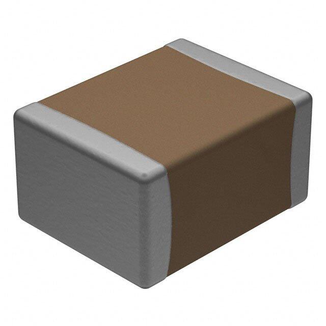
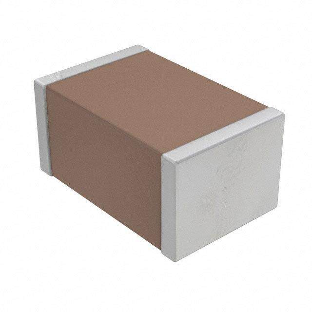
| 产品图片 |
|
| rohs | 符合RoHS无铅 / 符合限制有害物质指令(RoHS)规范要求 |
| 产品系列 | MLCC,多层陶瓷电容器MLCC - SMD/SMT,AVX 18125C104KAZ2AFLEXITERM® |
| 数据手册 | |
| 产品型号 | 18125C104KAZ2A |
| 产品 | General Type MLCCs |
| 产品培训模块 | http://www.digikey.cn/PTM/IndividualPTM.page?site=cn&lang=zhs&ptm=22024 |
| 产品种类 | 多层陶瓷电容器MLCC - SMD/SMT |
| 其它名称 | 18125C104KAZ2A/1K |
| 包装 | 带卷 (TR) |
| 厚度(最大值) | 0.040"(1.02mm) |
| 商标 | AVX |
| 商标名 | FLEXITERM |
| 外壳代码-in | 1812 |
| 外壳代码-mm | 4532 |
| 外壳宽度 | 3.2 mm |
| 外壳长度 | 4.5 mm |
| 外壳高度 | 2.54 mm |
| 大小/尺寸 | 0.177" 长 x 0.126" 宽(4.50mm x 3.20mm) |
| 安装类型 | 表面贴装,MLCC |
| 容差 | 10 % |
| 封装 | Reel |
| 封装/外壳 | 1812(4532 公制) |
| 封装/箱体 | 1812 (4532 metric) |
| 工作温度 | -55°C ~ 125°C |
| 工作温度范围 | - 55 C to + 125 C |
| 工厂包装数量 | 1000 |
| 应用 | Boardflex 敏感 |
| 引线形式 | - |
| 引线间距 | - |
| 标准包装 | 1,000 |
| 温度系数 | X7R |
| 温度系数/代码 | X7R |
| 特性 | 软端子 |
| 电介质 | X7R |
| 电压-额定 | 50V |
| 电压额定值 | 50 V |
| 电容 | 0.1µF |
| 端接类型 | SMD/SMT |
| 等级 | - |
| 类型 | X7R Flexiterm |
| 高度-安装(最大值) | - |


- 商务部:美国ITC正式对集成电路等产品启动337调查
- 曝三星4nm工艺存在良率问题 高通将骁龙8 Gen1或转产台积电
- 太阳诱电将投资9.5亿元在常州建新厂生产MLCC 预计2023年完工
- 英特尔发布欧洲新工厂建设计划 深化IDM 2.0 战略
- 台积电先进制程称霸业界 有大客户加持明年业绩稳了
- 达到5530亿美元!SIA预计今年全球半导体销售额将创下新高
- 英特尔拟将自动驾驶子公司Mobileye上市 估值或超500亿美元
- 三星加码芯片和SET,合并消费电子和移动部门,撤换高东真等 CEO
- 三星电子宣布重大人事变动 还合并消费电子和移动部门
- 海关总署:前11个月进口集成电路产品价值2.52万亿元 增长14.8%


PDF Datasheet 数据手册内容提取
MLCC with FLEXITERM® General Specifications GENERAL DESCRIPTION With increased requirements from the automotive industry for additional component robustness, AVX recognized the need to produce a MLCC with enhanced mechanical strength. It was noted that many components may be subject to severe flexing and vibration when used in various under the hood automotive and other harsh environment applications. To satisfy the requirement for enhanced mechanical strength, AVX had to find a way of ensuring electrical integrity is maintained whilst external forces are being applied to the component. It was found that the structure of the termination needed to be flexible and after much research and development, AVX launched FLEXITERM®. FLEXITERM® is designed to enhance the mechanical flexure and temperature cycling performance of a standard ceramic capacitor with an X7R dielectric. The industry standard for flexure is 2mm minimum. Using FLEXITERM®, AVX provides up to 5mm of flexure without internal cracks. Beyond 5mm, the capacitor will generally fail “open”. As well as for automotive applications FLEXITERM® will provide Design Engineers with a satisfactory solution when designing PCB’s which may be subject to high levels of board flexure. PRODUCT ADVANTAGES APPLICATIONS • High mechanical performance able to withstand, 5mm bend test guaranteed. High Flexure Stress Circuit Boards • Increased temperature cycling performance, 3000 cycles and beyond. • e.g. Depanelization: Components near edges of • Flexible termination system. board. • Reduction in circuit board flex failures. • Base metal electrode system. Variable Temperature Applications • Automotive or commercial grade products available. • Soft termination offers improved reliability performance in applications where there is temperature variation. • e.g. All kind of engine sensors: Direct connection to battery rail. Automotive Applications • Improved reliability. • Excellent mechanical performance and thermo mechanical performance. HOW TO ORDER 0805 5 C 104 K A Z 2 A Style Voltage Dielectric Capacitance Capacitance Failure Terminations Packaging Special Code 0603 6 = 6.3V C = X7R Code (In pF) Tolerance Rate Z = FLEXITERM® 2 = 7" Reel A = Std.Product 0805 Z = 10V F = X8R 2 Sig Digits + J = ±5%* A=Commercial For FLEXITERM® 4 = 13" Reel 1206 Y = 16V Number of Zeros K = ±10% 4 = Automotive with Tin/Lead 1210 3 = 25V e.g., 104 = 100nF M = ±20% termination see 1812 2220 5 = 50V AVX LD Series 1 = 100V *≤1μF only 2 = 200V NOTE: Contact factory for availability of Tolerance Options for Specific Part Numbers. The Important Information/Disclaimer is incorporated in these specifications 62 by reference and should be reviewed in full before placing any order. 020117
MLCC with FLEXITERM® Specifications and Test Methods PERFORMANCE TESTING BOARD BEND TEST PROCEDURE According to AEC-Q200 AEC-Q200 Qualification: Test Procedure as per AEC-Q200: • Created by the Automotive Electronics Sample size: 20 components Council Span: 90mm Minimum deflection spec: 2 mm • Specification defining stress LKONAIFDEING test qualification for passive • Components soldered onto FR4 PCB (Figure 1) components • Board connected electrically to the test equipment MASOSUENMTBINLYG Testing: (Figure 2) DIGITAL Key tests used to compare CALIPER soft termination to AEC-Q200 BEND TESTPLATE qualification: CONNECTOR • Bend Test CONTROL • Temperature Cycle Test PANEL CONTROL PANEL Fig 2 - Board Bend test Fig 1 - PCB layout with electrical connections equipment BOARD BEND TEST RESULTS AEC-Q200 Vrs AVX FLEXITERM® Bend Test m)12 0603 m)12 0805 AVX ENHANCED SOFT Substrate Bend (m1086420 Substrate Bend (m1086420 BTPeERnROd MCTeEIsNDtAUTRIEON BEND TEST NPO X7R X7R soft term NPO X7R X7R soft term The capacitor is soldered to the printed circuit board as shown and is bent up to 10mm at 1mm per 1210 Substrate Bend (mm)112086420 NPO 12X076R X7R soft term Substrate Bend (mm)112086420 NPO X7R X7R soft term second: Max. = 10mm TABLE SUMMARY 90mm Typical bend test results are shown below: Style Conventional Termination FLEXITERM® 0603 >2mm >5mm • The board is placed on 2 supports 90mm apart 0805 >2mm >5mm (capacitor side down) • The row of capacitors is aligned with the load 1206 >2mm >5mm stressing knife TEMPERATURE CYCLE TEST PROCEDURE Test Procedure as per AEC-Q200: The test is conducted to determine the resistance of the component Max. = 10mm when it is exposed to extremes of alternating high and low temperatures. • Sample lot size quantity 77 pieces • TC chamber cycle from -55ºC to +125ºC for 1000 cycles • Interim electrical measurements at 250, 500, 1000 cycles • Measure parameter capacitance dissipation factor, insulation resistance • The load is applied and the deflection where the part starts to crack is recorded (Note: Equipment detects the start of the crack using a highly sensitive current detection circuit) Test Temperature Profile (1 cycle) • The maximum deflection capability is 10mm The Important Information/Disclaimer is incorporated in these specifications by reference and should be reviewed in full before placing any order. 63 020117
MLCC with FLEXITERM® Specifications and Test Methods BEYOND 1000 CYCLES: TEMPERATURE CYCLE TEST RESULTS 0603 0805 10 10 8 8 e e ur 6 ur 6 ail ail F 4 F 4 % % 2 2 0 0 0 500 1000 1500 2000 2500 3000 0 500 1000 1500 2000 2500 3000 1206 1210 10 10 8 8 e e ur 6 ur 6 ail ail F 4 F 4 % % 2 2 0 0 0 500 1000 1500 2000 2500 3000 0 500 1000 1500 2000 2500 3000 AEC-Q200 specification states Soft Term - No Defects up to 3000 cycles 1000 cycles compared to AVX 3000 temperature cycles. FLEXITERM® TEST SUMMARY • Qualified to AEC-Q200 test/specification with the exception of • Board bend test improvement by a factor of 2 to 4 times. using AVX 3000 temperature cycles (up to +150°C bend test • Temperature Cycling: guaranteed greater than 5mm). – 0% Failure up to 3000 cycles • FLEXITERM® provides improved performance compared to – No ESR change up to 3000 cycle standard termination systems. WITHOUT SOFT TERMINATION WITH SOFT TERMINATION Major fear is of latent board flex failures. Far superior mechanical performance. Generally open failure mode beyond 5mm flexure The Important Information/Disclaimer is incorporated in these specifications 64 by reference and should be reviewed in full before placing any order. 020717
MLCC with FLEXITERM® Capacitance Range X8R Dielectric SIZE 0603 0805 1206 Soldering Reflow/Wave Reflow/Wave Reflow/Wave WVDC 25V 50V 25V 50V 25V 50V 271 Cap 270 G G 331 (pF) 330 G G J J 471 470 G G J J 681 680 G G J J 102 1000 G G J J J J 152 1500 G G J J J J 182 1800 G G J J J J 222 2200 G G J J J J 272 2700 G G J J J J 332 3300 G G J J J J 392 3900 G G J J J J 472 4700 G G J J J J 562 5600 G G J J J J 682 6800 G G J J J J 822 8200 G G J J J J 103 Cap 0.01 G G J J J J 123 (μF) 0.012 G G J J J J 153 0.015 G G J J J J 183 0.018 G G J J J J 223 0.022 G G J J J J 273 0.027 G G J J J J 333 0.033 G G J J J J 393 0.039 G G J J J J 473 0.047 G G J J J J 563 0.056 G N N M M 683 0.068 G N N M M 823 0.082 N N M M 104 0.1 N N M M 124 0.12 N N M M 154 0.15 N N M M 184 0.18 N M M 224 0.22 N M M 274 0.27 M M 334 0.33 M M 394 0.39 M 474 0.47 M 684 0.68 824 0.82 105 1 WVDC 25V 50V 25V 50V 25V 50V SIZE 0603 0805 1206 Letter A C E G J K M N P Q X Y Z Max. 0.33 0.56 0.71 0.90 0.94 1.02 1.27 1.40 1.52 1.78 2.29 2.54 2.79 Thickness (0.013) (0.022) (0.028) (0.035) (0.037) (0.040) (0.050) (0.055) (0.060) (0.070) (0.090) (0.100) (0.110) PAPER EMBOSSED TS 16949, ISO 9001Certified The Important Information/Disclaimer is incorporated in these specifications by reference and should be reviewed in full before placing any order. 65 020117
MLCC with FLEXITERM® Capacitance Range X7R Dielectric Size 0402 0603 0805 1206 1210 1812 2220 Reflow/ Reflow Soldering Reflow/Wave Reflow/Wave Reflow/Wave Reflow Only Reflow Only Wave Only WVDC 16V25V50V10V16V25V50V100 V200V 250V 16V 25V 50V100 V200V250V 16V 25V50V100 V200V250V500V 16V 25V 50V100 V 50V 100 V25V 50V 100 V 221 Cap 220 C C C 271 (pF) 270 C C C 331 330 C C C 391 390 C C C 471 470 C C C 561 560 C C C 681 680 C C C 821 820 C C C 102 1000 C C C G G G G G G J J J J J J J J J J J J J K K K K K K 182 1800 C C C G G G G G G J J J J J J J J J J J J J K K K K K K 222 2200 C C C G G G G G G J J J J J J J J J J J J J K K K K K K 332 3300 C C C G G G G G G J J J J J J J J J J J J J K K K K K K 472 4700 C C C G G G G G G J J J J J J J J J J J J J K K K K K K 103 Cap 0.01 C G G G G G G J J J J J J J J J J J J J K K K K K K 123 (μF) 0.012 C G G G J J J M J J J J J J J J K K K K K K 153 0.015 C G G G J J J M J J J J J J J J K K K K K K 183 0.018 C G G G J J J M J J J J J J J J K K K K K K 223 0.022 C G G G J J J J J J J J J J J J K K K K K K 273 0.027 C G G G J J J M J J J J J J J J K K K K K K 333 0.033 C G G G J J J M J J J J J J J J K K K K K K 473 0.047 G G G J J J M J J J J J M J J K K K K K K 563 0.056 G G G J J J M J J J M J J K K K M K K 683 0.068 G G G J J J M J J J M J J K K K M K K 823 0.082 G G G J J J M J J J M J J K K K M K K 104 0.1 C G G G J J M M J J J M J J K K K M K K 124 0.12 J J M N J J M M K K K P K K 154 0.15 M N M N J J M M K K K P K K 224 0.22 G M N M N J M M Q M M M P M M 334 0.33 N N M N J M P Q P P P Q X X 474 0.47 N N M N M M P Q P P P Q X X 684 0.68 N N N M Q Q Q P P Q X X X 105 1 N N N M Q Q Q P Q Q Z X X 155 1.5 Q Q Q P Q Z Z X X 225 2.2 Q Q Q X Z Z Z Z Z 335 3.3 Q Q X Z Z Z Z 475 4.7 Q Q X Z Z Z Z Z 106 10 Z Z Z Z 226 22 Z WVDC 16V25V50V10V16V25V50V100 V200V 250V 16V 25V 50V100 V200V250V 16V 25V50V100 V200V250V500V 16V 25V 50V100 V 50V 100 V25V 50V 100 V Size 0402 0603 0805 1206 1210 1812 2220 Letter A C E G J K M N P Q X Y Z Max. 0.33 0.56 0.71 0.90 0.94 1.02 1.27 1.40 1.52 1.78 2.29 2.54 2.79 Thickness (0.013) (0.022) (0.028) (0.035) (0.037) (0.040) (0.050) (0.055) (0.060) (0.070) (0.090) (0.100) (0.110) PAPER EMBOSSED The Important Information/Disclaimer is incorporated in these specifications 66 by reference and should be reviewed in full before placing any order. 021820
IMPORTANT INFORMATION/DISCLAIMER All product specifications, statements, information and data (collectively, the “Information”) in this datasheet or made available on the website are subject to change. The customer is responsible for checking and verifying the extent to which the Information contained in this publication is applicable to an order at the time the order is placed. All Information given herein is believed to be accurate and reliable, but it is presented without guarantee, warranty, or responsibility of any kind, expressed or implied. Statements of suitability for certain applications are based on AVX’s knowledge of typical operating conditions for such applications, but are not intended to constitute and AVX specifically disclaims any warranty concerning suitability for a specific customer application or use. ANY USE OF PRODUCT OUTSIDE OF SPECIFICATIONS OR ANY STORAGE OR INSTALLATION INCONSISTENT WITH PRODUCT GUIDANCE VOIDS ANY WARRANTY. The Information is intended for use only by customers who have the requisite experience and capability to determine the correct products for their application. Any technical advice inferred from this Information or otherwise provided by AVX with reference to the use of AVX’s products is given without regard, and AVX assumes no obligation or liability for the advice given or results obtained. Although AVX designs and manufactures its products to the most stringent quality and safety standards, given the current state of the art, isolated component failures may still occur. Accordingly, customer applications which require a high degree of reliability or safety should employ suitable designs or other safeguards (such as installation of protective circuitry or redundancies) in order to ensure that the failure of an electrical component does not result in a risk of personal injury or property damage. Unless specifically agreed to in writing, AVX has not tested or certified its products, services or deliverables for use in high risk applications including medical life support, medical device, direct physical patient contact, water treatment, nuclear facilities, weapon systems, mass and air transportation control, flammable environments, or any other potentially life critical uses. Customer understands and agrees that AVX makes no assurances that the products, services or deliverables are suitable for any high-risk uses. Under no circumstances does AVX warrant or guarantee suitability for any customer design or manufacturing process. Although all product–related warnings, cautions and notes must be observed, the customer should not assume that all safety measures are indicted or that other measures may not be required. The Important Information/Disclaimer is incorporated in these specifications by reference and should be reviewed in full before placing any order. 121119