ICGOO在线商城 > 138D187X9025F2

 Datasheet下载
- 型号: 138D187X9025F2
- 制造商: Vishay
- 库位|库存: xxxx|xxxx
- 要求:
| 数量阶梯 | 香港交货 | 国内含税 |
| +xxxx | $xxxx | ¥xxxx |
查看当月历史价格
查看今年历史价格
138D187X9025F2产品简介:
ICGOO电子元器件商城为您提供138D187X9025F2由Vishay设计生产,在icgoo商城现货销售,并且可以通过原厂、代理商等渠道进行代购。 提供138D187X9025F2价格参考以及Vishay138D187X9025F2封装/规格参数等产品信息。 你可以下载138D187X9025F2参考资料、Datasheet数据手册功能说明书, 资料中有138D187X9025F2详细功能的应用电路图电压和使用方法及教程。
| 参数 | 数值 |
| ESR | 4 Ohms |
| 品牌 | Vishay |
| 产品目录 | 无源元件 |
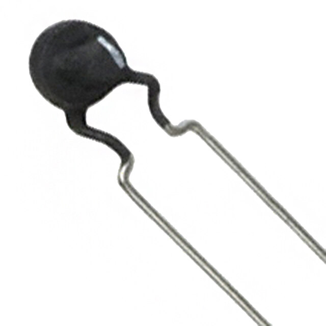
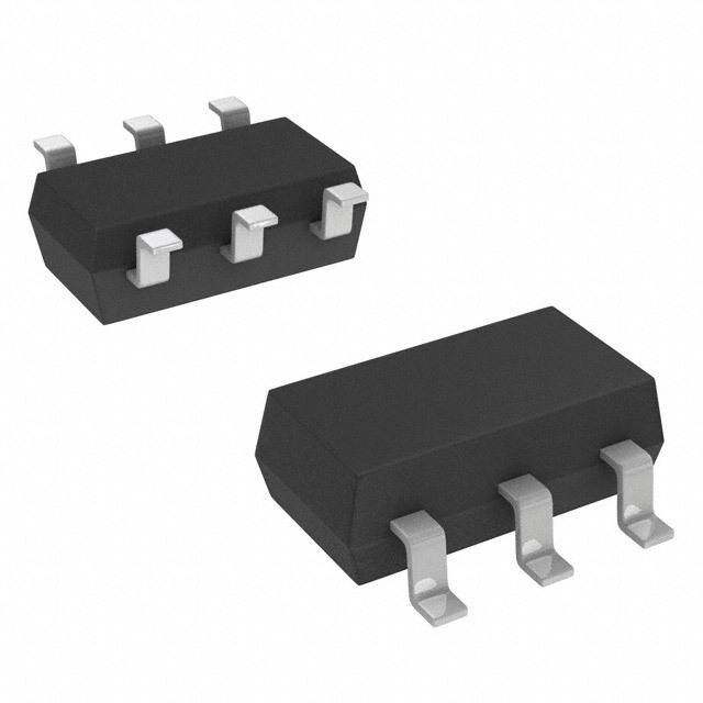
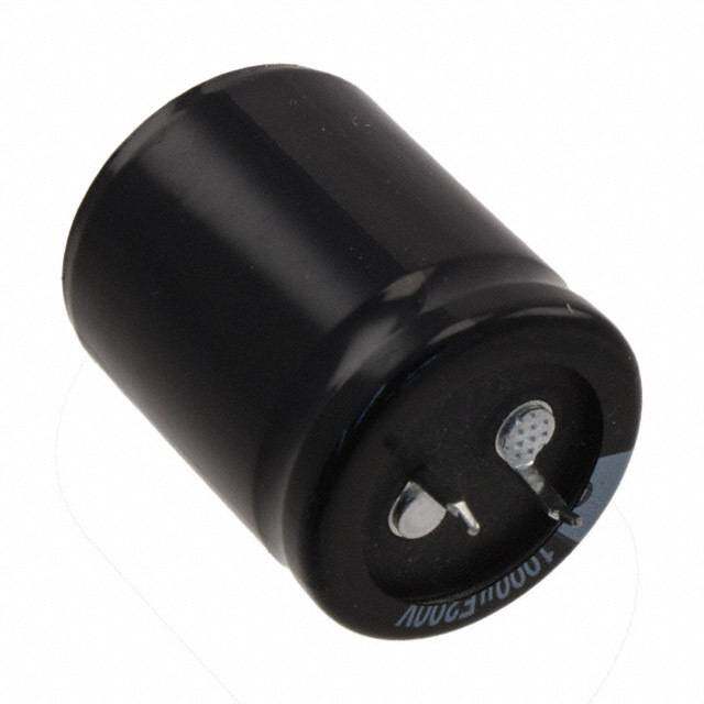
| 描述 | 钽质电容器-湿式 25volts 180uF 10% F Case |
| 产品分类 | |
| 产品手册 | |
| 产品图片 |
|
| rohs | 否 |
| 产品系列 | 钽电容器,钽质电容器-湿式,Vishay 138D187X9025F2 |
| 产品型号 | 138D187X9025F2 |
| 产品 | Tantalum Wet Hermetically Sealed |
| 产品种类 | 钽质电容器-湿式 |
| 制造商库存号 | F Case |
| 商标 | Vishay |
| 外壳直径 | 7.92 mm |
| 外壳长度 | 20.22 mm |
| 容差 | 10 % |
| 工作温度范围 | - 55 C to + 85 C |
| 漏泄电流 | 3 uA |
| 电压额定值 | 25 V |
| 电容 | 180 uF |
| 端接类型 | Axial |
| 系列 | 138D |


- 商务部:美国ITC正式对集成电路等产品启动337调查
- 曝三星4nm工艺存在良率问题 高通将骁龙8 Gen1或转产台积电
- 太阳诱电将投资9.5亿元在常州建新厂生产MLCC 预计2023年完工
- 英特尔发布欧洲新工厂建设计划 深化IDM 2.0 战略
- 台积电先进制程称霸业界 有大客户加持明年业绩稳了
- 达到5530亿美元!SIA预计今年全球半导体销售额将创下新高
- 英特尔拟将自动驾驶子公司Mobileye上市 估值或超500亿美元
- 三星加码芯片和SET,合并消费电子和移动部门,撤换高东真等 CEO
- 三星电子宣布重大人事变动 还合并消费电子和移动部门
- 海关总署:前11个月进口集成电路产品价值2.52万亿元 增长14.8%


PDF Datasheet 数据手册内容提取
138D www.vishay.com Vishay Wet Tantalum Capacitors Silver Case TANTALEX™ Capacitors Hermetically-Sealed FEATURES • Terminations: axial, standard tin / lead (SnPb) , 100 % tin (RoHS-compliant) available Available • Model 138D is the commercial equivalents o f Tansitor styles WT, UWT, Mallory-NACC style s Available TLX, TXX and military styles CL66, CL67 , CLR65, and CLR69, designed to meet the performance requirements of military specification MIL-PRF-39006/9/21. Available Capacitors in accordance with military specification s should be ordered by their military part numbers • Material categorization: for definitions of complianc e please see www.vishay.com/doc?99912 Note * This datasheet provides information about parts that are RoHS-compliant and / or parts that are non RoHS-compliant. For example, parts with lead (Pb) terminations are not RoHS-compliant. Please see the information / tables in this datasheet for details PERFORMANCE CHARACTERISTICS Operating Temperature: -55 °C to +85 °C Following the life test: (to +125 °C with voltage derating) 1.DCL shall not exceed 125 % of the original requirement. Capacitance Tolerance: at 120 Hz, +25 °C. ± 20 % 2.The ESR shall not exceed 200 % of the initial standard. ± 10 %, ± 5 % available as special. requirement. DC Leakage Current (DCL Max.): at +25 °C, +85 °C and 3.Change in capacitance value shall not exceed the +125 °C: leakage current shall not exceed the values liste d percentages below. in the Standard Ratings tables. a) 6 V units: +10 % to -25 % of initial measurement. DC Life Test: capacitors are capable of withstanding a 2000 h b) 8 V and 10 V units: +10 % to -20 % of initial DC DC life test at a temperature of +85 °C or +125 °C at the measurement. applicable rated DC working voltage. c) 15 V units: +10 % to -15 % of initial measurement. DC d) 20 V and above: ± 10 % of initial measurement. DC ORDERING INFORMATION 138D 306 X0 006 C 2 E3 MODEL CAPACITANCE CAPACITANCE DC VOLTAGE RATING CASE STYLE NUMBER RoHS-COMPLIANT TOLERANCE AT +85 °C CODE This is expressed X0 = ± 20 % This is expressed in volts. See 0 = no outer sleeve E3 = 100 % tin in picofarads. The X9 = ± 10 % To complete the Ratings 2 = outer plastic termination first two digits are X5 = ± 5 % three-digit block, zeros and Case film insulation (RoHS-compliant) the significant special order precede the voltage Codes 6 = high temperature Blank = SnPb figures. The third is rating. A decimal point is table film insulation termination the number of indicated by an “R” (standard design) zeros to follow (6R3 = 6.3 V) Note • Packaging: the use of formed plastic trays for packaging these axial lead components is standard. Tape and reel is not available due to th e unit weight Revision: 07-Mar-2019 1 Document Number: 40025 For technical questions, contact: tantalum@vishay.com THIS DOCUMENT IS SUBJECT TO CHANGE WITHOUT NOTICE. THE PRODUCTS DESCRIBED HEREIN AND THIS DOCUMENT ARE SUBJECT TO SPECIFIC DISCLAIMERS, SET FORTH AT www.vishay.com/doc?91000
138D www.vishay.com Vishay DIMENSIONS in inches [millimeters] 0.250 [6.35] L D Max. 0.0253 ± 0.002 [0.64 ± 0.05] dia. Weld (no. 22 AWG) t inned solderable leads Tantalum CASE BARE TUBE WITFHIL MOU INTESRU LPALTAISOTNIC - LEAD LENGTH WMEIAGXH. T CODE D L D (MAX.) L (1) (oz. / g) 0.188 ± 0.016 0.453 + 0.031 / - 0.016 0.219 0.595 1.500 ± 0.250 0.07 C [4.78 ± 0.41] [11.51 + 0.79 / - 0.41] [5.56] [15.11] [38.10 ± 6.35] [2.0] 0.281 ± 0.016 0.641 + 0.031 / - 0.016 0.312 0.785 2.250 ± 0.250 0.18 F [7.14 ± 0.41] [16.28 + 0.79 / - 0.41] [7.92] [19.94] [57.15 ± 6.35] [5.1] 0.375 ± 0.016 0.766 + 0.031 / - 0.016 0.406 0.92 2.250 ± 0.250 0.36 T [9.53 ± 0.41] [19.46 + 0.79 / - 0.41] [10.31] [23.37] [57.15 ± 6.35] [10.2] 0.375 ± 0.016 1.062 + 0.031 / - 0.023 0.406 1.225 2.250 ± 0.250 0.49 K [9.53 ± 0.41] [26.97 + 0.79 / - 0.58] [10.31] [31.11] [57.15 ± 6.35] [13.9] Note (1) Typical length, for reference only STANDARD RATINGS MAX. DCL (μA) MAX. CAPACITANCE MAX. RMS MAX. ESR MAX. IMP. AT CHANGE (%) AT RIPPLE CAPACITANCE CASE AT +25 °C AT -55 °C PART NUMBER (1) CURRENT (μF) CODE 12(0 H) z 12(0 H) z +25 °C ++18255 ° °CC -55 °C +85 °C +125 °C 1(2m0 AH)z 6 V AT +85 °C; 4 V AT +125 °C DC DC 30 C 138D306X0006C2 4 100 1 2 -40 +10.5 +12 140 68 C 138D686X0006C2 4 60 1 2 -40 +14 +16 160 140 F 138D147X0006F2 2 40 1 3 -40 +14 +16 330 270 F 138D277X0006F2 4 25 1 6.5 -44 +17.5 +20 330 330 T 138D337X0006T2 2 20 2 7.9 -44 +14 +16 410 560 T 138D567X0006T2 3 25 2 13 -64 +17.5 +20 410 1200 K 138D128X0006K2 1.6 20 3 14 -80 +25 +25 530 8 V AT +85 °C; 5 V AT +125 °C DC DC 25 C 138D256X0008C2 4 100 1 2 -40 +10.5 +12 140 56 C 138D566X0008C2 4 59 1 2 -40 +14 +16 160 220 F 138D227X0008F2 4 30 1 7 -44 +17.5 +20 270 430 T 138D437X0008T2 3 25 2 14 -64 +17.5 +20 410 850 K 138D857X0008K2 1 22 4 16 -80 +25 +25 670 10 V AT +85 °C; 7 V AT +125 °C DC DC 20 C 138D206X0010C2 4 175 1 2 -32 +10.5 +12 140 47 C 138D476X0010C2 5 100 1 2 -36 +14 +16 160 100 F 138D107X0010F2 2 60 1 4 -36 +14 +16 270 180 F 138D187X0010F2 4 40 1 7 -36 +14 +16 270 250 T 138D257X0010T2 2 30 2 10 -40 +14 +16 410 390 T 138D397X0010T2 3 25 2 16 -64 +17.5 +20 410 750 K 138D757X0010K2 1 23 4 16 -80 +25 +25 670 Note (1) Part numbers listed are for units with ± 20 % capacitance tolerance insulated capacitors. For ± 10 % tolerance capacitors, change the digi t following the letter “X” from “0” to “9”; for ± 5 %, change the digit following the letter “X” from “0” to “5”. For capacitors without outer polyester-film insulation, change the last digit in the part number from “2” to “0”. For capacitors with a high temperature insulating sleeve , change the last digit in the part number from “2” to “6”. For RoHS-compliant add “E3” Revision: 07-Mar-2019 2 Document Number: 40025 For technical questions, contact: tantalum@vishay.com THIS DOCUMENT IS SUBJECT TO CHANGE WITHOUT NOTICE. THE PRODUCTS DESCRIBED HEREIN AND THIS DOCUMENT ARE SUBJECT TO SPECIFIC DISCLAIMERS, SET FORTH AT www.vishay.com/doc?91000
138D www.vishay.com Vishay STANDARD RATINGS MAX. DCL (μA) MAX. CAPACITANCE MAX. RMS MAX. ESR MAX. IMP. AT CHANGE (%) AT RIPPLE CAPACITANCE CASE AT +25 °C AT -55 °C PART NUMBER (1) CURRENT (μF) CODE 12(0 H) z 12(0 H) z +25 °C ++18255 ° °CC -55 °C +85 °C +125 °C 1(2m0 AH)z 15 V AT +85 °C; 10 V AT +125 °C DC DC 15 C 138D156X0015C2 5 155 1 2 -24 +10.5 +12 130 33 C 138D336X0015C2 5 90 1 2 -28 +14 +16 160 70 F 138D706X0015F2 4 75 1 4 -28 +14 +16 270 120 F 138D127X0015F2 4 50 1 7 -28 +17.5 +20 270 170 T 138D177X0015T2 2 35 2 10 -32 +14 +16 410 270 T 138D277X0015T2 3 30 2 16 -56 +17.5 +20 410 540 K 138D547X0015K2 1.0 23 6 24 -80 +25 +25 610 20 V AT +85 °C; 13 V AT +125 °C DC DC 27 C 138D276X0020C2 5 100 1 2 -20 +11 +14 160 220 T 138D227X0020T2 4 30 2 16 -48 +13 +15 410 25 V AT +85 °C; 15 V AT +125 °C DC DC 10 C 138D106X0025C2 6 220 1 2 -16 +8 +9 130 22 C 138D226X0025C2 5 140 1 2 -20 +10.5 +12 160 27 C 138D276X0025C2 4.3 110 2 9 -35 +12 +15 160 50 F 138D506X0025F2 4 70 1 5 -28 +13 +15 270 100 F 138D107X0025F2 4 50 1 10 -28 +13 +15 270 180 T 138D187X0025T2 4 32 2 18 -48 +13 +15 340 350 K 138D357X0025K2 1.3 24 7 28 -70 +25 +25 580 30 V AT +85 °C; 20 V AT +125 °C DC DC 8.0 C 138D805X0030C2 7.5 275 1 2 -16 +8 +12 130 15 C 138D156X0030C2 8 175 1 2 -20 +10.5 +12 160 40 F 138D406X0030F2 4 65 1 5 -24 +10.5 +12 270 100 T 138D107X0030T2 6 40 2 12 -28 +10.5 +12 410 150 T 138D157X0030T2 2.5 35 2 16 -48 +13 +15 340 300 K 138D307X0030K2 1.6 25 8 32 -60 +25 +25 550 35 V AT +85 °C; 22 V AT +125 °C DC DC 68 F 138D686X0035F2 6 60 1 8 -24 +12 +15 270 27 C 138D276X0035C2 4 140 2 9 -28 +10 +12 140 120 T 138D127X0035T2 4 38 2 16 -30 +13 +15 410 270 K 138D277X0035K2 2.2 23 8 32 -45 +20 +25 500 50 V AT +85 °C; 30 V AT +125 °C DC DC 5.0 C 138D505X0050C2 9 400 1 2 -16 +5 +6 130 10 C 138D106X0050C2 8 250 1 2 -24 +8 +9 160 25 F 138D256X0050F2 6 95 1 5 -20 +10.5 +12 270 47 F 138D476X0050F2 6 70 1 9 -28 +10.5 +15 270 60 T 138D606X0050T2 3 45 2 12 -16 +10.5 +12 410 82 T 138D826X0050T2 4 45 2 16 -32 +13 +15 410 160 K 138D167X0050K2 2.2 27 8 32 -50 +25 +25 460 Note (1) Part numbers listed are for units with ± 20 % capacitance tolerance insulated capacitors. For ± 10 % tolerance capacitors, change the digi t following the letter “X” from “0” to “9”; for ± 5 %, change the digit following the letter “X” from “0” to “5”. For capacitors without outer polyester-film insulation, change the last digit in the part number from “2” to “0”. For capacitors with a high temperature insulating sleeve , change the last digit in the part number from “2” to “6”. For RoHS-compliant add “E3” Revision: 07-Mar-2019 3 Document Number: 40025 For technical questions, contact: tantalum@vishay.com THIS DOCUMENT IS SUBJECT TO CHANGE WITHOUT NOTICE. THE PRODUCTS DESCRIBED HEREIN AND THIS DOCUMENT ARE SUBJECT TO SPECIFIC DISCLAIMERS, SET FORTH AT www.vishay.com/doc?91000
138D www.vishay.com Vishay STANDARD RATINGS MAX. DCL (μA) MAX. CAPACITANCE MAX. RMS MAX. ESR MAX. IMP. AT CHANGE (%) AT RIPPLE CAPACITANCE CASE AT +25 °C AT -55 °C PART NUMBER (1) CURRENT (μF) CODE 12(0 H) z 12(0 H) z +25 °C ++18255 ° °CC -55 °C +85 °C +125 °C 1(2m0 AH)z 60 V AT +85 °C; 40 V AT +125 °C DC DC 4.0 C 138D405X0060C2 10 550 1 2 -16 +5 +6 110 8.2 C 138D825X0060C2 8 275 1 2 -24 +8 +9 140 20 F 138D206X0060F2 5 105 1 5 -16 +10.5 +12 270 39 F 138D396X0060F2 7 90 1 9 -28 +10.5 +12 330 50 T 138D506X0060T2 4 50 2 12 -16 +10.5 +12 410 68 T 138D686X0060T2 6 50 2 16 -32 +10.5 +12 410 140 K 138D147X0060K2 2.4 28 8 32 -40 +20 +20 430 75 V AT +85 °C; 50 V AT +125 °C DC DC 3.5 C 138D355X0075C2 10 650 1 2 -16 +5 +6 110 6.8 C 138D685X0075C2 8 300 1 2 -20 +8 +9 140 15 F 138D156X0075F2 6.5 150 1 5 -16 +8 +9 270 33 F 138D336X0075F2 7 90 1 10 -24 +10.5 +15 270 40 T 138D406X0075T2 5 60 2 12 -16 +10.5 +12 410 56 T 138D566X0075T2 6 60 2 17 -28 +10.5 +15 410 110 K 138D117X0075K2 3.1 29 9 36 -35 +20 +20 110 100 V AT +85 °C; 65 V AT +125 °C DC DC 2.5 C 138D255X0100C2 26.5 950 1 2 -16 +7 +8 100 4.7 C 138D475X0100C2 10 500 1 2 -16 +7 +8 130 11 F 138D116X0100F2 6 200 1 4 -16 +7 +8 230 22 F 138D226X0100F2 7 100 1 9 -16 +7 +8 230 30 T 138D306X0100T2 4 80 2 12 -16 +7 +8 340 43 T 138D436X0100T2 6 70 2 17 -20 +7 +8 340 86 K 138D866X0100K2 3.1 30 9 36 -25 +15 +15 400 125 V AT +85 °C; 85 V AT +125 °C DC DC 1.7 C 138D175X0125C2 54.6 1250 1 2 -16 +7 +8 100 3.6 C 138D365X0125C2 15 600 1 2 -16 +7 +8 110 9.0 F 138D905X0125F2 15 240 1 5 -16 +7 +8 210 14 F 138D146X0125F2 12 167 1 7 -16 +7 +8 210 18 T 138D186X0125T2 11 129 2 9 -16 +7 +8 340 25 T 138D256X0125T2 10 93 2 13 -16 +7 +8 340 56 K 138D566X0125K2 4.1 32 10 40 -25 +15 +15 400 Note (1) Part numbers listed are for units with ± 20 % capacitance tolerance insulated capacitors. For ± 10 % tolerance capacitors, change the digi t following the letter “X” from “0” to “9”; for ± 5 %, change the digit following the letter “X” from “0” to “5”. For capacitors without outer polyester-film insulation, change the last digit in the part number from “2” to “0”. For capacitors with a high temperature insulating sleeve , change the last digit in the part number from “2” to “6”. For RoHS-compliant add “E3” Revision: 07-Mar-2019 4 Document Number: 40025 For technical questions, contact: tantalum@vishay.com THIS DOCUMENT IS SUBJECT TO CHANGE WITHOUT NOTICE. THE PRODUCTS DESCRIBED HEREIN AND THIS DOCUMENT ARE SUBJECT TO SPECIFIC DISCLAIMERS, SET FORTH AT www.vishay.com/doc?91000
138D www.vishay.com Vishay EXTENDED RATINGS MAX. DCL (μA) MAX. CAPACITANCE CHANGE MAX. RMS MAX. ESR MAX. IMP. AT (%) AT RIPPLE CAPACITANCE CASE AT +25 °C AT -55 °C PART NUMBER (1) CURRENT (μF) CODE 12(0 H) z 12(0 H) z +25 °C ++18255 ° °CC -55 °C +85 °C +125 °C 1(2m0 AH)z 6 V AT +85 °C; 4 V AT +125 °C DC DC 560 F 138D567X0006F2 2.5 20 3 14 -80 +16 +20 300 820 F 138D827X0006F2 2.5 18 3 14 -88 +16 +20 300 1500 T 138D158X0006T2 1.5 18 5 20 -90 +20 +25 480 2200 K 138D228X0006K2 1 13 6 24 -90 +25 +30 670 8 V AT +85 °C; 5 V AT +125 °C DC DC 180 C 138D187X0008C2 3 45 2 9 -60 +13 +16 180 470 F 138D477X0008F2 2.5 25 3 14 -75 +16 +20 300 680 F 138D687X0008F2 2.5 22 3 14 -83 +16 +20 300 1800 K 138D188X0008K2 1 14 7 25 -90 +20 +30 670 10 V AT +85 °C; 7 V AT +125 °C DC DC 100 C 138D107X0010C2 3 60 2 9 -50 +13 +16 160 150 C 138D157X0010C2 3 54 2 9 -55 +13 +16 180 390 F 138D397X0010F2 2.5 30 3 16 -70 +16 +20 300 560 F 138D567X0010F2 2.5 27 3 16 -77 +16 +20 300 1200 T 138D128X0010T2 1.5 18 5 20 -88 +20 +25 480 1500 K 138D158X0010K2 1 15 7 25 -88 +25 +30 670 15 V AT +85 °C; 10 V AT +125 °C DC DC 68 C 138D686X0015C2 4 80 2 9 -40 +13 +16 140 100 C 138D107X0015C2 4 72 2 9 -44 +13 +16 160 270 F 138D277X0015F2 2.5 35 3 16 -60 +16 +20 300 390 F 138D397X0015F2 2.5 31 3 16 -16 +16 +20 300 540 T 138D547X0015T2 1.8 25 6 24 -70 +20 +25 440 820 T 138D827X0015T2 1.8 22 6 24 -77 +20 +25 440 1000 K 138D108X0015K2 1.2 17 8 32 -77 +25 +30 610 20 V AT +85 °C; 13 V AT +125 °C DC DC 56 C 138D566X0020C2 4.3 90 2 9 -38 +13 +16 140 82 C 138D826X0020C2 4.3 81 2 9 -43 +13 +16 160 220 F 138D227X0020F2 2.7 35 3 16 -60 +16 +20 300 330 F 138D337X0020F2 2.7 31 3 16 -66 +16 +20 300 25 V AT +85 °C; 15 V AT +125 °C DC DC 47 C 138D476X0025C2 4.3 100 2 9 -35 +12 +15 140 68 C 138D686X0025C2 4.3 90 2 9 -40 +12 +15 160 180 F 138D187X0025F2 2.7 37 3 16 -55 +13 +16 300 270 F 138D277X0025F2 2.7 33 3 16 -62 +13 +16 300 350 T 138D357X0025T2 1.8 27 7 28 -60 +20 +25 440 680 K 138D687X0025K2 1.2 19 8 32 -72 +25 +30 670 30 V AT +85 °C; 20 V AT +125 °C DC DC 39 C 138D396X0030C2 5.2 110 2 9 -32 +12 +15 140 56 C 138D566X0030C2 5.2 100 2 9 -38 +12 +15 140 150 F 138D157X0030F2 2.5 40 3 16 -50 +13 +16 300 220 F 138D227X0030F2 2.5 36 3 16 -60 +13 +16 300 300 T 138D307X0030T2 1.8 30 8 32 -60 +20 +25 500 330 T 138D337X0030T2 1.8 28 8 32 -50 +20 +25 440 470 T 138D477X0030T2 1.8 25 8 32 -65 +20 +25 440 560 K 138D567X0030K2 1.3 20 9 36 -65 +25 +30 590 Note (1) Part numbers listed are for units with ± 20 % capacitance tolerance insulated capacitors. For ± 10 % tolerance capacitors, change the digi t following the letter “X” from “0” to “9”; for ± 5 %, change the digit following the letter “X” from “0” to “5”. For capacitors without outer polyester-film insulation, change the last digit in the part number from “2” to “0”. For capacitors with a high temperature insulating sleeve , change the last digit in the part number from “2” to “6”. For RoHS-compliant add “E3” Revision: 07-Mar-2019 5 Document Number: 40025 For technical questions, contact: tantalum@vishay.com THIS DOCUMENT IS SUBJECT TO CHANGE WITHOUT NOTICE. THE PRODUCTS DESCRIBED HEREIN AND THIS DOCUMENT ARE SUBJECT TO SPECIFIC DISCLAIMERS, SET FORTH AT www.vishay.com/doc?91000
138D www.vishay.com Vishay EXTENDED RATINGS MAX. DCL (μA) MAX. CAPACITANCE CHANGE MAX. RMS MAX. ESR MAX. IMP. AT (%) AT RIPPLE CAPACITANCE CASE AT +25 °C AT -55 °C PART NUMBER (1) CURRENT (μF) CODE 12(0 H) z 12(0 H) z +25 °C ++18255 ° °CC -55 °C +85 °C +125 °C 1(2m0 AH)z 35 V AT +85 °C; 22 V AT +125 °C DC DC 33 C 138D336X0035C2 5.2 130 2 9 -30 +10 +12 140 47 C 138D476X0035C2 5.2 115 2 9 -35 +10 +12 140 100 T 138D107X0035T2 2.0 40 2 12 -28 +10.5 +12 410 120 F 138D127X0035F2 2.5 45 3 16 -45 +13 +16 300 220 T 138D227X0035T2 1.8 30 8 32 -45 +20 +25 440 390 T 138D397X0035T2 1.8 27 8 32 -58 +20 +25 440 470 K 138D477X0035K2 1.3 21 9 36 -58 +25 +30 590 50 V AT +85 °C; 30 V AT +125 °C DC DC 22 C 138D226X0050C2 5 150 2 9 -24 +10 +12 140 33 C 138D336X0050C2 5 135 2 9 -29 +10 +12 140 82 F 138D826X0050F2 2.5 55 4 24 -35 +10 +15 300 120 F 138D127X0050F2 2.5 49 4 24 -42 +12 +15 300 160 T 138D167X0050T2 1.8 32 6 32 -35 +20 +25 420 270 T 138D277X0050T2 1.8 29 8 32 -46 +20 +25 440 330 K 138D337X0050K2 1.5 22 9 36 -46 +25 +30 550 60 V AT +85 °C; 40 V AT +125 °C DC DC 18 C 138D186X0060C2 5 160 3 12 -20 +10 +12 140 27 C 138D276X0060C2 5 144 3 12 -24 +10 +12 140 68 F 138D686X0060F2 3 60 4 20 -30 +12 +15 270 100 F 138D107X0060F2 2.5 54 4 20 -36 +12 +15 300 140 T 138D147X0060T2 2 32 8 32 -30 +16 +20 420 220 T 138D227X0060T2 1.8 29 8 32 -40 +16 +20 440 270 K 138D277X0060K2 1.5 23 9 36 -45 +20 +25 550 75 V AT +85 °C; 50 V AT +125 °C DC DC 15 C 138D156X0075C2 5 175 3 12 -16 +10 +12 140 22 C 138D226X0075C2 5 157 3 12 -19 +10 +12 140 56 F 138D566X0075F2 3 70 4 24 -25 +12 +15 270 82 F 138D826X0075F2 2.5 63 4 24 -30 +12 +15 300 110 T 138D117X0075T2 2 33 9 36 -25 +16 +20 420 180 T 138D187X0075T2 1.8 30 9 36 -35 +16 +20 440 220 K 138D227X0075K2 2.2 24 10 40 -40 +20 +25 450 100 V AT +85 °C; 65 V AT +125 °C DC DC 3.9 C 138D395X0100C2 7 600 1 2 -16 +7 +8 130 8.2 C 138D825X0100C2 6 250 3 12 -12 +10 +12 130 10 C 138D106X0100C2 6 200 3 12 -17 +10 +12 130 33 F 138D336X0100F2 3.5 85 5 24 -18 +12 +15 250 39 F 138D396X0100F2 3.5 80 5 24 -20 +12 +15 250 68 T 138D686X0100T2 2.2 40 10 40 -30 +14 +16 400 120 K 138D127X0100K2 2.8 30 12 48 -35 +15 +17 440 125 V AT +85 °C; 85 V AT +125 °C DC DC 6.8 C 138D685X0125C2 11.7 300 3 12 -14 +10 +12 130 27 F 138D276X0125F2 3.5 90 5 24 -18 +12 +15 250 39 T 138D396X0125T2 2.2 60 10 40 -16 +14 +16 400 47 T 138D476X0125T2 2.2 50 10 40 -26 +14 +16 400 82 K 138D826X0125K2 2.8 32 12 48 -30 +15 +17 440 Note (1) Part numbers listed are for units with ± 20 % capacitance tolerance insulated capacitors. For ± 10 % tolerance capacitors, change the digi t following the letter “X” from “0” to “9”; for ± 5 %, change the digit following the letter “X” from “0” to “5”. For capacitors without outer polyester-film insulation, change the last digit in the part number from “2” to “0”. For capacitors with a high temperature insulating sleeve , change the last digit in the part number from “2” to “6”. For RoHS-compliant add “E3” Revision: 07-Mar-2019 6 Document Number: 40025 For technical questions, contact: tantalum@vishay.com THIS DOCUMENT IS SUBJECT TO CHANGE WITHOUT NOTICE. THE PRODUCTS DESCRIBED HEREIN AND THIS DOCUMENT ARE SUBJECT TO SPECIFIC DISCLAIMERS, SET FORTH AT www.vishay.com/doc?91000
138D www.vishay.com Vishay TYPICAL CURVES OF IMPEDANCE AS A FUNCTION OF FREQUENCY AT VARIOUS TEMPERATURES 120 μF -100 V, Case Size “K” 10 μF -100 V, Case Size “C” 100 10000 200 10000 100 10 1000 -55 °C 1000 2nd lineedance (Ω) ---542500 °°°CCC 1st line2nd line 2nd lineedance (Ω) 10 --4200 °°CC 1st line2nd line p p m 1 100 m 100 I I 1 +25 °C +25 °C +85 °C +85 °C +125 °C +125 °C 0.1 10 0.2 10 100 1K 10K 100K 1M 10M 100 1K 10K 100K 1M 10M Frequency (Hz) Frequency (Hz) PERFORMANCE CHARACTERISTICS 1. Operating Temperature: capacitors are designed to 5. Capacitance Change With Temperature: the operate over the temperature range of -55 °C to +125 °C. capacitance change with temperature shall not exceed the limits given in the Standard and Extended Ratings UP TO AT UP TO AT +85 °C +125 °C +85 °C +125 °C table for each capacitor. WORKING WORKING WORKING WORKING 6. Equivalent Series Resistance: measurements shall be VOLTAGE VOLTAGE VOLTAGE VOLTAGE (V) (V) (V) (V) made by the bridge method at or referred to, a 6 4 35 22 frequency of 120 Hz at a temperature of +25 °C. A 8 5 50 30 polarizing voltage shall be used of such magnitude tha t 10 7 60 40 there shall be no reversal of polarity due to the AC 15 10 75 50 component. The maximum AC voltage will be 1 VRMS 20 13 100 70 applied during measurement. 25 15 125 85 6.1 The equivalent series resistance shall not exceed the 30 20 150 100 maximum value in ohms listed in the Standard and 2. DC Working Voltage: the DC working voltage is th e Extended Ratings table for each capacitor. maximum operating voltage for continuous duty at the 6.2 The dissipation factor may be calculated from the rated temperature. equivalent series resistance and capacitance values a s 3. Surge Voltage: the surge DC rating is the maximum shown: voltage to which the capacitors should be subjecte d 2fRC under any conditions. This includes transients and pea k DF = ------------------ 4 ripple at the highest line voltage. The surge voltage of 10 capacitors rated below 150 V is 115 % of the rated D C where: working voltage. The surge voltage of capacitors rate d DF = dissipation factor in % at 150 V is 165 V. DC R = ESR in 3.1 Surge Voltage Test: capacitors shall withstand the C = capacitance in μF surge voltage test applied through a 1000 ± 10 % f = frequency in Hz resistor in series with the capacitor and voltage source at the rate of one-half min on, four and one-half min. off, fo r At 120 Hz, the above equation becomes: 1000 successive test cycles at +85 °C or +125 °C. R x C DF = --------------- 4. Capacitance Tolerance: the capacitance of all 13.26 capacitors shall be within the specified tolerance limits For example, percent dissipation factor of a 30 μF , of the nominal rating. 6 V capacitor, which has a maximum ESR of 3.4 at 4.1 Capacitance measurements shall be made by the +25 °C and 120 Hz, would be calculated as shown: bridge method at or referred to, a frequency of 120 Hz 2 x 120 x 3.4 x 30 3.4 x 30 at a temperature of +25 °C. A polarizing voltage shall b e DF = --------------------------------------------------- = --------------------- = 7.7 % 4 13.26 used of such magnitude that there shall be no reversal 10 of polarity due to the AC component. The maximum AC voltage will be 1 V applied during measurement. RMS Revision: 07-Mar-2019 7 Document Number: 40025 For technical questions, contact: tantalum@vishay.com THIS DOCUMENT IS SUBJECT TO CHANGE WITHOUT NOTICE. THE PRODUCTS DESCRIBED HEREIN AND THIS DOCUMENT ARE SUBJECT TO SPECIFIC DISCLAIMERS, SET FORTH AT www.vishay.com/doc?91000
138D www.vishay.com Vishay PERFORMANCE CHARACTERISTICS (CONTINUED) 7. Leakage Current: measurements shall be made at the 10. High Frequency Vibration: capacitors shall with applicable rated working voltage at +25 °C ± 5 ° C stand vibration from 10 Hz to 2000 Hz at 20 g whe n through application of a steady source of power, such tested. as a regulated power supply. The total resistance i n 11. Lead Pull Test: capacitors shall withstand a lead series with each capacitor shall be between 1000 and tensile stress of 3 pounds (13.2 N) for 30 s, applied 10 000 . The voltage shall be applied to the capacitor axially for 5 min before making the leakage current 12. Marking: capacitors shall be marked with Vishay measurement. identification; capacitors type (138D); rated 7.1 The maximum leakage current for any capacitor shall capacitance and tolerance (the tolerance shall b e not exceed the value in microamperes listed in the coded, using the list shown in How to Order); rated DC Standard and Extended Ratings Table for each working voltage at +85 °C; the standard EIA date code capacitor. of manufacture. Note • Leakage current varies with applied voltage. See graph below fo r GUIDE TO APPLICATION the appropriate adjustment factor. 1. Ripple Current: all capacitors will withstand rms ripple currents as listed for each capacitor. LEAKAGE AS A FUNCTION OF VOLTAGE 1.1 The RMS ripple current rating is independent of AND TEMPERATURE temperature or frequency within the following limitations: 1.0 1.1.1At frequencies of less than 120 Hz, the rated RM S 0.8 ripple current must be multiplied by the factors shown: 0.7 0.6 0.5 FREQUENCY IN Hz 0.4 25 50 60 100 0.3 0.36 0.59 0.65 0.88 0.2 1.1.2The sum of the peak AC voltage plus the DC voltage shall not exceed the DC working voltage of the 0.1 capacitor. ro tca 00..0087 1.1.3The sum of the negative peak AC voltage, plus the F 0.06 tn 0.05 applied DC voltage shall not allow a voltage reversal. erru 0.04 2. Cleaning wiring boards with type 138D capacitors : C 0.03 customary cleaning solvents used in the electronic s e g 0.02 industry at present will not affect Type 138D a ka capacitors. However, the use of ultrasonic cleanin g e L techniques is not recommended under any 0.01 circumstances. 0.008 0.007 3. Apparent Capacitance: note that in timing circuit 0.006 0.005 applications, the circuit designer must take into 0.004 account two important variables which affect any 0.003 electrolytic capacitor. These are the internal leakage 0.002 resistance of the capacitor and its dielectric absorption, which will depend on the elapsed time since the capacitor was last energized. In applications 0.001 0 10 20 30 40 50 60 70 80 90 100 where electrolytic capacitors are subjected to D C energy, or in effect, extremely low frequencies, th e Percent of Rated Voltage value of the apparent capacitance will be somewha t 8. Low Temperature Impedance: the impedance of any higher than that which is measured at 120 Hz. capacitor at -55 °C at 120 Hz, shall not exceed the 4. No Reverse Voltage: the application of revers e values given in the Standard and Extended Ratings voltage to these capacitors will cause internal tables. damage. The resulting damage will lead to immediat e 9. Life Test: capacitors are capable of withstanding a or delayed failure of the unit. This will take the form o f 2000 h life test at a temperature of +85 °C or +125 °C at a catastrophic short circuit with possible expulsion o f the applicable rated DC working voltage the electrolyte. Revision: 07-Mar-2019 8 Document Number: 40025 For technical questions, contact: tantalum@vishay.com THIS DOCUMENT IS SUBJECT TO CHANGE WITHOUT NOTICE. THE PRODUCTS DESCRIBED HEREIN AND THIS DOCUMENT ARE SUBJECT TO SPECIFIC DISCLAIMERS, SET FORTH AT www.vishay.com/doc?91000
Legal Disclaimer Notice www.vishay.com Vishay Disclaimer ALL PRODUCT, PRODUCT SPECIFICATIONS AND DATA ARE SUBJECT TO CHANGE WITHOUT NOTICE TO IMPROV E RELIABILITY, FUNCTION OR DESIGN OR OTHERWISE. Vishay Intertechnology, Inc., its affiliates, agents, and employees, and all persons acting on its or their behalf (collectively, “Vishay”), disclaim any and all liability for any errors, inaccuracies or incompleteness contained in any datasheet or in any other disclosure relating to any product. Vishay makes no warranty, representation or guarantee regarding the suitability of the products for any particular purpose o r the continuing production of any product. To the maximum extent permitted by applicable law, Vishay disclaims (i) any and all liability arising out of the application or use of any product, (ii) any and all liability, including without limitation special, consequential or incidental damages, and (iii) any and all implied warranties, including warranties of fitness for particular purpose, non-infringement and merchantability. Statements regarding the suitability of products for certain types of applications are based on Vishay’s knowledge of typical requirements that are often placed on Vishay products in generic applications. Such statements are not binding statements about the suitability of products for a particular application. It is the customer’s responsibility to validate that a particular product with the properties described in the product specification is suitable for use in a particular application. Parameters provided in datasheets and / or specifications may vary in different applications and performance may vary over time. All operating parameters, including typical parameters, must be validated for each customer application by the customer’s technical experts. Product specifications do not expand or otherwise modify Vishay’s terms and conditions of purchase, including but not limited to the warranty expressed therein. Except as expressly indicated in writing, Vishay products are not designed for use in medical, life-saving, or life-sustainin g applications or for any other application in which the failure of the Vishay product could result in personal injury or death. Customers using or selling Vishay products not expressly indicated for use in such applications do so at their own risk . Please contact authorized Vishay personnel to obtain written terms and conditions regarding products designed for such applications. No license, express or implied, by estoppel or otherwise, to any intellectual property rights is granted by this documen t or by any conduct of Vishay. Product names and markings noted herein may be trademarks of their respective owners. © 2019 VISHAY INTERTECHNOLOGY, INC. ALL RIGHTS RESERVED Revision: 01-Jan-2019 1 Document Number: 91000
Mouser Electronics Authorized Distributor Click to View Pricing, Inventory, Delivery & Lifecycle Information: V ishay: 138D106X0050C2 138D226X9100F2 138D277X9050T2 138D686X9035F2 138D826X9050F2 138D826X9075F2 138D866X0100K2 138D106X0050C6 138D117X0075K2 138D336X9050C2 138D336X9075F2 138D475X9100C2 138D686X0060T2 138D108X0015K2 138D147X0060T2 138D157X0030T2 138D158X0010K2 138D186X0060C2 138D187X0075T2 138D305X9150C2 138D357X0025T2 138D396X0030C2 138D396X0060F2 138D436X9100T2 138D566X9075F2 138D106X9050C2 138D107X9025F2 138D107X9035F2 138D117X0075T2 138D127X9050F2 138D128X9006K2 138D167X9050T2 138D226X9050C2 138D227X9020F2 138D337X0020F2 138D476X9035C2 138D476X9050F2 138D566X0075F2 138D826X0050T2 138D826X0125K2 138D826X9125K6 138D337X9050K2 138D397X0010F2 138D826X9050T2 138D107X9060F2 138D357X9025K2 138D826X9125K2 138D227X9060T2 138D566X9020C2 138D226X0075C2 138D355X0075C2 138D156X0075F2 138D116X0150F2 138D226X9075C2 138D107X9060F6 138D127X0035F2 138D226X0050C6 138D277X0015F2 138D187X9025F2 138D187X9075T2 138D116X0100F2 138D127X9035T2 138D167X0050T2 138D277X0050T2 138D436X9100T2E3 138D397X9020T2 138D305X0150C2 138D685X0075C2 138D116X0150F2E3 138D337X0050K2 138D227X0075K2 138D277X0060K2 138D256X9050F2