
 Datasheet下载
- 型号: 125700D00000G
- 制造商: Aavid Thermalloy
- 库位|库存: xxxx|xxxx
- 要求:
| 数量阶梯 | 香港交货 | 国内含税 |
| +xxxx | $xxxx | ¥xxxx |
查看当月历史价格
查看今年历史价格
125700D00000G产品简介:
ICGOO电子元器件商城为您提供125700D00000G由Aavid Thermalloy设计生产,在icgoo商城现货销售,并且可以通过原厂、代理商等渠道进行代购。 125700D00000G价格参考。Aavid Thermalloy125700D00000G封装/规格:热敏 - 配件, Solder Anchor (2 required) For BGA Heat Sinks。您可以下载125700D00000G参考资料、Datasheet数据手册功能说明书,资料中有125700D00000G 详细功能的应用电路图电压和使用方法及教程。
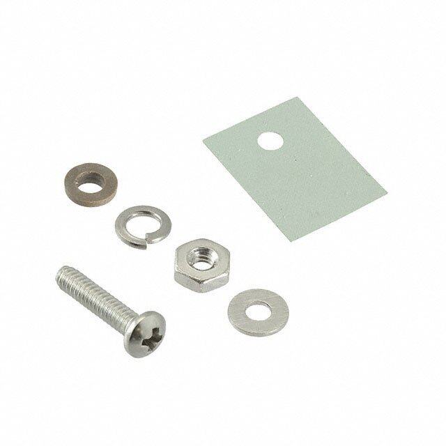
型号为125700D00000G的热敏配件,由Aavid(Boyd Corporation旗下的热管理解决方案部门)生产,主要用于以下应用场景:

 1. 电子设备散热
   - 该型号可能是一种导热垫、导热片或类似的热界面材料(TIM),用于提高电子设备中发热元件(如CPU、GPU、功率放大器等)与散热器之间的热传导效率。
   - 应用场景包括计算机、服务器、网络设备、通信基站和消费类电子产品。

 2. 工业控制设备
   - 在工业自动化领域,该产品可用于变频器、伺服驱动器、PLC控制器等设备的散热管理,确保设备在高温环境下稳定运行。
   - 提供高效的热传递性能,延长设备使用寿命。

 3. 汽车电子系统
   - 适用于新能源汽车(EV/HEV)中的电池管理系统(BMS)、逆变器、车载充电器等高功率电子模块的热管理。
   - 帮助降低关键部件的工作温度,提升系统可靠性和安全性。

 4. 医疗设备
   - 在医疗成像设备(如CT机、MRI设备)、超声波设备或激光治疗仪器中,该型号可用于关键组件的散热,确保设备精确运行并减少热量对敏感元件的影响。

 5. LED照明
   - 用于LED灯具(如路灯、工矿灯、室内照明)的散热设计,帮助将LED芯片产生的热量有效传导至散热器,从而提高光效和灯具寿命。

 6. 航空航天与国防
   - 在极端环境下的航空电子设备、雷达系统或卫星组件中,该产品可提供可靠的热管理解决方案,确保设备在高低温变化中正常工作。

 特性总结:
- 高导热性:有效降低热阻,提高热传导效率。
- 柔软性与压缩性:适应不同表面粗糙度,确保良好接触。
- 电气绝缘:部分型号具备优异的绝缘性能,适合高压环境。
- 耐久性:能够在长时间使用中保持稳定的热传导性能。

具体应用还需结合实际需求和技术参数进行选择和设计。
| 参数 | 数值 |
| 产品目录 | |
| 描述 | SOLDER ANCHOR FOR BGA HEATSINKS散热片 SOLDER ANCHOR MOUNT |
| 产品分类 | |
| 品牌 | Aavid Thermalloy |
| 产品手册 | http://www.aavid.com/products/bga/solder_anchor.html |
| 产品图片 |
|
| rohs | 符合RoHS无铅 / 符合限制有害物质指令(RoHS)规范要求 |
| 产品系列 | Aavid Thermalloy 125700D00000G- |
| mouser_ship_limit | 该产品可能需要其他文件才能进口到中国。 |
| 数据手册 | http://www.aavid.com/sites/default/files/literature/Aavid-Board-Level-Heatsinks-Catalog.pdf#page=112 |
| 产品型号 | 125700D00000G |
| 产品 | Heat Sink Accessories |
| 产品目录页面 | |
| 产品种类 | 散热片 |
| 其它名称 | HS400 |
| 商标 | Aavid Thermalloy |
| 安装风格 | SMD/SMT |
| 宽度 | 2.49 mm |
| 工厂包装数量 | 1000 |
| 散热片材料 | Aluminum |
| 标准包装 | 1,000 |
| 配件类型 | 焊锚(需要 2 个) |
| 配套使用产品/相关产品 | BGA 散热片 |
| 长度 | 7.62 mm |
| 零件号别名 | 042956 |
| 高度 | 7.19 mm |


PDF Datasheet 数据手册内容提取
Table of Contents General Information How to Use This Standard Part Catalog....................................................................................................................................................................................................................2 Index by Part Number.....................................................................................................................................................................................................................................................3 Index by Device and Thermal Resistance............................................................................................................................................................................................................4–5 Index by Style and Thermal Resistance................................................................................................................................................................................................................6–8 How to Select a Heat Sink......................................................................................................................................................................................................................................9–10 How to Read a Thermal Graph...................................................................................................................................................................................................................................11 S Board Mounted Heat Sinks T N Heat Sinks for IC Packages E T BGA.........................................................................................................................................................................................................................................................12–19 N DIP...........................................................................................................................................................................................................................................................21–23 O C Surface Mount Discrete Semiconductor Packages F D-PAK.....................................................................................................................................................................................................................................................24–25 O SO...................................................................................................................................................................................................................................................................24 E L SMT Footprints..........................................................................................................................................................................................................................................26 B Thru-Hole Discrete Semiconductor Packages A T TO-220..................................................................................................................................................................................................................................................27–50 TO-220 and TO-262..........................................................................................................................................................................................................................51–53 TO-220,TO-218,and TO-247.........................................................................................................................................................................................................53–58 TO-220 and TO-202..................................................................................................................................................................................................................................59 TO-220,TO-218,TO-247,and Multiwatt....................................................................................................................................................................................60–61 TO-218..........................................................................................................................................................................................................................................................62 TO-202...................................................................................................................................................................................................................................................63–64 TO-126..........................................................................................................................................................................................................................................................65 SIP............................................................................................................................................................................................................................................................66–67 TO-92.............................................................................................................................................................................................................................................................68 TO-3........................................................................................................................................................................................................................................................69–73 TO-66.............................................................................................................................................................................................................................................................74 TO-5........................................................................................................................................................................................................................................................75–76 Axial Lead Devices....................................................................................................................................................................................................................................77 Bridge Rectifiers........................................................................................................................................................................................................................................77 Options Table of Contents....................................................................................................................................................................................................................................................78–79 How to Decipher an Aavid 13 Digit Part Number..............................................................................................................................................................................................80 How to Decipher a "Thermalloy" Origin Part Number......................................................................................................................................................................................81 Index A,B,C = Aavid Standard Parts w/Options..........................................................................................................................................................................................82–84 Index D = "Thermalloy" Origin Parts w/Options.................................................................................................................................................................................................85 Interface Materials In-Sil™,Kondux™,Grafoil® Pads.............................................................................................................................................................................................................................. 86 Hi-Flow®,Alignment Pads.......................................................................................................................................................................................................................................... 87 Double Sided Tape Options (Factory Applied)....................................................................................................................................................................................................88 Labor Saving Heat Sink to Board and Semiconductor Mounts Wave-On™ Mounts,Semiconductor Mounts,Shur-Lock™ Tabs,Solderable Tabs,Solderable Pins.........................................................................................89–94 Solderable Nuts,Clinch Nuts,Solderable Studs,Device Mounting Studs..........................................................................................................................................94–96 Clips Kool-Klips™.......................................................................................................................................................................................................................................................................97 Thermal Clips....................................................................................................................................................................................................................................................................98 Accessories Mounting Kits........................................................................................................................................................................................................................................................................................99 Insulating Shoulder Washers.........................................................................................................................................................................................................................................................100 Insulators–Thermalfilm™ and Thermalfilm™ MT.........................................................................................................................................................................................................101–102 Insulators–Mica and Thermasil™ III.............................................................................................................................................................................................................................................103 Insulating Washers/Aluminum Oxide.........................................................................................................................................................................................................................................104 Insulating Stanchion Pads..............................................................................................................................................................................................................................................................105 Insulating Covers................................................................................................................................................................................................................................................................................106 Mounting Pads..........................................................................................................................................................................................................................................................................107–109 Finishes..................................................................................................................................................................................................................................................................................................110 Card Ejectors & Guides....................................................................................................................................................................................................................................................................111 Thermal Greases and Epoxies..............................................................................................................................................................................................................................................112–115 1 sales.na@aavid.com www.shopaavid.com
How to Use This Catalog Icons indicate that Base part Semiconductor Style description a mounting kit,grease number device for heat sink or epoxy can be used with the heat sink TO-220 Heat Sinks Grease Mounting 7022 Channel style heat sink with folded back fins Epo&xy Kits page112 page 99 N O Semiconductor devices Thermal graphs show natural and forced Mechanical drawing TI have been included in photos to convection based on black anodize finish. dimensions as shown A assist in determining mounting For information on how to use a thermal graph, are mm (inches) M position. please refer to page 11. R O F N 9.52 LI Air Velocity—Feet Per Minute (0.375) (203.9.0016) A 0 200 400 600 800 1000 50.44 GENER illuDsettraaitleesd t dhees hceriaptt sioinnk’s Mounting Surface TempRise Above Ambient—C°108246000000 503214 Thermal Resistance From MTGSurface to Ambient—C/Watt° (201.8.0238)2xø(03.1.8510) (1.98"6X)" (419.9.9698) differentiating features. 0 4 8 12 16 20 Heat Dissipated—Watts (04.1.8930) 2x 3.81 (104.5.4780) (0.150) 2.02 TAB (0.080) 3.18 2.67 Channel style heat sink with (0.125) (0.105) 2x2.03 folded back finsfor increased 2.29 (0.080) cooling surface area.Available 4.44 (0.090) 24.16 with tin plated solderable tabs (0.175) (0.951) for easy attachment to the Ordering information will Material and finish Material:1.27 (0.050) Thick Aluminum printed circuit card. specify the base heat sink with information is shown Finish:See Table available accessories. for each part ORDERINGINFORMATION Dia of PCB Plated Thru Part Number Description Finish Hole for Tabs 7022BG Channel heat sink with folded back fins Black anodize 7022PBG Channel heat sink with folded back fins Pre-black anodize* 7022B-MTG With solderable tabs Black anodize 2.90 (0.114) 7022PB-MTG With solderable tabs Pre-black anodize* 2.90 (0.114) * Edges cut during the manufacturing process will be unfinished. See page XX for more information Aavid has a large selection of popular POPULAR OPTIONS: 7022B- G options to enhance your heat sink selection. This section will indicate the most popular Base part no. A RoHS Compliant options available. Position Code Description Location Details A TC11-MT Insulated device mounting clip for T0-220 and solderable tabs Hole X Page Detailed indexes are available For additional options see page xx to select additional options. 2 sales.na@aavid.com www.shopaavid.com
Index by Part Number Part Number Page Part Number Page Part Number Page Part Number Page Part Number Page Part Number Page 10-5597-02G 14 374424B00032G 17 530101B00150G 54 574102B00000G 45 581002B02500G 61 7022PB-MTG 29 10-5597-22G 14 374424B00035G 16 530102B00100G 54 574102B03300G 45 581101B02500G 61 7023BG 28 10-5597-33G 14 374424B60023G 12 530102B00150G 54 574204B00000G 63 581102B02500G 61 7023B-MTG 28 10-5607-04G 14 374524B00032G 17 530161B00162G 54 574204B03300G 63 581201B02500G 61 7025BG 27 10-5607-05G 14 374524B00035G 16 530162B00162G 54 574402B00000G 45 581202B02500G 61 7025B-MTG 27 10-5634-01G 12 374524B60023G 12 530401B00100G 55 574402B03200G 45 584000B00000G 67 7038BG 67 10-6326-27G 14 374624B00032G 17 530401B00150G 55 574502B00000G 45 584000B03500G 67 709203B00400G 19 10-6326-28G 14 374624B00035G 16 530402B00100G 55 574502B03300G 45 5900PBG 32 7106DG 24 10-6327-01G 14 374624B60024G 12 530402B00150G 55 574602B00000G 45 590102B03600G 34 7106D/TRG 24 10-BRD1-01G 12 374724B00032G 17 530510B00000G 66 574602B03300G 45 590302B03600G 34 7109DG 25 10-BRD1-03G 12 374724B00035G 16 530510U00000G 66 574802B00000G 43 591202B00000G 51 7109D/TRG 25 10-BRD1-04G 12 374724B60024G 12 530613B00000G 40 574802B03300G 43 591202B03100G 51 7128DG 36 10-BRD1-05G 12 374824B00032G 17 530614B00000G 40 574902B00000G 45 591202B04000G 51 7130DG 62 10-BRD1-07G 12 374824B00035G 16 530714B00000G 40 574902B03300G 45 591302B00000G 51 7136DG 35 10-BRD2-01G 12 374824B60024G 12 530801B05100G 54 575002B00000G 33 591302B02800G 51 7137DG 42 10-CLS1-01G 12 374924B00032G 17 530801B05150G 54 575002D00000G 33 591302B04000G 51 7139DG 35 X 10-CLS2-01G 12 374924B00035G 16 530802B05100G 54 575102B00000G 46 592201B03400G 62 7140DG 42 E 10-L4LB-03G 14 374924B60024G 12 530802B05150G 54 575200B00000G 68 592502B03400G 49 7141DG 38 D 10-L4LB-05G 14 375024B00032G 17 530861B05162G 54 575300B00000G 68 592502U03400G 49 7142DG 36 N 10-L4LB-11G 14 375024B00035G 16 530862B05162G 54 575400B00000G 68 592902B03400G 33 7148DG 67 I 10-THMA-01G 12 375024B60024G 12 531002B02500G 59 575603B00000G 70 593002B03400G 33 7173DG 39 10-TNT2-01G 14 375124B00032G 17 531002V02500G 59 575703B00000G 70 593101B03600G 62 7178DG 35 2317B-EP11-BGS1G 18 375124B00035G 16 531102B02500G 59 575803B00000G 70 593202B03500G 48 799403B01500G 19 2319B-TACHG 17 375124B60024G 12 531102V02500G 59 575903B00000G 70 5FG 75 92FG 68 2321B-TACHG 17 375224B00032G 17 531202B02500G 59 576012B00000G 40 6000DG 77 BW38-2G 58 2327B-CP50G 16 375324B00035G 16 531202V02500G 59 576014B00000G 40 6000UG 77 BW38-4G 58 2327B-TACHG 16 375424B00034G 16 531302B02500G 59 576103B00000G 73 6021BG 30 BW50-2G 58 2332B-TACHG 17 500103B00000G 72 531302V02500G 59 576203B00000G 73 6021PBG 30 BW50-4G 58 2338B-TACHG 17 500203B00000G 72 532602B02500G 50 576303B00000G 73 6022BG 47 BW63-2G 58 2342B-TACHG 17 500303B00000G 72 532702B02500G 50 576403B00000G 73 6022PBG 47 BW63-4G 58 2518B-EP11-BGS2G 18 500403B00000G 72 532802B02500G 50 576602B00000G 33 6025DG 48 ML26AAG 50 2519B-EP11-BGS5G 18 501000B00000G 20 533001B02551G 55 576602D00000G 33 6032DG 47 PF432G 52 2520B-EP04-BGS5G 18 501000J00000G 20 533002B02551G 55 576802B00000G 52 6038BG 36 PF433G 52 2522B-EP04-BGS5G 18 501100B00000G 23 533101B02551G 55 576802B03100G 52 6043PBG 43 PF434G 52 320105B00000G 76 501200B00000G 23 533102B02551G 55 576802B04000G 52 6046PBG 64 PF435G 52 320205B00000G 76 501303B00000G 70 533201B02551G 55 576802V00000G 52 6047PBG 64 PF436G 52 323005B00000G 76 501403B00000G 70 533202B02551G 55 576802V03100G 52 6049PBG 43 PF523G 73 325705B00000G 76 501503B00000G 70 533301B02551G 55 576802V04000G 52 6094PBG 43 PF526G 73 326005B00000G 76 501603B00000G 70 533302B02551G 55 576802U00000G 52 6109PBG 35 PF527G 73 335114B00032G 19 501706B00000G 74 533401B02552G 57 576802U03100G 52 6110PBG 35 PF720G 44 335211B00000G 19 501806B00000G 74 533402B02552G 57 576802U04000G 52 615653B00250G 19 PF723G 44 335211B00032G 19 501906B00000G 74 533421B02552G 57 576904B00000G 64 6201PBG 75 PF730G 65 335214B00000G 19 502006B00000G 74 533422B02552G 57 577002B00000G 34 6202PBG 75 PF732G 65 335214B00032G 19 504102B00000G 38 533501B02552G 57 577002B04000G 34 6203PBG 75 PF750G 44 335214B00034G 19 504222B00000G 38 533502B02552G 57 577102B00000G 34 6221PBG 30 PF752G 44 335224B00032G 17 505103B00000G 72 533521B02552G 57 577102B04000G 34 6222BG 77 PF758G 44 335224B00034G 16 505303B00000G 72 533522B02552G 57 577202B00000G 34 6223BG 77 SW25-2G 56 335314B00000G 19 505403B00000G 72 533601B02552G 57 577202B04000G 34 6224BG 77 SW25-4G 56 335314B00032G 19 506003B00000G 69 533602B02552G 57 577304B00000G 64 6225B-MTG 47 SW25-6G 59 335314B00035G 19 506304B00000G 63 533621B02552G 57 577404B00000G 64 6230DG 30 SW38-2G 56 335324B00032G 16 506902B00000G 41 533622B02552G 57 577500B00000G 65 6232B-MTG 48 SW38-4G 56 335714B00000G 19 507002B00000G 41 533701B02552G 57 577500U00000G 65 6232PB-MTG 48 SW38-6G 59 335714B00032G 19 507102B00000G 41 533702B02552G 57 577922B00000G 40 6236BG 39 SW50-2G 56 335724B00032G 17 507222B00000G 41 533721B02552G 57 578105B00000G 75 6236PBG 39 SW50-4G 56 335814B00000G 19 507302B00000G 38 533722B02552G 57 578205B00000G 75 6237BG 42 SW63-2G 56 335814B00032G 19 507302J00000G 38 533802B02554G 50 578305B00000G 75 6237PBG 42 SW63-4G 56 335824B00032G 17 508500B00000G 23 533902B02554G 50 578405B00000G 75 6238BG 37 TV1500G 32 335824B00034G 16 508600B00000G 23 534002B02554G 50 578505B00000G 75 6238B-MTG 37 TV1505G 32 336314B00000G 19 508700B00000G 23 534202B02853G 37 578622B03200G 40 6239B-MTG 37 TV265G 32 336624B00032G 17 513001B02500G 58 534202B03453G 37 579003B00000G 71 6284BG 23 TV35G 31 364424B00032G 17 513002B02500G 58 542502B00000G 49 579103B00000G 69 6374BG 61 TV4G 65 364424B00034G 16 513101B02500G 58 542502D00000G 49 579103V00000G 69 6380BG 60 TV40G 39 371824B00032G 17 513102B02500G 58 551002B00000G 29 579206B00000G 74 6381BG 60 TV46G 31 371824B00034G 16 513201B02500G 58 560200B00000G 20 579206V00000G 74 6382BG 60 TV47G 31 372024B00032G 17 513202B02500G 58 560200W00000G 20 579302B00000G 46 6396BG 60 TV58G 31 372024B00034G 16 513301B02500G 58 563002B00000G 33 579402B00000G 46 6396B-P2G 60 TV96G 53 372924M02000G 14 513302B02500G 58 563002D00000G 33 579604B00000G 63 6398BG 60 TV97G 53 373024B00032G 17 519703B00000G 71 566010B00000G 66 579604B03300G 63 6398B-P2G 60 YB32-4G 61 373024B00034G 16 519803B00000G 71 566010B03100G 66 579704B00000G 63 6399BG 60 373224M00032G 17 519903B00000G 71 566010B03400G 66 579704B03300G 63 6399B-P2G 60 373324M00032G 17 520103B00000G 71 566902B00000G 53 579802B00000G 43 6400BG 60 374024B00032G 17 520327B00000G 69 566902B03100G 53 579802B03300G 43 6400B-P2G 60 374024B00035G 16 520328B00000G 69 566902B04000G 53 579902B00000G 43 700353U01100G 19 374024B60023G 12 520329B00000G 69 569003B00000G 71 579902B03300G 43 7019BG 27 374124B00032G 17 529701B02500G 56 569022B00000G 42 580100B00000G 20 7019B-MTG 27 374124B00035G 16 529702B02500G 56 573100D00000G 24 580100W00000G 20 7019PBG 27 374124B60023G 12 529801B02500G 56 573100D00010G 24 580200B00000G 20 7020BG 27 374224B00032G 17 529802B02500G 56 573300D00000G 24 580200W00000G 20 7020B-MTG 27 374224B00035G 16 529901B02500G 56 573300D00010G 24 580300B00000G 21 7021BG 28 374224B60023G 12 529902B02500G 56 573400D00000G 25 580400B00000G 22 7021B-MTG 28 374324B00032G 17 530001B02500G 56 573400D00010G 25 580500B00000G 22 7022BG 29 374324B00035G 16 530002B02500G 56 574004B00000G 63 580600B00000G 21 7022B-MTG 29 374324B60023G 12 530101B00100G 54 574004U00000G 63 581001B02500G 61 7022PBG 29 3 sales.na@aavid.com www.shopaavid.com
Index by Device Cooled and Thermal Resistance Board Board Board Board Part Number θn Mounting Page Part Number θn Mounting Page Part Number θn Mounting Page Part Number θn Mounting Page AXIAL LEAD D2PAK TO-263 TO-66 533101B02551G 11.0 V 55 573300D00010G 16.0 H 24 513101B02500G 11.0 V 58 6000UG 15.0 V 77 573300D00000G 16.0 H 24 579206B00000G 22.0 H 74 SW38-2G 10.2 V 56 6000DG 15.0 V 77 7109D/TRG 9.0 H 25 579206V00000G 22.0 H 74 SW38-4G 10.2 V 56 7109DG 9.0 H 25 501706B00000G 12.0 H 74 533201B02551G 9.0 V 55 D2PAK TO-263 SO-10 501806B00000G 9.6 H 74 513201B02500G 9.0 V 58 BRIDGE RECTIFIERS 7106D/TRG 14.0 H 24 501906B00000G 8.0 H 74 SW50-2G 8.8 V 56 7106DG 14.0 H 24 502006B00000G 8.0 H 74 SW50-4G 8.8 V 56 6222BG 9.4 V 77 D3PAK TO-268 593101B03600G 8.6 V 62 6223BG 9.4 V 77 573400D00010G 11.0 H 25 YB32-4G 8.4 V 61 6224BG 9.4 V 77 573400D00000G 11.0 H 25 TO-92 513301B02500G 8.0 V 58 533301B02551G 8.0 V 55 X DIPS TO-3 575200B00000G 60.0 V 68 530001B02500G 8.0 V 56 575300B00000G 50.0 V 68 BW63-4G 7.4 V 58 E D 501200B00000G 68.0 H 23 575603B00000G 15.6 H 70 575400B00000G 40.0 V 68 BW38-2G 7.2 V 58 N 501100B00000G 67.0 H 23 575703B00000G 13.4 H 70 92FG 36.1 V 68 BW38-4G 7.2 V 58 I 501000J00000G 60.0 H 20 579103B00000G 12.5 H 69 SW63-2G 7.0 V 56 501000B00000G 60.0 H 20 579103V00000G 12.5 H 69 SW63-4G 7.0 V 56 580300B00000G 39.0 H 21 501303B00000G 12.0 H 70 TO-126 6380BG 6.8 V 60 580400B00000G 39.0 H 22 519803B00000G 11.4 H 71 592201B03400G 6.8 V 62 508500B00000G 34.0 H 23 575803B00000G 11.0 H 70 530101B00100G 6.3 V 54 508600B00000G 32.0 H 23 PF523G 10.1 H 73 PF730G 35.8 H-V 65 530101B00150G 6.3 V 54 580100B00000G 30.0 H 20 501403B00000G 10.0 H 70 PF732G 35.8 H-V 65 530801B05100G 6.3 V 54 580100W00000G 30.0 H 20 505103B00000G 10.0 H 72 577500B00000G 26.0 V 65 530801B05150G 6.3 V 54 508700B00000G 27.2 H 23 575903B00000G 9.8 H 70 577500U00000G 26.0 V 65 530401B00100G 6.3 V 55 6284BG 25.0 H 23 PF526G 8.9 H 73 TV4G 21.6 H 65 530401B00150G 6.3 V 55 560200B00000G 20.0 H 20 6381BG 5.8 V 60 560200W00000G 20.0 H 20 BW50-2G 5.8 V 58 KEY 580200B00000G 20.0 H 20 BW50-4G 5.8 V 58 580200W00000G 20.0 H 20 H = Horizontal mount 533701B02552G 5.7 V 57 580500B00000G 20.0 H 22 533721B02552G 5.7 V 57 580600B00000G 20.0 H 21 V = Vertical mount 6396BG 5.6 V 60 6396B-P2G 5.6 V 60 IC PACKAGES,BGA,PGA,QFP,LCC H–V = Either horizontal or vertical 529701B02500G 5.5 V 56 6374BG 5.0 V 61 Bi Directional Air Flow H 19 depending on device leads 533401B02552G 5.0 V 57 Solder Anchor H 12 533421B02552G 5.0 V 57 Push Pin H 14 θn = Natural convection thermal resistance 529801B02500G 5.0 V 56 Clip Attachment H 18 based on a 75°C heat sink temperature rise BW63-2G 4.7 V 58 Tape Attachment H 16 529901B02500G 4.5 V 56 533501B02552G 4.5 V 57 533521B02552G 4.5 V 57 MULTIWATT 501503B00000G 8.4 H 70 TO-202 530161B00162G 4.4 V 54 501603B00000G 7.8 H 70 530861B05162G 4.4 V 54 YB32-4G 8.4 V 61 505303B00000G 7.8 H 72 576904B00000G 32.0 H–V 64 6398BG 4.4 V 60 6380BG 6.8 V 60 PF527G 7.4 H 73 574004B00000G 28.0 V 63 6398B-P2G 4.4 V 60 6381BG 5.8 V 60 500103B00000G 7.2 H 72 574004U00000G 28.0 V 63 6382BG 4.2 V 60 6396BG 5.6 V 60 576103B00000G 7.2 H 73 577304B00000G 27.2 H–V 64 533601B02552G 3.8 V 57 6396B-P2G 5.6 V 60 506003B00000G 7.0 H 69 6046PBG 25.0 V 64 533621B02552G 3.8 V 57 6374BG 5.0 V 61 500203B00000G 6.2 H 72 6047PBG 25.0 V 64 6399BG 3.3 V 60 6398BG 4.4 V 60 576203B00000G 6.2 H 73 579604B00000G 24.0 V 63 6399B-P2G 3.3 V 60 6398B-P2G 4.4 V 60 579003B00000G 6.0 H 71 579604B03300G 24.0 V 63 6400BG 2.7 V 60 6382BG 4.2 V 60 505403B00000G 6.0 H 72 579704B00000G 24.0 V 63 6400B-P2G 2.7 V 60 6399BG 3.3 V 60 576303B00000G 6.0 H 73 579704B03300G 24.0 V 63 6399B-P2G 3.3 V 60 500303B00000G 5.8 H 72 577404B00000G 24.0 H–V 64 6400BG 2.7 V 60 569003B00000G 5.5 H 71 574204B00000G 16.8 V 63 TO-220 6400B-P2G 2.7 V 60 520103B00000G 5.4 H 71 574204B03300G 16.8 V 63 576403B00000G 5.1 H 73 506304B00000G 14.4 H–V 63 6094PBG 40.5 H 43 500403B00000G 5.0 H 72 531002B02500G 13.4 V 59 PF730G 35.8 V 65 SIPS 519703B00000G 4.8 H 71 531002V02500G 13.4 V 59 PF732G 35.8 V 65 520329B00000G 4.7 H 69 SW25-6G 13.0 V 59 7178DG 35.7 V 35 530510U00000G 20.6 V 66 520328B00000G 4.7 H 69 531102B02500G 10.4 V 59 6049PBG 34.1 V 43 530510B00000G 20.6 V 66 520327B00000G 4.7 H 69 531102V02500G 10.4 V 59 576802V00000G 32.6 V 52 7038BG 16.0 V 67 519903B00000G 4.2 H 71 SW38-6G 10.0 V 59 576802U00000G 32.6 V 52 7148DG 16.0 V 67 531302B02500G 8.0 V 59 576802V03100G 32.6 H 52 566010B00000G 11.5 H-V 66 TO-5 531302V02500G 8.0 V 59 576802U03100G 32.6 H 52 566010B03400G 11.5 V 66 531202V02500G 7.5 V 59 576802V04000G 32.6 V 52 566010B03100G 11.5 H 66 320105B00000G 63.0 V 76 531202B02500G 7.5 V 59 576802U04000G 32.6 V 52 584000B00000G 10.0 V 67 320205B00000G 63.0 V 76 577002B00000G 32.0 H–V 34 584000B03500G 10.0 V 67 325705B00000G 60.0 V 76 TO-218 577002B04000G 32.0 V 34 6380BG 6.8 V 60 326005B00000G 57.0 V 76 TV58G 29.9 H–V 31 6381BG 5.8 V 60 323005B00000G 56.0 V 76 TV96G 24.0 H 53 PF720G 28.9 V 44 6382BG 4.2 V 60 6201PBG 54.0 V 75 7130DG 23.1 V 62 PF723G 28.9 V 44 5FG 45.2 V 75 TV97G 20.0 H 53 7139DG 28.3 H 35 6202PBG 43.0 V 75 581001B02500G 19.6 V 61 576802B00000G 27.3 V 52 SMT 578105B00000G 40.0 V 75 581101B02500G 16.8 V 61 576802B03100G 27.3 H 52 578205B00000G 38.0 V 75 581201B02500G 12.8 V 61 576802B04000G 27.3 V 52 D-PAK TO-252 6203PBG 38.0 V 75 513001B02500G 13.4 V 58 TV46G 27.1 H–V 31 573100D00010G 25.0 H 24 578305B00000G 35.0 V 75 533001B02551G 13.0 V 55 TV47G 27.1 H–V 31 573100D00000G 25.0 H 24 578405B00000G 31.0 V 75 SW25-2G 11.4 V 56 591202B00000G 26.8 H–V 51 578505B00000G 28.0 V 75 SW25-4G 11.4 V 56 591202B03100G 26.8 H 51 4 sales.na@aavid.com www.shopaavid.com
Index by Device Cooled and Thermal Resistance Board Board Board Board Part Number θn Mounting Page Part Number θn Mounting Page Part Number θn Mounting Page Part Number θn Mounting Page 591202B04000G 26.8 V 51 507102B00000G 15.6 H–V 41 TV35G 7.2 H 31 SW25-2G 11.4 V 56 591302B00000G 26.8 H–V 51 6225B-MTG 15.0 V 47 BW38-2G 7.2 V 58 SW25-4G 11.4 V 56 591302B02800G 26.8 V 51 TV1500G 14.2 V 32 BW38-4G 7.2 V 58 533101B02551G 11.0 V 55 591302B04000G 26.8 H 51 575002B00000G 13.6 V 33 SW63-2G 7.0 V 56 513101B02500G 11.0 V 58 579802B00000G 26.4 V 43 575002D00000G 13.6 V 33 SW63-4G 7.0 V 56 SW38-2G 10.2 V 56 579802B03300G 26.4 V 43 6238BG 13.6 H–V 37 7025BG 6.8 V 27 SW38-4G 10.2 V 56 579902B00000G 26.4 V 43 6238B-MTG 13.6 V 37 7025B-MTG 6.8 V 27 533201B02551G 9.0 V 55 579902B03300G 26.4 V 43 6239B-MTG 13.6 V 37 7021BG 6.8 V 28 513201B02500G 9.0 V 58 577102B00000G 25.9 H–V 34 593002B03400G 13.4 V 33 7021B-MTG 6.8 V 28 SW50-2G 8.8 V 56 577102B04000G 25.9 V 34 534202B02853G 13.4 V 37 6380BG 6.8 V 60 SW50-4G 8.8 V 56 7173DG 25.8 V 39 534202B03453G 13.4 V 37 7022BG 6.5 V 29 YB32-4G 8.4 V 61 6236BG 25.0 V 39 513002B02500G 13.4 V 58 7022PBG 6.5 V 29 533301B02551G 8.0 V 55 6236PBG 25.0 V 39 531002B02500G 13.4 V 59 7022B-MTG 6.5 V 29 530001B02500G 2.6 V 56 X 6237BG 25.0 H 42 531002V02500G 13.4 V 59 7022PB-MTG 6.5 V 29 513301B02500G 8.0 V 58 E 6237PBG 25.0 H 42 577922B00000G 13.2 V 40 504222B00000G 6.4 H 38 BW38-2G 7.2 V 58 D 577202B00000G 24.4 H–V 34 578622B03200G 13.2 V 40 530102B00100G 6.3 V 54 BW38-4G 7.2 V 58 N 577202B04000G 24.4 V 34 TV265G 13.0 V 32 530102B00150G 6.3 V 54 SW63-2G 7.0 V 56 I 507302B00000G 24.0 H–V 38 5900PBG 13.0 V 32 530802B05100G 6.3 V 54 SW63-4G 7.0 V 56 507302J00000G 24.0 H–V 38 563002B00000G 13.0 V 33 530802B05150G 6.3 V 54 6380BG 6.8 V 60 542502B00000G 24.0 H 49 563002D00000G 13.0 V 33 530402B00100G 6.3 V 55 530101B00100G 6.3 V 54 542502D00000G 24.0 H 49 533802B02554G 13.0 V 50 530402B00150G 6.3 V 55 530101B00150G 6.3 V 54 TV96G 24.0 H 53 533002B02551G 13.0 V 55 6381BG 5.8 V 60 530801B05100G 6.3 V 54 PF752G 23.7 V 44 SW25-6G 13.0 V 59 BW50-2G 5.8 V 58 530801B05150G 6.3 V 54 576014B00000G 23.2 H–V 40 581202B02500G 12.8 V 61 BW50-4G 5.8 V 58 530401B00100G 6.3 V 55 574402B00000G 23.2 H–V 45 6021BG 12.5 V 30 533702B02552G 5.7 V 57 530401B00150G 6.3 V 55 574402B03200G 23.2 H 45 6021PBG 12.5 V 30 533722B02552G 5.7 V 57 6381BG 5.8 V 60 574102B00000G 23.2 H–V 45 BW50-2G 5.8 V 58 574102B03300G 23.2 V 45 BW50-4G 5.8 V 58 6043PBG 23.0 V 43 NEED HIGHER PERFORMANCE? 533701B02552G 5.7 V 57 592502B03400G 22.0 V 49 533721B02552G 5.7 V 57 592502U03400G 22.0 V 49 Aavid also offers the Max Clip SystemTM 6396BBG 5.6 V 60 574602B00000G 21.6 H–V 45 6396B-P2G 5.6 V 60 574602B03300G 21.6 V 45 for discrete power semiconductors 529701B02500G 5.5 V 56 574502B00000G 21.2 H–V 45 6374BG 5.0 V 61 574502B03300G 21.2 V 45 featuring simple assembly and high 533401B02552G 5.0 V 57 6110PBG 21.0 H–V 35 533421B02552G 5.0 V 57 reliability. 576012B00000G 20.8 H–V 40 529801B02500G 5.0 V 56 7137DG 20.8 V 42 BW63-2G 4.7 V 58 7140DG 20.8 H 42 BW63-4G 4.7 V 58 574802B00000G 20.4 H–V 43 529901B02500G 4.5 V 56 574802B03300G 20.4 V 43 533501B02552G 4.5 V 57 PF750G 20.3 V 44 533521B02552G 4.5 V 57 7142DG 20.3 H 36 6221PBG 12.5 V 30 6396BG 5.6 V 60 6398BG 4.4 V 60 7141DG 20.3 V 38 6230DG 12.5 V 30 6396B-P2G 5.6 V 60 6398B-P2G 4.4 V 60 530714B00000G 20.3 H–V 40 551002B00000G 12.4 H 29 569022B00000G 5.5 H 42 530161B00162G 4.4 V 54 PF432G 20.3 V 52 SW25-2G 11.4 V 56 532602B02500G 5.5 V 50 530861B05162G 4.4 V 54 PF433G 20.3 V 52 SW25-4G 11.4 V 56 529702B02500G 5.5 V 56 6382BG 4.2 V 60 PF434G 20.3 H 52 590302B03600G 11.2 V 34 6374BG 5.0 V 61 533601B02552G 3.8 V 57 PF435G 20.3 V 52 7019BG 11.0 V 27 533402B02552G 5.0 V 57 533621B02552G 3.8 V 57 PF436G 20.3 H 52 7019PBG 11.0 V 27 533422B02552G 5.0 V 57 6399BG 3.3 V 60 506902B00000G 20.0 V 41 7019B-MTG 11.0 V 27 532702B02500G 4.8 V 50 6399B-P2G 3.3 V 60 TV97G 20.0 H–V 53 533902B02554G 11.0 V 50 BW63-2G 4.7 V 58 6400BG 2.7 V 60 7136DG 19.7 V 35 513102B02500G 11.0 V 58 BW63-4G 4.7 V 58 6400B-P2G 2.7 V 60 7128DG 19.2 V 36 533102B02551G 11.0 V 55 529902B02500G 4.5 V 56 566902B00000G 18.8 H-V 53 593202B03500G 10.4 V 48 533502B02552G 4.5 V 57 566902B03100G 18.8 H 53 531102B02500G 10.4 V 59 7023BG 4.4 V 28 TO-262 566902B04000G 18.8 V 53 531102V02500G 10.4 V 59 7023B-MTG 4.4 V 28 6038BG 18.0 V 36 SW38-2G 10.2 V 56 530162B00162G 4.4 V 54 576802B00000G 27.3 H–V 52 592902B03400G 17.9 V 33 SW38-4G 10.2 V 56 530862B05162G 4.4 V 54 576802V00000G 32.6 H–V 52 6025DG 17.9 V 48 590102B03600G 10.0 V 34 6398BG 4.4 V 60 576802U00000G 32.6 H–V 52 6025B-TTG 17.9 V 48 6232B-MTG 10.0 V 48 6398B-P2G 4.4 V 60 576802B03100G 27.3 H 52 ML26AAG 17.9 H 50 6232PB-MTG 10.0 V 48 532802B02500G 4.2 V 50 576802V03100G 32.6 H 52 581002B02500G 17.4 V 61 SW38-6G 10.0 V 59 6382BG 4.2 V 60 576802U03100G 32.6 H 52 PF758G 17.3 V 44 TV40G 9.9 H 39 533602B02552G 3.8 V 57 576802B04000G 27.3 V 52 TV1505G 17.0 V 32 507222B00000G 9.6 H 41 533622B02552G 5.0 V 57 576802V04000G 32.6 V 52 6109PBG 17.0 H–V 35 534002B02554G 9.0 V 50 6399BG 5.0 V 60 576802U04000G 32.6 V 52 575102B00000G 16.8 H–V 46 533202B02551G 9.0 V 55 529802B02500G 3.7 V 56 591202B00000G 26.8 H-V 51 579302B00000G 16.8 V 46 513202B02500G 9.0 V 58 6399B-P2G 3.3 V 60 591202B03100G 26.8 H 51 579402B00000G 16.8 V 46 SW50-2G 8.8 V 56 6400BG 2.7 V 60 591202B04000G 26.8 V 51 581102B02500G 16.8 V 61 SW50-4G 8.8 V 56 6400B-P2G 2.7 V 60 591302B00000G 26.8 H-V 51 530614B00000G 16.7 H–V 40 7020BG 8.7 V 27 533522B02552G 2.7 V 57 591302B02800G 26.8 V 51 530613B00000G 16.7 H–V 40 7020B-MTG 8.7 V 27 530002B02500G 2.6 V 56 591302B04000G 26.8 H 51 6022PBG 16.7 V 47 YB32-4G 8.4 V 61 PF432G 20.3 V 52 6022BG 16.7 V 47 6032DG 8.3 V 47 PF433G 20.3 V 52 576602B00000G 16.6 V 33 533302B02551G 8.0 V 55 TO-247 PF434G 20.3 H 52 576602D00000G 16.6 V 33 513302B02500G 8.0 V 58 PF435G 20.3 V 52 574902B00000G 16.0 H–V 45 531302B02500G 8.0 V 59 TV96G 24.0 H 53 PF436G 20.3 H 52 574902B03300G 16.0 V 45 531302V02500G 8.0 V 59 TV97G 20.0 H–V 53 566902B00000G 18.8 H-V 53 504102B00000G 15.6 H–V 38 531202V02500G 7.5 V 59 513001B02500G 13.4 V 58 566902B03100G 18.8 H 53 507002B00000G 15.6 H–V 41 531202B02500G 7.5 V 59 533001B02551G 13.0 V 55 566902B04000G 18.8 V 53 5 sales.na@aavid.com www.shopaavid.com
Index by Device Cooled,Heat Sink Style,and Thermal Resistance Board Board Board Part Number θn Mounting Page Part Number θn MountingPage Part Number θn Mounting Page AXIAL LEAD SMT TO-5 6000UG 15.0 V 77 D-Pak TO-252 Extruded Collar Heat Sinks 6000DG 15.0 V 77 573100D00010G 15.0 H 24 320105B00000G 63.0 V 76 573100D00000G 15.0 H 24 320205B00000G 63.0 V 76 BRIDGE RECTIFIERS D2Pak TO-263 325705B00000G 60.0 V 76 573300D00010G 18.0 H 24 326005B00000G 57.0 V 76 6222BG 9.4 V 77 573300D00000G 18.0 H 24 323005B00000G 56.0 V 76 6223BG 9.4 V 77 7109D/TRG 11.0 H 25 Low Cost Push On Heat Sink 6224BG 9.4 V 77 7109DG 11.0 H 25 5FG 45.2 V 75 D2Pak TO-263 SO10 (MO-184) Snap On Cooler Heat Sinks DIPS X 7106D/TRG 15.0 H 24 578105B00000G 40.0 V 75 E Extruded Heat Sinks 7106DG 15.0 H 24 578205B00000G 38.0 V 75 D 501200B00000G 68.0 H 23 D3Pak TO-268 578305B00000G 35.0 V 75 N I 501100B00000G 67.0 H 23 573400D00010G 14.0 H 25 578405B00000G 31.0 V 75 508700B00000G 27.2 H 23 573400D00000G 14.0 H 25 578505B00000G 28.0 V 75 6284BG 25.0 H 23 Space Saving Collar Heat Sinks 580500B00000G 20.0 H 22 TO-3 6201PBG 54.0 V 75 580600B00000G 20.0 H 21 6202PBG 43.0 V 75 Slide On Heat Sinks Diamond Shaped Basket Heat Sinks 6203PBG 38.0 V 75 501000J00000G 60.0 H 20 575603B00000G 15.6 H 70 501000B00000G 60.0 H 20 575703B00000G 13.4 H 70 TO-66 580300B00000G 39.0 H 21 501303B00000G 12.0 H 70 580400B00000G 39.0 H 22 Diamond Shaped Basket Heat Sinks 508500B00000G 34.0 H 23 501706B00000G 12.0 H 74 508600B00000G 32.0 H 23 KEY 501806B00000G 9.6 H 74 580100B00000G 30.0 H 20 501906B00000G 8.0 H 74 H = Horizontal mount 580100W00000G 30.0 H 20 502006B00000G 8.0 H 74 560200B00000G 20.0 H 20 Space Saving Collar Heat Sinks V = Vertical mount 560200W00000G 20.0 H 20 579206B00000G 22.0 H 74 580200B00000G 20.0 H 20 H–V = Either horizontal or vertical 579206V00000G 22.0 H 74 580200W00000G 20.0 H 20 depending on device leads TO-92 IC PACKAGES,BGA,PGA,QFP,LCC θn = Natural convection thermal resistance Bi Directional Air Flow H 19 Clip On Style Heat Sink based on a 75°C heat sink temperature rise Solder Anchor H 12 92FG 36.1 V 68 Push Pin H 14 Slip On Style Heat Sinks Clip Attachment H 18 575200B00000G 60.0 V 68 Tape Attachment H 16 575300B00000G 50.0 V 68 575803B00000G 11.0 H 70 575400B00000G 40.0 V 68 MULTI-WATT PF523G 10.1 H 73 Extruded Heat Sinks 501403B00000G 10.0 H 70 TO-126 YB32-4G 8.4 V 61 575903B00000G 9.8 H 70 6380BG 6.8 V 60 PF526G 8.9 H 73 Channel Style Heat Sink 6381BG 5.8 V 60 501503B00000G 8.4 H 70 TV4G 21.6 H 65 6396BG 5.6 V 60 501603B00000G 7.8 H 70 Slip On Style Heat Sinks 6396B-P2G 5.6 V 60 PF527G 7.4 H 73 PF730G 35.8 H-V 65 6374BG 5.0 V 61 Hat Section Heat Sink PF732G 35.8 H-V 65 6398BG 4.4 V 60 506003B00000G 7.0 H 69 577500B00000G 26.0 V 65 6398B-P2G 4.4 V 60 Space Saving Collar Heat Sinks 577500U00000G 26.0 V 65 6382BG 4.2 V 60 579103B00000G 12.5 H 69 6399BG 3.3 V 60 579103V00000G 12.5 H 69 TO-202 6399B-P2G 3.3 V 60 Square Basket Heat Sinks 6400BG 2.7 V 60 519803B00000G 11.4 H 71 Channel Style Heat Sinks 6400B-P2G 2.7 V 60 505103B00000G 10.0 H 72 576904B00000G 32.0 H–V 64 505303B00000G 7.8 H 72 577304B00000G 27.2 H–V 64 SIPS 500103B00000G 7.2 H 72 577404B00000G 24.0 H–V 64 Channel Style Heat Sinks 576103B00000G 7.2 H 73 Compact Slide On Heat Sinks 530510U00000G 20.6 V 66 500203B00000G 6.2 H 72 6046PBG 25.0 V 64 530510B00000G 20.6 V 66 576203B00000G 6.2 H 73 6047PBG 25.0 V 64 Clip On Style Heat Sinks 579003B00000G 6.0 H 71 Extruded Heat Sinks 584000B00000G 10.0 V 67 505403B00000G 6.0 H 72 531002B02500G 13.4 V 59 584000B03500G 10.0 V 67 576303B00000G 6.0 H 73 531002V02500G 13.4 V 59 Extruded Heat Sinks 500303B00000G 5.8 H 72 SW25-6G 13.0 V 59 6380BG 6.8 V 60 569003B00000G 5.5 H 71 531102B02500G 10.4 V 59 6381BG 5.8 V 60 520103B00000G 5.4 H 71 531102V02500G 10.4 V 59 6382BG 4.2 V 60 576403B00000G 5.1 H 73 SW38-6G 10.0 V 59 Plug In Style Heat Sinks 500403B00000G 5.0 H 72 531302B02500G 8.0 V 59 566010B00000G 11.5 H–V 66 519703B00000G 4.8 H 71 531302V02500G 8.0 V 59 566010B03400G 11.5 V 66 519903B00000G 4.2 H 71 531202V02500G 7.5 V 59 566010B03100G 11.5 H 66 Two Piece Heat Sinks 531202B02500G 7.5 V 59 Slide On Style Heat Sinks 520329B00000G 4.7 H 69 Low Cost Slide On Heat Sinks 7038BG 16.0 V 67 520328B00000G 4.7 H 69 574004B00000G 28.0 V 63 7148DG 16.0 V 67 520327B00000G 4.7 H 69 574004U00000G 28.0 V 63 6 sales.na@aavid.com www.shopaavid.com
Index by Device Cooled,Heat Sink Style,and Thermal Resistance Board Board Board Part Number θn Mounting Page Part Number θn Mounting Page Part Number θn Mounting Page TO-202 CONTINUED Hat Section Heat Sinks 534202B02853G 13.4 V 38 TV96G 24.0 H 53 534202B03453G 13.4 V 38 Low Cost Slide On Cooler Heat Sinks TV97G 20.0 H–V 53 577922B00000G 13.2 V 41 579604B00000G 24.0 V 63 High Rise Style Heat Sinks 578622B03200G 13.2 V 41 579604B03300G 24.0 V 63 530101B00100G 6.3 V 54 563002B00000G 13.0 V 34 579704B00000G 24.0 V 63 530101B00150G 6.3 V 54 563002D00000G 13.0 V 34 579704B03300G 24.0 V 63 530801B05100G 6.3 V 54 TV265G 13.0 V 32 574204B00000G 16.8 V 63 530801B05150G 6.3 V 54 5900PBG 13.0 V 32 574204B03300G 16.8 V 63 530401B00100G 6.3 V 55 6021BG 12.5 V 30 Low Profile Hat Section Heat Sink 530401B00150G 6.3 V 55 6021PBG 12.5 V 30 506304B00000G 14.4 H–V 63 Plug In Style Heat Sink 6221PBG 12.5 V 30 Space Saving Staggered Heat Sink 592201B03400G 6.8 V 62 6230DG 12.5 V 30 X E 6034DG 8.3 V 64 Slide On Heat Sink 551002B00000G 12.4 H 30 D 7130DG 23.1 V 62 590302B03600G 11.2 V 34 N TO-218 7019BG 11.0 V 27 I TO-220 7019PBG 11.0 V 27 Channel Style Heat Sink 7019B-MTG 11.0 V 27 593101B03600G 8.6 V 62 Channel Style Heat Sinks 590102B03600G 10.0 V 34 Dual Extruded Heat Sinks 7178DG 35.7 V 35 TV40G 9.9 H 39 533721B02552G 5.7 V 57 577002B04000G 32.0 V 35 7020BG 8.7 V 27 533421B02552G 5.0 V 57 577002B00000G 32.0 H-V 35 7020B-MTG 8.7 V 27 533521B02552G 4.5 V 57 TV58G 29.9 H-V 31 TV35G 7.2 H 31 533621B02552G 3.8 V 57 7139DG 28.3 H 35 7025BG 6.8 V 27 Dual High Rise Style Heat Sinks 7025B-MTG 6.8 V 27 530161B00162G 4.4 V 54 7021BG 6.8 V 28 530861B05162G 4.4 V 54 NEED HIGHER PERFORMANCE? 7021B-MTG 6.8 V 28 Extruded Heat Sinks 7022BG 6.5 V 29 581001B02500G 19.6 V 61 Aavid also offers the Max Clip 7022PBG 6.5 V 29 581101B02500G 16.8 V 61 7022B-MTG 6.5 V 29 513001B02500G 13.4 V 58 SystemTM for discrete power 7022PB-MTG 6.5 V 29 533001B02551G 13.0 V 55 semiconductors featuring simple 504222B00000G 6.4 H 39 581201B02500G 12.8 V 61 7023BG 4.4 V 28 assembly and high reliability. SW25-2G 11.4 V 56 7023B-MTG 4.4 V 28 SW25-4G 11.4 V 56 Clip On Style Heat Sinks 533101B02551G 11.0 V 55 6094PBG 40.5 H 43 513101B02500G 11.0 V 58 6049PBG 34.1 V 43 SW38-2G 10.2 V 56 579802B00000G 26.4 V 44 SW38-4G 10.2 V 56 579802B03300G 26.4 V 44 533201B02551G 9.0 V 55 TV46G 27.1 H–V 31 579902B00000G 26.4 V 44 513201B02500G 9.0 V 58 TV47G 27.1 H–V 31 579902B03300G 26.4 V 44 SW50-2G 8.8 V 56 577102B00000G 25.9 H-V 35 6043PBG 23.0 V 43 SW50-4G 8.8 V 56 577102B04000G 25.9 V 35 574802B00000G 20.4 H–V 44 YB32-4G 8.4 V 61 7173DG 25.8 V 39 574802B03300G 20.4 V 44 533301B02551G 8.0 V 55 6236BG 25.0 V 39 Dual Extruded Heat Sinks 530001B02500G 8.0 V 56 6236PBG 25.0 V 39 6380BG 6.8 V 60 513301B02500G 8.0 V 58 577202B00000G 24.4 H-V 35 6381BG 5.8 V 60 BW63-4G 7.4 V 58 577202B04000G 24.4 V 35 533722B02552G 5.7 V 57 BW38-2G 7.2 V 58 507302B00000G 24.0 H-V 39 533422B02552G 5.0 V 57 BW38-4G 7.2 V 58 507302J00000G 24.0 H-V 39 6374BG 5.0 V 61 SW63-2G 7.0 V 56 576014B00000G 23.2 H-V 41 6382BG 4.2 V 60 SW63-4G 7.0 V 56 6110PBG 21.0 H-V 35 533622B02552G 3.8 V 57 6380BG 6.8 V 60 576012B00000G 20.8 H-V 41 533522B02552G 2.7 V 57 BW50-2G 5.8 V 58 7142DG 20.3 H 36 Dual High Rise Style Heat Sinks BW50-4G 5.8 V 58 7141DG 20.3 V 38 530162B00162G 4.4 V 54 6381BG 5.8 V 60 530714B00000G 20.3 H-V 41 530862B05162G 4.4 V 54 533701B02552G 5.7 V 57 7136DG 19.7 V 35 Extruded Heat Sinks 6396BG 5.6 V 60 7128DG 19.2 V 36 ML26AAG 17.9 H 50 6396B-P2G 5.6 V 60 6038BG 18.0 V 36 581002B02500G 17.4 V 61 529701B02500G 5.5 V 56 592902B03400G 17.9 V 33 581102B02500G 16.8 V 61 533401B02552G 5.0 V 57 6109PBG 17.0 H-V 35 513002B02500G 13.4 V 58 529801B02500G 5.0 V 56 TV1505G 17.0 V 32 531002B02500G 13.4 V 59 BW63-2G 4.7 V 58 530614B00000G 16.7 H-V 41 531002V02500G 13.4 V 59 529901B02500G 4.5 V 56 530613B00000G 16.7 H-V 41 533802B02554G 13.0 V 50 533501B02552G 4.5 V 57 576602B00000G 16.6 V 34 533002B02551G 13.0 V 55 6398BG 4.4 V 60 576602D00000G 16.6 V 34 SW25-6G 13.0 V 59 6398B-P2G 4.4 V 60 504102B00000G 15.6 H–V 39 581202B02500G 12.8 V 61 6382BG 4.2 V 60 TV1500G 14.2 V 32 SW25-2G 11.4 V 56 533601B02552G 3.8 V 57 575002B00000G 13.6 V 34 SW25-4G 11.4 V 56 6399BG 3.3 V 60 575002D00000G 13.6 V 34 533902B02554G 11.0 V 50 6399B-P2G 3.3 V 60 6238BG 13.6 H–V 37 533102B02551G 11.0 V 55 6400BG 2.7 V 60 6238B-MTG 13.6 V 37 513102B02500G 11.0 V 58 6400B-P2G 2.7 V 60 6239B-MTG 13.6 V 37 531102B02500G 10.4 V 59 6374BG 5.0 V 61 593002B03400G 13.4 V 33 531102V02500G 10.4 V 59 7 sales.na@aavid.com www.shopaavid.com
Index by Device Cooled,Heat Sink Style,and Thermal Resistance Board Board Board Part Number θn Mounting Page Part Number θn Mounting Page Part Number θn Mounting Page TO-220 CONTINUED 591302B04000G 26.8 H 51 533101B02551G 11.0 V 55 PF432G 20.3 V 52 513101B02500G 11.0 V 58 SW38-2G 10.2 V 56 PF433G 20.3 V 52 SW38-2G 10.2 V 56 SW38-4G 10.2 V 56 PF434G 20.3 H 52 SW38-4G 10.2 V 56 SW38-6G 10.0 V 59 PF435G 20.3 V 52 533201B02551G 9.0 V 55 534002B02554G 9.0 V 50 PF436G 20.3 H 52 513201B02500G 9.0 V 58 533202B02551G 9.0 V 55 566902B00000G 18.8 H-V 53 SW50-2G 8.8 V 56 513202B02500G 9.0 V 58 566902B03100G 18.8 H 53 SW50-4G 8.8 V 56 SW50-2G 8.8 V 56 566902B04000G 18.8 V 53 YB32-4G 8.4 V 61 SW50-4G 8.8 V 56 Slide On Heat Sinks 533301B02551G 8.0 V 55 YB32-4G 8.4 V 61 PF730G 35.8 V 65 530001B02500G 8.0 V 56 533302B02551G 8.0 V 55 PF732G 35.8 V 65 513301B02500G 8.0 V 58 530002B02500G 2.6 V 56 PF720G 28.9 V 44 BW38-2G 7.2 V 58 X 513302B02500G 8.0 V 58 PF723G 28.9 V 44 BW38-4G 7.2 V 58 E 531302B02500G 8.0 V 59 PF752G 23.7 V 44 SW63-2G 7.0 V 56 D 531302V02500G 8.0 V 59 N 531202V02500G 7.5 V 59 574402B00000G 23.2 H-V 45 SW63-4G 7.0 V 56 I 574402B03200G 23.2 H 45 6380BG 6.8 V 60 531202B02500G 7.5 V 59 574102B00000G 23.2 H–V 45 BW50-2G 5.8 V 58 BW38-2G 7.2 V 58 574102B03300G 23.2 V 45 BW50-4G 5.8 V 58 BW38-4G 7.2 V 58 574602B00000G 21.6 H-V 45 6381BG 5.8 V 60 SW63-2G 7.0 V 56 574602B03300G 21.6 V 45 533701B02552G 5.7 V 57 SW63-4G 7.0 V 56 574502B00000G 21.2 H-V 45 6396BG 5.6 V 60 BW50-2G 5.8 V 58 574502B03300G 21.2 V 45 6396B-P2G 5.6 V 60 BW50-4G 5.8 V 58 PF750G 20.3 V 44 529701B02500G 5.5 V 56 533702B02552G 5.7 V 57 PF758G 17.3 V 44 533401B02552G 5.0 V 57 6396BG 5.6 V 60 574902B00000G 16.0 H-V 45 6374BG 5.0 V 61 6396B-P2G 5.6 V 60 574902B03300G 16.0 V 45 529801B02500G 5.0 V 56 532602B02500G 5.5 V 50 BW63-2G 4.7 V 58 529702B02500G 5.5 V 56 KEY BW63-4G 4.7 V 58 533402B02552G 5.0 V 57 529901B02500G 4.5 V 56 532702B02500G 4.8 V 50 H = Horizontal mount 533501B02552G 4.5 V 57 BW63-2G 4.7 V 58 6398BG 4.4 V 60 BW63-4G 4.7 V 58 V = Vertical mount 6398B-P2G 4.4 V 60 529902B02500G 4.5 V 56 H–V = Either horizontal or vertical 6382BG 4.2 V 60 533502B02552G 4.5 V 57 533601B02552G 3.8 V 57 6398BG 4.4 V 60 depending on device leads 6399BG 3.3 V 60 6398B-P2G 4.4 V 60 532802B02500G 4.2 V 50 θn = Natural convection thermal resistance 6399B-P2G 3.3 V 60 6400BG 2.7 V 60 533602B02552G 3.8 V 57 based on a 75°C heat sink temperature rise 6400B-P2G 2.7 V 60 529802B02500G 3.7 V 56 Hat Section Heat Sinks 6399BG 3.3 V 60 Snap Down Style Heat Sinks TV96G 24.0 H 53 6399B-P2G 3.3 V 60 575102B00000G 16.8 H–V 46 TV97G 20.0 H–V 53 6400BG 2.7 V 60 579302B00000G 16.8 V 46 High Rise Style Heat Sinks 6400B-P2G 2.7 V 60 579402B00000G 16.8 V 46 530101B00100G 6.3 V 54 Hat Section Heat Sinks Space Saving Heat Sinks 530101B00150G 6.3 V 54 6237BG 25.0 H 42 542502B00000G 24.0 H 49 530801B05100G 6.3 V 54 6237PBG 25.0 H 42 542502D00000G 24.0 H 49 530801B05150G 6.3 V 54 TV96G 24.0 H 53 592502B03400G 22.0 V 49 530401B00100G 6.3 V 55 7137DG 20.8 V 42 592502U03400G 22.0 V 49 530401B00150G 6.3 V 55 7140DG 20.8 H 42 6025DG 17.9 V 48 506902B00000G 20.0 V 42 6022PBG 16.7 V 47 TO-262 TV97G 20.0 H–V 53 6022BG 16.7 V 47 507002B00000G 15.6 H–V 42 6225B-MTG 15.0 V 47 Plug In Style Heat Sinks 507102B00000G 15.6 H–V 42 593202B03500G 10.4 V 48 576802B00000G 27.3 H–V 52 507222B00000G 9.6 H 42 6232B-MTG 10.0 V 48 576802V00000G 32.6 H–V 52 High Rise Style Heat Sinks 6232PB-MTG 10.0 V 48 576802U00000G 32.6 H–V 52 530102B00100G 6.3 V 54 6032DG 8.3 V 47 576802B03100G 27.3 H 52 530102B00150G 6.3 V 54 Square Basket Heat Sink 576802V03100G 32.6 H 52 530802B05100G 6.3 V 54 569022B00000G 5.5 H 42 576802U03100G 32.6 H 52 530802B05150G 6.3 V 54 576802B04000G 27.3 V 52 530402B00100G 6.3 V 55 576802V04000G 32.6 V 52 530402B00150G 6.3 V 55 TO-247 576802U04000G 32.6 V 52 Plug In Style Heat Sinks 591202B00000G 26.8 H-V 51 576802B00000G 27.3 V 52 Dual Extruded Heat Sinks 591202B03100G 26.8 H 51 576802V00000G 32.6 V 52 533721B02552G 5.7 V 57 591202B04000G 26.8 V 51 576802U00000G 32.6 V 52 533421B02552G 5.0 V 57 591302B00000G 26.8 H-V 51 576802B03100G 27.3 H 52 533521B02552G 4.5 V 57 591302B02800G 26.8 V 51 576802V03100G 32.6 H 52 533621B02552G 3.8 V 57 591302B04000G 26.8 H 51 576802U03100G 32.6 H 52 Dual High Rise Style Heat Sinks 566902B00000G 18.8 H-V 53 576802B04000G 27.3 V 52 530161B00162G 4.4 V 54 566902B03100G 18.8 H 53 576802V04000G 32.6 V 52 530861B05162G 4.4 V 54 566902B04000G 18.8 V 53 576802U04000G 32.6 V 52 Extruded Heat Sinks PF432G 20.3 V 52 591202B00000G 26.8 H-V 51 513001B02500G 13.4 V 58 PF433G 20.3 V 52 591202B03100G 26.8 H 51 533001B02551G 13.0 V 55 PF434G 20.3 H 52 591202B04000G 26.8 V 51 SW25-2G 11.4 V 56 PF435G 20.3 V 52 591302B00000G 26.8 H-V 51 SW25-4G 11.4 V 56 PF436G 20.3 H 52 591302B02800G 26.8 V 51 8 sales.na@aavid.com www.shopaavid.com
How To Select a Heat Sink How to select a heat sink The basic equation for heat transfer or power dissipation may be stated as follows: ΔT P = D ΣR K θ N I S Where: T PD = the power dissipated by the semiconductor device in watts. A E H ΔT = the temperature difference of driving potential which causes the flow of heat. A ΣRθ = the sum of the thermal resistances of the heat flow path across which ΔT exists. T C The above relationship may be stated in the following forms: E L PD = TJ–TA PD = TC–TA PD = TS–TA SE RθJC + RθCS + RθSA RθCS + RθSA RθSA TO W Where: O H TJ =the junction temperature in °C (maximum is usually stated by the manufacturer of the semiconductor device). TC = case temperature of the semiconductor device in °C. TS = temperature of the heat sink mounting surface in thermal contact with the semiconductor device in °C. TA = ambient air temperature in °C. RθJC = thermal resistance from junction to case of the semiconductor device in °C per watt (usually stated by manufacturer of semiconductor device). RθCS = thermal resistance through the interface between the semiconductor device and the surface on which it is mounted in °C per watt. RθSA = thermal resistance from mounting surface to ambient or thermal resistance of heat sink in °C per watt. The above equations are generally used to determine the required thermal resistance of the heat sink (RθSA), since the heat dissipation,maximum junction and/or case temperature,and ambient temperature are known or set. Figure 1 indicates the location of the various heat The common practice is to represent the system with flow paths,temperatures and thermal resistances. a network of resistances in series as shown in Figure 2. FIGURE 1 FIGURE 2 Mounting surface Atmosphere (cooler/dissipator) or ambient Interface T Junction A (heat source) TJ TC TS TA PD PD Semiconductor case RθJC RθCS RθSA RθCS RθSA Heat flow path mounting surface to ambient, equation (3) T RθJC S Heat flow path case to ambient equation (2) T C Heat flow path junction to ambient, equation (1) TJ TA 9 sales.na@aavid.com www.shopaavid.com
How To Select a Heat Sink Example A Example B Find a space saving heat sink to keep a TO-220 device below the Find a heat sink to keep a TO-220 device below the maximum maximum 150°C junction temperature in natural convection.Device 150 °C junction temperature in forced convection at 400 ft/min. will be screw mounted with an electrically conductive interface. Device must be electrically insulated and mounted with a labor saving clip. Given: K N PD= 6 watts Given: I S RθJC= 3°C/W (from semiconductor manufacturer) PD= 12 watts T A TJmax = 150°C (from semiconductor manufacturer) RθJC= 2.5°C/W (from semiconductor manufacturer) HE TAmax = 65°C TJmax = 140°C (from semiconductor manufacturer) A TAmax = 50°C T A KonduxTMpad is a good choice for electrically conductive C applications.Thermal resistance for KonduxTMcan be determined A Hi-Flow® pad works great with clip mounting and provides the E L from the following graph. necessary electrical insulation.Thermal resistance for E S Hi-Flow® at low pressure is 1.15°C/W (from page 87). O T Typical TO-220 Performance Using equation 1,solve for RθSA 0.60 W 0.50 HO R (ºC/W)CS000...234000 RθSA= 1401 –2 50 - (2.5 + 1.15) = 3.85°C/W 0.10 Many styles are available.If board space is a concern, 0.00 533202B02551G (pg 55) meets the requirements. 0 1 2 3 4 5 6 Screw Torque (in-lb) Air Velocity—Feet Per Minute At 2 in-lb of torque the thermal resistance 0 200 400 600 800 1000 100 10 iURsθ saiSnpAgp =reo q1xu5ima0t a–iot e6nl5 y1 R, -sθ o(C l3vS e+= f 0o0.r5. 5R)° θ=CS/ WA10.7°C/W Mounting Surface TempRise Above Ambient—°C824600000 06428 Thermal Resistance From MTGSurface to Ambient—°C/Watt 6 0 2 4 6 8 10 53320X Heat Dissipated—Watts 53330X The Index by Heat Sink Style on page 8 lists space saving heat sinks. Several models are in the 10 °C/W range.Choose the one that best fits the application and verify thermal resistance from graph. According to the above graph,an airflow of 400 ft/min results in a thermal resistance of 3°C/W.This is less than the required Part number 593202B03500G shows thermal resistance of 3.85°C/W and is therefore acceptable a 60 °C temperature rise at 6 watts. under these airflow conditions. Air Velocity—Feet Per Minute If height is a concern,533702B02552G would meet the 0 200 400 600 800 1000 100 10 requirements and is only 1.0”tall Mounting Surface TempRise Above Ambient—°C824600000 06428 Thermal Resistance From MTGSurface to Ambient—°C/Watt Hi-Flow®is a trademark of the Bergquist Company 0 2 4 6 8 10 Heat Dissipated—Watts RθSA= 60 = 10.0°C/W 6 Which meets the above requirement in natural convection. 10 sales.na@aavid.com www.shopaavid.com
Reading a Thermal Performance Graph The performance graphs you will see in this 579802 CONVERTINGVOLUME H catalog (see graph 579802) are actually a TOVELOCITY Air Velocity—Feet Per Minute P composite of two separate graphs which 0 200 400 600 800 1000 Although most fans are normally rated and A 100 20 R hatpishrau rpevbo recwloi usbpshre evoeerendlny c e acomasorscormuheums bncpiuitnonerengvddde ta shtin.noeTdd hsd iatecehvarveemti e chsae ptel o atago ctwr easbh.pienTihc hkchs eoi sa aos rixmleneisdall Mounting Surface TempRise Above Ambient—C°824600000 1108426Thermal Resistance From MTGSurface to Ambient—C/Watt° cbaothopuaempct pkalpi ucnpaattrr itemeciosidpusn uaasstrtt. ei Fbot,hoentehr d oiiarsef c fribcrsaeu atrerecaa kdrace ipy6rly ,r0dte %theshels–ieuv 8v erco0era%l.ysu e amf toin ezr eomrfoost RMANCEG its recommended mounting position. 0 1 2 3 4 5 O Heat Dissipated—Watts F EXAMPLE:The output air volume R E of a fan is given as 80 CFM.The output area P GRAPHA GRAPHB is 6 inches by 6 inches or 36 in2or 25 ft2. L A To find velocity: M Air Velocity—Feet Per Minute 0 200 400 600 800 1000 Volume(CFM) R 100 20 Velocity(LFM) = E Mounting Surface TempRise Above Ambient—C°824600000 1108426Thermal Resistance From MTGSurface to Ambient—C/Watt° VdeelroacteitVsy e tiolso 32ci25t06y =LLFFMM08,.. 20wa5hreica=h ( f3at22t) 080%, ADINGATH 0 1 2 3 4 5 E Heat Dissipated—Watts R GRAPH A is used to show heat sink perform- GRAPH Bis used to show heat sink per- DESIGN ASSISTANCE ance when used in a natural convection envi- formance when used in a forced convec- Aavid can assist in the design of heat sinks ronment (i.e. without forced air). This graph tion environment (i.e.with forced air flow for both forced and natural convection starts in the lower left hand corner with the through the heat sink).This graph has its applications. Contact us for help with your horizontal axis representing the heat dissipa- origin in the top right hand corner with next thermal challenge. For more tion (watts) and the vertical left hand axis the horizontal axis representing air velocity information, visit our web site at: representing the rise in heat sink mounting over the heat sink LFM* and the vertical www.shopaavid.com surface temperature above ambient (°C). By axis representing the thermal resistance of knowing the power to be dissipated, the the heat sink (°C/W).Air velocity is calculat- temperature rise of the mounting surface ed by dividing the output volumetric flow can be predicted. Thermal resistance in natu- rate of the fan by the cross-sectional area ral convection is determined by dividing this of the outflow air passage. temperature rise by the power input (°C/W). Velocity (LFM)* = Volume(CFM)** area (ft2) EXAMPLE A: Aavid part number 579802 is to be used to dissipate 3 watts of power in EXAMPLE B: For the same application natural convection. Because we are dealing we add a fan which blows air over the heat with natural convection, we refer to graph sink at a velocity of 400 LFM. “A”. Knowing that 3 watts are to be dis- The addition of a fan indicates the use of sipated, follow the grid line to the curve and forced convection and therefore we refer find that at 3 watts there is a temperature to graph “B”. This resistance of 9.50°C/W is rise of 75°C. To get the thermal resistance, then multiplied by the power to be dissi- divide the temperature rise by the power pated,3 watts.This yields a temperature dissipated, which yields 25°C/W. rise of 28.5°C. * Linear feet per minute ** Cubic feet per minute 11 sales.na@aavid.com www.shopaavid.com
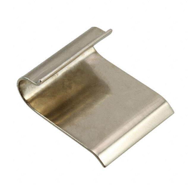
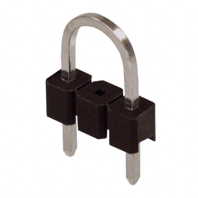
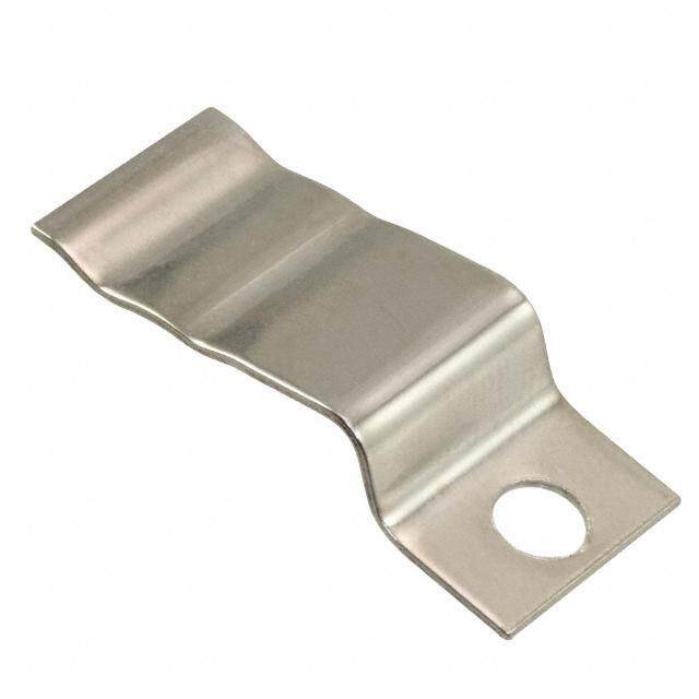
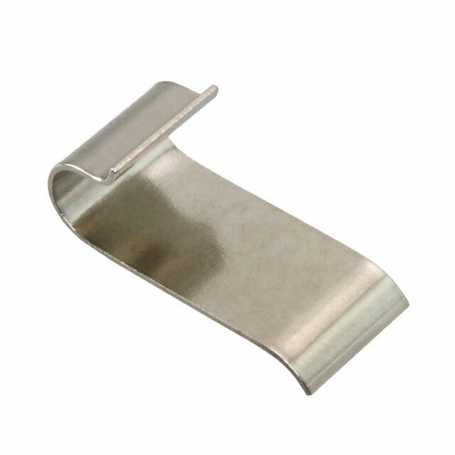
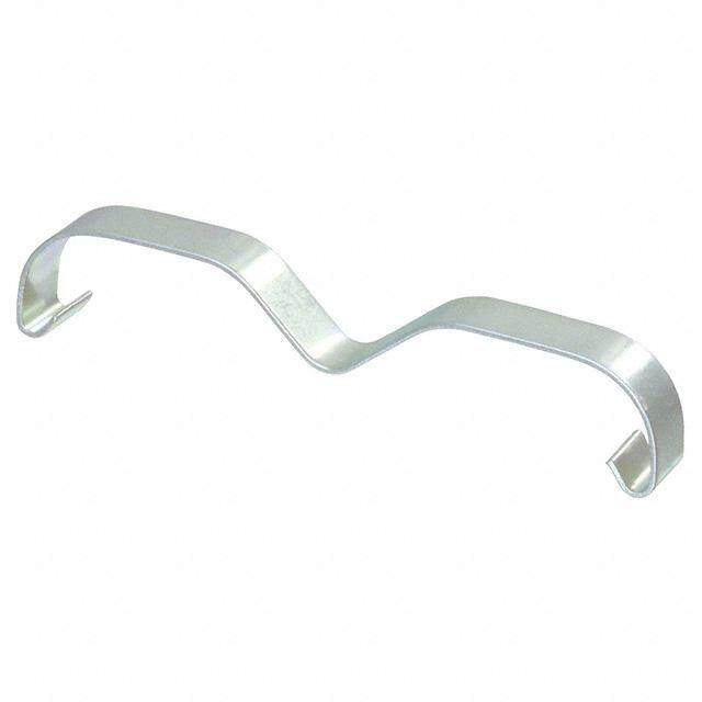
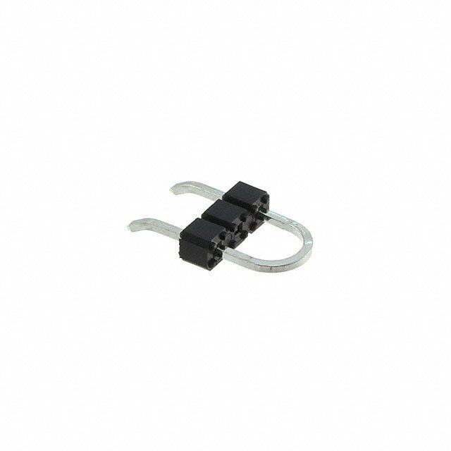
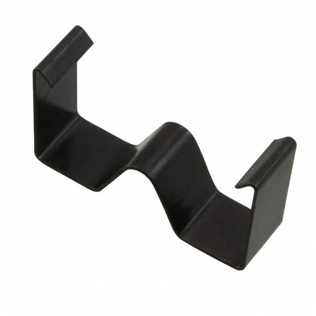
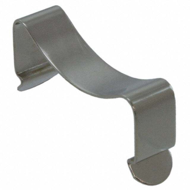
BGA–Solder Anchor Solder anchor attachment Aavid's unique Solder anchor attachment method uses two or four small Solder anchors attached to the circuit card and a wire spring clip to securely fasten the heat sink to the device.This method is S rugged,compact and allows for easy removal in E case of rework. G All products include a phase change pad suitable A K for most IC package styles to optimize thermal C performance.Models are available with a single A P or dual spring clips for additional thermal interface C pressure.Solder anchors are ordered separately. I R O F S K N I S T A E H ORDERINGINFORMATION IC Pkg Size (mm) IC Pkg Style Part Number “W”(mm) “L”(mm) “H”(mm) “A”(mm) θn1 θf2 Finish Fig.4 PCB Fig.4 #Anchors3 23 x 23 All 374024B60023G 23.00 23.00 10.00 49.70 40.00 11.69 Black anodize 1 A 2 23 x 23 All 374124B60023G 23.00 23.00 18.00 49.70 23.40 7.39 Black anodize 1 A 2 23 x 23 All 374224B60023G 23.00 23.00 25.00 49.70 19.70 6.37 Black anodize 1 A 2 27 x 27 All 374324B60023G 27.00 27.00 10.00 49.70 30.60 9.35 Black anodize 1 A 2 27 x 27 All 374424B60023G 27.00 27.00 18.00 49.70 20.30 6.46 Black anodize 1 A 2 27 x 27 All 374524B60023G 27.00 27.00 25.00 49.70 16.50 5.47 Black anodize 1 A 2 35 x 35 Flip chip 10-5634-01G 31.00 34.90 23.00 11.50 4.20 Black anodize 2 C 2 35 x 35 Flip chip 10-THMA-01G 31.00 34.90 35.00 10.70 3.95 Black anodize 2 C 2 35 x 35 All 374624B60024G 35.00 35.00 10.00 62.30 23.40 7.55 Black anodize 1 B 2 35 x 35 All 374724B60024G 35.00 35.00 18.00 62.30 15.30 5.15 Black anodize 1 B 2 35 x 35 All 374824B60024G 35.00 35.00 25.00 62.30 12.00 4.27 Black anodize 1 B 2 37.5 x 37.5 Flip chip 10-BRD2-01G 35.70 37.30 23.00 11.50 4.20 Clear anodize 2 B 2 37.5 x 37.5 Flip chip 10-BRD1-01G 37.50 37.50 23.00 10.10 3.83 Black anodize 2 B 2 37.5 x 37.5 Flip chip 10-BRD1-03G 37.50 37.50 23.00 10.10 3.83 Black anodize 3 D 4 37.5 x 37.5 Flip chip 10-BRD1-04G 37.50 37.50 23.00 10.10 3.83 Black anodize 2 B 2 37.5 x 37.5 Flip chip 10-BRD1-05G 37.50 37.50 23.00 10.10 3.83 Clear anodize 3 D 4 37.5 x 37.5 Flip chip 10-BRD1-07G 37.50 37.50 23.00 10.10 3.83 Clear anodize 2 B 2 40 x 40 All 374924B60024G 40.00 40.00 10.00 62.30 20.30 6.46 Black anodize 1 B 2 40 x 40 All 375024B60024G 40.00 40.00 18.00 62.30 12.20 4.34 Black anodize 1 B 2 42 x 40 All 375124B60024G 40.00 40.00 25.00 62.30 10.30 3.83 Black anodize 1 B 2 42.5 x 42.5 Flip chip 10-CLS1-01G 42.30 42.30 23.00 8.80 3.51 Black anodize 2 E 2 42.5 x 42.5 Flip chip 10-CLS2-01G 42.30 42.30 35.00 8.30 3.44 Black anodize 2 E 2 SOLDER ANCHOR 2.49 Part Number PCB Thickness (mm) “A”Dim (mm) 7.19 (0.098) (0.283) 125700D00000G 1.60 3.61 125800D00000G 2.54-2.79 4.70 "A" 0.64 (0.025) 5.08 (0.200) 7.62 (0.300) 1.Natural convection thermal resistance based on a 75º C heat sink temperature rise. 2.Force convection thermal resistance based on an entering 1.0 m/s (200LFM) airflow. 3.Solder anchors are sold separately refer to drawing above. 4.Solder anchor mechanical drawings and board mounting drawings see page 13. 12 sales.na@aavid.com www.shopaavid.com
BGA–Solder Anchor Solder anchor heat sinks mechanical drawings FIGURE 1 FIGURE 2 12.70 (0.500) "H" S "W" "L" 54.74 12.70 E (2.155) "W" (0.500) G A K C A "A" P C "L" "H" I R O F S K N I S T A FIGURE 3 E H (415.8.8086)"W" (105.5.0901) 15.00 (0.591) "H" "L" Board mounting pattern information for solder anchor heat sinks FIGURE A FIGURE B 35.56 48.26 (1.400) (1.900) ø0.97 ± 0.03 (0.038 ± 0.001) 26.67 (Ø0.00.3987 00..00031) PLATHEODL TEHS R4O XUGH (1.050) (25.31.0304) PLATHEOD LTEHSR 4OXUGH (26.66.0004) 33.02 (1.300) (107.7.7080) (05.2.0080)2X (02.49.5103) 5.08 (0.200)2x FIGURE C FIGURE D FIGURE E Ø 0.97 ± 0.03 45.72 PL(0A.0T3E8D ±T H0.R0O01U)GH (25.52.0808) (1.800) HOLES 2X Ø 0.97 0.03 (0.038 0.001) 48.26 Ø0.97 0.03 PLATED THROUGH (1.900) 2X (0.038 0.001) HOLES 4X 58.42 (02.49.5103) PLATHEODL TEHS R4OXUGH 66.04 (2.300) (2.600) 29.21 33.02 (1.150) (05.2.0080) 4X (1.300) 33.02 22.86 (1.300) (0.900) (05..20080)2X 66.04 (12.71.0904) 5.08 (2.600) 2X (0.200) 2X 13 sales.na@aavid.com www.shopaavid.com
BGA–Push Pin Attachment Push pin attachment Push pin heat sinks require two 3.10mm holes in the circuit card to quickly attach the heat sink over the device.The one piece design makes assembly a snap.Pressure is maintained by the tension of the push pin coil springs to ensure even pressure S E across the device.Push pins provide a greater margin of reliabil- G ity in applications where gravity or vibration may cause tapes or A adhesives to fail.The addition of a phase change pad optimizes K C thermal performance. A P C I R O F S K N I S T A E H ORDERINGINFORMATION IC Pkg.Size (mm) Part Number “W”(mm) “L”(mm) “H”(mm) “S”(mm) “T”(mm) θn2 θf3 Finish Fig. PCB Fig.1 Pin Style Pad 28 x 28 10-6326-27G 28.00 28.00 6.00 46.60 6.50 44.10 13.13 Black anodize 1 A Plastic Yes 28 x 28 10-6326-28G 28.00 28.00 6.00 46.60 6.50 44.10 13.13 Black anodize 1 A Brass Yes 28 x 28 10-6327-01G 28.50 28.50 10.00 46.60 7.00 30.60 9.26 Black anodize 2 A Plastic No 35 x 35 10-TNT2-01G 36.10 48.00 11.60 6.50 18.80 6.13 Black anodize 3 D Plastic No 37.5 x 37.5 10-5597-02G 37.40 37.40 6.00 59.00 6.50 33.30 9.91 Green anodize 5 B Plastic No 37.5 x 37.5 10-5597-22G 37.40 37.40 6.00 59.00 6.50 33.30 9.91 Gold anodize 5 B Plastic Yes 37.5 x 37.5 10-5597-33G 37.40 37.40 6.00 59.00 6.50 33.30 9.91 Gold anodize 5 B Brass Yes 37.5 x 37.5 10-5607-04G 37.40 37.40 10.00 59.00 7.00 22.10 6.99 Black anodize 5 B Plastic Yes 37.5 x 37.5 10-5607-05G 37.40 37.40 10.00 59.00 7.00 22.10 6.99 Black anodize 5 B Brass Yes 37.5 x 37.5 372924M02000G 37.40 37.40 6.00 59.00 6.50 32.60 9.91 Green anodize 5 B Plastic No 45 x 45 10-L4LB-03G 45.20 41.40 11.89 58.80 8.00 16.70 5.60 Black anodize 4 C Plastic Yes 45 x 45 10-L4LB-05G 45.20 41.40 11.89 58.80 8.00 16.70 5.60 Black anodize 4 C Brass Yes 45 x 45 10-L4LB-11G 45.20 41.40 11.70 58.80 8.00 14.20 4.91 Black anodize 4 C Plastic No 1.Push pin mechanical drawings and board mounting drawings see page 15 2.Natural convection thermal resistance based on a 75°C heat sink temperature rise. 3.Forced convection thermal resistance based on an entering 1.0 m/s (200LFM) airflow. 14 sales.na@aavid.com www.shopaavid.com
BGA–Push Pin Attachment Mechanical drawings FIGURE 1 FIGURE 2 FIGURE 3 41.70 "T" "H" "T" (416.8.6305) "H" (1.642) S "S" E G A "L" "L" "L" (411.6.5304) CK A P C I "W" "W" R "T" "W" "H" O F S K N I FIGURE 4 FIGURE 5 S T A "T" E "S" "H" H "S" "L" 20.02 "L" (0.788) "T" "W" 10.69 (0.421) "W" "H" Board mounting pattern information FIGURE A FIGURE B ø3.10 ± 0.030 (0.122 ± 0.001) THROUGH HOLES (UNPLATED) 2X 46.60 (1.830) REF 59.00 (2.320) REF 32.95 (1.297) Ø 3.10 0.03 41.74 (0.122 0.001) (1.643) THROUGH HOLES 16.48 16.48 (UNPLATED) 2X (02.08.2827) (0.649) (0.649) 32.95 20.87 (1.297) (0.822) 41.74 (1.643) FIGURE C FIGURE D Ø 3.10 ± 0.03 (Ø 0.122 ± 0.001) Ø 3.10 ± 0.03 THROUGH HOLES (Ø 0.122 ± 0.001) 20.02 (UNPLATED)2X THROUGH HOLES (0.788) (UNPLATED) 2X 41.50 (1.634) 20.85 (0.821) 10.01 25.40 20.75 (0.394) (1.000) (0.817) 41.70 50.80 (1.642) (2.000) 15 sales.na@aavid.com www.shopaavid.com
BGA–Tape Attachment Heat sinks for plastic BGA packages S E G A "L" "H" K C A P C I R O F S "W" K N SI Pressure sensitive,thermally conductive adhesive tape T easily and reliably bonds a heat sink to an integrated A circuit package.Tapes provide high thermal conductiv- E H ity and exceptional bonding properties.Adhesives are formulated for plastic and metal/ceramic packages. Material:Aluminum ORDERINGINFORMATION IC Pkg.Size (mm) IC Pkg.Style Part Number “W”(mm) “L”(mm) “H”(mm) θn2 θf3 Finish Tape code1 10 x 10 Plastic 375324B00035G 10.20 10.20 10.20 71.40 21.20 Black anodize 35 15 x 15 Plastic 375424B00034G 15.20 15.20 6.40 62.50 17.60 Black anodize 34 23 x 23 Plastic 374024B00035G 23.00 23.00 10.00 40.00 11.69 Black anodize 35 23 x 23 Plastic 374124B00035G 23.00 23.00 18.00 23.40 7.39 Black anodize 35 23 x 23 Plastic 374224B00035G 23.00 23.00 25.00 19.70 6.370 Black anodize 35 25 x 25 Plastic 335224B00034G 25.00 25.00 9.90 34.00 10.39 Black anodize 34 27 x 27 Plastic 374324B00035G 27.00 27.00 10.00 30.60 9.35 Black anodize 35 27 x 27 Plastic 374424B00035G 27.00 27.00 18.00 20.30 6.46 Black anodize 35 27 x 27 Plastic 374524B00035G 27.00 27.00 25.00 16.50 5.47 Black anodize 35 28 x 28 Plastic 373024B00034G 27.90 27.90 8.90 33.30 10.00 Black anodize 34 28 x 28 Plastic 2327B-CP50G 27.90 28.10 15.20 23.40 7.43 Black anodize 34 31 x 31 Plastic 335824B00034G 30.00 30.00 9.40 29.40 9.11 Black anodize 34 35 x 35 Plastic 371824B00034G 35.00 35.00 7.00 31.90 9.67 Black anodize 34 35 x 35 Plastic 374624B00035G 35.00 35.00 10.00 23.40 7.55 Black anodize 35 35 x 35 Plastic 374724B00035G 35.00 35.00 18.00 15.30 5.15 Black anodize 35 35 x 35 Plastic 374824B00035G 35.00 35.00 25.00 12.00 4.27 Black anodize 35 35 x 35 Plastic 372024B00034G 35.00 35.00 27.90 11.90 4.28 Black anodize 34 40 x 40 Plastic 374924B00035G 40.00 40.00 10.00 20.30 6.46 Black anodize 35 40 x 40 Plastic 364424B00034G 40.10 40.00 11.40 18.40 6.02 Black anodize 34 40 x 40 Plastic 375024B00035G 40.00 40.00 18.00 12.20 4.34 Black anodize 35 40 x 40 Plastic 375124B00035G 40.00 40.00 25.00 10.30 3.83 Black anodize 35 1.For tape specifications see page 88 2.Natural convection thermal resistance based on a 75°C heat sink temperature rise. 3.Forced convection thermal resistance based on an entering 1.0 m/s (200LFM) airflow. 16 sales.na@aavid.com www.shopaavid.com
BGA–Tape Attachment Heat sinks for metal/ceramic BGA packages S E G "L" "H" A K C A P C I R O F "W" S K N I S T A E H Material:Aluminum ORDERINGINFORMATION IC Pkg.Size (mm) IC Pkg.Style Part Number “W”(mm) “L”(mm) “H”(mm) θn2 θf3 Finish Tape Code1 10 x 10 Metal / Ceramic 375224B00032G 10.20 11.10 10.20 71.40 21.20 Black anodize 32 23 x 23 Metal / Ceramic 374024B00032G 23.00 23.00 10.00 40.00 11.69 Black anodize 32 23 x 23 Metal / Ceramic 374124B00032G 23.00 23.00 18.00 23.40 7.39 Black anodize 32 23 x 23 Metal / Ceramic 374224B00032G 23.00 23.00 25.00 19.70 6.370 Black anodize 32 25 x 25 Metal / Ceramic 335224B00032G 25.00 25.00 9.90 34.00 10.39 Black anodize 32 27 x 27 Metal / Ceramic 335324B00032G 26.90 26.90 11.40 27.70 8.71 Black anodize 32 27 x 27 Metal / Ceramic 374324B00032G 27.00 27.00 10.00 30.60 9.35 Black anodize 32 27 x 27 Metal / Ceramic 374424B00032G 27.00 27.00 18.00 20.30 6.46 Black anodize 32 27 x 27 Metal / Ceramic 374524B00032G 27.00 27.00 25.00 16.50 5.47 Black anodize 32 28 x 28 Metal / Ceramic 373024B00032G 27.90 27.90 8.89 33.30 10.00 Black anodize 32 28 x 28 Metal / Ceramic 373224M00032G 28.00 28.00 6.00 44.10 13.13 Green anodize 32 28 x 28 Metal / Ceramic 2327B-TACHG 27.90 28.10 15.20 23.40 7.43 Black anodize 32 31 x 31 Metal / Ceramic 335724B00032G 30.10 30.10 6.60 35.70 10.84 Black anodize 32 31 x 31 Metal / Ceramic 335824B00032G 30.00 30.00 9.40 29.40 9.11 Black anodize 32 32.5 x 32.5 Metal / Ceramic 2338B-TACHG 33.00 31.40 12.50 23.10 7.23 Black anodize 32 35 x 35 Metal / Ceramic 371824B00032G 35.00 35.00 7.00 31.90 9.67 Black anodize 32 35 x 35 Metal / Ceramic 374624B00032G 35.00 35.00 10.00 23.40 7.55 Black anodize 32 35 x 35 Metal / Ceramic 374724B00032G 35.00 35.00 18.00 15.30 5.15 Black anodize 32 35 x 35 Metal / Ceramic 374824B00032G 35.00 35.00 25.00 12.00 4.27 Black anodize 32 35 x 35 Metal / Ceramic 372024B00032G 35.00 35.00 27.90 11.90 4.28 Black anodize 32 37.5 x 37.5 Metal / Ceramic 373324M00032G 37.40 37.40 6.00 32.60 9.91 Green anodize 32 37.5 x 37.5 Metal / Ceramic 2319B-TACHG 38.10 38.10 10.16 12.50 3.50 Black anodize 32 37.5 x 37.5 Metal / Ceramic 336624B00032G 38.10 38.10 16.00 15.30 5.15 Black anodize 32 40 x 40 Metal / Ceramic 374924B00032G 40.00 40.00 10.00 20.30 6.46 Black anodize 32 40 x 40 Metal / Ceramic 364424B00032G 40.10 40.00 11.40 18.40 6.02 Black anodize 32 40 x 40 Metal / Ceramic 375024B00032G 40.00 40.00 18.00 12.20 4.34 Black anodize 32 40 x 40 Metal / Ceramic 375124B00032G 40.00 40.00 25.00 10.30 3.83 Black anodize 32 42.5 x 42.5 Metal / Ceramic 2321B-TACHG 43.20 41.30 8.90 22.10 6.93 Black anodize 32 42.5 x 42.5 Metal / Ceramic 2332B-TACHG 43.20 41.30 16.50 12.90 4.53 Black anodize 32 45 x 45 Metal / Ceramic 2342B-TACHG 45.70 44.60 7.00 23.10 7.26 Black anodize 32 50 + Metal / Ceramic 3334B-TACHG 50.50 50.20 16.50 6.0 3.3 Black anodize 32 1.For tape specifications see page 88 2.Natural convection thermal resistance based on a 75°C heat sink temperature rise. 3.Forced convection thermal resistance based on an entering 1.0 m/s (200LFM) airflow. 17 sales.na@aavid.com www.shopaavid.com
BGA–Clip Attachment Clip attachment S E G A K C A P C I R O F "L" "H" S K Aavid's BGS Clip heat sinks provide a mechanical N I attachment alternative to tape applications S where it is desirable to attach the heat sink T A directly to the device.The unique clip uses "W" E spring pressure to ensure even contact across H the device while the end plates firmly engage the edge of the package,locking the heat sink in place.Each heat sink uses pre-applied thermal grease for optimum thermal performance. Material: Aluminum Finish: Black Anodize ORDERINGINFORMATION IC Pkg.Size (mm) Part Number “W”(mm) “L”(mm) “H”(mm) IC Pkg.Style θn1 θf2 Interface Clip 27 x 27 2317B-EP11-BGS1G 26.14 20.47 15.24 All 32.60 9.94 EP11 BGS1 35 x 35 2518B-EP11-BGS2G 30.50 28.10 15.60 All 22.70 7.05 EP11 BGS2 42.5 x 42.5 2519B-EP11-BGS5G 34.50 31.40 15.60 All 19.70 6.30 EP11 BGS5 42.5 x 42.5 2520B-EP04-BGS5G 38.10 38.00 15.60 All 15.60 5.17 EP04 BGS5 42.5 x 42.5 2522B-EP04-BGS5G 38.10 38.00 10.16 All 22.10 6.94 EP04 BGS5 1.Natural convection thermal resistance based on a 75°C heat sink temperature rise. 2.Forced convection thermal resistance based on an entering 1.0 m/s (200LFM) airflow. THERMALCOTETM GREASE "E" PULL TAB "D" TAPE TYPE AND INTERFACE MATERIAL INFORMATION Material Description Adhesive Thermal Resistance Color Carrier “D”Dim “E”Dim EP11 ThermalcoteTMgrease with release liner None 0.18 White None 13.34 (0.525) 13.34 (0.525) EP04 ThermalcoteTMgrease with release liner None 0.03 White None 31.75 (1.250) 31.75 (1.250) For more information on ThermalcoteTMsee page 113. 18 sales.na@aavid.com www.shopaavid.com
BGA – Bi Directional Bi Directional S E G A "W" K C A P C I R O "L" "H" F S K Designed for applications with airflow traveling N I in a single direction,these heat sinks are suitable S for a variety of standard square IC packages. Material: Aluminum T A Models are available with pre-applied thermal E tape for easy attachment to the IC.Epoxy attach H models are also available. ORDERINGINFORMATION IC Pkg Size IC Pkg Style Part Number “W”(mm) “L”(mm) “H”(mm) θn3 θf4 Finish Attachment Tape Code 2 10 X 10 All 615653B00250G 6.00 6.00 5.00 142.58 76.26 Black anodize Epoxy1 N/A 10 X 10 All 709203B00400G 10.00 10.00 10.00 55.98 29.94 Black anodize Epoxy1 N/A 24 X 24 Metal 335114B00032G 24.00 24.00 24.00 13.60 7.27 Black anodize Tape 32 25 X 25 Metal 335214B00032G 25.00 25.00 10.00 10.00 5.35 Black anodize Tape 32 25 X 25 Metal 335211B00032G 25.00 25.00 10.00 10.00 5.35 Black anodize Tape 32 25 X 25 All 335214B00000G 25.00 25.00 10.00 10.00 5.35 Black anodize Epoxy1 N/A 25 X 25 All 335211B00000G 25.00 25.00 10.00 10.00 5.35 Black anodize Epoxy1 N/A 25 X 25 Plastic 335214B00034G 25.00 25.00 10.00 10.00 5.35 Black anodize Tape 34 27 X 27 Plastic 335314B00035G 27.00 27.00 11.00 10.00 5.35 Black anodize Tape 35 27 X 27 Metal 335314B00032G 27.00 27.00 11.00 10.00 5.35 Black anodize Tape 32 27 X 27 All 335314B00000G 27.00 27.00 11.00 10.00 5.35 Black anodize Epoxy1 N/A 28 X 28 All 700353U01100G 28.00 28.00 9.00 18.49 9.89 Unfinished Epoxy1 N/A 30 X 30 All 335814B00000G 30.00 30.00 9.00 10.50 5.61 Black anodize Epoxy1 N/A 30 X 30 All 335714B00000G 30.00 30.00 7.00 15.20 8.13 Black anodize Epoxy1 N/A 30 X 30 Metal 335814B00032G 30.00 30.00 9.00 9.20 4.92 Black anodize Tape 32 30 X 30 Metal 335714B00032G 30.00 30.00 7.00 15.20 8.13 Black anodize Tape 32 37.5 X 37.5 All 799403B01500G 38.00 38.00 10.00 12.21 6.53 Black anodize Epoxy1 N/A 37.5 X 37.5 All 336314B00000G 36.00 36.00 17.00 11.00 5.88 Black anodize Epoxy1 N/A 1.Epoxy ordered separately for information on Epoxy see page 114,115. 2.For tape specifications see page 88. 3.Natural convection thermal resistance based on a 75°C heat sink temperature rise. 4.Forced convection thermal resistance based on an entering 1.0 m/s (200LFM) airflow. 19 sales.na@aavid.com www.shopaavid.com
DIPS 5801 Slide on heat sink with staggered fins S E G A Air Velocity—Feet Per Minute K 0 200 400 600 800 1000 C 100 20 DUCTORPA Saetaltisdailceyh .oTenhs etho he 8ea atp tsi nsini nDkkI wP f eiptaahtcu skrteaasgg edgso equrubeildcek fsliypn rasinngd Mounting Surface TempRise Above Ambient—C°824600000 1108426Thermal Resistance From MTGSurface to Ambient—C/Watt° (104.5.2672) (105.6.2040) N action and locking catch to firmly attach 0 0.4 0.8 1.2 1.6 2.0 O Heat Dissipated—Watts the device creating a thermal conduction MIC pAavathil aobnl eb iont htw thoe f itnoisph aens.d bottom surfaces. (101.4.4530) E LOCKING S CATCH TE ORDERINGINFORMATION 10.54 (05.2.3130) RE Part Number Finish (0.415) (06.2.3550) C 580100B00000G Black anodize S 580100W00000G Black anodize with black paint on bottom side Material:0.63 (0.025) Thick Aluminum I Finish:See Table D LE 5010 Angle fin heat sink GEpreo&axsye O page112 H U R Air Velocity—Feet Per Minute H 0 200 400 600 800 1000 T 100 100 AcSounsigtta lsbeo lfelui nftoi ohr ne1 a4fot ars nicndok o1li6isn pag i snDi mpIPap dcleke avlogicweess. Mounting Surface TempRise Above Ambient—C°824600000 642800000Thermal Resistance From MTGSurface to Ambient—C/Watt° (109.7.0550) and available in two finish options. 0 0.4 0.8 1.2 1.6 2.0 Easily attaches using thermal epoxy. Heat Dissipated—Watts (105.6.3044) REF ORDERINGINFORMATION 5.39 (0.212) Part Number Finish 501000J00000G Pre black anodize* 6.35 (0.250) 501000B00000G Black anodize Material:1.27 (0.050) Thick Aluminum Finish:See Table * Edges cut during the manufacturing process will be unfinished. See page 110 for more information. 5602,5802 Slide on heat sink with angled fins Air Velocity—Feet Per Minute 0 200 400 600 800 1000 100 20 Saqtlutidiaccekh loye nsa nthode 1ae4ta ssaiinlnyd.kT 1wh6ei t phhien aa Dnt gIsPiln epkda fcfeikanatsgueress Mounting Surface TempRise Above Ambient—C°824600000 1108426Thermal Resistance From MTGSurface to Ambient—C/Watt° (202.8.6910) (105.6.2040) 0 0.4 0.8 1.2 1.6 2.0 double spring action and locking catch Heat Dissipated—Watts to firmly attach the device creating a 10.42 thermal conduction path on both the (0.410) top and bottom surfaces.Available in LOCKING two finishes. CATCH 5.08 21.34 (0.200) (0.840) "A" ORDERINGINFORMATION Part Number Device Pkg Style Finish “A”Dim 560200B00000G Ceramic Black anodize 7.87 (0.310) Material:0.63 (0.025) Thick Aluminum 560200W00000G Ceramic Black anodize with black paint on bottom side 7.87 (0.310) Finish:See Table 580200B00000G Plastic Black anodize 6.35 (0.250) 580200W00000G Plastic Black anodize with black paint on bottom side 6.35 (0.250) 20 sales.na@aavid.com www.shopaavid.com
DIPS 5806 Slide on heat sink with staggered fins S E G A Air Velocity—Feet Per Minute K 0 200 400 600 800 1000 C 100 10 A Mounting Surface TempRise Above Ambient—C°824600000 06428 Thermal Resistance From MTGSurface to Ambient—C/Watt° (412.6.6870) (12.50.0400) NDUCTORP Slide on heat sink with staggered fins 0 0.4 0.8 1.2 1.6 2.0 14.86 O attaches to 28 pin DIP packages quickly Heat Dissipated—Watts (0.585) C and easily.The heat sink features double I M sapttrainchg tahceti odne vainced clorecaktiningg c aa ttchhe rtmo afilr mly (317.4.4775) (102.5.7000) E LOCKING S conduction path on both the top and CATCH 13.72 E bottom surfaces. (0.540) T E R ORDERINGINFORMATION Material: 0.81 (0.032) Thick Aluminum C Finish: Black Anodize S I Part Number Description D 580600B00000G Slide on heat sink with staggered fins E L O H U R H T 5803 Slide on heat sink with staggered fins 28.58 Air Velocity—Feet Per Minute (1.125) 0 200 400 600 800 1000 100 20 Mounting Surface TempRise Above Ambient—C°824600000 1108426Thermal Resistance From MTGSurface to Ambient—C/Watt° (203.9.6320) 17.78 0 0.4 0.8 1.2 1.6 2.0 (0.700) Slide on heat sink with staggered fins Heat Dissipated—Watts attaches to 18 pin DIP packages quickly and easily.The heat sink features double 14.12 spring action and locking catch to firmly (0.556) attach the device creating a thermal conduction path on both the top and 5.33 (0.210) bottom surfaces. LOCKING CATCH 6.35 (0.250) ORDERINGINFORMATION Material: 0.63 (0.025) Thick Aluminum Part Number Description Finish: Black Anodize 580300B00000G Slide on heat sink with staggered fins 21 sales.na@aavid.com www.shopaavid.com
DIPS 5804 Slide on heat sink with staggered fins S E G A K Air Velocity—Feet Per Minute 28.58 (1.125) C 0 200 400 600 800 1000 A 100 20 NDUCTORP Mounting Surface TempRise Above Ambient—C°824600000 1108426Thermal Resistance From MTGSurface to Ambient—C/Watt° (216.0.8505) (107.7.7080) Slide on heat sink with staggered fins 0 0.4 0.8 1.2 1.6 2.0 O C attaches to 20 pin DIP packages quickly Heat Dissipated—Watts 14.12 I and easily.The heat sink features double (0.556) M spring action and locking catch to firmly SE attach the device creating a thermal LOCKING CATCH (05.2.3130) conduction path on both the top and 6.35 TE bottom surfaces. (0.250) E R Material: 0.63 (0.025) Thick Aluminum C ORDERINGINFORMATION Finish: Black Anodize S Part Number Description I D 580400B00000G Slide on heat sink with staggered fins E L O H U R H T 5805 Slide on heat sink with staggered fins Air Velocity—Feet Per Minute 0 200 400 600 800 1000 100 10 Mounting Surface TempRise Above Ambient—C°824600000 06428 Thermal Resistance From MTGSurface to Ambient—C/Watt° 37.08 0 0.4 0.8 1.2 1.6 2.0 (1.460) 25.60 Slide on heat sink with staggered fins Heat Dissipated—Watts (1.008) attaches to 24 pin DIP packages quickly and easily.The heat sink features double 14.73 spring action and locking catch to firmly (0.580) attach the device creating a thermal conduction path on both the top and LOCKING bottom surfaces. CATCH 32.51 12.19 (1.280) (0.480) 13.72 (0.540) ORDERINGINFORMATION Part Number Description Material: 0.81 (0.032) Thick Aluminum Finish: Black Anodize 580500B00000G Slide on heat sink with staggered fins 22 sales.na@aavid.com www.shopaavid.com
DIPS Grease 5085,5086,5087 Extruded epoxy attach on heat sink with straight fins Epo&xy page112 S E G Air Velocity—Feet Per Minute A 0 200 400 600 800 1000 K 100 20 C Ewxitthru sdtreadig ehpt ofixnys aattttaacchhe os nto h 2e4a,t2 s8i,nk Mounting Surface TempRise Above Ambient—°C8246000000 1 2 3 4 511 08426Thermal Resistance From MTGSurface to Ambient—°C/Watt "A" 4.83 (103.5.4360) DUCTORPA (0.190) N and 40 pin DIP packages quickly and 508700 Heat Dissipated—Watts easily.May be added before or after 508600 O 508500 C final board assembly.No additional Material: Aluminum I board space is required. Finish: Black Anodize M E S ORDERINGINFORMATION E T Part Number DIP Package “A”Dim E R 508500B00000G 24 pin 31.75 (1.250) C 508600B00000G 28 pin 36.83 (1.450) S I 508700B00000G 40 pin 50.80 (2.000) D For epoxy information see pages 114-115. E L Grease O 6284 Extruded epoxy attach heat sink Epo&xy H page112 U R H Air Velocity—Feet Per Minute 12.06 T 0 200 400 600 800 1000 (0.475) 100 25 REF Ewxhtircuhd reedq ueipreosx nyo a attdadcihti ohneaal tb soinarkd Mounting Surface TempRise Above Ambient—°C824600000 11205500Thermal Resistance From MTGSurface to Ambient—°C/Watt (316.4.8530)REF space is suitable for narrow DIP 0 1 2 3 4 5 packages.May be added before Heat Dissipated—Watts or after final board assembly.No additional board space is required. Attaches to 28 pin DIP. 13.46 (0.530) ORDERINGINFORMATION Material: Aluminum Part Number Description Finish: Black Anodize 6284BG Extruded epoxy attach heat sink for 28 pin DIP For epoxy information see pages 114-115. Grease 5011,5012 Extruded epoxy attach heat sink with straight fins Epo&xy page112 FIGURE A FIGURE B 4.83 (0.190) 6.35REF (0.250) 19.05 4.82REF 18.57 6.35 (0.750) (0.190) (0.730) (0.250) Material: Aluminum Finish: Black Anodize Extruded epoxy attach heat sink with straight fins attaches to 14 and 16 pin Air Velocity—Feet Per Minute DIP packages quickly and easily.May be 0 200 400 600 800 1000 added before or after final board assembly. 100 100 PONAavoRrat D aiNldaEubdmRliIbetNei oriGnn atINwl bFoDoO feaiRsnrcdM rdi psAitrpiTeoaIcncOteiNo ins sr.equired. Figure Mounting Surface TempRise Above Ambient—°C824600000 5011–5012 642800000Thermal Resistance From MTGSurface to Ambient—°C/Watt 501100B00000G Extruded epoxy attach heat sink with straight fins A 0.0 0.4 0.8 1.2 1.6 2.0 501200B00000G Extruded epoxy attach heat sink with straight fins B 501100 Heat Dissipated—Watts For epoxy information see pages 114-115. 501200 23 sales.na@aavid.com www.shopaavid.com
SMT 5731 Surface mount heat sink for D-PAK (TO-252) package semiconductors S E G A Air Velocity—Feet Per Minute K 0 200 400 600 800 1000 C 100 25 8.00 DUCTORPA S(reTumOrf-oa2vc5ee2 t)mh peoa hucenkata tgh iene adstier semicnitcklyo fnwodrit uhDco-tPuoAtrKs Case Temp RiseRise Above Ambient—°C824600000 11205500Thermal Resistance From MTGSurface to Ambient—°C/Watt ((1000..43.101605)) (202.9.8060) 8.13 N contacting the device like traditional 0.0 0.5 1.0 1.5 2.0 2.5 (0.320) O through hole heat sinks.The device Heat Dissipated—Watts C and the heat sink are soldered directly (01.0.35) (100.4.4110) I to a modified drain pad creating a M Material: 0.63 (0.025) Thick Copper E thermal transfer path from package Finish: Tin Plated S tab to the heat sink. Refer to Figure A and B on page 26 for board footprint information E ORDERINGINFORMATION T E Part Number Packaging R C 573100D00010G 13" Reel,250 per reel S 573100D00000G Bulk,500 per bag I D See page 25 for tape and reel information E L 5733 Surface mount heat sink for D2PAK (TO-263) package semiconductors O H U R Air Velocity—Feet Per Minute H 0 200 400 600 800 1000 12.70 T S(reTumOrf-oa2vc6ee3 t)mh peoa hucenkata tgh iene adstier semicnitcklyo fnwodrit uhDco2t uPoAtrsK Case Temp RiseRise Above Ambient—°C54123000000 211060842 Thermal Resistance From MTGSurface to Ambient—°C/Watt ((010.0.54.010060)) (216.0.1360) (07.2.3970) 0.0 0.5 1.0 1.5 2.0 2.5 contacting the device like traditional Heat Dissipated—Watts 1.3 12.70 through hole heat sinks.The device (0.05) (0.500) and the heat sink are soldered directly Material: 0.63 (0.025) Thick Copper to a modified drain pad creating a Finish: Tin Plated thermal transfer path from package tab to the heat sink. Refer to Figure A and B on page 26 for board footprint information ORDERINGINFORMATION Part Number Packaging 573300D00010G 13" Reel,250 per reel 573300D00000G Bulk,500 per bag See page 25 for tape and reel information 7106 Surface mount heat sink for D2 PAK (TO-263),power SO-10 (MO-184) and SO-10 package semiconductors 5.33 Air Velocity—Feet Per Minute (0.210) 0 200 400 600 800 1000 100 10 S(areTnumOdrf-o a2Svc6Oee3 - t1)mh,0epo pohuawencatek trh ai neSgaOdeti -r s1seei0cnmt (klyMi c fwooOnri-t 1dhD8ou2 4uPc)tAtoKrs Mounting Surface TempRise Above Ambient—°C824600000 06428 Thermal Resistance From MTGSurface to Ambient—°C/Watt (104.5.9990) (12105.0..192610) (100.4.9320) (104.5.9990) 0 1 2 3 4 5 (0.400) contacting the device like traditional Heat Dissipated—Watts through hole heat sinks.The device 9.52 and the heat sink are soldered directly (0.375) to a modified drain pad creating a 7.62 (0.300) thermal transfer path from package tab to the heat sink. Material: 0.63 (0.025) Thick Copper Finish: Tin Plated ORDERINGINFORMATION Part Number Packaging Refer to Figure C on page 26 for board footprint information 7106D/TRG 13" Reel,200 per reel 7106DG Bulk,500 per bag See page 25 for tape and reel information 24 sales.na@aavid.com www.shopaavid.com
SMT 7109 Surface mount heat sink for D2 PAK (TO-263) package semiconductors S E G A Air Velocity—Feet Per Minute K 0 200 400 600 800 1000 19.38 C S(rceToumOnrft-oaa2vcc6ete3i nt)mh gpeo at huhceneka tad tgh eienev aidsctieer sem licinkitceklyo t fnwroadridt uhDitcoi2to uPonAtrasKl Mounting Surface TempRise Above Ambient—°C1082460000000 1 2 3 4 5503214 Thermal Resistance From MTGSurface to Ambient—°C/Watt ((121055..06..24004000)) (0.763) NDUCTORPA through hole heat sinks.The device Heat Dissipated—Watts 11.43 O and the heat sink are soldered directly (0.450) C to a modified drain pad creating a 11.43 MI thermal transfer path from package (0.450) E tab to the heat sink. S ORDERINGINFORMATION Refer to Figure D on page 26 for board footprint information E T Part Number Packaging E Material: 0.63 (0.025) Thick Copper R 7109D/TRG 13" Reel,125 per reel Finish: Tin Plated C 7109DG Bulk,500 per bag S See below for tape and reel information DI E 5734 Surface mount heat sink for D3 PAK (TO-268) package semiconductors L O H U R Air Velocity—Feet Per Minute H 0 200 400 600 800 1000 T 50 20 12.70 S(rceToumOnrft-oaa2vcc6ete8i nt)mh gpeo at huhceneka tad tgh eienev aidsctieer sem licinkitceklyo t fnwroadridt uhDitcoi3to uPonAtrasKl Case Temp RiseRise Above Ambient—°C412300000 1160842 Thermal Resistance From MTGSurface to Ambient—°C/Watt ((010.0.54.010060)) (310.2.9290) 7.37 through hole heat sinks.The device 0.0 0.5 1.0 1.5 2.0 2.5 (0.290) and the heat sink are soldered directly Heat Dissipated—Watts 1.3 17.53 to a modified drain pad creating a (0.05) (0.690) thermal transfer path from package Refer to Figure A and B on page 26 for board footprint information tab to the heat sink. ORDERINGINFORMATION Material: 0.63 (0.025) Thick Copper Finish: Tin Plated Part Number Packaging 573400D00010G 13" Reel,250 per reel 573400D00000G Bulk,500 per bag See below for tape and reel information Tape and Reel information D B C A ORDERINGINFORMATION Part Number “A”Dim “B”Dim “C”Dim “D”Dim 7106D/TRG 44.00 (1.730) 40.40 (1.590) 24.00 (0.940) 4.06 (0.160) 7109D/TRG 44.00 (1.730) 40.40 (1.590) 36.00 (1.420) 4.06 (0.160) 573100D00010G 44.00 (1.730) 40.40 (1.590) 16.00 (0.630) 4.06 (0.160) 573300D00010G 44.00 (1.730) 40.40 (1.590) 24.00 (0.940) 4.06 (0.160) 573400D00010G 44.00 (1.730) 40.40 (1.590) 24.00 (0.940) 4.06 (0.160) 25 sales.na@aavid.com www.shopaavid.com
SMT Footprints S E FIGURE A FIGURE B G Recommended copper heat speader drain pad footprint Recommended heat sink solder mask opening A K C A P OR W W1 T Note:The thickness of W2 C the drain pad is variable U D depending on the amount L N of heat generated by the L O SMT device,design limita- C tions and process. 0.80 1.40 I (0.030) (0.060) M E S E T E R Part Number “L” “W” Part Number “L” “W1” “W2” C S 573100 9.53 (0.375) 13.97 (0.550) 573100 9.02 (0.355) 13.46 (0.530) 8.89 (0.350) I D 573300 14.22 (0.560) 16.26 (0.640) 573300 13.72 (0.540) 15.75 (0.620) 11.18 (0.440) E OL 573400 14.22 (0.560) 21.08 (0.830) 573400 13.72 (0.540) 20.57 (0.810) 16.00 (0.630) H U R H T FIGURE C FIGURE D Recommended copper pad size Recommended copper pad size for heat sink and device mounting footprint for heat sink and device mounting footprint 10.41 (0.410) 20.32 15.49 (0.800) 2.29 (0.610) 2.54 (0.090) (0.100) 10.67 (0.420) 15.49 2.54 (0.610) 7.62 10.67 (0.100) (0.300) (0.420) 16.76 (0.660) For D Pak (TO-263) For MO-184 and SO-10 26 sales.na@aavid.com www.shopaavid.com
TO-220 Heat Sinks Grease Mounting 7025 Channel style heat sink with folded back fins Epo&xy Kits page112 page 99 S E G Air Velocity—Feet Per Minute ø3.81THRU A 0 200 400 600 800 1000 (0.150) K Cbarhaecaakn. Anfivenalsi sl aftobyrll eein whcreiteahat st seinidn pkclo awoteiltidnh gs fo oslulddreferad-ce Mounting Surface TempRise Above Ambient—C°1082460000000 2 4 6 8 10503214 Thermal Resistance From MTGSurface to Ambient—C/Watt° (12.81.3700)(203.(90.263.0.2008)20) (42188.1.2.00634) TAB(104.5.4780)(05.(2.0020.81.050)40) (109.7.0550) (((00203.4.0..1.21.19429780555))) DUCTORPAC able tabs for easy attachment to the Heat Dissipated—Watts (1.900) N printed circuit card. O 26.67 C (1.050) I ORDERINGINFORMATION Dia of PCB 24.13 M Plated Thru (0.950) E Part Number Description Hole for Tabs S 7025BG Channel heat sink with no solderable tabs Material:1.27 (0.050) Thick Aluminum E Finish:Black Anodize T 7025B-MTG With solderable mounting tabs 2.90 ( 0.114) E For additional options see page 85 R Grease Mounting C 7019 Narrow channel style heat sink with folded back fins Epo&xy Kits S page112 page 99 DI E L Air Velocity—Feet Per Minute 11.94 O 0 200 400 600 800 1000 (0.470) ø3.81 H Nfsoualrdrfareocdew ba carhecaak.n Afnivneasli lsfaotbyrl leien wchrieethaast t eisndin pckola woteliitndhg Mounting Surface TempRise Above Ambient—C°1082460000000 2 4 6 8 101064280Thermal Resistance From MTGSurface to Ambient—C/Watt° (12.50.0400)(104.5.4T7A80B) (318.5.2035) ((T002H..10.0R583U00)) (05.2.008(00)4.(1.0839.31.012)85) THRU solderable tabs for easy attachment to Heat Dissipated—Watts 39.37 (1.550) the printed circuit card. 9.52 (0.375) ORDERINGINFORMATION Dia of PCB Plated Thru 2.28 Part Number Description Finish Hole for Tabs (0.090) Material:1.02 (0.040) Thick Aluminum 7019BG Channel heat sink with no solderable tabs Black anodize Finish:See Table 7019PBG Channel heat sink with no solderable tabs Pre black anodize* 7019B-MTG With solderable tabs Black anodize 2.90 ( 0.114) *Edges cut during the manufacturing process will be unfinished. See page 110 for more information For additional options see page 85 Grease Mounting 7020 Narrow channel style heat sink with folded back fins Epo&xy Kits page112 page 99 Air Velocity—Feet Per Minute 33.02 (1.300) 0 200 400 600 800 1000 100 10 Nfoaldrreodw b cahcakn fninesl sfotyr lien chreeaast esdin cko woliitnhg Mounting Surface TempRise Above Ambient—C°824600000 06428 Thermal Resistance From MTGSurface to Ambient—C/Watt° (316.4.8530(ø)03.1.8510)2x CL"x" (104.5.478(00)7.3.8170) (04..18930) 0 2 4 6 8 10 surface area.Available with tin plated Heat Dissipated—Watts sthoeld perrianbtleed t acibrcs ufoitr c eaarsdy. attachment to TAB 31.8(802.0.0820) (06.2.1400) (03.1.1285) (1.255) ORDERINGINFORMATION Dia of PCB 17.78 Plated Thru (0.700) Part Number Description Hole for Tabs 11.94 7020BG Narrow channel heat sink with no solderable tabs (0.470) Material:1.27 (0.050) Thick Aluminum Finish:Black Anodize 7020B-MTG With solderable tabs 2.90 (0.114) POPULAR OPTIONS: 7020B- G Base part no. A Position Code Description Location Details A TC10-MT Insulating device mounting clip Hole X Page 93,98 and solderable tabs For additional options see page 85 27 sales.na@aavid.com www.shopaavid.com
TO-220 Heat Sinks Grease Mounting 7021 Channel style heat sink with folded back fins Epo&xy Kits page112 page 99 S E G 44.45 A Air Velocity—Feet Per Minute (1.750) 2x ø3.81 (0.150) K 0 200 400 600 800 1000 DUCTORPAC Mounting Surface TempRise Above Ambient—C°108246000000 503214 Thermal Resistance From MTGSurface to Ambient—C/Watt° (316.4.8530) "X" (104.5.47(8007).3.8170) (04.(1.0839.31.012)85) ON Cfohladnende bl asctkyl fei nhsefaotr s iinnckre wasitehd 0 2 Heat4 Dissipated6—Watts8 10 TAB (02.0.0820) (02.1.6075) 5.58 C cooling surface area.Available 43.05 (0.220) (1.695) MI with tin plated solderable tabs E for easy attachment to the 17.78 S printed circuit card. 9.65 (0.700) E (0.380) T 2.28 E (0.090) R ORDERINGINFORMATION Dia of PCB Material:1.27 (0.050) Thick Aluminum C Plated Thru Finish:Black Anodize S Part Number Description Hole for Tabs I D 7021BG Channel heat sink with no solderable tabs E 7021B-MTG With solderable tabs 2.90 ( 0.114) L O H POPULAR OPTIONS: 7021B- G U R Base part no. A H Position Code Description Location Details T A TC10-MT Locking device mounting clip and solderable tabs Hole X Page 93,98 A MT5 Bifurcated tabs with 0.205 stand off Page 93 A MT6 Bifurcated tabs with 0.115 stand off Page 93 A TC10-MT5 Locking device mounting clip and bifurcated tabs Hole X Page 93,98 For additional options see page 85 Grease Mounting 7023 Channel style heat sink with folded back fins Epo&xy Kits page112 page 99 2x ø3.81THRU Air Velocity—Feet Per Minute (0.150) 0 200 400 600 800 1000 Mounting Surface TempRise Above Ambient—C°108246000000 503214 Thermal Resistance From MTGSurface to Ambient—C/Watt° (419.9.5530(()10105.4.65..41479080)) A "X" ((0025..1.2.50004800)) 19.05 (04..14755) 0 2 4 6 8 10 (0.750) Cfohladnende bl asctkyl fei nhsefaotr s iinnckre wasitehd Heat Dissipated—Watts TAB (12.81.0043) (04..18930) 2.2(903.1.1285) SECTION A-A cooling surface area.Available A (0.090) with tin plated solderable tabs for easy attachment to the 48.26 printed circuit card. (1.900) 26.67 (1.050) ORDERINGINFORMATION Dia of PCB Plated Thru 24.13 Part Number Description Hole for Tabs (0.950) 7023BG Channel heat sink with no solderable tabs 7023B-MTG With solderable tabs 2.90 ( 0.114) Material:1.27 (0.050) Thick Aluminum Finish:Black Anodize POPULAR OPTIONS: 7023B- G Base part no. A Position Code Description Location Details A TC6-MT Locking device mounting clip and solderable tabs Hole X Page 93,98 A TC7-MT Insulating device mounting clip and solderable tabs Hole X Page93,98 For additional options see page 85 28 sales.na@aavid.com www.shopaavid.com
TO-220 Heat Sinks Grease Mounting 7022 Channel style heat sink with folded back fins Epo&xy Kits page112 page 99 S E G Air Velocity—Feet Per Minute A 0 200 400 600 800 1000 9.52 23.01 K Mounting Surface TempRise Above Ambient—C°108246000000 503214 Thermal Resistance From MTGSurface to Ambient—C/Watt° (0.375)2xø(03.1.8510) ((5100..99.480"466X))" DUCTORPAC Channel style heat sink with 0 4 Heat D8issipated—12Watts 16 20 (201.8.0238) (419.9.9698) ON folded back finsfor increased 4.83 14.48 C cooling surface area.Available (0.190) 2(0x. 135.801) (0.570) MI with tin plated solderable tabs 2.02 E TAB (0.080) S for easy attachment to the 3.18 2.67 printed circuit card. 2.(209.125) (0.105) 2x(02.0.0830) TE (04.1.4745) (0.090) (204.9.1561) CRE OPaRrtD NEuRmIbNerGINDFeOscRriMptAioTnION Finish HPDolalieat e fodof r TP ThCarBbus MaFtienriisahl::1Se.2e7 T (a0b.0le50) Thick Aluminum DIS 7022BG Channel heat sink with no solderable tabs Black anodize E L 7022PBG Channel heat sink with no solderable tabs Pre black anodize* O 7022B-MTG With solderable tabs Black anodize 2.90 ( 0.114) H 7022PB-MTG With solderable tabs Pre black anodize* 2.90 ( 0.114) U R * Edges cut during the manufacturing process will be unfinished. See page 110 for more information H T POPULAR OPTIONS: 7022B- G Base part no. A Position Code Description Location Details A TC11-MT Insulated device mounting clip for T0-220 and solderable tabs Hole X Page 93,98 For additional options see page 85 Grease Mounting 5510 High performance channel style heat sink with folded back fins Epo&xy Kits page112 page 99 Air Velocity—Feet Per Minute ø 3.68THRU 0 200 400 600 800 1000 (0.145) High performance channel style Mounting Surface TempRise Above Ambient—C°108246000000 1064280Thermal Resistance From MTGSurface to Ambient—C/Watt° (215.0.5056)(10(2.051..703583.34)06) CL (01.35.(220901.3.)9910(1)03.5.4360) heat sink with folded back fins 0 1 2 3 4 5 Heat Dissipated—Watts for greater cooling capacity in a 19.99 minimum of space when mounted (0.787) horizontally.Folded back fin design 36.83 maximizes surface area without (1.450) increasing the vertical space required by the heat sink. Material:1.27 (0.050) Thick Aluminum Finish:Black Anodize ORDERINGINFORMATION Part Number Description 551002B00000G High performance channel style heat sink with folded back fins POPULAR OPTIONS: 551002B0 00 00G Base part no. A Position Code Description Details A 01 6-32 Wave On threaded insert Page 89 0.100 stand off For additional options see page 82 29 sales.na@aavid.com www.shopaavid.com
TO-220 Heat Sinks Grease Mounting 6021,6221 Channel style heat sink with straight fins Epo&xy Kits S page112 page 99 E FIGURE A FIGURE B G KA (12.50.0400) (03.1.8510) WIDE X (12.50.0400) AC (01..00420) ø(0 3.1.3383) (102.5.7000) (09.3.5725)LONG SLOT (01.0.0420) (102.5.7000) P R "X" O 29.97 29.97 T (1.180) 17.78 (1.180) 17.78 C (0.700) 3.81 (0.700) (0.150) U D (00.0.8302) 3.80 (00.0.8302) "B" ON (204.9.3680) "B""A" (0.150) (02.49.6589) "A" C Channel style heat sink with I Material:1.02 (0.040) Thick Aluminum M straight finsfeatures integrated Finish:See Table E solderable tabs for easy mounting Air Velocity—Feet Per Minute S to the printed circuit card.Available 100 0 200 400 600 800 100010 EDISCRETE wovari rtsyhloi natg tse idndeg hvleoic ldee e ltevoai cadec lcmeonomgutonhdtsai.ntge hole Mounting Surface TempRise Above Ambient—C°824600000 06428 Thermal Resistance From MTGSurface to Ambient—C/Watt° L 0 2 4 6 8 10 O Heat Dissipated—Watts H ORDERINGINFORMATION Dia of PCB U Plated Thru Part Number Description Finish Figure Hole for Tabs “A”Dim “B”Dim R H 6021BG Channel heat sink with straight fins and integrated tabs Black anodize A 2.21 (0.087) 10.16 (0.400) 1.78 (0.070) T 6021PBG Channel heat sink with straight fins and integrated tabs Pre-black anodize* A 2.21 (0.087) 10.16 (0.400) 1.78 (0.070) 6221PBG With slotted device mounting hole Pre-black anodize* B 3.18 (0.125) 6.99 (0.275) 2.54 (0.100) * Edges cut during the manufacturing process will be unfinished. See page 110 for more information POPULAR OPTIONS: 6021- - G Available on the 6021 only Base part no. A B Position Code Description Location Details A B Black anodize A PB Pre-black anodize* B SF1 4-40 UNC-2A device mounting stud Hole X Page 96 For additional options for part 6021 see page 85 Grease Mounting 6230 Copper channel style heat sink with straight fins Epo&xy Kits page112 page 99 3.81 Air Velocity—Feet Per Minute (0.150) 0 200 400 600 800 1000 100 10 Copper channel style heat sink Mounting Surface TempRise Above Ambient—C°824600000 06428 Thermal Resistance From MTGSurface to Ambient—C/Watt° (12.91.8907)(107.7.7080) (12.50.0400) (09.3.5735) (02.1.5040) 6.9(803.1.8510) 0 2 4 6 8 10 with straight finsfeatures integrated Heat Dissipated—Watts 12.70 (0.275) tabs which can be twisted to attach (0.500) the heat sink to the board prior to wave solder. Material:0.63 (0.025) Thick Copper Finish:Tin Plated ORDERINGINFORMATION Dia of PCB Plated Thru Part Number Description Hole for Tabs 6230DG Channel heat sink with straight fins and integrated tabs 3.00 (0.118) 30 sales.na@aavid.com www.shopaavid.com
TO-220 Heat Sinks Grease Mounting TV35 Narrow channel style heat sink features twisted fins Epo&xy Kits page112 page 99 S E G A Air Velocity—Feet Per Minute K 0 200 400 600 800 1000 2X4.00øTHRU C Mounting Surface TempRise Above Ambient—°C108246000000 1064280 Thermal Resistance From MTGSurface to Ambient—°C/Watt CL (0.158) DUCTORPA 0 2 4 6 8 10 N Heat Dissipated—Watts 10.00 14.00 O Narrow channel style heat sink (0.394) (0.552) C features twisted fins for increased MI air turbulence and better cooling. E Mounts horizontally to accommo- (412.6.0505) S date two TO-220 devices. E T E 25.00 R (0.985) C ORDERINGINFORMATION S I D Part Number Description 38.00 35.00 E TV35G Channel style heat sink with twisted fins (1.497) (1.380) L O Material: 0.81 (0.032) Thick Aluminum H Finish:Black Anodize U R H T Grease Mounting TV46,TV47,TV58 Narrow channel style heat sink features twisted fins Epo&xy Kits page112 page 99 Air Velocity —Feet Per Minute 0 200 400 600 800 1000 19.00 100 20 (0.749) Narrow channel style Mounting Surface TempRise Above Ambient—°C824600000 1108426Thermal Resistance From MTGSurface to Ambient—°C/Watt CL (04.1.0507ø)THRU heat sink features twisted 0 1 2 3 4 5 “B” 22.00 fins for increased air turbu- TV58 Heat Dissipated —Watts (0.887) lence and better cooling.Can be TV46, TV47 MAX mounted vertically or horizontally. "A" 11.00 (0.433) ORDERINGINFORMATION MIN Part Number “A”Dim “B”Dim TV46G 13.00 (0.512) 9.50 (0.374) Material: 0.81 (0.032) Thick Aluminum Finish:Black Anodize TV47G 13.00 (0.512) 6.30 (0.248) TV58G 11.00 (0.433) 6.30 (0.248) 31 sales.na@aavid.com www.shopaavid.com
TO-220 Heat Sinks Grease Mounting TV265,TV1500,TV1505 Channel style heat sink features twisted fins Epo&xy Kits page112 page 99 S E G Air Velocity—Feet Per Minute FIGURE A UCTORPACKA Mounting Surface TempRise Above Ambient—°C108246000000 0 200 400 600 800 1000211084026Thermal Resistance From MTGSurface to Ambient—°C/Watt (415.7.0702) (102.5.7000) R(01.0.9705) ((31200.2.C18L..08170100)) (05.2.0080) D 0 2 4 6 8 10 N TV1500 Heat Dissipated—Watts 15.24 O TV1505 (0.600) C MI 4.50 0.75 Air Velocity—Feet Per Minute (0.177) (0.030) SE 100 0 200 400 600 800 100020 (01.0.9705) 10.15 (215.0.4000) LEDISCRETE CtlmMtewwhnooiiacsdustneten e tnlatasdeen bad ldfs r is evnobte ysarer lvtmfteotaice orihalr auie lnclbnayocl tterooi ens lrwaii gnnhsi gteoksho.dr fC il iezdanaoaietnrnter utatbguabrerrleallbeystu.e td-abs. Mounting Surface TempRise Above Ambient—°C8246000000 1 2 3 4 51108426Thermal Resistance From MTGSurface to Ambient—°C/Watt F(I10G2.U5.70R00E) B (05.2.0(0080.4)00) (310.C1L.0801) R(01.0.9705) O TV 265 Heat Dissipated—Watts 30.20 H (1.187) RU ORDERINGINFORMATION PDlaiate odf TPhCrBu TVT1A5B05 (105.6.2040) H Part Number Description Figure Hole for Tabs ONLY T 1.20 3.80 TV265G Channel style heat sink with twisted fins and solderable tabs A 2.39 (0.094) 2.54 (0.047) (0.150) TV1500G Channel style heat sink with twisted fins B (0.100) 5.80 24.13 (0.228) (0.950) TV1505G With integrated twist tabs B 3.30 (0.130) Material:1.27 (0.050) Thick Aluminum Finish:Black Anodize Grease Mounting 5900 Channel style heat sink features solderable tabs and twisted fins Epo&xy Kits page112 page 99 Air Velocity—Feet Per Minute 0 200 400 600 800 1000 30.40 100 10 (1.197) Mounting Surface TempRise Above Ambient—C°824600000 06428 Thermal Resistance From MTGSurface to Ambient—C/Watt° (311.2.2208) (102.4.5902) (05.2.10011)5.20 (03.C1.L8510) clSiplo atst tfaocrh 0 2 4 6 8 10 5.00 (0.598) (0.197) Heat Dissipated—Watts 0.80 Channel style heat sink features (0.031) solderable tabs and twisted fins 11.10 (01.0.9705) (204.9.2503) for increased air turbulence for bet- (0.437) 25.00 ter cooling.For ease of assembly use (0.984) with clip 7701 (sold separately) to attach device.See page 97 for clip information. Material:1.19 (0.047) Thick Aluminum ORDERINGINFORMATION Dia of PCB Finish:Pre Black Anodize* Plated Thru Part Number Description Hole for Tabs 5900PBG Channel style heat sink with twisted fins and solderable tabs 2.40 (0.094) * Edges cut during the manufacturing process will be unfinished. See page 110 for more information. 32 sales.na@aavid.com www.shopaavid.com
TO-220 Heat Sinks Grease Mounting 5929,5930 Channel style heat sink featuring twisted fins Epo&xy Kits page112 page 99 S E G Air Velocity—Feet Per Minute ø 3.18 A 0 200 400 600 800 1000 (0.125) K Ctlaewrhneiac sanetve nfadoeilr laf bibsnteleyst ltfaeeon rrh d cien oiancotrcl eislnuaingdse.keTd wfw eaoaairv th euteu rsiregobshludt-es r- Mounting Surface Temp593Rise Above Ambient—C°0012082460000000 2 Heat D4issipated—6Watts 8 10211084026Thermal Resistance From MTGSurface to Ambient—C/Watt° TH(10R7.U7.70 80) (00".0X.83"12) (01..09705) "A"(04.1.2770) NDUCTORPAC able tin plated tabs for easy attachment 592902 23.93 (100.4.1060) CO to the PC board. (0.942) 12.70 MI (0.500) E ORDERINGINFORMATION Dia of PCB S Part Number “A”Dim HPolalet efdo rT Tharbus MaFtienriisahl:: 1B.l2a7ck ( 0A.0n5o0d)i zTehick Aluminum TE 592902B03400G 24.89 (0.980) 2.36 (0.093) E R 593002B03400G 29.97 (1.180) 2.36 (0.093) C S POPULAR OPTIONS: 59 _ _ 02B034 00G I D Base part no. A E Position Code Description Location Details L O A 05 4-40 male semiconductor mount 0.380 LG Hole X Page 90 H For additional options see page 82 Grease Mounting U 5630,5766 Channel style heat sink featuring three integrated tabs Epo&xy Kits R page112 page 99 H T 25.40 Air Velocity—Feet Per Minute (1.000) 3.81 12.70 0 200 400 600 800 1000 (0.150) (0.500) 100 10 Cinhtaengnraetle sdt ytlaeb hsefoatr gsirneka tfeera sttuarbeilsit tyh arneed Mounting Surface TempRise Above Ambient—C°824600000 06428 Thermal Resistance From MTGSurface to Ambient—C/Watt° (09..35725) CL (107.7.7080) "A" slotted mounting hole to accommodate a 0 2 4 6 8 10 variety of device lead lengths.Available in 563002 Heat Dissipated—Watts two heights.Mounting tabs are designed 576602 5.08 for either soldering (tin finish) or twisted. (0.200) 8.89 2.54TYP (0.350) (0.100) ORDERINGINFORMATION Dia of PCB Plated Thru Part Number “A”Dim Finish Hole for Tabs Material:1.27 (0.050) Thick Aluminum Finish:See Table 563002B00000G 29.97 (1.180) Black anodize 3.10 (0.122) 563002D00000G 29.97 (1.180) Tin plated 3.10 (0.122) 576602B00000G 24.13 (0.950) Black anodize 3.10 (0.122) 576602D00000G 24.13 (0.950) Tin plated 3.10 (0.122) Grease Mounting 5750 Channel style heat sink with two integrated tabs Epo&xy Kits page112 page 99 25.40 12.70 Air Velocity—Feet Per Minute (1.000) (0.500) 0 200 400 600 800 1000 100 10 Cinhtaengnraetle sdt ytlaeb hseaantd s isnlokt tfeeda tmuroeusn ttwinog Mounting Surface TempRise Above Ambient—C°824600000 06428 Thermal Resistance From MTGSurface to Ambient—C/Watt° (09.3.5725) CL (107.7.7080(12).91.8907) hole to accommodate a variety of device 0 2 4 6 8 10 5.08 lead lengths.Mounting tabs are designed Heat Dissipated—Watts 3.81 (0.200) (100.4.1060) for either soldering (tin finish) or twisted. (0.150) 2.54 (0.100) ORDERINGINFORMATION Dia of PCB Material:1.27 (0.050) Thick Aluminum Plated Thru Finish:See Table Part Number Finish Hole for Tabs 575002B00000G Black anodize 3.10 (0.122) 575002D00000G Tin plated 3.10 (0.122) 33 sales.na@aavid.com www.shopaavid.com
TO-220 Heat Sinks Grease Mounting 5901 Channel style heat sink featuring recessed lower fins Epo&xy Kits page112 page 99 S E G Air Velocity—Feet Per Minute 25.40 25.40 A 0 200 400 600 800 1000 (1.000) (1.000) K 100 10 UCTORPAC Crehcaensnseedl sltoywlee rh feiants stion kal lfoewat culroesser com- Mounting Surface TempRise Above Ambient—C°824600000 06428 Thermal Resistance From MTGSurface to Ambient—C/Watt° (412.6.5745) (203.9.521057).78 CL ø(03.1.9566)x(09.3.5735S)LOT D 0 1 2 3 4 5 (0.700) ponent spacing and longer upper fins for N Heat Dissipated—Watts maximum cooling.Includes two solderable O 1.27 C tabs for easy attachment to the PC card. 5.08 (0.050) I (0.200) 2.54 23.98 M 12.70 (0.100) (0.944) E ORDERINGINFORMATION Dia of PCB (0.500) S Plated Thru Part Number Description Hole for Tabs Material:1.27 (0.050) Thick Aluminum E Finish:Black Anodize T 590102B03600G High performance heat sink with recessed lower fins 2.92 (0.115) E R For additional options see page 82 C Grease Mounting S 5903 Channel style heat sink featuring slotted mounting hole Epo&xy Kits DI page112 page 99 E L Air Velocity—Feet Per Minute 12.70 CL O (0.500) 0 200 400 600 800 1000 H 100 10 THRU Channel style heat sink features slotted Mounting Surface TempRise Above Ambient—C°824600000 06428 Thermal Resistance From MTGSurface to Ambient—C/Watt° (412.6.5745) 1ø(703..71.98566)x(09.3.5725) mounting holeto accommodate a variety of 0 1 2 3 4 5 (0.700) devices and lead lengths.Includes two solder- Heat Dissipated—Watts able tabs for easy attachment to the PC card. 5.08 2.54 (0.200) (0.100) 0.81 ORDERINGINFORMATION Dia of PCB 11.43 (0.032) Plated Thru (0.450) 24.89 Part Number Description Hole for Tabs (0.980) 590302B03600G High performance heat sink with solderable tabs 2.92 (0.115) Material:1.27 (0.050) Thick Aluminum Finish:Black Anodize For additional options see page 82 Grease Mounting 5770,5771,5772 Slim low cost channel style heat sink Epo&xy Kits page112 page 99 Air Velocity—Feet Per Minute 0 200 400 600 800 1000 "A" 13.21 Slim low cost channel style heat sink Mounting Surface TempRise Above Ambient—°C108246000000 211084026Thermal Resistance From MTGSurface to Ambient—°C/Watt (109.7.0550)(103.5.3235) (0.5CL20) (ø0. 135.801) THRU is ideal where space and cost are limited. 0 1 2 3 4 5 6.35 Available in 3 fin heights with or without 577002 Heat Dissipated—Watts TAB (0.250) solderable mounting tab. 577102 0.81 1.27 577202 (0.032) (0.050) 10.67 ORDERINGINFORMATION Dia of PCB (0.420) Plated Thru Part Number Description “A”Dim Hole for Tabs 577002B00000G Slim,low cost channel style heat sink with no solderable tabs 6.35 (0.250) 577002B04000G With solderable tab 6.35 (0.250) 1.73 (0.068) 577102B00000G Slim,low cost channel style heat sink with no solderable tabs 9.52 (0.375) 577102B04000G With solderable tab 9.52 (0.375) 1.73 (0.068) Material:1.27 (0.050) Thick Aluminum Finish:Black Anodize 577202B00000G Slim,low cost channel style heat sink with no solderable tabs 12.70 (0.500) 577202B04000G With solderable tab 12.70 (0.500) 1.73 (0.068) POPULAR OPTIONS: 577_ _02B 0 4000G Base part no. A Position Code Description Details A 3 In-Sil-8TMpad Page 86 For additional options see page 82 34 sales.na@aavid.com www.shopaavid.com
TO-220 Heat Sinks Grease Mounting 6109,6110 Low cost channel style heat sink featuring integrated alignment tabs Epo&xy Kits page112 page 99 S E FIGURE A 12.70 FIGURE B 25.40 G (0.500) (1.000) A AT BASE K ø3.81 C (0.150) A P (219.1.9870) (102.5.7000) (05.2.7225) R 11.68 8.89 O Low cost channel style heat sink features (0.460) (0.350) 18.03 8.89 CT integrated alignment tabs to prevent the 10.92 (0.710) (0.350) U device from rotating while applying torque (0.430) ø3.81 D to the mounting hardware.Available in two Material: 1.27 (0.050) Thick Aluminum (100.4.9320) CL (0.150) ON lengths with a pre-black anodized finish. Finish: Pre-Black Anodize* C 25.40 I M ORDERINGINFORMATION (1.000) Air Velocity—Feet Per Minute AT BASE E Part Number Description Figure 0 200 400 600 800 1000 S 100 20 * P66ESde11Oge01 ep90PsaPP cgUBBueGGt L 1d1Au0r ifRnogr OmthoePr LLmeooT iawwnInfOo uccrfooamNcssatttSut Biccro:iahhnnsgaae6 nnp pnn1roaee_crlle t hhs _nsee Powaa.ittBl lss bii-nne kk u A n ww f iiin ttGihhsh ddedee.vviiccee llooccaattiinngg ttaabbss AB Mounting Surface TempRise Above Ambient—°C824600000 1108426Thermal Resistance From MTGSurface to Ambient—°C/Watt EDISCRETE Position Code Description Details 0 1 2 3 4 5 L A MT Solderable mounting tabs Page 93 6109 Heat Dissipated—Watts O For additional options see page 85 6110 H U Grease Mounting 7178 Copper narrow channel style heat sink with a single integrated tab Epo&xy Kits R page112 page 99 H T 13.21 Air Velocity—Feet Per Minute (0.520) 0 200 400 600 800 1000 AT BASE Cinocplupdeer sn aa rsrionwgl ech inatnengerla stteydle t ahbeatot sailnlokw Mounting Surface TempRise Above Ambient—C°108246000000 1064280Thermal Resistance From MTGSurface to Ambient—C/Watt° (109.7.0550)(10ø(3.053..321.84551)0) CL ((0063..2.1.68650100)) easy attachment to the PC board.Tin plated 0.0 0.4 0.8 1.2 1.6 2.0 3.81 finish ensures easy solderability. Heat Dissipated—Watts 6.35 (0.150) (0.250) 1.27 9.52 (0.375) (0.050) ORDERINGINFORMATION Dia of PCB Plated Thru Part Number Description Hole for Tabs Material:0.63 (0.025) Thick Copper 7178DG Narrow channel copper heat sink 2.54 (0.100) Finish:Tin Plated 7136,7139 Copper channel style slide on heat sink featuring integrated mounting clip FIGURE A FIGURE B Top is cut away to show detail 21.54 17.78 19.81 16.51 (0.848) (0.700) (0.780) 14.86(0.650) 2x2.79 (0.580) (0.110) 2x1.27 2x1.27 (0.050) (0.050) 4.19 13.08 2.79 (0.165) (0.515) (0.110) Copper channel style slide on heat 13.08 2.03 sink features integrated mounting (0.515) (0.080) clipfor easy no hardware attach- Material:0.63 (0.025) Thick Copper 13.21 ment to the device.Also includes 13.21 Finish:Tin Plated (0.520) (0.520) solderable mounting tabs for easy Air Velocity—Feet Per Minute attachment to the PC board. 0 200 400 600 800 1000 100 20 P77O11aR33rt69D DDNEGGumRIbNerGINFORVHDeMoerrsticiAzcroaiTnpl ItmtOaiolo Nmnunotunt FigABure HPD22ol..ali55eat44 e fo ((do00f r ..TP11 ThC00ar00Bbu))s Mounting Surface TempRise Above Ambient—°C824600000 1108426Thermal Resistance From MTGSurface to Ambient—°C/Watt 0 1 2 3 4 5 7136 Heat Dissipated—Watts 7139 35 sales.na@aavid.com www.shopaavid.com
TO-220 Heat Sinks 7128 Copper channel style heat sink with integrated clip S E G Top is cut away to A Air Velocity—Feet Per Minute show detail K 0 200 400 600 800 1000 C 100 10 DUCTORPA Copper channel style heat sink with Case Temp RiseRise Above Ambient—C°824600000 06482 Thermal Resistance From Case to Ambient—C/Watt° (12.71.0904)(02.08.03021).27 (100.4.8205)(06(.02.11.40.26168)6) (01(.00.22.517.071)90––30..41335) ON isnetceugrera attetadc chlmipe annt dto l othcke idnegv ticaeb.Nfoarrrow 0 1 Heat D 2issipated— 3Watts 4 5 (0.050) 22.00 (01.0.0472) (04.1.4776) C profile uses less board space.Includes (0.866) 5.31 (0.209) MI tin plated solderable tabs for easy 9.52 attachment to the printed circuit card. (0.375) E S Material:0.63 (0.025) Thick Copper Finish:Tin Plated E T ORDERINGINFORMATION Dia of PCB E Plated Thru R Part Number Description Hole for Tabs C S 7128DG Slide on channel heat sink with integrated clip and locking tabs 2.92 (0.115) I D E L O 6038 Channel style heat sink with integrated clip H U R 2.54 H Air Velocity—Feet Per Minute (0.100) T 0 200 400 600 800 1000 Channel style heat sink with Mounting Surface TempRise Above Ambient—C°108246000000 1064280 Thermal Resistance From MTGSurface to Ambient—C/Watt° (12.91.89607.3)(5108.7.2290) (311.2.2340) 5.89 0 1 2 3 4 5 (0.250) 2.54 (0.232) integrated clip and locking tab Heat Dissipated—Watts 16.51 (0.100) 10.16 for secure attachment to the device. (0.650) 8.26 (0.400) Tabs can be bent for mounting. (0.325) 12.70 (0.500) ORDERINGINFORMATION Dia of PCB 11.43 (0.450) Plated Thru Part Number Description Hole for Tabs 25.40 (1.000) Material:0.81(0.032) Thick Aluminum 6038BG Slide on channel heat sink with integrated clip and locking tabs 3.81 (0.150) AT BASE Finish:Black Anodize 7142 Narrow channel style heat sink with integrated clip Top is cut away to Air Velocity—Feet Per Minute show detail 0 200 400 600 800 1000 100 10 19.81 14.86 16.51 Narrow channel style heat sink with Case Temp Rise Above Ambient—C°82460000 6428 Thermal Resistance FromCase to Ambient—C/Watt° (0.780) CL (00.0.6245)(02.1.5040) (0.585)(0.650) 0 0 13.08 integrated clip and locking tabfor 0 1 2 3 4 5 (0.515) 2.79 secure attachment to the device. Heat Dissipated—Watts (0.110) Device can be mounted horizontally using a single center tab that can be 13.21 soldered directly to the PC board. (0.520) Material:0.63 (0.025) Thick Copper Finish:Tin Plated ORDERINGINFORMATION Dia of PCB Plated Thru Part Number Description Hole for Tabs 7142DG Slide on narrow channel heat sink with integrated clip and locking tabs 3.18 (0.125) 36 sales.na@aavid.com www.shopaavid.com
TO-220 Heat Sinks 6238,6239 Channel style heat sink with integrated clip S E G B 1.90 A (0.075) K 5.08 C (0.200) A P 19.05 R 8.00 (0.750) O 2.67 (0.315) T (0.105) 10.80 C (0.425) TAB U 2.02 3.17 SECTION B-B D (0.080) (0.125) N Channel style heat sink with (02.49.6308) "A" O isnptreinggr atetendsi oclnip anfeda tduerveisc est lroocnkg- (106.6.5510) B MIC ing tab to attach device securely 15.49 E to the heat sink.Available with (0.610) S solderable tabs for vertical MaFtienriisahl:: 1B.l0a2ck ( 0A.0n4o0d)i zTehick Aluminum E mount or without tabs for 25.53 T (1.005) E mounting horizontally. AT BASE R C S Air Velocity—Feet Per Minute I 0 200 400 600 800 1000 D P666O222aR333rt889D BBBNG--EuMMmRTTGGbINerGINFCWWDOheiittRashhncM rnssiooepAllltdd hiTeeoerrInaaaOtbb sllNeein mmk oowuuitnnhtt iiinnnggte ttgaarbbassl clip,no solderable tab 160.“9.1A96” ( (0D0.i2.4m7050)) HP22Dol..99aliea00t e fo((do00f r ..T11P Th11Ca44rBbu))s Mounting Surface TempRise Above Ambient—C°108246000000 1064280 Thermal Resistance From MTGSurface to Ambient—C/Watt° THRUHOLE For additional options see page 85 0 1 2 3 4 5 Heat Dissipated—Watts Grease Mounting 5342 Channel style heat sink with convenient clip Epo&xy Kits page112 page 99 FIGURE A CLIP 53 FIGURE B 13.84 25.40 (0.545) 25.40 (1.000) 3.96 (1.000) (0.156) 12.06 (0.475) 3.17 (0.125) 14.12 14.12 (0.556) “A” (0.556) “A” 9.78 29.97 9.78 29.97 Channel style heat sink features 17.78 CL (0.385) (1.180) 17.78 CL (0.385) (1.180) a dittin to locate the device and (0.700) (0.700) a convenient clipto eliminate the need for mounting hardware.The 1.60 0.81 1.90 tcwieinstceyd.A fvinasil ainbclree ians etw coo osloinldge eraffbi-le (03..11223) (02.28.8305) (00..073602)(0.063) 12.70 (09.3.2675) (04..12770) (02(.390.49.0233)2) (0.075) 12.70 (100.4.1060) mounting tab styles.Can be ordered (0.500) (0.500) without the ditton if electrical isola- tion is required or for mounting Material: 1.27 (0.050) Thick Aluminum tabless packages. Finish: Black Anodize ORDERINGINFORMATION Dia of PCB Air Velocity—Feet Per Minute Plated Thru 0 200 400 600 800 1000 Part Number Description Figure “A”Dim Hole for Tabs 100 10 F5555o3333r4444 a2222d6006d5225itiBBBBo0000n3232al4848 o5555p3333tiGGGGons seeWWWW piiiiatttthhhhge sSsS 8oohh2lluuddrree--LLrraaoobbccllkkeeTT MMmmttaaoobbuussnn aattiinnnnddgg ccttaalliibbppss aanndd cclliipp AABB DDiiaa 33..0055((00..112200)) NNxx oo00 ..DD6644iitt((tt00iinn..002255)) HHiigghh DDiittttiinn 2222....33339999 ((((0000....000099994444)))) Mounting Surface TempRise Above Ambient—C°824600000 06428 Thermal Resistance From MTGSurface to Ambient—C/Watt° 0 2 4 6 8 10 Heat Dissipated—Watts 37 sales.na@aavid.com www.shopaavid.com
TO-220 Heat Sinks 7141 Copper narrow channel style heat sink with integrated clip S E Top is cut G away to A Air Velocity—Feet Per Minute show detail K 0 200 400 600 800 1000 19.81 DUCTORPAC Cstaionbpkfp owerir ts hnec aiunrrrteoe wgatr tcaahtceahdnm nceelinlp ts attyonl dteh lheoe cdaketivnicge. Case Temp Rise Above Ambient—C°108246000000 1064280 Thermal Resistance FromCase to Ambient—C/Watt° (0.780)(106.6(.550510.2.)7225) (03.1.85(10(010.3)0..21.5072050)) (0M2.1.5A04X0) N Single center tab can be soldered 0 1 2 3 4 5 Heat Dissipated—Watts O directly to the PC board. 13.08 C (0.515) MI ORDERINGINFORMATION Dia of PCB Plated Thru E Part Number Description Hole for Tabs 13.21 S (0.520) Material:0.63 (0.025) Thick Copper E 7141DG Narrow channel heat sink with integrated clip 2.77 (0.109) Finish:Tin Plated T RE 5073 Economy,narrow base,low profile channel style heat sink GEpreo&axsye MoKuintsting C page112 page 99 S I D LE 0 200Air Velo4ci0t0y—Feet6 P0e0r Minute800 1000 ø 3.81 (109.7.0550) O 100 20 (0.150) THRUH Ecocehcnnoa ptnneronirnimentleg ysd.,tW nycalihrerce ruhnoie wtm ab tobo suaainsrndetke,sd liwos hwpitoeh prr i0frzeo.o5cfn0ti tl0feao l irlny uc,thshee Mounting Surface TempRise Above Ambient—C°8246000000 1 2 3 4 51108426Thermal Resistance From MTGSurface to Ambient—C/Watt° (01T.3H5.23R54U) CL "X(0"9.3.5725) (01.97.5005) (09.3.6850) Heat Dissipated—Watts total height of the heat sink is just 0.380. Material:1.27 (0.050) Thick Aluminum ORDERINGINFORMATION Finish:See Table Part Number Finish 507302B00000G Black anodize 507302J00000G Pre-black anodize* * Edges cut during the manufacturing process will be unfinished.See page 110 for more information POPULAR OPTIONS: 507302 _ 000 00G Base part no. A Position Code Description Location Details A 09 Stud 4–40 x 0.350 LG Hole X Page 96 For additional options see page 82 Grease Mounting 5041,5042 Economy,narrow base,low profile channel style heat sink Epo&xy Kits page112 page 99 FIGURE A ø 3.66THRU FIGURE B ø 3.66THRU TYP 2 (0.144) (0.144) "X" 17.80 (0.700) (103.5.4360) "X" "X" 19.81 (0.780) 9.91 (0.390) Economy,narrow base,low profile 13.47 13.47 channel style heat sinkis perfect for 21.60 (0.530) (0.530) 21.59 use on printed circuit boards with tight (0.850) 36.83 (0.850) (1.450) component spacing.Models are available for single and dual device mounting. Material:1.02 (0.040) Thick Aluminum Finish:Black Anodize 19.80 Air Velocity—Feet Per Minute ORDERINGINFORMATION (0.780) 0 200 400 600 800 1000 PPP55o00aO44srti21Pt 20NiUo22unBBLm00A00b00eRC00ro00 OdGGePTFEDIocOeDors nNedcosruSicmaBprl:ait ypdis,oenet5ni vaop0ircnar4eortsw_ n b_oa.2sBe 0ch0aA0nn0e0l sGtyle heat sink FigABLuorecation Details Mounting Surface TempRise Above Ambient—°C108246000000 1064280Thermal Resistance From MTGSurface to Ambient—°C/Watt A 01 6-32 Wave On threaded insert 0.100 stand off Hole X Page 89 0 2 4 6 8 10 504102 Heat Dissipated—Watts For additional options see page 82 504222 38 sales.na@aavid.com www.shopaavid.com
TO-220 Heat Sinks Grease Mounting TV40 Narrow channel style heat sink features twisted fins Epo&xy Kits page112 page 99 S E G A Air Velocity—Feet Per Minute 4.00 K 0 200 400 600 800 1000 100 10 (0.158) C Mounting Surface TempRise Above Ambient—°C824600000 06428 Thermal Resistance From MTGSurface to Ambient—°C/Watt CL (103.5.0102) (06.2.0306) 2XTHRU 28.00 DUCTORPA 0 2 4 6 8 10 (1.103) N Heat Dissipated—Watts O Narrow channel style heat 22.00 C sink features twisted fins (0.866) MI for increased air turbulence E and better cooling.Mounts 38.00 S horizontally to accommodate (1.497) E T two TO-220 devices. Material:0.81 (0.032) Thick Aluminum E Finish:Black Anodize R C ORDERINGINFORMATION S I D Part Number Description TV40G Narrow channel style heat sink with twisted fins E L O H Grease Mounting 7173 Copper channel style heat sink featuring two integrated tabs Epo&xy Kits U page112 page 99 R H T Air Velocity—Feet Per Minute ø 3.81 0 200 400 600 800 1000 (0.150) THRU CfTehoaept uphreeears tc sthwinaonk niisne ttli ensgt pyrallaett eehdde ataatn bsdsi n.k Mounting Surface TempRise Above Ambient—C°1082460000000 1 Heat 2Dissipated—3Watts 4 51064280Thermal Resistance From MTGSurface to Ambient—C/Watt° (109.7.0550()01.35.2354) (109.7.0550) (06.2.3550)((0033.1..18.85511010).)27 can be soldered to the PC board. (09.3.5725) (0.050) 4.11 (0.162) ORDERINGINFORMATION Dia of PCB Plated Thru Material:0.63 (0.025) Thick Copper Part Number Description Hole for Tabs Finish:Tin Plated 7173DG Copper channel style heat sink 2.54 (0.100) 6236 Channel style heat sink featuring an integrated device retaining clip Locking Catch Air Velocity—Feet Per Minute Top is cut away 0 200 400 600 800 1000 to show detail 100 20 Canh ainntneeglr sattyelde hdeeavtic sei nrekt faeiantiunrge csl ip Mounting Surface TempRise Above Ambient—C°824600000 1108426Thermal Resistance From MTGSurface to Ambient—C/Watt° (107.7.7080) CL (104.5.2620) (02.1.5040) that eliminates the need for attachment 0 2 4 6 8 10 (102.5.9150) Heat Dissipated—Watts hardware.Available in two finish options. 13.21 ORDERINGINFORMATION (0.520) Material:1.02 (0.040) Thick Aluminum Finish:See Table Part Number Finish 6236BG Black anodize 6236PBG Pre-black anodize* * Edges cut during the manufacturing process will be unfinished. See page 110 for more information. 39 sales.na@aavid.com www.shopaavid.com
TO-220 Heat Sinks Grease Mounting 5306,5307,5760 Channel style heat sink with wide mounting surface Epo&xy Kits S page112 page 99 E G FIGURE A ø3.81 FIGURE B ø3.81 A CL (0.150) CL (0.150) K THRU THRU 2X C A P R O T 29.97 "B" C "A" (1.180) U D N "B" "A" O Lightweight,low cost channel style C heat sinkwith wide mounting surface I M and selection of lengths to accept a E variety of packages.Models accomodate S one or two devices. "C" 12.70 E (0.500) T E R ORDERINGINFORMATION 25.40 25.40 C (1.000) (1.000) S Part Number Figure “A”Dim “B”Dim “C”Dim AT BASE AT BASE DI 530613B00000G B 12.19 (0.480) 10.16 (0.400) MaFtienriisahl::1B.l2a7ck ( 0A.0n5o0d)i zTehick Aluminum LE 530614B00000G A 29.97 (1.180) 11.68 (0.460) 12.70 (0.500) Air Velocity—Feet Per Minute O 530714B00000G A 18.03 (0.710) 12.32 (0.485) 12.70 (0.500) 0 200 400 600 800 1000 THRUH 55Fo77r66 a00d11d24itBBio00n00a00l o00p00tGGions see paAAge 82 2222..8866 ((00..990000)) 181..1433 ((00..342500)) 99..6655 ((00..338800)) Mounting Surface TempRise Above Ambient—°C108246000000 1064280Thermal Resistance From MTGSurface to Ambient—°C/Watt 0 1 2 3 4 5 Heat Dissipated—Watts 576012, 530714 or 576014 530613 or 530614 Grease Mounting 5779,5786 Twin channel style heat sink Epo&xy Kits page112 page 99 FIGURE A FIGURE B 9.65 12.70 (0.380) ø3.81THRU ø3.81THRU (0.500) TYP 2 (0.150)TYP 2 (0.150)TYP 2 30.15 19.30 26.16 19.30 25.40 (1.187) (0.760) (1.030) (0.760) (1.000) 9.65 Twin channel style heat sink 2.54 (0.380) 1.57 3.43 vertically mounts two TO-220 devices (0.100) 35.56 TYP 2 (0.062) (0.135) to a single heat sink.Center fins 37.59 (05.2.0080) (13.470.509) (05.2.5290) increase cooling capacity.Available (1.480) (1.480) with integrated twist tabs or staked 12.70 12.70 on solder tabs for easy attachment (0.500) (0.500) to the PC board. 15.49 14.99 (0.610) (0.590) TYP 2 Material:1.27 (0.050) Thick Aluminum Finish:Black Anodize ORDERINGINFORMATION Dia of PCB Plated Thru Air Velocity—Feet Per Minute Part Number Description Figure Hole for Tabs 0 200 400 600 800 1000 55Fo77r78 a96d22d22itBBio00n03a02l o00p00tGGions seeTW wpiatighne sc 8th2aaknende ol nst ysoleld heeraatb slein tka bwsith integrated tabs AB 13..9110 ((00..017252)) Mounting Surface TempRise Above Ambient—C°108246000000 1 680420 Thermal Resistance From MTGSurface to Ambient—C/Watt° 0 1 2 3 4 5 Heat Dissipated—Watts 40 sales.na@aavid.com www.shopaavid.com
TO-220 Heat Sinks Grease Mounting 5069,5070,5071,5072 Hat section style heat sink Epo&xy Kits page112 page 99 S FIGURE A FIGURE B CL ø(T0 3H.1.6R46U4 )TYP 2 AGE K C ø 3.66 A (0.144) P THRU 10.16 37.34 R (0.400) (1.470) O 17.78 (0.700) 13.46 CL T (0.530) 13.59 C (0.535) U "A" D N Hat section style heat sinksare low 17.78 17.78 O pcirrocfuiliet caanrdd sp weriftehc 0t .f5o0r0 u isnec ho nc epnritnetreindg (09.3.5725) (0.700) (09.3.5725) (0.700) MIC between boards.For higher power applications the 5071 hat can be added 44.45 E to the 5070 or 5072 for double sided Material:1.02 (0.040) Thick Aluminum (1.750) S cooling of a TO-220 device. Finish:Black Anodize FIGURE C TE 44.45 E (1.750) R 10.29 C ORDERINGINFORMATION (0.405) (01.04.2607) S I Part Number Description Figure “A”Dim 13.46 D 506902B00000G Hat section heat sink A 31.75 (1.250) (0.530) (107.7.7080) E L 507002B00000G Wide hat section heat sink A 44.45 (1.750) O 507102B00000G Hat section heat sink with cut out C ø3.66 H (0.144) 507222B00000G Dual device hat section heat sink B U 12.70 (0.500) R POPULAR OPTIONS: 50_ _ _2B 0 0000G (102.5.7000) TH Base part no. A Position Code Description Details Air Velocity—Feet Per Minute Air Velocity—Feet Per Minute A 1 Kon DuxTMpad Page 86 0 200 400 600 800 1000 0 200 400 600 800 1000 100 10 100 10 For additional options see page 82 Mounting Surface TempRise Above Ambient—°C824600000 06482 Thermal Resistance From MTGSurface to Ambient—°C/Watt Mounting Surface TempRise Above Ambient—°C824600000 06428 Thermal Resistance From MTGSurface to Ambient—°C/Watt 0 2 4 6 8 10 0 1 2 3 4 5 507222 Heat Dissipated—Watts 506902 Heat Dissipated—Watts 507222 with 507102 attached 507102 507002 7137,7140 Copper,hat section,slide on heat sink FIGURE A FIGURE B Top is cut away to show detail 17.78 21.54 (0.700) 11.05 (0.848) 19.05 (0.435) (0.750) 22.86 (0.900) 22.86 2.54 (0.900) (0.100) 9.52 3.05 Copper,hat section,slide on heat sink (0.375) (0.120) 9.52 features integrated mounting clip (0.375) 1.57 for easy no hardware attachment to (0.062) 13.21 tmhoeu dnetvinicge .tAablsso f oinrc eluadsye dat atarec hsmoldenerta ble (0.520) MaFtienriisahl::0Ti.6n3 P (l0at.0e2d5) Thick Copper (103.5.2210) to the PC card. Air Velocity—Feet Per Minute 0 200 400 600 800 1000 7P7O11aR43rt07D DDNEGGumRIbNerGINFDVHOeeorsRrtciizMrcoiapnlA ttmiaTolo nImuOnoNtunt FigABure HP22Dol..a55lieat44 e fo((do00f r ..TP11 Th00Ca00rBbu))s Mounting Surface TempRise Above Ambient—C°108246000000 1064280Thermal Resistance From MTGSurface to Ambient—C/Watt° 0 1 2 3 4 5 Heat Dissipated—Watts 41 sales.na@aavid.com www.shopaavid.com
TO-220 Heat Sinks 6237 Hat section style heat sink featuring an integrated clip S E G A K Air Velocity—Feet Per Minute Top is cut away C 0 200 400 600 800 1000 to show detail A 100 20 NDUCTORP Hat section style heat sink Mounting Surface TempRise Above Ambient—C°8246000000 2 4 6 8 101108426Thermal Resistance From MTGSurface to Ambient—C/Watt° (107.7.7080) 22.86 ((10024.5.1..52604200)) O features an integrated clip Heat Dissipated—Watts (0.900) C for secure attachment to the MI device without added hard- 9.52 E ware.Available in two finishes. (0.375) S E 13.21 T (0.520) Material: 1.02 (0.040) Thick Aluminum E ORDERINGINFORMATION Finish: See Table R C Part Number Finish S 6237BG Black anodize I D 6237PBG Pre-black anodize* E L * Edges cut during the manufacturing process will be unfinished. O See page 110 for more information H U R H T Grease Mounting 5690 High power,square basket heat sink with folded back fins Epo&xy Kits page112 page 99 Air Velocity—Feet Per Minute 0 200 400 600 800 1000 33.27 ø3.66 THRU Mounting Surface TempRise Above Ambient—C°108246000000 503214 Thermal Resistance From MTGSurface to Ambient—C/Watt° (@1 .B3A10S)E "X" CL1 "X" SECLE 2DETAIL(21 "7R.A0.E69"F9) (0.144)TYP(41 68.8.438)RSEQF. 0 4 8 12 16 20 Heat Dissipated—Watts 6.35 (0.25) 15.49 High power,square basket heat sink REF (0.61) accommodates two TO-220 devices. 2.41 REF Fsueraftaucree sa rfoeald feodr mbaacxki mfinusm fo cro ionlcinrega.sed (04.1.8930) (0.095)CL1 (04.1.1695T)YP 2 (313.3.217)REF 14.73TYP 2 (0.580) 1.78TYP 2 ORDERINGINFORMATION CL2 (0.070) Part Number Description R1.98 ø3.56 569022B00000G High power,square basket,folded back fin heat sink (0.078) (0.140)TYP 2 TYP 6 11.18 (0.440) DETAIL-A Material:1.60 (0.063) Thick Aluminum Finish:Black Anodize POPULAR OPTIONS: 569022B0 00 00G Base part no. A Position Code Description Location Details A 01 6–32 Wave On threaded insert,0.100 stand off 0.062 Bd Hole X Page 89 For additional options see page 82 42 sales.na@aavid.com www.shopaavid.com
TO-220 Heat Sinks 5748,5798,5799 Clip on style heat sink featuring an integrated clip S E FIGURE A FIGURE B G ø3.18LOCKING CATCH ø3.18LOCKING CATCH A (0.125) (0.125) K C A P 22.86 22.86 (05.2.9470) (0.900) (103.5.5360) (0.900) OR T 0.50 9.52 0.51 9.52 C TAB (0.020) (0.380) TAB (0.020) (0.375) U Clip on style heat sink features 25.15 19.05 D adnev iinctee mgreaatneidn gc lnipo tmo oreutnatiinn gthe ((102..509.299001)) (05.2.0080) (01..05672) (100.4(.062.707)50) (05.2.0080) (01.0.5672) CON hardware is required.Models 10.67 10.67 MI have fins on both sides,left or (0.420) (0.420) E right side and are available with S solderable tabs for easy attach- Material:0.63 (0.025) Thick Aluminum Note:Fins on left or right.Right hand side model shown E ment to the PC board. Finish:Black Anodize T E R C S I ORDERINGINFORMATION Dia of PCB Air Velocity—Feet Per Minute D Plated Thru 0 200 400 600 800 1000 E P5555577777a49499rt89888 00000N22222uBBBBBm0000000303b00303e00000r00000GGGGG CRLLLDeeeilegifffpsttth c&ssotrii n ddsirpi ieedhgt eieffhoii anntfn it, sn wnsi,dioinnte hoks f o, isslnleoodsflle dtdw re&eairrt baarhilbbge sllh eeotta lt tdbsaaeisbbdrseab filne st,anbos solderable tabs FigAABBBure H11o..l99e11 f o((00r.. 00T77a55b))s Mounting Surface TempRise Above Ambient—°C108246000000 211084026Thermal Resistance From MTGSurface to Ambient—°C/Watt THRUHOL 579902B03300G Right side fin with solderable tab B 1.91 (0.075) 0 1 2 3 4 5 For additional options see page 82 574802 Heat Dissipated—Watts 579902 579802 6043,6049,6094 Low cost,clip on style heat sink featuring a locking tab "B" Air Velocity—Feet Per Minute 0 200 400 600 800 1000 100 20 Low cost,clip on style heat sink Mounting Surface TempRise Above Ambient—°C824600000 1108426Thermal Resistance From MTGSurface to Ambient—°C/Watt "D" "C" features a locking tab to prevent 0 1 2 3 4 5 "A" 6094 Heat Dissipated—Watts the device from dislodging from 6049 the heat sink.Also includes slide 6043 "E" runners to ensure proper device alignment.Available in a pre-black anodize finish. Material:0.63 (0.025) Thick Aluminum Finish:Pre-Black Anodize* ORDERINGINFORMATION Part Number “A”Dim “B”Dim “C”Dim “D”Dim “E”Dim 6043PBG 25.40 (1.000) 16.51 (0.650) 10.16 (0.400) 20.32 (0.800) 6.81 (0.268) 6049PBG 25.40 (1.000) 16.51 (0.650) 10.16 (0.400) 13.97 (0.550) 6.81 (0.268) 6094PBG 19.71 (0.776) 14.73 (0.580) 10.92 (0.430) 20.32 (0.800) 6.45 (0.254) *Edges cut during the manufacturing process will be unfinished. See page 110 for more information 43 sales.na@aavid.com www.shopaavid.com
TO-220 Heat Sinks PF750,PF758 Slip on heat sink featuring integrated tabs S E G A Air Velocity—Feet Per Minute K 0 200 400 600 800 1000 C 100 20 DUCTORPA Slip on heat sinkis tin plated and has Mounting Surface TempRise Above Ambient—°C824600000 1108426Thermal Resistance From MTGSurface to Ambient—°C/Watt (202.8.0660)(09.3.5704) "A" N integrated tabs for soldering to the PC 0 1 2 3 4 5 "B" O board. Locating features provide simple PF750 Heat Dissipated—Watts PF758 11.00 C device alignment and spring action holds (0.433) MI the device for good thermal contact. 1.70 E 11.00 (0.067) S (0.433) E ORDERINGINFORMATION T E Part Number Description “A”Dim “B”Dim Material:0.71 (0.028) Thick Aluminum R PF750G Slip on heat sink with tabs 19.00(0.748) 3.00(0.118) Finish:Tin Plate C S PF758G Slip on heat sink with tabs 24.00(0.945) 5.20(0.205) I D E L PF752 Slip on heat sink O H U R Air Velocity—Feet Per Minute H 0 200 400 600 800 1000 22.00 19.00 T Mounting Surface TempRise Above Ambient—°C108246000000 211084026Thermal Resistance From MTGSurface to Ambient—°C/Watt (01.14.3030) (10(0.04..728016)6) (031.1.5(010.008.70)48) (05.1.0907) Slip on heat sinkhas locating features 0 1 2 3 4 5 (0.590) for simple device alignment.Spring action Heat Dissipated—Watts holds the device for good thermal contact. Material:0.71 (0.028) Thick Aluminum Finish:Black Anodize ORDERINGINFORMATION Part Number Description PF752G Slip on heat sink PF720,PF723 Slip on heat sink DIA 3.00 100 8.10 (109.7.8814) (0.118) Mounting Surface TempRise Above Ambient—°C82460000 4.50 (0.319) ((0103.6.61..03010008)) (200.7.0807) 0 (0.177) 0 1 2 3 4 5 10.80 Slip on heat sink has locating features Heat Dissipated – Watts TAB (0.425) afcotri osinm hpoleld ds etvhiec ed ealvigicnem foern gt.oSopdr itnhgermal (02.0.1803) (10.87.2300) (01.0.3501) contact.Available with or without solder- able mounting tabs Material:0.71 (0.028) Thick Aluminum Finish:Pre-Black Paint* ORDERINGINFORMATION Part Number Description PF720G Slip on heat sink,no solderable tabs PF723G With solderable tabs * Edges cut during manufacturing process will be unfinished 44 sales.na@aavid.com www.shopaavid.com
TO-220 Heat Sinks 5744,5745,5746,5749 Low cost,labor saving,slide on heat sink featuring spring action S FIGURE A FIGURE B E HOLDING TABS G (201.8.0380) 3.18 HOLDING TABS A (0.125) K 9.02 C 4.19 (0.355) A (0.165) 21.84 P 9.02 (0.860) R 21.84 (0.355) O (0.860) DITTIN T DITTIN ø(03.1.8510) UC D "A" Low cost,labor saving,slide on N heat sink features spring action "A" (104.5.9990) (100.3.0935) 11.81 14.99 O to firmly hold the device tab to the 1.57 (0.465)(0.590) IC heat sink providing maximum metal 11.81 (0.062) M tcaoob nlmed etuatcabtlsi oc fonon.rA thavocartii lzaaonbndlet agwlo oiotrhd v steohrletdircemarl-al (0.465) (09.3.5725) TAB (200.8.5170) (09.3.5725) (05.2.3130) ((0101.0.0.45.6007230)) ESE T mounting to the PC board. MaFtienriisahl::0B.l6a3ck ( 0A.0n2o5d)i zTehick Aluminum E R Air Velocity—Feet Per Minute C 0 200 400 600 800 1000 S OP55557777aR4444rt4545D 0000NE2222uBBBBRm0000I0033bN0023e0000rG0000GGGGINFOLLWWDooeRiiwwttshhMc ccrssooiooApsslltttddT isseeoIllrriiOnaaddbbeeNll eeoo nnttaa hhbbeessaa ffttoo ssrrii nnhvekkor,,rtnniizcoooa nssl ootmallddlo eemurrnaaobbtuillnneegt ttinaagbbss FigAABBure 11119999“....0000A5555” ((((D0000i....7777m55550000)))) HP11Do..l99aliea11t e fo((do00f.. r 00TP T77hCa55rBbu))s Mounting Surface TempRise Above Ambient—C°108246000000 211084026Thermal Resistance From MTGSurface to Ambient—C/Watt° HRUHOLEDI 0 1 2 3 4 5 574602B00000G Low cost slide on heat sink ,no solderable tabs B 17.53 (0.690) 574402 Heat Dissipated—Watts T 574602B03300G With solderable tabs for vertical mounting B 17.53 (0.690) 1.91 (0.075) 574502 574902B00000G Low cost slide on heat sink ,no solderable tabs B 35.05 (1.380) Air Velocity—Feet Per Minute 0 200 400 600 800 1000 574902B03300G With solderable tabs for vertical mounting B 35.05 (1.380) 1.91 (0.075) 100 20 For additional options see page 82 Mounting Surface TempRise Above Ambient—°C824600000 1108426Thermal Resistance From MTGSurface to Ambient—°C/Watt 0 1 2 3 4 5 574602 Heat Dissipated—Watts 574902 Mounting 5741 Low cost,labor saving,slide on heat sink featuring spring action Kits page 99 Air Velocity—Feet Per Minute 0 200 400 600 800 1000 9.02 100 20 (0.355) Lftaeobawt tu ocr oethsste ,s lphaerbianotg rs isanackvt ipionrngo,v tsiodl iifdniregm omlyna hhxoiemladut t mshien m kde etvailce Mounting Surface TempRise Above Ambient—C°824600000 1108426Thermal Resistance From MTGSurface to Ambient—C/Watt° CLE(0A7.3.R60A20N)CE (201.8.8640) ø(T03H.1.8R51U0) to metal contact and good thermal conduction. 0 1 2 3 4 5 Itnhcel uudsee so af oclpetaiorannacl eh harodlew ianr eth teo taottpa scihd ed etovi caellow Heat Dissipated—Watts DITTIN 11.81 (104.5.9990) (109.7.0550) (0.465) and heat sink to circuit board or other surface. Also available with solderable tabs for vertical mounting to the PC board. TAB 9.52 20.57 (0.375) (0.810) ORDERINGINFORMATION Dia of PCB 1.57 Plated Thru 5.33 (0.062) Part Number Description Hole for Tabs (0.210) 574102B00000G Low cost slide on heat sink,no solderable tabs 10.03 (0.395) 574102B03300G With solderable tabs 1.91 (0.075) POPULAR OPTIONS: 574102B0 00 00G Base part no. A Material:0.63 (0.025) Thick Aluminum Finish:Black Anodize Position Code Description Details A 37 Solderable tab with step to limit insertion depth Page 92 For additional options see page 82 45 sales.na@aavid.com www.shopaavid.com
TO-220 Heat Sinks 5751,5793,5794 Snap down style heat sink featuring two side fins S E G A FIGURE A FIGURE B K 12.32 ø 3 .15 C (0.485) (0.124) A LOCKING CATCH P R (104.5.2620) (109.7.0550) O T C U ø 3.81 24.89 D (0.150) (0.980) THRU N Snap down style heat sink features "A" "A" MICO tttoow htoho selid dh eteh afetin sssien mtkh.iacMoto naddcetu lacs tsion srcp lfuirridmnegl yas n (109.7.0550) (218.1.4250) 11.18 (101.4.1480) (101.4.1480) (0.440) E integrated clip and device locking View A-A View A-A S 579302 579402 catch for more robust applications. E Available for both standard and Material: 0.63 (0.025) Thick Aluminum T Finish: Black Anodize E bevel edged TO-220 packages. R C S Air Velocity—Feet Per Minute DI 0 200 400 600 800 1000 100 10 THRUHOLE OP555777aR599rt134D 000N222EuBBBRm000I000bN000e000rG000GGGINFSWWfDOoneriiattR sThhpcOM riidnni-p2ottAee2twiggT0on rrInwaa OhttieeethNdda t bcc slleiiinppvek aalennddd elloodccgkkeiinngg ccaattcchh FigABBure Mounting Surface TempRise Above Ambient—°C824600000 06428 Thermal Resistance From MTGSurface to Ambient—°C/Watt 0 1 2 3 4 5 For additional options see page 82 579302 Heat Dissipated—Watts 579402 Air Velocity—Feet Per Minute 0 200 400 600 800 1000 100 20 Mounting Surface TempRise Above Ambient—°C824600000 1108426Thermal Resistance From MTGSurface to Ambient—°C/Watt 0 1 2 3 4 5 575102 Heat Dissipated—Watts 46 sales.na@aavid.com www.shopaavid.com
TO-220 Heat Sinks Grease Mounting 6225 Space saving staggered fin heat sink Epo&xy Kits page112 page 99 S E G Air Velocity—Feet Per Minute A 0 200 400 600 800 1000 8.00 K 100 10 (0.315) C Space saving staggered fin heat sink Mounting Surface TempRise Above Ambient—C°824600000 06428 Thermal Resistance From MTGSurface to Ambient—C/Watt° (12.70.7108)(Tø0H.31.(R2110U585.5).1967) (04..18930) DUCTORPA for vertical mountingTO-220 devices. 0 1 2 3 4 5 N Feeaasytu artetsa cshomldeernatb tloe tmheo uPnCt ibnoga tradb.s for Heat Dissipated—Watts (03.1.1285) (02.0.2980) (02.0.0820) MICO 17.78 (0.700) E 26.01 S ORDERINGINFORMATION Dia of PCB (1.024) E Plated Thru T Part Number Description Hole for Tabs E Material:1.02 (0.040) Thick Aluminum R 6225B-MTG Space saving staggered fin heat sink 2.90 (0.114) Finish:Black Anodize C For additional options see page 85 S I D Grease Mounting 6032 Copper,space saving staggered fin heat sink Epo&xy Kits E page112 page 99 L O H Air Velocity—Feet Per Minute U 100 0 200 400 600 800 100010 (102.5.7000) HR Mounting Surface TempRise Above Ambient—C°824600000 06428 Thermal Resistance From MTGSurface to Ambient—C/Watt° (25.00.0800) (315.3.0850) ø(03.1.1285) 2x T Copper,space saving staggered 0 2 4 6 8 10 25.40 fin heat sink for vertical mounting Heat Dissipated—Watts (1.000) 18.28 TO-220 devices.Features solderable (0.720) mounting tabs for easy attachment to the PC board. 4.75 (0.187) 2.46 (0.097) 25.40 ORDERINGINFORMATION Dia of PCB (1.000) Plated Thru Part Number Description Hole for Tabs 6032DG Copper space saving staggered fin heat sink 3.10 (0.122) Material:1.27 (0.050) Thick Copper Finish:Tin Plated Grease Mounting 6022 Space saving staggered fin heat sink Epo&xy Kits page112 page 99 Air Velocity—Feet Per Minute 0 200 400 600 800 1000 6.35 100 10 (0.250) Space saving staggered fin Mounting Surface TempRise Above Ambient—C°824600000 06428 Thermal Resistance From MTGSurface to Ambient—C/Watt° (13.02.1703) (202.8.2735) ø(0 3.1.1285) heat sink for vertical mounting 0 2 4 6 8 10 18.54 TO-220 devices.Features staked Heat Dissipated—Watts (0.730) on solderable mounting tabs for easy attachment to the PC board. 1.07 (0.042) 1.78 (0.070) 2.79 (0.110) 17.78 ORDERINGINFORMATION Dia of PCB (0.700) Plated Thru Part Number Finish Hole for Tabs 6022PBG Pre-black anodize* 2.36 (0.093) Material:1.02 (0.040) Thick Aluminum 6022BG Black anodize 2.36 (0.093) Finish:See Table *Edges cut during the manufacturing process will be unfinished. See page 110 for more information For additional options see page 85 47 sales.na@aavid.com www.shopaavid.com
TO-220 Heat Sinks Grease Mounting 6232 Space saving staggered fin heat sink Epo&xy Kits page112 page 99 S E G 35.00 A Air Velocity—Feet Per Minute (1.378) K 0 200 400 600 800 1000 C 100 5 DUCTORPA Sfopra vceer tsicaavli nmgo sutnatgingge rTeOd-2 f2in0 hdeeavtic seisn.k Mounting Surface TempRise Above Ambient—C°824600000 03214 Thermal Resistance From MTGSurface to Ambient—C/Watt° (415.7.0764ø()0 23.10.12.0854) 2x 4.83 (103.5.0102) N Features solderable mounting tabs 0 2 4 6 8 10 (0.789) (0.190) O Heat Dissipated—Watts 12.70 SEMIC OwmPaRierttDhn N tEtu rtRmioaIb NntehgrGeu IlPNaCrF bbOaFoRsianMeirs dfhAo.Tr IeOaNsy attach-HPDolalieat e fodof r TP ThCarBbus (103.5.3245) (12.50.0400) (02.0.2990) (02.1.(6007.55)00) E T 6232B-MTG Black anodize 3.10 (0.122) Material: 1.27 (0.050) Thick Aluminum E 6232PB-MTG Pre-black anodize* 3.10 (0.122) Finish: See Table R C *Edges cut during the manufacturing process will be unfinished. S See page 110 for more information DI For additional options see page 85 E Grease Mounting L 6025 Copper,space saving staggered fin heat sink Epo&xy Kits O page112 page 99 H 10.67 RU Air Velocity—Feet Per Minute (0.420) H 0 200 400 600 800 1000 ø3.18 100 10 (0.125) T Copper,space saving staggered fin Mounting Surface TempRise Above Ambient—°C824600000 06428 Thermal Resistance From MTGSurface to Ambient—°C/Watt TH(08R.3.U8590) (101(9.0.735..571.796056)6(31)1.2.7550) heat sinkfor vertical mounting TO-220 0 1 2 3 4 5 17.78 (0.062) devices.Features integrated solderable Heat Dissipated—Watts (0.700) mounting tabs for easy attachment to the PC board. 6.34 22.22 (0.250) (0.875) ORDERINGINFORMATION PDlaiate odf TPhCrBu Material:1.27 (0.050) Thick Copper Finish:Tin Plated Part Number Description Hole for Tabs 6025DG Copper,space saving staggered fin heat sink with solderable tabs 2.54 (0.100) For additional options see page 85 Grease Mounting 5932 Space saving twisted fin heat sink Epo&xy Kits page112 page 99 Air Velocity—Feet Per Minute 12.20 0 200 400 600 800 1000 (0.480) Space saving twisted fin heat sink Mounting Surface TempRise Above Ambient—C°108246000000 1064280 Thermal Resistance From MTGSurface to Ambient—C/Watt° ((10136..563C.L.55801005)) ø(03.1.1275) for vertical mounting TO-220 devices. 0 2 4 6 8 10 THRU Features solderable mounting tabs for Heat Dissipated—Watts 50.80 TYP 2 (2.000) easy attachment to the PC board. 25.40 (1.000) 18.30 (0.720) ORDERINGINFORMATION Dia of PCB Plated Thru 0.81 Part Number Description Hole for Tabs 4.75 2.46 (0.032) (0.187) (0.097) 593202B03500G Space saving twisted fin heat sink with solderable tabs 2.84 (0.112) 25.40 (1.000) POPULAR OPTIONS: 593202B0 00 00G Base part no. A Material:1.27 (0.050) Thick Aluminum Position Code Description Details Finish:Black Anodize A 34 Solderable tab for 0.094 plated thru hole Page 92 For additional options see page 82 48 sales.na@aavid.com www.shopaavid.com
TO-220 Heat Sinks Grease Mounting 5425 Space saving staggered fin heat sink Epo&xy Kits page112 page 99 S E G A Air Velocity—Feet Per Minute 10.67 K 0 200 400 600 800 1000 (0.420) C 100 20 ø3.17 A Ssipnakc feo sra vveinrtgic satla mggoeurnetdin fginT hOe-2a2t0 Mounting Surface TempRise Above Ambient—C°824600000 1108426Thermal Resistance From MTGSurface to Ambient—C/Watt° (T0H.1R2U5) (109.7.5760) (311.2.7550) NDUCTORP devices.Features integrated solderable 0 1 2 3 4 5 O mounting tabs that can be twisted for Heat Dissipated—Watts C attachment to the PC board.Heat sink 3.96 1.27 I (0.156) (0.050) M isso aldlseor ianvga dilairbelcet lwy ittoh tthine pPlCa tbinoga rfdo.r (08.3.8590) (01.0.5672) SE 17.78 (0.700) E ORDERINGINFORMATION Dia of PCB 22.22 ET Plated Thru (0.875) R Part Number Finish Hole for Tabs 6.35 C (0.250) 542502B00000G Black anodize 2.39 (0.094) S I 542502D00000G Tin plated 2.39 (0.094) D For additional options see page 82 Material:1.27 (0.050) Thick Aluminum E Finish:See Table L O H U R H T Grease Mounting 5925 Space saving twisted fin heat sink Epo&xy Kits page112 page 99 Air Velocity—Feet Per Minute 0 200 400 600 800 1000 Mounting Surface TempRise Above Ambient—C°108246000000 211084026Thermal Resistance From MTGSurface to Ambient—C/Watt° ø(0 3.1.1275)T HRU (202.8.27CL05) (06.2.3550) Space savings twisted fin heat sink 0 1 2 3 4 5 31.75 for vertical mountingTO-220 devices. Heat Dissipated—Watts (1.250) Features staked on solderable mounting 19.56 (0.770) tabs for easy attachment to the PC board. ORDERINGINFORMATION PDlaiate odf TPhCrBu (01.0.9715)2x (05.1.0938) Part Number Finish Hole for Tabs 17.78 (0.700) 592502B03400G Black anodize 2.39 (0.094) 592502U03400G Unfinished 2.39 (0.094) Material:1.27 (0.050) Thick Aluminum Finish:See Table For additional options see page 82 49 sales.na@aavid.com www.shopaavid.com
TO-220 Heat Sinks Grease 5338,5339,5340 Extruded heat sink with radial fins Epo&xy page112 S E 12.32 AG Air Velocity—Feet Per Minute (06.2.1452) (0.485) K 0 200 400 600 800 1000 100 10 UCTORPAC Eanxtdr uchdaendn heela ctl ispin akt twacithh f reaadtuiarle fins Mounting Surface TempRise Above Ambient—°C824600000 06428 Thermal Resistance From MTGSurface to Ambient—°C/Watt "A"18.29 ø(0ø3H(.10.I11SG2.08.L75H7O8) x0DT()0x I0TT(.0.10YT620.PI34N5. 102)91) (07.3.912(20()210.0.0.449.1935202))x ((010.20..50.6329042)) D make device attachment easy. 0 2 4 6 8 10 (0.720) (03.1.1285) CON Immncooluuunndtteiinns ggc lapipnin dasn ewdli hmtwicinoha sptoeel rdsmterrietas bvse loerntical 555333334980000222 Heat Dissipated—Watts ø(1021.4..313607) (03.1.1285)(09.3.9910) (104.5.2620) MI device leads.Available in three (0.093) 3.96 CLIP 54 E heights for TO-220 devices. 25.40 (0.156) S (1.000) E ORDERINGINFORMATION Dia of PCB 12.70 T Plated Thru (0.500) E Part Number “A”Dim Hole for Pins 15.88 R (0.625) C 533802B02554G 25.40 (1.000) 2.67 (0.105) 34.93 Material:Aluminum S 533902B02554G 38.10 (1.500) 2.67 (0.105) (1.375) Finish:Black Anodize I D 534002B02554G 50.80 (2.000) 2.67 (0.105) E L For additional options see page 83 O Grease Mounting H 5326,5327,5328 High power extruded heat sink with large radial fins Epo&xy Kits page112 page 99 U R 20.96 H Air Velocity—Feet Per Minute (0.825) T 0 200 400 600 800 1000 100 5 High power extruded heat sink Mounting Surface TempRise Above Ambient—°C824600000 03214 Thermal Resistance From MTGSurface to Ambient—°C/Watt "A" ø(T03H.1.6R46U4) with large radial finsand 0 4 8 12 16 20 19.05 3.96 increased fin count for additional 532602 Heat Dissipated—Watts (0.750) (0.156) cooling capacity.Solderable pins 532702 allow vertical mounting without 532802 2.36 (0.093) stress on the device leads.Available in three heights for TO-220 devices. 25.40 (1.000) 12.70 2.54 ORDERINGINFORMATION PDlaiate odf TPhCrBu 25.40(0.500) (0.100) Part Number “A”Dim Hole for Pins (1.000) 532602B02500G 38.10 (1.500) 2.67 (0.105) 532702B02500G 50.80 (2.000) 2.67 (0.105) 11.68 (0.460) 532802B02500G 63.50 (2.500) 2.67 (0.105) Material:Aluminum 41.91 Finish:Black Anodize For additional options see page 83 (1.650) Grease Mounting ML26AA Extruded channel style heat sink featuring serrated fins Epo&xy Kits page112 page 99 2.00 Air Velocity—Feet Per Minute (0.079) 0 200 400 600 800 1000 100 20 Extruded channel style heat sink Mounting Surface TempRise Above Ambient—C°824600000 1108426Thermal Resistance From MTGSurface to Ambient—C/Watt° (02..01855) (105.5.0901) (200.7.0807) features serrated finsfor increased 0 2 4 6 8 10 7.49 ø(03.1.1254) cooling capacity.The base of the heat Heat Dissipated—Watts (0.295) THRU sink is notched to clear the device leads when mounted horizontally on the printed circuit card.Narrow chan- nel accommodates a TO-220 device. 25.00 19.50 6.00 (0.984) (0.768) (0.236) ORDERINGINFORMATION Material:Aluminum Part Number Description Finish:Black Anodize 10.30 ML26AAG Extruded channel style heat sink (0.406) 50 sales.na@aavid.com www.shopaavid.com
TO-220 & TO-262 Heat Sinks 5912 Plug in style heat sink featuring four spring action clips S E G FIGURE A FIGURE B A K C TAB A P 1.27 R 14.48 (0.050) 14.48 O (0M.5A7X0) (0M.5A7X0) CT U Plug in style heat sink features 12.70 12.70 D four spring action clipsto firmly (04.1.1600) (0.500) (00.0.8312) (0.500) N hold the device to the heat sink O emnestuarli nthge mrmaaxli mcounmta mcte.Atavla tiolable (00.0.8312) 3.81 12.70 (01.0.2570) (105.6.2040) (06..22425) (102.5.7000) MIC with solderable mounting tabs (0.150) (0.500) E for both horizontal and vertical 15.24 S mounting to the PC board. (0.600) E Material:0.81 (0.032) Thick Aluminum T Finish:Black Anodize E R C S I Dia of PCB Air Velocity—Feet Per Minute D ORDERINGINFORMATION Plated Thru 0 200 400 600 800 1000 E FP555o999ar111 rat222d 000Nd222iutBBBiom000n034abl010 eo000rp000tGGGions seePWWD lpeuiiattsghhgc e irhv n8ieop 4srrtttiiiyzocolaennl htmaeloa mtu snoitnuinkn,gti nntoagb mtaobunting tab FigAABure H11o..77le53 f((00o..r00 T66a98b))s Mounting Surface TempRise Above Ambient—C°108246000000 211084026Thermal Resistance From MTGSurface to Ambient—C/Watt° THRUHOL 0 1 2 3 4 5 Heat Dissipated—Watts 5913 Plug in style heat sink featuring four spring action clips FIGURE A FIGURE B 1.27 (0.050) TAB 1.02 MAX 14.48 (0.040) (104.5.4780) (01.0.0420) (03.1.1254) ( 0M.5A7X0) 3.15 Plug in style heat sink features four 12.70 (0.124) 12.70 spring action clipsto firmly hold the (0.500) (0.500) 0.81 (0.032) device to the heat sink ensuring maxi- mInculmud mese 2ta iln ttoe gmraetteadl t shtearnmdaolf fcso tnot astcet.ady (109.7.0550) (02.1.6075) (102.5.7000) (109.7.0550) (06.2.2425) (102.5.7000) the heat sink during wave soldering. Material:0.81 (0.032) Thick Aluminum Available with solderable mounting tabs Finish:Black Anodize for vertical mounting to the PC board. Air Velocity—Feet Per Minute 0 200 400 600 800 1000 100 10 5P55O999aR111rt333D 000N222EuBBBmR000042bIN008e000rG000GGGINFPWWDOleuiittsgRhhc irMStniahp bsuAtt irfyoTo-lLenrIo OvhceekNraTtMtic tsaailnb mk f oworu ivtnhet riintnigcteagl mratoeudn stitnagndoffs,no mounting tab FigABBure HP11Dol..a77lieat53 e fo((do00f r ..TP00 Th66Car89Bbu))s Mounting Surface TempRise Above Ambient—C°824600000 68042 Thermal Resistance From MTGSurface to Ambient—C/Watt° For additional options see page 84 0 1 2 3 4 5 Heat Dissipated—Watts 51 sales.na@aavid.com www.shopaavid.com
TO-220 & TO-262 Heat Sinks 5768 Plug in style heat sink featuring four spring action clips S E G A FIGURE A FIGURE B K C A P R O 14.48 14.48 T 19.05 (0.570) (0.570) C (0.750) MAX MAX U ND Pfoluugr sinp rsitnygle a hcteiaotn s cinlipk sfetoa tfuirrmesly (102.5.7000) (109.7.0550) (102.5.7000) O hold the device to the heat sink C ensuring maximum metal to 1.27 EMI mwiethta sl othldeermraball ec omnotaucntt.iAnvga tilaabbsle 4.1(009..801332) 4.06 12.70 (0.050) (00.0.8312) (06.2.2425)TAB (01..02570) 12.70 S for both horizontal and vertical (0.165) (0.160) (0.500) (0.500) E mounting to the PC board. T E Material: 0.81 (0.032) Thick Aluminum R Finish: See Table C S I D E ORDERINGINFORMATION Dia of PCB Air Velocity—Feet Per Minute L Plated Thru 0 200 400 600 800 1000 THRUHO P5555577777a66666rt88888 00000N22222uUBVVBm000000330b001100e00000r00000GGGGG SSWWSDllleiiiiimmmttshhc ppprssiilillpnunuutgggggi l loiiieennnn tt hhhaabbeeeaaa fftttoo sssrr iiihhnnnookkk,,,rrnnniizzooooo nnmmmttaaooolluuu mmnnntttooiiinnnuugggnn tttttiiaaannbbbgg FigAAAAAure AFUBBAillaananavvfcciiSSskknHHh iaasIInnhEELoLoeDDdddii33zzee Ho11l..e77 33fo ((00r ..T00a66b88s)) Mounting Surface TempRise Above Ambient—°C108246000000 1064280 Thermal Resistance From MTGSurface to Ambient—°C/Watt 576802U03100G With single tab for horizontal mounting A Unfinished 1.73 (0.068) 0 1 2 3 4 5 576802B04000G With single tab for vertical mounting B Black anodize 1.75 (0.069) 576802B Heat Dissipated—Watts 576802V04000G With single tab for vertical mounting B AavSHIELD3 1.75 (0.069) 576802V 579602U 576802U04000G With single tab for vertical mounting B Unfinished 1.75 (0.069) For additional options see page 84 PF432,PF433,PF434,PF435,PF436 Plug in style heat sink features pre-blackened finish FIGURE A FIGURE B FIGURE C 19.50 4.00 19.50 (0.768) (0.157) (0.768) 19.50 13.00 (0.768) (0.512) (106.6.8601) (103.5.0102) 4.00 (103.5.0102) (0.157) 12.70 TAB (00.0.4106) (0.500) (05.1.0907) 1.30 (02.1.8152) Plug in style heat sink features ø3.00 (00.0.4106) (0.051) pre-blackened finish and two (0.118) 0.27 spring action clips to firmly hold 12.70 12.70 (0.010) the device to the heat sink 12.00 (0.500) (0.500) emnestuarli nthge mrmaaxli mcounmta mcte.Atavla tiolable (0."4A7"2) (07.2.5905) ø(03.1.0108) (07.2.5905) ø(03.1.0108) with solderable mounting tabs fmoro ubnottihn gh otori ztohnet PalC a bnoda vrder.tical (01.0.3501) (05.2.7204) MaFtienriisahl::0P.r7e1-B (l0a.c0k2 8A)n Tohdicizke A*luminum Air Velocity—Feet Per Minute 0 200 400 600 800 1000 ORDERINGINFORMATION Dia of PCB 100 10 PPPPPFFFFa4444rt3333 2345NGGGGumber PWWWDleuiiitttsghhhc irvssniooep sllrtddttiiyeeoclrraenaal bb hmlleeeoa tttuaa snbbitn,, hvnkeo owrr ttiiizatcohban ls tomalldo meurnoatubnlet tab,vertical mount FigAAABure 96..D5200im ((00 “..32A74”44)) HP111ol...a66l6et000 e f (((do000 r...T000 Th666ar333bu)))s Case Temp Rise Above Ambient—C°82460000 6428 Thermal Resistance FromCase to Ambient—C/Watt° 0 0 PF436G With solderable tab offset from center,horizontal mount C 1.60 (0.063) 0 1 2 3 4 5 *Edges cut during the manufacturing process will be unfinished. Heat Dissipated—Watts See page 110 for more information 52 sales.na@aavid.com www.shopaavid.com
TO-220 & TO-262 Heat Sinks 5669 Plug in style heat sink with folded back fins S E G FIGURE A FIGURE B A K C A P 21.59 R (0.850) O T 25.40 C (1.000) U TAB 6.20 D 1.27 (0.245) (0.050) N Plug in style heat sink with folded 25.40 O back finsfor extra cooling capacity. 21.59 (1.000) C Features four spring action clips to (0.850) CL MI firmly hold the device to the heat sink E ensuring maximum metal to metal 12.70 12.70 S thermal contact.Available with or (0.500) (0.500) E without solderable mounting tabs T 0.81 E fmoro ubnottihn gh otori ztohnet PalC a bnoda vrder.tical (04.1.0660) ((010.4.05.388265)) (01.0.2570) (102.5.7000) TAB (00.0.8312) (102.5.7000) ISCR D Material:0.81 (0.032) Thick Aluminum E Finish:Black Anodize L O ORDERINGINFORMATION Dia of PCB H Plated Thru Air Velocity—Feet Per Minute Part Number Description Figure Hole for Tabs 0 200 400 600 800 1000 U 555Fo666r666 a999d000d222itBBBio000n034a010l o000p000tGGGions sPWWeleuii ttpghha gihvneeo 8srrtt2iiyzcolaenl htmaeloa mtu snoitnuinkn gtwi ntiatghb t nabo mounting tab AAB 11..7753 ((00..006698)) Mounting Surface TempRise Above Ambient—C°108246000000 1064280Thermal Resistance From MTGSurface to Ambient—C/Watt° THR 0 1 2 3 4 5 Heat Dissipated—Watts TO-220 & TO-218 & TO-247 Heat Sinks Grease Mounting TV96,TV97 Hat section heat sink with twisted fins Epo&xy Kits page112 page 99 Air Velocity—Feet Per Minute 17.80 0 200 400 600 800 1000 (0.701) 100 25 Mounting Surface TempRise Above Ambient—°C824600000 11205500Thermal Resistance From MTGSurface to Ambient—°C/Watt (100.4.2002) ø(03.1.6464) CL 0 1 2 3 4 5 17.80 TV96 Heat Dissipated—Watts (0.701) (103.5.5301) Hat section heat sink with TV97 twisted finsis low profile and perfect for use on circuit cards with 0.500 spacing.The twisted "A" fins increase air turbulence for better thermal performance. Material:0.99 (0.039) Thick Aluminum Finish:Black Anodize ORDERINGINFORMATION Part Number “A”Dim TV96G 31.70 (1.248) TV97G 44.40 (1.748) 53 sales.na@aavid.com www.shopaavid.com
TO-220 & TO-218 & TO-247 Heat Sinks Grease Mounting 5301 High rise style heat sink features twisted fins and Wave-OnTMsolderable mounts Epo&xy Kits page112 page 99 S E G BASEPART FIGURE A FIGURE B A K 30.61 30.61 C (1.205) (1.205) A 12.70 12.70 P 10.16 24.13 (0.500) (0.500) TOR (0.400) ((041.4.97.545050)) CLIP 50 (0 4T.1.Y06P60) (06.2.6600) CLIP 62 (0 4T.1.Y06P60) (06.2.6600) C ø 3.20 U (0.126) ø 2.79x 0.76 Ø 2.79x 0.76 D High rise style heat sink features THRU (0.110)(0.030) (0.110)(0.030) N twisted fins and Wave-OnTMsolder- 44.45 HIGHDITTIN 2XHIGHDITTIN O able mountsfor easy attachment (1.750) IC to the PC card.Models include thru "A" (07.2.5905) (01.0.5672) (01.0.5672) M holes on one side to attach devices SE uwsiitnhg s psteacniadla srldo thsa ordnw thaere o atnhder d fiotrtins (07.3.6020) (02.1.5040) (02.1.5040) (02.1.5040) ETE eveansyie dnetv sipceri nagtt acclihpm.Deunatl umsiondge als cuosne- (03.1.0108) (03.1.4387) (102.4.4950) (102.4.4950) R two dittins and clips to locate and 4.24 SC attach devices. (0.167)14.99 14.99 MaFtienriisahl::1B.l6a0ck ( 0A.0n6o3d)i zTehick Aluminum I (0.590) (0.590) D Air Velocity—Feet Per Minute E L 0 200 400 600 800 1000 THRUHO OP555333aR000rt111D 000N112EuBBBRm000000IbN111e050rG000GGGINHWHDFeeeitaaOshttc rRsdsiiiepnnMvtkkii coAttwwenT iicssIlttiOpeedd #N 5ffii0nn TTTDOOOe---v222i211ce088,,TTOO--224477 FigAure 122811“...200A988” (((D000i...788m233000))) HP444Dol...777aliea555t e fo(((do000f r ...T111P Th888Ca777rBbu)))s Mounting Surface TempRise Above Ambient—°C108246000000 503214 Thermal Resistance From MTGSurface to Ambient—°C/Watt 530102B00150G With device clip #50 TO-220 A 18.29 (0.720) 4.75 (0.187) 0 4 8 12 16 20 530161B00162G With two device clips #62 Dual TO-218,TO-247 B 21.08 (0.830) 4.75 (0.187) Heat Dissipated—Watts 530161 or 530162 530162B00162G With two device clips #62 Dual TO-220 B 18.29 (0.720) 4.75 (0.187) 530101 or 530102 For additional options see page 82 Grease Mounting 5308 High rise style heat sink features twisted fins and solderable tabs Epo&xy Kits page112 page 99 BASEPART FIGURE A FIGURE B ø 2.95THRU 2x (0.116) RECOMMENDED HOLE PATTERN 43.13 (1.698) 30.61 30.61 (1.205) (1.205) 12.70 12.70 (0.500) (0.500) (415.8.7020) CLIP 50 (04.1.0660) CLIP 62 (04.1.0660) High rise style heat sink features ø 3.20 TYP (06.2.6600) TYP (06.2.6600) twisted fins and solderable tabs (0.126) for easy attachment to the PC card. 44.45 ø 2.79x 0.76 ø 2.79X 0.76 Models include thru holes on one (1.750) (H0.I1G1H0)D(0IT.0T3IN0) 2(X0.1H1IG0)H(0D.0IT3T0I)N side to attach devices using stan- 7.62 dard hardware and dittins with "A" (0.300) 10.16 special slots on the other for easy (0.400) device attachment using a conven- 14.99 14.99 ient spring clip.Dual models use (02.1.5040) (0.590) (0.590) 3.48 (102.4.4950) (102.4.4950) two dittins and clips to locate and 3.00 (0.137) attach devices. (0.118) 22.90 Material:1.60 (0.063) Thick Aluminum (0.900) Finish:Black Anodize 46.74 (1.841) Air Velocity—Feet Per Minute 0 200 400 600 800 1000 100 5 OP55553333aR0000rt8888D 0000NE1122uBBBBRm0000I5555bN1111e0505rG0000GGGGINFHWHWDOeeeiittaashhRttc rsdsdMiiieepnnvvtkkAiii ccottTwween IiiccOssllttiippeeNdd ## 55ffii00nn aanndd ssoollddeerraabbllee ttaabbss TTTTDOOOOe----v2222i1212ce8080,,TTOO--224477 FigAAure 21211818“....0202A8989” ((((D0000i....8787m32320000)))) HPDo2222la....li9999eat5555 e fo do((((f0000 r TP.... 1111ThC1111arB6666bu))))s Mounting Surface TempRise Above Ambient—°C824600000 03214 Thermal Resistance From MTGSurface to Ambient—°C/Watt 0 4 8 12 16 20 530861B05162G With two device clips #62 Dual TO-218,TO-247 B 21.08 (0.830) 2.95 (0.116) Heat Dissipated—Watts 530862B05162G With two device clips #62 Dual TO-220 B 18.29 (0.720) 2.95 (0.116) 530861 or 530862 530801 or 530802 For additional options see page 82 54 sales.na@aavid.com www.shopaavid.com
TO-220 & TO-218 & TO-247 Heat Sinks 5304 High rise style heat sink features staggered fins and Wave-OnTMsolderable mounts GEpreo&axsye MoKuintsting page112 page 99 S E G A K Air Velocity—Feet Per Minute 30.61 C (1.205) 0 200 400 600 800 1000 A 100 5 12.70 P Hstiagghg reisreed s tfyinles haneadt W sianvke f-eOantTuMres Mounting Surface TempRise Above Ambient—C°8246000000 4 8 12 16 2003214 Thermal Resistance From MTGSurface to Ambient—C/Watt° (100.4.1060) ((41204.4.79..45155030)) ø(0 3.1.2206T)HCRLUIP 50 (10(9.074..051.05066)0 )TYPø 2.79(0x. 500(.0076).62.6600) ONDUCTOR smoeldnet rtaob thlee m PCo ucnartds.fMoro edaeslys iantctalucdhe- Heat Dissipated—Watts (414.7.4550) (07.2.4995) (H0.I1G1H0)D(I0T.T0I3N0) MIC thru holes on one side to attach E "A" S devices using standard hardware and dittins with special slots on the E outshinegr fao cr oenavsey ndieevnitc sep artintagc hclmipe.nt 4.(2024.1.5(00430.1.0)108) (03.(1.0473.83.760)20) (0(10.20..51.6570040)) 12.45 SCRET (0.167) (0.490) I 14.99 14.99 D POaRrtD NEumRIbNerGINFDOeRscMripAtiToInON Device “A”Dim HPDolalieat e fodof r TP ThCarBbus (0.590) (0.590) MaFtienriisahl::1B.l6a0ck ( 0A.0n6o3d)i zTehick Aluminum OLE 530401B00100G High rise style heat sink staggered fins TO-218,TO-247 21.08 (0.830) 4.75 (0.187) H 530401B00150G With device clip #50 TO-218,TO-247 21.08 (0.830) 4.75 (0.187) U 530402B00100G High rise style heat sink staggered fins TO-220 18.29 (0.720) 4.75 (0.187) R H 530402B00150G With device clip #50 TO-220 18.29 (0.720) 4.75 (0.187) T For additional options see page 82 Grease 5330,5331,5332,5333 Extruded heat sink with radial fins Epo&xy page112 Air Velocity—Feet Per Minute 0 200 400 600 800 1000 100 10 Mounting Surface TempRise Above Ambient—°C824600000 06428 Thermal Resistance From MTGSurface to Ambient—°C/Watt "A" ø (H03.I1G.12H85 )DX(I0T0.T0.6I2N45) 0 2 4 6 8 10 "B" 3.962x 53300X Heat Dissipated—Watts (0.156) 53310X 2.362x (0.093) NOTCH Extruded heat sink with radial Air Velocity—Feet Per Minute FOR CLIP 2x 25.40 (1.000) fins and clip attach feature 0 200 400 600 800 1000 mIpilTnenOiagcna-dlk s2ua se2wdn.s0Aed hd,sv iTee catOlhvwiilmi- acpo2bei1e nsl er8aoam ttliatdneiante cs fdvrotha erTumebrOrstl eeish-c2n eaom4tiln g 7eom h daudotsenesyuvt v.finiionccterge-s. Mounting Surface TempRise Above Ambient—°C108246000000 1064280Thermal Resistance From MTGSurface to Ambient—°C/Watt (102.5.7000) ((3131"9.4.53C..1497"0025)) (06.2.6600) 0 2 4 6 8 10 53320X Heat Dissipated—Watts 13.50 53330X (0.530) CLIP 51 ORDERINGINFORMATION Dia of PCB Plated Thru Material:Aluminum Finish:Black Anodize Part Number Device “A”Dim “B”Dim “C”Dim Hole for Pins 533001B02551G TO-218,TO-247 25.40 (1.000) 21.59 (0.850) 17.02 (0.670) 2.67 (0.105) 533002B02551G TO-220 25.40 (1.000) 18.29 (0.720) 15.88 (0.625) 2.67 (0.105) 533101B02551G TO-218,TO-247 38.10 (1.500) 21.59 (0.850) 17.02 (0.670) 2.67 (0.105) 533102B02551G TO-220 38.10 (1.500) 18.29 (0.720) 15.88 (0.625) 2.67 (0.105) 533201B02551G TO-218,TO-247 50.80 (2.000) 21.59 (0.850) 17.02 (0.670) 2.67 (0.105) 533202B02551G TO-220 50.80 (2.000) 18.29 (0.720) 15.88 (0.625) 2.67 (0.105) 533301B02551G TO-218,TO-247 63.50 (2.500) 21.59 (0.850) 17.02 (0.670) 2.67 (0.105) 533302B02551G TO-220 63.50 (2.500) 18.29 (0.720) 15.88 (0.625) 2.67 (0.105) For additional options see page 83 55 sales.na@aavid.com www.shopaavid.com
TO-220 & TO-218 & TO-247 Heat Sinks Grease Mounting SW25,SW38,SW50,SW63 Extruded heat sink with unequal channel widths Epo&xy Kits page112 page 99 S E G Air Velocity—Feet Per Minute UCTORPACKA Mounting Surface TempRise Above Ambient—°C108246000000 0 200 400 600 800 10001064280 Thermal Resistance From MTGSurface to Ambient—°C/Watt (102.(40.596.202.24)56) (0(231.0.4.037.055908)) SEE NOTE 1 D Extruded heat sink with unequal 0 2 4 6 8 10 SW25 Heat Dissipated—Watts N channel widths front and back SW38 O can accommodate a TO-220,TO-218, Air Velocity—Feet Per Minute C or TO-247 devices.Includes two solder- 0 200 400 600 800 1000 "A" SCRETESEMI acdV(Ssabeeeolerlv lesmd ipic om eosane ugol pewneuaa tni9dritnta7hsigtn .oefA ogualyvr tnp a) c dhiitlnloo iaeps lbla e iwilmt neuthf aisionincecrah shmtt h cdeparl eiteespivtero rim5 cenh9es.iets.0 i v1goehnrttsi-. Mounting Surface TempRise Above Ambient—°C108246000000 1064280 Thermal Resistance From MTGSurface to Ambient—°C/Watt (205.9.0804)(109.(70.498.1.0305)0(710)5.5.0901) (02.0.529058.)40 ø(03.1.2206)TYP DI 0 2 4 6 8 10 (1.000) SW50 Heat Dissipated—Watts E SW63 L O ORDERINGINFORMATION Dia of PCB H Plated Thru Part Number Description “A”Dim Holes Hole for Pins U SW25-2G Extruded heat sink with unequal channel widths front and back 25.00 (0.984) No 3.00 (0.118) R H SW25-4G With device mounting holes 25.00 (0.984) Yes 3.00 (0.118) NOTE 1:This hole not present in SW25 model T SW38-2G Extruded heat sink with unequal channel widths front and back 38.00 (1.496) No 3.00 (0.118) SW38-4G With device mounting holes 38.00 (1.496) Yes 3.00 (0.118) Material: Aluminum SW50-2G Extruded heat sink with unequal channel widths front and back 50.00 (1.968) No 3.00 (0.118) Finish: Black Anodize SW50-4G With device mounting holes 50.00 (1.968) Yes 3.00 (0.118) SW63-2G Extruded heat sink with unequal channel widths front and back 63.00 (2.480) No 3.00 (0.118) SW63-4G With device mounting holes 63.00 (2.480) Yes 3.00 (0.118) Grease Mounting 5297,5298,5299,5300 Extruded heat sink with large radial fins Epo&xy Kits page112 page 99 Air Velocity—Feet Per Minute 0 200 400 600 800 1000 20.96 100 5 (0.825) Mounting Surface TempRise Above Ambient—°C824600000 03214 Thermal Resistance From MTGSurface to Ambient—°C/Watt "A" "C" 0 4 8 12 16 20 52970X Heat Dissipated—Watts Extruded heat sink with large radial 52980X finsfeatures equal channel widths on Air Velocity—Feet Per Minute "B" 3.96 both sides for single or dual device 0 200 400 600 800 1000 (0.156) mmmdfoerooov TuuuicOnnnettt- 2iiilnnne2ggga0. d,apITsnni.OncdAls-u v2 ewad1liieh8mlasi,cb iatnhlnwea dp otie en Ts r Osofmto-lrd2uiete4rs v sr7hae oedbrntielgiecvhaitclses. Mounting Surface TempRise Above Ambient—°C108246000000 503214 Thermal Resistance From MTGSurface to Ambient—°C/Watt (03.1.12(81054.)5.2620) ((10213.55.0.74.402000)) ø(02.0.3963)2x2x 0 4 8 12 16 20 52990X Heat Dissipated—Watts 53000X 1.57 (0.062) ORDERINGINFORMATION Dia of PCB 25.40 Plated Thru (1.000) Part Number Device “A”Dim “B”Dim “C”Dim Hole for Pins 529701B02500G TO-218,TO-247 25.40 (1.000) 21.59 (0.850) 3.66 (0.144) 2.67 (0.105) 17.02 529702B02500G TO-220 25.40 (1.000) 18.29 (0.720) 3.17 (0.125) 2.67 (0.105) (0.670) 529801B02500G TO-218,TO-247 38.10 (1.500) 21.59 (0.850) 3.66 (0.144) 2.67 (0.105) 41.91 529802B02500G TO-220 38.10 (1.500) 18.29 (0.720) 3.17 (0.125) 2.67 (0.105) (1.650) 529901B02500G TO-218,TO-247 50.80 (2.000) 21.59 (0.850) 3.66 (0.144) 2.67 (0.105) 529902B02500G TO-220 50.80 (2.000) 18.29 (0.720) 3.17 (0.125) 2.67 (0.105) Material: Aluminum Finish: Black Anodize 530001B02500G TO-218,TO-247 63.50 (2.500) 21.59 (0.850) 3.66 (0.144) 2.67 (0.105) 530002B02500G TO-220 63.50 (2.500) 18.29 (0.720) 3.17 (0.125) 2.67 (0.105) For additional options see page 83 56 sales.na@aavid.com www.shopaavid.com
TO-220 & TO-218 & TO-247 Heat Sinks Grease 5334,5335,5336,5337 Extruded heat sink with large radial fins Epo&xy page112 S E G A K Air Velocity—Feet Per Minute C 0 200 400 600 800 1000 ø3.18 (0.125) A Mounting Surface TempRise Above Ambient—°C108246000000 503214 Thermal Resistance From MTGSurface to Ambient—°C/Watt "(A03."1."12B75") (103.5.7420) 2xø2 2.3x(XH093 .I01.G9.56H664 )D (0IT.0T2IN5) (10(216.R56..0E.556F1105)) (0(70.63..62.0626000)) NDUCTORP Extruded heat sink with large 0 4 8 12 16 20 25.40 (0.093) CLIP 52 O radial fins and channel clip 5335XX Heat Dissipated—Watts (1.000) C attach featuremakes device 5334XX A A MI attachment easy.Includes clip SEENOTE1 VIEW A-A E SINGLE HEAT SINK DEVICE and two solderable mounting S pins which permit vertical Material:Aluminum E mounting and eliminate stress Air Velocity—Feet Per Minute 25.40 Finish:Black Anodize T 0 200 400 600 800 1000 (1.000) E on device leads.Available in 100 5 17.02 R faonudr ThOe-ig24h7ts d foevr iTcOes-2.20,TO-218, Mounting Surface TempRise Above Ambient—°C824600000 03214 Thermal Resistance From MTGSurface to Ambient—°C/Watt DUAL HVE(((IA0E1014TW.2..16 56S.. 7705AI9N0000-1KA))) DEVICE HOLEDISC 0 4 8 12 16 20 25.40 U 5337XX Heat Dissipated—Watts (1.000) R 5336XX 17.02 H SEENOTE1 (0.670) T 41.91 (1.650) NOTE1:Graph depicts single device models.Dual device models exhibit a 15% performance increase. ORDERINGINFORMATION Dia of PCB Plated Thru Part Number Device Description “A”Dim “B”Dim Hole for Pins 533401B02552G TO-218,TO-247 Extruded heat sink with radial fins and device clip #52 38.10 (1.500) 21.59 (0.850) 2.67 (0.105) 533402B02552G TO-220 Extruded heat sink with radial fins and device clip #52 38.10 (1.500) 18.29 (0.720) 2.67 (0.105) 533421B02552G Dual TO-218,TO-247 With 2 device clips #52 38.10 (1.500) 21.59 (0.850) 2.67 (0.105) 533422B02552G Dual TO-220 With 2 device clips #52 38.10 (1.500) 18.29 (0.720) 2.67 (0.105) 533501B02552G TO-218,TO-247 Extruded heat sink with radial fins and device clip #52 50.80 (2.000) 21.59 (0.850) 2.67 (0.105) 533502B02552G TO-220 Extruded heat sink with radial fins and device clip #52 50.80 (2.000) 18.29 (0.720) 2.67 (0.105) 533521B02552G Dual TO-218,TO-247 With 2 device clips #52 50.80 (2.000) 21.59 (0.850) 2.67 (0.105) 533522B02552G Dual TO-220 With 2 device clips #52 50.80 (2.000) 18.29 (0.720) 2.67 (0.105) 533601B02552G TO-218,TO-247 Extruded heat sink with radial fins and device clip #52 63.50 (2.500) 21.59 (0.850) 2.67 (0.105) 533602B02552G TO-220 Extruded heat sink with radial fins and device clip #52 63.50 (2.500) 18.29 (0.720) 2.67 (0.105) 533621B02552G Dual TO-218,TO-247 With 2 device clips #52 63.50 (2.500) 21.59 (0.850) 2.67 (0.105) 533622B02552G Dual TO-220 With 2 device clips #52 63.50 (2.500) 18.29 (0.720) 2.67 (0.105) 533701B02552G TO-218,TO-247 Extruded heat sink with radial fins and device clip #52 25.40 (1.000) 21.59 (0.850) 2.67 (0.105) 533702B02552G TO-220 Extruded heat sink with radial fins and device clip #52 25.40 (1.000) 18.29 (0.720) 2.67 (0.105) 533721B02552G Dual TO-218,TO-247 With 2 device clips #52 25.40 (1.000) 21.59 (0.850) 2.67 (0.105) 533722B02552G Dual TO-220 With 2 device clips #52 25.40 (1.000) 18.29 (0.720) 2.67 (0.105) For additional options see page 83 57 sales.na@aavid.com www.shopaavid.com
TO-220 & TO-218 & TO-247 Heat Sinks Grease Mounting BW38,BW50,BW63 Wide extruded heat sink with unequal channel Epo&xy Kits page112 page 99 S E G A Air Velocity—Feet Per Minute K 0 200 400 600 800 1000 C 100 10 DUCTORPA Mounting Surface TempRise Above Ambient—°C824600000 06428 Thermal Resistance From MTGSurface to Ambient—°C/Watt (ø03.1.644) (201.8.6500")A" ON Wide extruded heat sink with BW38 0 4 Heat D8issipated—12Watts 16 20 unequal channel widths on front BW50 2.60 4.00 IC and back can accommodate a TO-220, BW63 25.40 (0.101) (0.157) M TO-218,or TO-247 device.Includes two (1.000) E solderable mounting pins which permit 34.90 S (1.375) vertical mounting and eliminate stress E T on device leads.Available in three heights. 25.40 E Versions without hole use clip 6801 (sold (1.000) R separately) to attach device.See page 97 12.70 C (0.500) S for clip information. I 2.00 D (0.079) E L Material: Aluminum O ORDERINGINFORMATION Dia of PCB Finish: Black Anodize Plated Thru H Part Number Description “A”Dim Holes Hole for Pins U BW38-2G Extruded heat sink with unequal channel widths front and back 38.00 (1.496) No 3.00 (0.118) R H BW38-4G With device mounting hole 38.00 (1.496) Yes 3.00 (0.118) T BW50-2G Extruded heat sink with unequal channel widths front and back 50.00 (1.968) No 3.00 (0.118) BW50-4G With device mounting hole 50.00 (1.968) Yes 3.00 (0.118) BW63-2G Extruded heat sink with unequal channel widths front and back 63.00 (2.480) No 3.00 (0.118) BW63-4G With device mounting hole 63.00 (2.480) Yes 3.00 (0.118) Grease Mounting 5130,5131,5132,5133 Extruded heat sink with radial fins Epo&xy Kits page112 page 99 Air Velocity—Feet Per Minute 17.48 0 200 400 600 800 1000 (0.688) 100 10 Mounting Surface TempRise Above Ambient—°C824600000 06428 Thermal Resistance From MTGSurface to Ambient—°C/Watt "A" "C" 0 2 4 6 8 10 Extruded heat sink with radial fins 51300X Heat Dissipated—Watts feature equal channel widthson 51310X "B" 2x3.96 both sides for single or dual device (0.156) mounting.Includes two solderable Air Velocity—Feet Per Minute mounting pins which permit vertical 100 0 200 400 600 800 10005 (03.1.1285) "E" 2xø2.37 mdfoerov TuicOnet- 2ilne2ga0 d,aTsnO.dA- 2vea1lii8mla,abinnlead ti eTn O sfto-r2ue4rs7 sh odeniegvhictess. Mounting Surface TempRise Above Ambient—°C824600000 03214 Thermal Resistance From MTGSurface to Ambient—°C/Watt (102.5.7000) (0(112.0.5.5067.04200)) (0.093) 0 2 4 6 8 10 "D" 51320X Heat Dissipated—Watts 34.92 51330X (1.375) ORDERINGINFORMATION Dia of PCB Plated Thru Material: Aluminum Part Number Device “A”Dim “B”Dim “C”Dim “D”Dim “E”Dim Hole for Pins Finish: Black Anodize 513001B02500G TO-218,TO-247 25.40 (1.000) 21.59 (0.850) 3.66 (0.144) 17.02 (0.670) 13.72 (0.540) 2.67 (0.105) 513002B02500G TO-220 25.40 (1.000) 18.29 (0.720) 3.17 (0.125) 15.88 (0.625) 11.10 (0.437) 2.67 (0.105) 513101B02500G TO-218,TO-247 38.10 (1.500) 21.59 (0.850) 3.66 (0.144) 17.02 (0.670) 13.72 (0.540) 2.67 (0.105) 513102B02500G TO-220 38.10 (1.500) 18.29 (0.720) 3.17 (0.125) 15.88 (0.625) 11.10 (0.437) 2.67 (0.105) 513201B02500G TO-218,TO-247 50.80 (2.000) 21.59 (0.850) 3.66 (0.144) 17.02 (0.670) 13.72 (0.540) 2.67 (0.105) 513202B02500G TO-220 50.80 (2.000) 18.29 (0.720) 3.17 (0.125) 15.88 (0.625) 11.10 (0.437) 2.67 (0.105) 513301B02500G TO-218,TO-247 63.50 (2.500) 21.59 (0.850) 3.66 (0.144) 17.02 (0.670) 13.72 (0.540) 2.67 (0.105) 513302B02500G TO-220 63.50 (2.500) 18.29 (0.720) 3.17 (0.125) 15.88 (0.625) 11.10 (0.437) 2.67 (0.105) For additional options see page 83 58 sales.na@aavid.com www.shopaavid.com
TO-220 & TO-202 Heat Sinks Grease Mounting 5310,5311,5312,5313 Extruded heat sink with radial fins & notched base Epo&xy Kits page112 page 99 S E Air Velocity—Feet Per Minute G 0 200 400 600 800 1000 A 100 10 17.48 Mounting Surface TempRise Above Ambient—°C824600000 06428 Thermal Resistance From MTGSurface to Ambient—°C/Watt "A" (0.688) 3xS(øE03E.1. 1N285O)TE 1 CTORPACK U 0 2 4 6 8 10 D Efixntsr uandded n hoetcaht esdin bka wseithfe aratudrieasl 553311010022 Heat Dissipated—Watts (215.0.4000)(108.7.2290) 2x3.96 ON Air Velocity—Feet Per Minute (0.156) C equal channel widths on both sides I 0 200 400 600 800 1000 M aTtpninwOnae fdtor-oem2 msu 2siortt0o l rh dveuaeeesnnrisrgdtta ioih nbcTntaglOes l d .- hmm2eo0vool2ieucu sendn t tetloieivnn aaiggcdc e acsps.on.iAnmIdnvs caeo wlilduliamhadbiteciel-ehs Mounting Surface TempRise Above Ambient—°C108246000000 1064280 Thermal Resistance From MTGSurface to Ambient—°C/Watt (103.5.43((016009.2).3.54.7700000)) (01((.0.012156..517402..3041)7000)) 2x(ø02.0.3973) DISCRETESE 0 2 4 6 8 10 531202 Heat Dissipated—Watts 15.88 E 531302 (0.625) L O 34.92 ORDERINGINFORMATION Dia of PCB (1.375) H Plated Thru U Part Number “A”Dim Finish Hole for Pins NOTE 1:This hole not present in 5310 series Material:Aluminum R 531002B02500G 25.40 (1.000) Black anodize 2.67 (0.105) Finish:See Table H 531002V02500G 25.40 (1.000) AavSHIELD3 2.67 (0.105) T 531102B02500G 38.10 (1.500) Black anodize 2.67 (0.105) 531102V02500G 38.10 (1.500) AavSHIELD3 2.67 (0.105) 531202B02500G 50.80 (2.000) Black anodize 2.67 (0.105) 531202V02500G 50.80 (2.000) AavSHIELD3 2.67 (0.105) 531302B02500G 63.50 (2.500) Black anodize 2.67 (0.105) 531302V02500G 63.50 (2.500) AavSHIELD3 2.67 (0.105) For additional options see page 83 Grease Mounting SW25-6,SW38-6 Extruded heat sink with unequal channel widths Epo&xy Kits page112 page 99 Air Velocity—Feet Per Minute 6.25 34.50 0 200 400 600 800 1000 (0.246) (1.358) 100 10 2.00 Mounting Surface TempRise Above Ambient—°C824600000 06428 Thermal Resistance From MTGSurface to Ambient—°C/Watt (102.4.5902) (0.079) SEE NOTE 1 0 2 4 6 8 10 Extruded heat sink with unequal SW25 Heat Dissipated—Watts SW38 "A" channel widths front and back can accommodate a TO-220 or 25.00 TO-202 device.Includes two solder- (0.984) 19.90 able mounting pins which permit (0.783)(105.5.0901) vertical mounting and eliminate stress orant edlye)v cicaen l ebaed uss.eCdlip to 5 9a0tt1a c(sho dlde vseicpea.- (04.1.0507) 1101.4NmmOmmTC D WHE EIDPE ø(03.1.2206)TYP See page 97 for clip information. 2.50 (0.098) 25.40 (1.000) ORDERINGINFORMATION Dia of PCB Plated Thru Part Number Description “A”Dim Hole for Pins SW25-6G Extruded heat sink with unequal channel widths front and back 25.00 (0.984) 3.00 (0.118) SW38-6G Extruded heat sink with unequal channel widths front and back. 38.00 (1.496) 3.00 (0.118) NOTE 1:This hole not present in SW25 series Material: Aluminum Finish: Black Anodize 59 sales.na@aavid.com www.shopaavid.com
TO-220 & TO-218 & TO-247 & Multiwatt Heat Sinks Grease Mounting 6396,6398,6399,6400 High power extruded heat sink with large radial fins Epo&xy Kits page112 page 99 S E G Air Velocity—Feet Per Minute A 0 200 400 600 800 1000 K 100 5 UCTORPAC Mounting Surface TempRise Above Ambient—°C824600000 03214 Thermal Resistance From MTGSurface to Ambient—°C/Watt "A" ø(03.1.8510) D 0 4 8 12 16 20 19.05 N High power extruded heat sink 6396 Heat Dissipated—Watts (0.750) O 6398 with large radial fins and solder- C I able shoulder pinsallows vertical Air Velocity—Feet Per Minute DISCRETESEM mddbsfToiOeeenuovrt-kru w2ip canh4eiennt7ee idlsianneg n gt athtodh dhtw espsem .irf btAboouhovorvlot aaiTtiudrtiwOldotea a.-ms b2fAttilt2rx ve oede0a sfwd,ei slTtav i hcOtobihlecne-le 2es ahts 1hrhei.na8oaen ,utcl-e Mounting Surface TempRise Above Ambient—°C108246000000 0 200 400 600 800 1000503214 Thermal Resistance From MTGSurface to Ambient—°C/Watt (03.21.9556.64)0 (02.0.2817) ((41(02101.6.5.0..0795.340810100))) P2S EMEO DDEETLA OILN ALY 0 4 8 12 16 20 (1.000) E 6399 Heat Dissipated—Watts 1.57 L 6400 (0.062) O H U ORDERINGINFORMATION PDlaiate odf TPhCrBu R Part Number Description “A”Dim Hole for Pins DETAIL A 1.27 H P2 MODEL ONLY (0.050) T 6396BG Extruded heat sink with large radial fins and straight pins 25.40 (1.000) 2.89 (0.114) 6396B-P2G With solderable shoulder pins 25.40 (1.000) 3.10 (0.122) 2.41 6398BG Extruded heat sink with large radial fins and straight pins 38.10 (1.500) 2.89 (0.114) 2.46REF (0.095) (0.097) 6398B-P2G With solderable shoulder pins 38.10 (1.500) 3.10 (0.122) 5.49REF (0.216) 6399BG Extruded heat sink with large radial fins and straight pins 50.80 (2.000) 2.89 (0.114) 6399B-P2G With solderable shoulder pins 50.80 (2.000) 3.10 (0.122) Material: Aluminum 6400BG Extruded heat sink with large radial fins and straight pins 63.50 (2.500) 2.89 (0.114) Finish: Black Anodize 6400B-P2G With solderable shoulder pins 63.50 (2.500) 3.10 (0.122) For additional options see page 85 Grease Mounting 6380,6381,6382 High power extruded heat sink Epo&xy Kits page112 page 99 Air Velocity—Feet Per Minute 0 200 400 600 800 1000 100 5 Mounting Surface TempRise Above Ambient—°C824600000 03214 Thermal Resistance From MTGSurface to Ambient—°C/Watt "A" ø(03.1.8510) 0 4 8 12 16 20 6380 Heat Dissipated—Watts 18.29 High power extruded heat sink 6381 (0.720) for SIP packages.Solderable pins 6382 allow vertical mounting without 9.93 stress on the device leads.Available 3.96 (0.391) in three heights.Can also be used (0.156) for dual TO-220,TO-218,TO-247 (02.0.2817) (109.7.8862) and multiwatt devices. 33.05 (1.301) 31.74 (1.250) ORDERINGINFORMATION Dia of PCB (101.4.9619) (01.0.5682) Plated Thru 25.40 Part Number Description “A”Dim Hole for Pins (1.000) 6380BG Extruded heat sink with solderable pins 25.40 (1.000) 2.89 (0.114) 2.64 6381BG Extruded heat sink with solderable pins 38.10 (1.500) 2.89 (0.114) (0.104) 6382BG Extruded heat sink with solderable pins 50.80 (2.000) 2.89 (0.114) 28.70 (1.130) For additional options see page 85 41.91 (1.650) Material: Aluminum Finish: Black Anodize 60 sales.na@aavid.com www.shopaavid.com
TO-220 & TO-218 & TO-247 & Multiwatt Heat Sinks Grease Mounting 6374 Extruded heat sink for SIP packages Epo&xy Kits page112 page 99 S E Air Velocity—Feet Per Minute ø3.81 G (0.150) 2X A 0 200 400 600 800 1000 100 5 K Mounting Surface TempRise Above Ambient—C°824600000 03214 Thermal Resistance From MTGSurface to Ambient—C/Watt° (107.7.7080) (311.2.7550)(03.1.9566) DETAIL A(02.0.1886) UCTORPAC Extruded heat sink for SIP 0 2 4 6 8 10 17.50 24.38 D packages.Solderable pins Heat Dissipated—Watts (0.689) (0.960) SEE DETAIL A N allow vertical mounting 59.99 O (2.362) without stress on the device 38.10 C leads.Can also be used for (1.500) MI dual TO-220,TO-218,TO-247, (312.2.0600) E and multiwatt devices. 16.00 S (0.630) E OPaRrtD NEuRmIbNerGINDFeOscRriMptiAoTnION HPDolailaete ofdof rTP PhCirBnus (08.3.0105) (02.1.9125) RET C 6374BG Extruded heat sink with solderable pins 2.89 (0.114) Material: Aluminum S Finish: Black Anodize I For additional options see page 85 D Grease Mounting E YB32-4 High power flat back extruded channel style heat sink Epo&xy Kits L page112 page 99 O H Air Velocity—Feet Per Minute Ø 3.10THRU U 0 200 400 600 800 1000 (0.122) R 100 10 H High power flat back extruded channel Mounting Surface TempRise Above Ambient—°C824600000 06428 Thermal Resistance From MTGSurface to Ambient—°C/Watt (109.7.0408) 2X 3.0(0312.2.0600) T style heat sink features a wide channel 0 2 4 6 8 10 2X4.00 38.30 (0.118) to accommodate several devices.Includes Heat Dissipated—Watts (0.157) (1.508) two solderable pins to allow vertical 32.00 mounting without stress on the device (1.260) 4.70 leads.Can be used with TO-220,TO-218, 16.00 (0.185) TO-247,and multiwatt devices. (0.630) ORDERINGINFORMATION Dia of PCB (08.3.0105) 60.00 Plated Thru (2.362) Part Number Description Hole for Pins YB32-4G High power flat back extruded heat sink 3.48 (0.137) Material: Aluminum Finish: Black Anodize Grease Mounting 5810,5811,5812 Flat back extruded heat sink featuring solderable pins Epo&xy Kits page112 page 99 8.13 Air Velocity—Feet Per Minute (0.320) 0 200 400 600 800 1000 100 10 Flat back extruded heat sink features Mounting Surface TempRise Above Ambient—°C824600000 06428 Thermal Resistance From MTGSurface to Ambient—°C/Watt "A" #6 - 32 UNC THRU solderable pinswhich allow vertical 0 1 2 3 4 5 mounting without stess on the device 58100X Heat Dissipated—Watts leads.Available in three heights for 58110X 58120X "B" TO-220 and TO-218 devices. ORDERINGINFORMATION Dia of PCB 2.36 Part Number Device “A”Dim “B”Dim HPolalete fdo rT Phirnus (03.1.9566) 10.29 (0T.Y0P9 32) 581001B02500G TO-218 25.40 (1.000) 21.59 (0.850) 2.67 (0.105) (0.405) 581002B02500G TO-220 25.40 (1.000) 18.29 (0.720) 2.67 (0.105) 581101B02500G TO-218 38.10 (1.500) 21.59 (0.850) 2.67 (0.105) 16.26 3.45 (0.640) (0.136) 581102B02500G TO-220 38.10 (1.500) 18.29 (0.720) 2.67 (0.105) 581201B02500G TO-218 50.80 (2.000) 21.59 (0.850) 2.67 (0.105) 16.26 581202B02500G TO-220 50.80 (2.000) 18.29 (0.720) 2.67 (0.105) (0.640) Material:Aluminum For additional options see page 83 Finish:Black Anodize 61 sales.na@aavid.com www.shopaavid.com
TO-218 Heat Sinks Mounting 5922 Plug in style heat sink Kits page 99 S E G 25.40 A Air Velocity—Feet Per Minute (1.000) K 0 200 400 600 800 1000 11.94 DUCTORPAC Phlaurgd wina sretytloe ahtetaacth s itnok t hreeq dueivreicse n.o Mounting Surface TempRise Above Ambient—C°1082460000000 4 8 12 16 2021001.....028460Thermal Resistance From MTGSurface to Ambient—C/Watt° (102.5.7000) (510.9.0740(()021.6.40.754045)) (419.9.5530) N The four spring action clips apply Heat Dissipated—Watts 5.08 1.02 O even pressure eliminating gaps (0.200) (0.040) C between the heat sink and device 1.27 0.81 MI which rob thermal performance. 1.90 (0.050) (0.032) (0.075) 24.89 E (0.980) S ORDERINGINFORMATION Dia of PCB E Plated Thru T E Part Number Description Hole for Tabs Material: 1.27 (0.050) Thick Aluminum R 592201B03400G High power plug in heat sink with folded back fins 2.39 (0.094) Finish: Black Anodize C and solderable mounting tabs S I For additional options see page 82 D Grease Mounting E 5931 Channel style heat sink with folded back fins Epo&xy Kits L page112 page 99 O H U Air Velocity—Feet Per Minute THR Cfohladnende bl asctkyl fei nhsefaotr s einxtkr aw ciotholing Mounting Surface TempRise Above Ambient—C°10824600000000 2200 4400 6600 8800 1010001064280 Thermal Resistance From MTGSurface to Ambient—C/Watt° ((1406.16.2..24642065)) (02.49CL.7757) 0.8(201ø(0.803.51..187051)0 T)(H0(50.R2.20.U10.850040)) (01.0.0420) Heat Dissipated—Watts capacity.The heat sink features sol- (0.032) 1.27 derable tabs for easy attachment (0.050) 12.70 43.18 to the PC board. (1.700) (0.500) ORDERINGINFORMATION Dia of PCB Plated Thru 8.89 Part Number Description Hole for Tabs (0.350) 593101B03600G Channel style heat sink with folded back fins 2.92 (0.115) Material:1.27 (0.050) Thick Aluminum and solderable tabs Finish:Black Anodize POPULAR OPTIONS: 593101B 0 0000G Base part no. A Position Code Description Details A 1 Kon-DuxTMpad Page 86 A 3 In-Sil-8TMpad Page 86 For additional options see page 82 7130 Copper slide on heat sink Top cut away Air Velocity—Feet Per Minute to show detail 0 200 400 600 800 1000 100 10 Craetotqapucphier etrhs s enli ddoee hv oaicnred .hwIenaa arted sdtionitkion, Mounting Surface TempRise Above Ambient—C°8246000000 1 2 3 4 5 06428 Thermal Resistance From MTGSurface to Ambient—C/Watt° (216.0.0245) (106.6.5510) (107.6.1755((00)31..1.0.82551700)) 9.(5012.0.(250720.1.7)190) the copper heat sink is tin/lead Heat Dissipated—Watts (0.375) plated to allow easy soldering 15.49 (0.610) to the PC board. ORDERINGINFORMATION Dia of PCB 25.53 Plated Thru (1.005) Part Number Description Hole for Tabs Material:0.63 (0.025) Thick Copper Finish:Tin Plated 7130DG Slide on,channel style heat sink with integrated tabs 2.54 (0.100) 62 sales.na@aavid.com www.shopaavid.com
TO-202 Heat Sinks Grease Mounting 5063 Low profile hat section heat sink Epo&xy Kits page112 page 99 S E G Air Velocity—Feet Per Minute NOTCH IS A 0 200 400 600 800 1000 0.410 WIDE K Lhitoa pswe a rp fterocottaf ifll oehr e hmigaoth ust neoctfi tn0iog.3n 7to 5h pemraiatnk tsieinndgk Mounting Surface TempRise Above Ambient—C°1082460000000 1 Heat D2issipated—3Watts 4 5211084026Thermal Resistance From MTGSurface to Ambient—C/Watt° (103.5.4360) ø(03.1.(610460.44.4)110) (14.47.5405) X 0.220 DE((0E105.P7.2.75.2709080)) NDUCTORPAC circuit boards with 0.500 centering THRU 7.78 O between boards. (0.700) C 9.52 I ORDERINGINFORMATION (0.375) M E Part Number Description S 506304B00000G Hat section heat sink Material: 1.02 (0.040) Thick Aluminum TE For additional options see page 84 Finish: Black Anodize E R 5740 Low cost slide on heat sink C S I D 20.32 E Air Velocity—Feet Per Minute (0.800) ø2.36 L 0 200 400 600 800 1000 (0.093) O 100 20 DITTIN H Lporowv icdoesst p solisditeiv oen r ehteeantt isoinn kwith Mounting Surface TempRise Above Ambient—C°8246000000 1 2 3 4 51108426Thermal Resistance From MTGSurface to Ambient—C/Watt° (09.3.4700) (100.4.1060) (104.5.6767) THRU an integral locking tab.The spring Heat Dissipated—Watts tension ensures excellent thermal 7.75 6.35 contact for maximum performance. (0.305) (0.250) Requires no hardware to mount. ORDERINGINFORMATION Material:0.63 (0.025) Thick Aluminum Part Number Finish Finish:See Table 574004B00000G Black anodize 574004U00000G Unfinished 5742,5796,5797 Low cost slide on cooler heat sink FIGURE A FIGURE B ø2.36 (0.093) 22.86 5.97 22.86 (0.900) (0.240)15.88 (0.900) (0.630) 0.51 9.52 0.51 9.52 25.15 (0.020) TAB (0.380) 18.54 (0.020) TAB (0.380) (0.990) 1.57 (0.730) 1.57 Low cost slide on coolerheat sink 25.91 (0.062) 18.92 (0.062) is easy to assemble to the device (1.020) (0.750) and requires no mounting hardware. (100.4.6270) (100.4.6270) (100.4.6270) (100.4.6270) Models have fins on both sides,or REF REF the left or right.Available with or MaFtienriisahl::0B.l6a3ck ( 0A.0n2o5d)i zTehick Aluminum without staked on solderable tab for easy board mounting. Note:Fins on Left or Right.Right hand fin model shown. Air Velocity—Feet Per Minute 0 200 400 600 800 1000 ORDERINGINFORMATION Dia of PCB 100 20 P55557777a4499rt2266 0000N4444uBBBBm00000303b0303e0000r0000GGGG LWWWDoeiiiwtttshhhc crslloeeiopffslttttd issseoiilddrinadeebe ffl iieonn nt ooa cnnbollsyyo , lanenro,d ns ooso lsdlodelerdareabrblaelbe t lateab tbsasbs FigAABBure H11Po..l99ale11t00 ef do((00 rT ..T00ha77rb55u))s Mounting Surface TempRise Above Ambient—°C824600000 1108426Thermal Resistance From MTGSurface to Ambient—°C/Watt 579704B00000G With right side fin only,no solderable tabs B 0 1 2 3 4 5 579704B03300G With right side fin only and solderable tabs B 1.910 (0.075) 574204 Heat Dissipated—Watts 579604 For additional options see page 84 579704 63 sales.na@aavid.com www.shopaavid.com
TO-202 Heat Sinks Grease Mounting 5769,5773,5774 Slim low profile channel style heat sink Epo&xy Kits page112 page 99 S E G A ø 3.81THRU K Air Velocity—Feet Per Minute (0.150) 3.81 C 0 200 400 600 800 1000 (0.150) A 100 20 DUCTORP Shleimat lsoinwk pisr onfoiltec hcehda nton ealc csotymle- Mounting Surface TempRise Above Ambient—°C824600000 1108426Thermal Resistance From MTGSurface to Ambient—°C/Watt (109.7(.10053.505.)32 R45E)F (103.5.2210 R)EF N modate the TO-202 center tab 0 1 2 3 4 5 O packages.Available in 3 heights. 576904 Heat Dissipated—Watts C 577304 MI ORDERINGINFORMATION 577404 "A" E Part Number “A”Dim S E 576904B00000G 6.35 (0.250) T 577304B00000G 9.53 (0.375) E Material:1.27 (0.050) Thick Aluminum R 577404B00000G 12.70 (0.500) Finish:Black Anodize C For additional options see page 84 S DI Grease Mounting 6034 Space saving staggered fin heat sink Epo&xy Kits E page112 page 99 L O H 3.15 12.70 U Air Velocity—Feet Per Minute (0.124) (0.500) R 0 200 400 600 800 1000 TH Sstpaagcgee rseadv ifnings hfoera itn scirnekasfeeda tcuoreosling Mounting Surface TempRise Above Ambient—C°1082460000000 2 4 6 8 101064280Thermal Resistance From MTGSurface to Ambient—C/Watt° (25.00.0800(210).74.7.68074) (09.43.3.67585) 1.27 efficiency.This verticle mount heat Heat Dissipated—Watts (0.097) (0.187) (0.050) 25.40 sink features integrated matte tin (1.000) plated tabs to solder directly to the PC board. 35.05 (1.380) ORDERINGINFORMATION Dia of PCB Material:1.27 (0.050) Thick Copper Plated Thru Finish:Tin Plated Part Number Description Hole for Tabs 6034DG Space saving staggered fin heat sink with 3.10 (0.122) integrated tin plated tabs 6046,6047 Compact slide on heat sink FIGURE A 7.62O.D. "A" FIGURE B 7.62O.D. "A" (0.300) (0.300) (105.6.2040) (201.8.5590) (105.6.2040) 21.59 REF (0.850) REF 6.35 6.35 Compact slide on heat sink (0.250) (0.250) makes assembly easy.The 6046 SECTION A–A "A" SECTION A–A "A" features a positive device catch 10.41 10.41 to lock the heat sink to the device. (0.410) (0.410) Material:0.63 (0.025) Thick Aluminum Finish:Pre-Black Anodize* Air Velocity—Feet Per Minute ORDERINGINFORMATION 0 200 400 600 800 1000 *P66ESd00eage44r et67ps PPaN cgBBuueGGt m 1d1ub0re ifnorgr mthoer me ianWCDnfooueitrmfsamhccp artdutiaieprocivntntii g.cos elpnid rcoeac etocsnsh whiell abte suinnfkinisheFdi.gABure Mounting Surface TempRise Above Ambient—C°108246000000 211084026Thermal Resistance From MTGSurface to Ambient—C/Watt° 0 1 2 3 4 5 Heat Dissipated—Watts 64 sales.na@aavid.com www.shopaavid.com
TO-126 Heat Sinks 5775 Slip on heat sink S E G A Air Velocity—Feet Per Minute K 0 200 400 600 800 1000 C Shlairpd owna rhee taot astitnakchre tqou tihrees d neovice. Mounting Surface TempRise Above Ambient—C°108246000000 211084026Thermal Resistance From MTGSurface to Ambient—C/Watt° (01.9(70.088.0.0162) 35 ) (103.5.2210) DUCTORPA N Spring pressure ensures excellent 0 1 2 3 4 5 retention.May be assembled Heat Dissipated—Watts 8.13 O C before or after the device is (0.320) I M attached to the board. E 7.87 10.67 S ORDERINGINFORMATION (0.310) (0.420) E T Part Number Finish E 577500B00000G Black anodize MaFtienriisahl:: 0Se.6e3 T (a0b.0le25) Thick Aluminum R C 577500U00000G Unfinished S Grease Mounting DI TV4 Narrow channel style heat sink featuring twisted fins Epo&xy Kits page112 page 99 E L O CL H Air Velocity—Feet Per Minute U 0 200 400 600 800 1000 Mounting Surface TempRise Above Ambient—C°108246000000 211084026Thermal Resistance From MTGSurface to Ambient—C/Watt° (04.1.0508) (202.8.0606) THR 0 1 2 3 4 5 Narrow channel style heat Heat Dissipated—Watts sink features twisted fins for increased air turbulance for better cooling.Can be mounted 19.00 (0.749) horizontally or vertically. ORDERINGINFORMATION Part Number Description 19.00 13.40 (0.749) (0.528) TV4G Narrow channel style heat sink with twisted fins Material: 1.63 (0.064) Thick Aluminum Finish: Black Anodize PF730,PF732 Slip on heat sink FIGURE A FIGURE B 13.20 8.10 13.20 3.20 8.10 (0.520) (0.319) (0.520) (0.126) (0.319) 8.60 17.90 8.60 19.70 (0.338)(0.705) (0.338) (0.775) 3.00 3.00 (0.118) (0.118) 4.00 4.00 Slip on heat sink has locating (0.157) TAB (0.157) features for simple device align- 11.50 11.50 ment. Spring action holds the (0.453) 1.30 (0.453) (0.511) device for good thermal contact. Air Velocity—Feet Per Minute The tabbed version is made from 3.40 0 200 400 600 800 1000 tin plated copper and the no tab (0.139) 100 50 OvPPFeaR7rrt3Ds 0NioEGunRm IbiNse rGligIhNtFwOeSDlRieipgsM chorntiAp haTteiloIauOntm sNininkum. AMluamteinriuaml BlacFki nanisohdize FigBure Mounting Surface TempRise Above Ambient —°C824600000 431200000Thermal Resistance From MTGSurface to Ambient—°C/Watt PF732G With solderable tabs Copper Tin plated A 0 1 2 3 4 5 Heat Dissipated—Watts 65 sales.na@aavid.com www.shopaavid.com
SIPS 5660 Plug in style heat sink S E G FIGURE A FIGURE B A K TAB 10.67 C (0.420) A P R CL 22.86 O (0.900) T C U 0.81 ND Pfoluurg s ipnr isntgy laec htieoant c sliipnsk tfoe afitrumrelys (0.032)(01.0.9715) MICO hecononslduta rtichnteg.A dmveaavixliacimeb ltueo mw t himteh e hoteara lw tt oist ihmnokeuttal (08.3.1230) (102.5.7000) (102.5.7000) ESE svoelrdtiecraalb mleo tuanbtsin fogr t hoo trhizeo PnCta bl ooarrd. (310.2.9290) (05.1.0938) (215.0.4000) CL (105.6.8285) (04.1.0660) (102.4.0765) (01.0.2570) T 30.99 25.40 E (1.220) (1.000) R Material: 1.27 (0.050) Thick Aluminum C ORDERINGINFORMATION Dia of PCB Finish: Black Anodize S DI Part Number Description Figure HPolalet efdo rT Tharbus Air Velocity—Feet Per Minute 0 200 400 600 800 1000 E 566010B00000G Plug in style heat sink,no solderable tabs B 100 10 THRUHOL P5566O6600P11U00BBL00A3314R0000 OGGPTWWIOiitthhN ssooSll:ddBeearraasbbe5ll 6eep 6attraa0tbb1 n s0f oofBo.r 0rh v o0eAr0rizt io0cna0tlG aml mouonutnintging AB 21..3793 ((00..009648)) Mounting Surface TempRise Above Ambient—C°824600000 06428 Thermal Resistance From MTGSurface to Ambient—C/Watt° 0 2 4 6 8 10 Position Code Description Details Heat Dissipated—Watts A 28 Solderable Shur-LockTMTab for vertical mounting Page 91 For additional options see page 84 5305 Channel style heat sink with integrated clip Air Velocity—Feet Per Minute ø3.30 100 0 200 400 600 800 100020 CL L(0O.C13K0IN)G CATCH Mounting Surface TempRise Above Ambient—C°824600000 1108426Thermal Resistance From MTGSurface to Ambient—C/Watt° (105.6.7250) (102.5.7000) (03.1.7437) (03.1.8510) 0 1 2 3 4 5 Channel style heat sink with Heat Dissipated—Watts 9.65 integrated clipfeatures strong (0.380) spring tension and device locking 0.64 catch to attach device securely to (0.025) 21.46 the heat sink.Available in two finishes. (0.845) Material:0.81 (0.032) Thick Aluminum Finish:See Table ORDERINGINFORMATION Part Number Finish 530510U00000G Unfinished 530510B00000G Black anodize 66 sales.na@aavid.com www.shopaavid.com
SIPS 7038 Channel style slide on heat sink featuring an integrated clip and device retaining tab S E G Air Velocity—Feet Per Minute A A 0 200 400 600 800 1000 1.65 K Mounting Surface TempRise Above Ambient—C°108246000000 1064280Thermal Resistance From MTGSurface to Ambient—C/Watt° A (105.6.7250) SECTION A(10–(3.A503.22.1.(983055).056)5) DUCTORPAC 0 1 2 3 4 5 15.24 Channel style slide on heat sink Heat Dissipated—Watts (0.600) 6.35 N features an integrated clip and (0.250) O C device retaining tab to hold the I heat sink to the device.Small foot- 9.65 M (0.380) print consumes less board space. E S 23.24 ORDERINGINFORMATION (0.915) E Material:0.81 (0.032) Thick Aluminum T Part Number Description Finish:Black Anodize E R 7038BG Channel style slide on heat sink C S I D 7148 Copper channel style slide on heat sink featuring an integrated clip and solderable tabs E L A 15.24 SECTION A–A O Air Velocity—Feet Per Minute (0.600) H 0 200 400 600 800 1000 U 100 10 Mounting Surface TempRise Above Ambient—C°824600000 06428 Thermal Resistance From MTGSurface to Ambient—C/Watt° A (200.7.1995) (0M4.1.0A66X0) E(107.7.7080) THR Copper channel style slide on 0 1 2 3 4 5 DETAIL E heat sinkfeatures an integrated Heat Dissipated—Watts 1.90 clip and solderable tabs.Includes 9.65 (0.075) a device retaining tab to securely (0.380) hold the heat sink to the device. Small footprint consumes less 23.24 5.08 board space. MA(X0 .A9T1 5B)ASE (0.121.709) -- 3(0.1.1825) 1.27(0.200) (0.050) ORDERINGINFORMATION Dia of PCB Plated Thru 3.81 Part Number Description Hole for Tabs (0.150) 7148DG Slide on heat sink with integrated clip 2.54 (0.100) Material:0.81 (0.032) Thick Copper Finish:Tin Plated 5840 Clip on heat sink featuring louvers Air Velocity—Feet Per Minute 31.75 0 200 400 600 800 1000 (1.250) Mounting Surface TempRise Above Ambient—C°108246000000 503214 Thermal Resistance From MTGSurface to Ambient—C/Watt° ø(D0T3I.YT1.1P2T8 I52N) 4(039..3.199810) 0 2 4 6 8 10 (1.700) Clip on heat sink features louvers Heat Dissipated—Watts to provide excellent cooling in natural or forced air convection.Spring action TAB 5.84 provides strong clamping force to (0.230) sdeecvuicree.lyA vhaoilldab thlee w hietha to sri nwki tthoo tuhte (02.0.4967) (09.3.9910) (03..11285) (00.0.8312) solderable tabs. 29.21 (1.150) ORDERINGINFORMATION Dia of PCB Plated Thru Material:1.02 (0.040) Thick Aluminum Part Number Description Hole for Tabs Finish:Black Anodize 584000B00000G Clip on heat sink.no solderable tabs 584000B03500G With solderable tabs for vertical mounting 2.84 (0.112) For additional options see page 84 67 sales.na@aavid.com www.shopaavid.com
TO-92 Heat Sinks 5752,5753,5754 Low cost slip on heat sink S E G A Air Velocity—Feet Per Minute 15.29 K 0 200 400 600 800 1000 (0.602) C 100 25 DUCTORPA Lfeoawtu creoss ta nsl iepx poann hdeaabtl es icnokllar Mounting Surface TempRise Above Ambient—°C824600000 11205500Thermal Resistance From MTGSurface to Ambient—°C/Watt "A" (05.2.5290 ) N that tightly grips the device 0.0 0.2 0.4 0.6 0.8 1.0 O meaning no extra mounting 575400 Heat Dissipated—Watts 575200 C hardware is required.Three I M heights to choose from. E S Air Velocity—Feet Per Minute Material:0.63 (0.025) Thick Aluminum ORDERINGINFORMATION Finish:Black Anodize E 0 200 400 600 800 1000 T 100 25 OLEDISCRE P555777a555rt234 000N000uBBBm000000b000e000r000GGG 123840“...269A949” (((D001i...792m272000))) Mounting Surface TempRise Above Ambient—C°824600000 11205500Thermal Resistance From MTGSurface to Ambient—C/Watt° H 0.0 0.2 0.4 0.6 0.8 1.0 Heat Dissipated—Watts U 575300 R H T 92F Low cost brass clip on heat sink Air Velocity – Feet Per Minute 13.70 11.40 0 200 400 600 800 1000 (0.539) (0.449) 100 25 Mounting Surface TempRise Above Ambient – C°824600000 11205500Thermal Resistance From MTGSurface to Ambient – C/Watt° (0(110.0.3.053.084903)) (00.0.410(608).3.5305()02.0.5908) Lreoqwu icreoss tn bor haasrsd cwliapr eo nto h aetatatc shink 0 1 Heat D2issipated –3 Watts 4 5 (100.4.1060) (04.0.2379) to the device. Includes integrated tabs that can be soldered or twisted to attach the heat sink to the board Material:0.38 (0.015) Thick Brass reducing stress on the device leads. Finish:Unfinished ORDERINGINFORMATION Dia of PCB Plated Thru Part Number Description Hole for Tabs 92FG Brass clip on heat sink 1.73 (0.068) 68 sales.na@aavid.com www.shopaavid.com
TO-3 Heat Sinks Grease Mounting 5203 Two piece heat sink Epo&xy Kits page112 page 99 S E FIGURE A ø2x(05.2.5148) FIGURE B (318.5.9354) AG ø2x4.78 THRU (310.2.6056) K (0.188) C THRU 14.17 7.87 PA (0.558) (0.310) 31.75 R (1.250) O (100.4.9320) 5.46 TH(R03U.1.7 T416Y)P 2 (04.1.0660)THRU TYP 2 2.81 CT (0.215) (0.110) U Tewxtora p cioeocelin hge iant tshine ksaamddes (04.1.3741) (106.6.8695) (102.5.7000) (09.3.2675) OND amount of board space as 30.15 21.34 other solutions.Base and (1.187) (0.840) IC top can be ordered separately. (13.85.3806) MaFtienriisahl:: 1B.l6a0ck ( 0A.0n6o3d)i zTehick Aluminum Air Velocity—Feet Per Minute EM 0 200 400 600 800 1000 S OFP555o222arR000 rat333Dd 222NdE789iutiBBBRom000nI000abNl000 eo000Grp000tiGGGoInNs sFeTTDBeOowa eppsRosae gc o Mpreoni in8pelAy4lctyeiTo hInOeaNt sink assembly,base and top FigABure Mounting Surface TempRise Above Ambient—°C108246000000 1064280Thermal Resistance From MTGSurface to Ambient—°C/Watt LEDISCRETE 0 2 4 6 8 10 O 520327 Heat Dissipated—Watts H 520328 520329 U Mounting R 5791 Space saving expandable collar heat sink Kits H page 99 T Air Velocity—Feet Per Minute 0 200 400 600 800 1000 ø4.06 x 4.83 Shcopaosa lctehede s msaavemiannegi nf eogxo nptpoar niendxtat rabasl beth oceao rdldlea svrp ihcaeec aeb tei ssiningk Mounting Surface TempRise Above Ambient—C°1082460000000 1 2 3 4 5211084026Thermal Resistance From MTGSurface to Ambient—C/Watt° (3130.91..181572) (0.160S)LO(0T.190(21)8.1.5275) required to fit the heat sink.The expandable Heat Dissipated—Watts (1.540)REF collar tightly grips the device meaning no extra hardware is required.May also be used with any diamond or square basket heat sink 22.10 to form a two piece heat sink for additional 9.91 (0.870) cooling.Available in conductive AavSHIELD3 (0.390) or black anodize finish. Material:1.27 (0.050) Thick Aluminum ORDERINGINFORMATION Finish:See Table Part Number Finish 579103B00000G Black anodize 579103V00000G AavSHIELD3 Grease Mounting 5060 Low profile hat section heat sink Epo&xy Kits page112 page 99 30.15 Air Velocity—Feet Per Minute (1.187) 9.52 0 200 400 600 800 1000 CL1 (0.375) Licsoo imwdep paolr nofoefrinl eat p hhpealitigc shaettisco tanirose n wr ehhqeeuareitr eslodinwk Mounting Surface TempRise Above Ambient—C°1082460000000 4 8 12 16 201064280 Thermal Resistance From MTGSurface to Ambient—C/Watt° (13.02.0408) (CL052.2.4165(10)0.4.9320(4)14.7.4550) such as card cages with PCBs Heat Dissipated—Watts 2xø5.54 2xø(04.1.7888) mounted on 0.500 centers. (0.218) THRU THRU 1.82 (105.5.0963) ORDERINGINFORMATION (0.072) 50.80 Part Number Description (2.000) 506003B00000G Low profile hat section heat sink Material:1.27 (0.050) Thick Aluminum Finish:Black Anodize For additional options see page 84 69 sales.na@aavid.com www.shopaavid.com
TO-3 Heat Sinks Grease Mounting 5756,5757,5758,5759 Space saver diamond shaped basket heat sink Epo&xy Kits page112 page 99 S E G Air Velocity—Feet Per Minute A 0 200 400 600 800 1000 K 100 10 ø4.78 UCTORPAC Mounting Surface TempRise Above Ambient—°C824600000 06428 Thermal Resistance From MTGSurface to Ambient—°C/Watt CL2 "X"CL1 ((0T011.Y.515.P8.890 38247))(310.1.1857()411.6.4300) D Space saver diamond shaped 0 2 4 6 8 10 "X" (0.072) N basket heat sinkfeaturing a 575703 Heat Dissipated—Watts O narrow base with slanted fins to 575603 5.46 C increase air turbulence in natural (0.215) 5.54 "A" MI and forced convection applications. Air Velocity—Feet Per Minute (100.4.9320) (T0Y.2P1 28) DISCRETESE OP55MF77aoR55raut67Dd 00NreE33 uhBB Rmf00erI00bioNg00em00rGh00tGG hsIN etoaFv O11c29yhR“.. 70AgoM05”a o((D00Ausi..57meTg05 Ie00fOr ))moNmat.erial. Mounting Surface TempRise Above Ambient—°C108246000000 0 200 400 600 800 1000503214 Thermal Resistance From MTGSurface to Ambient—°C/Watt (13.22.9707) MaFtienriisahl::2B.l2a9ck ( 0A.0n9o0d)i zTehick Aluminum E 575803B00000G 25.40 (1.000) 0 2 4 6 8 10 L O 575903B00000G 31.75 (1.250) 575903 Heat Dissipated—Watts 575803 H U R POPULAR OPTIONS: 575_03B 0 00 00G H Base part no. A B T Position Code Description Location Details A 1 Kon-DuxTMpad Page 86 A 3 In-Sil-8TMpad Page 86 B 01 6-23 Wave-OnTMthreaded insert Hole X Page 89 0.100 stand off For additional options see page 84 Grease Mounting 5013,5014,5015,5016 Low cost diamond shaped basket heat sink Epo&xy Kits page112 page 99 Air Velocity—Feet Per Minute 0 200 400 600 800 1000 ø4.75 100 10 (0.187) Low cost diamond shaped Mounting Surface TempRise Above Ambient—°C8246000000 2 4 6 8 1006428 Thermal Resistance From MTGSurface to Ambient—°C/Watt (310.1.1857(10)5.5.0974)(01.0.8732) "XC"L"X" TYPCL 2ø(T05Y.2.5P14 28A()41T7. 8B.78A50S)E 501403 Heat Dissipated—Watts basket heat sinkwith 501303 straight fins.High fin count enhances efficiency.Four Air Velocity—Feet Per Minute 35.56 heights to choose from. 0 200 400 600 800 1000 (1.400) 100 10 5.46 AT BASE "A" OP555000aR111rt345D 000NE333uBBBRm000I000bN000e000rG000GGGINFO112295R“...704AM050” (((AD001iT...570mI050O000)))N Mounting Surface TempRise Above Ambient—°C8246000000 2 4 6 8 1006428 Thermal Resistance From MTGSurface to Ambient—°C/Watt ((210.0.14.593020)) MaFtienriisahl::1B.l6a0ck ( 0A.0n6o3d)i zTehick Aluminum 501603B00000G 31.75 (1.250) 501603 Heat Dissipated—Watts 501503 POPULAR OPTIONS: 501_03B 0 00 00G Base part no. A B C Position Code Description Location Details A 1 Kon-DuxTMpad Page 86 B 01 6-23 Wave-OnTMthreaded insert 0.100 stand off Hole X Page 89 C 08 6-32 x 0.350 Solderable stud Hole X Page 96 For additional options see page 84 70 sales.na@aavid.com www.shopaavid.com
TO-3 Heat Sinks Grease Mounting 5197,5198,5199,5201 Heavy gauge square basket heat sink Epo&xy Kits page112 page 99 S E G Air Velocity—Feet Per Minute A 100 0 200 400 600 800 10005 (102.4.2842) CL1 ø(05.2.5148) CK Mounting Surface TempRise Above Ambient—°C824600000 03214 Thermal Resistance From MTGSurface to Ambient—°C/Watt ø((T0104Y.5.(15.P710.809 50.24794.41))10C)L2 "X" "X" TYP(31 22.3.0020(0)5.2.4165) (319.5.3570) DUCTORPA Hheeaatv syi ngkaupgroev sidqeusa erexc beallseknet t 551199870033 0 4 Heat D8issipated—12Watts 16 20 (310.1.1857)(01.0.8732)48.26 (100.4.9320) "A" ON performance by using 1/8 thick (1.900) C aluminum to maximize efficiency. @ BASE MI Available in 4 heights. 0 200Air Velo4c0it0y—Feet6 P0e0r Minute800 1000 MaFtienriisahl::3B.l1a7ck ( 0A.1n2o5d)i zTehick Aluminum SE 100 5 OP5511aR99rt78D 00N33EuBBmR0000IbN00e00rG00GGINF3484O“..14AR05” M((D11i..57mA05T00I))ON Mounting Surface TempRise Above Ambient—°C824600000 03214 Thermal Resistance From MTGSurface to Ambient—°C/Watt EDISCRETE L 519903B00000G 50.80 (2.000) 0 5 10 15 20 25 O 520103 Heat Dissipated—Watts 520103B00000G 31.12 (1.225) 519903 H U R POPULAR OPTIONS: 5_ _ _03B 0 00 00G H T Base part no. A B Position Code Description Location Details A 1 Kon-DuxTMpad Page 86 B 01 6-32 Wave-OnTMtheaded insert 0.100 stand off Hole X Page 89 For additional options see page 84 Grease Mounting 5690,5790 Square basket heat sink features folded back fins Epo&xy Kits page112 page 99 30.23 (1.190) Air Velocity—Feet Per Minute 15.11 Sfeqautuarrees bfoalsdkeedt bhaecakt fsiinnsk Mounting Surface TempRise Above Ambient—°C108246000000 0 200 400 600 800 1000503214 Thermal Resistance From MTGSurface to Ambient—°C/Watt (100.ø4(.T093T4H.20Y1.8)RP93U 02) CL (01.0.7780) (0.595)(217.R0.E69F90) ø(03.1.6464)TT(H41Y6.RP8.U 43880)RSEQF. to increase surface area 0 4 8 12 16 20 5.46 and power dissipation. 569003 Heat Dissipated—Watts (0.215) Two heights are available. 579003 CL (06.2.3550) ø5.59 THRU REF "A" (0.220)TYP 2 ORDERINGINFORMATION Material:1.60 (0.063) Thick Aluminum Part Number “A”Dim Finish:Black Anodize 569003B00000G 33.27 (1.310) 579003B00000G 25.40 (1.000) POPULAR OPTIONS: 5_9003B 0 0000G Base part no. A Position Code Description Details A 1 Kon-DuxTMpad Page 86 A 3 In-Sil-8TMpad Page 86 For additional options see page 84 71 sales.na@aavid.com www.shopaavid.com
TO-3 Heat Sinks Grease Mounting 5001,5002,5003,5004 Square basket heat sink featuring slanted fins Epo&xy Kits page112 page 99 S E G A Air Velocity—Feet Per Minute DUCTORPACK Square basket heat sink featuring Mounting Surface TempRise Above Ambient—°C108246000000 0 200 400 600 800 1000503214 Thermal Resistance From MTGSurface to Ambient—°C/Watt (ø(31050..12..51814578)) CL1 ( øT0CL( Y.Tø4012PH ..8371 R82.858U)01 )TYP 4 (415.8.9170)SQ. 0 4 8 12 16 20 N a slanted findesign for increased 500103 Heat Dissipated—Watts TYP 2 O air turbulence and four integrated 500203 15.06 IC mounting holes.Four heights to 38.10 (0.5931).83 "A" M choose from. Air Velocity—Feet Per Minute (1.500) (0.072) SE 100 0 200 400 600 800 10005 (05.2.4165) EDISCRETE OP555000aR000rt123D 000N333EuBBBRm000I000bN000e000rG000GGGINFO112295R“...704AM050” (((D001Ai...570mT050I000O)))N Mounting Surface TempRise Above Ambient—°C8246000000 4 8 12 16 2003214 Thermal Resistance From MTGSurface to Ambient—°C/Watt (100.4.9320) MaFtienriisahl::2B.l2a9ck ( 0A.0n9o0d)i zTehick Aluminum L 500403B00000G 31.75 (1.250) 500303 Heat Dissipated—Watts O 500403 H U POPULAR OPTIONS: 500_03B 0 0000G R Base part no. A H T Position Code Description Details A 1 Kon-DuxTMpad Page 86 A 3 In-Sil-8TMpad Page 86 For additional options see page 84 Grease Mounting 5051,5053,5054 Square basket heat sink featuring straight fins Epo&xy Kits page112 page 99 Air Velocity—Feet Per Minute CL1 0 200 400 600 800 1000 100 5 ø5.54 ø4.78 Square basket heat sink Mounting Surface TempRise Above Ambient—°C824600000 03214 Thermal Resistance From MTGSurface to Ambient—°C/Watt (0TY.2P1 82) "X" "X" 1(0T.C8L.Y132P8 82) (415.7.2810) features straight finsand 0 2 4 6 8 10 (0.072) 0.090 thick aluminum for 505103 Heat Dissipated—Watts 15.06 505303 10.92 (0.593) increased cooling capacity. 505403 (0.430) "A" Three heights to choose from. 5.46 30.15 (0.215) (1.187) ORDERINGINFORMATION Material:2.29 (0.090) Thick Aluminum Part Number “A”Dim Finish:Black Anodize 505103B00000G 12.70 (0.500) 505303B00000G 25.40 (1.000) 505403B00000G 31.75 (1.250) POPULAR OPTIONS: 505_03B0 00 00G Base part no. A Position Code Description Location Details A 01 6-23 Wave-OnTMthreaded insert 0.100 stand off Hole X Page 89 For additional options see page 84 72 sales.na@aavid.com www.shopaavid.com
TO-3 Heat Sinks Grease Mounting 5761,5762,5763,5764 Square basket heat sink featuring slanted vane fins Epo&xy Kits page112 page 99 S E 12.32 CL1 G (0.485) A K ø4.77 C (0.188) ø5.54 "X" TYP 2 PA (0.218) 45.97 R TYP 2 CL2 (1R.8E1F0) TO "X" C U 12.32 15.09 D Square basket heat sink features (0.485) (0.594) N slanted vane finsfor efficient heat 1.83 30.15 O dissipation.Air movement from any 10.92 5.46 (0.072) (1.187) "A" IC direction is diverted into the center (0.430) (0.215) M of the heat sink to create turbulence Material:2.29 (0.090) Thick Aluminum E and improve heat transfer.Four Finish:Black Anodize S heights to choose from. E T Air Velocity—Feet Per Minute Air Velocity—Feet Per Minute E ORDERINGINFORMATION 0 200 400 600 800 1000 0 200 400 600 800 1000 R 100 5 100 5 C P55557777a6666rt1234 0000N3333uBBBBm00000000b0000e0000r0000GGGG 11232951“....7047A0505” ((((D0011i....5702m05050000)))) Mounting Surface TempRise Above Ambient—°C824600000 03214 Thermal Resistance From MTGSurface to Ambient—C/Watt Mounting Surface TempRise Above Ambient—°C824600000 03214 Thermal Resistance From MTGSurface to Ambient—°C/Watt UHOLEDIS 0 4 8 12 16 20 0 4 8 12 16 20 R POPULAR OPTIONS: 576_ 03B 0 00 00G 576103 Heat Dissipated—Watts 576303 Heat Dissipated—Watts H Base part no. A B 576203 576403 T Position Code Description Location Details A 1 Kon-DuxTMpad Page 86 B 01 6-32 Wave-OnTMtheaded insert Hole X Page 89 0.100 stand off For additional options see page 84 PF523,PF526,PF527 Diamond shaped heat sink DIA 22.90 "A" (0.902) Approx DIA 8.00(0.315) 3.40 area flat around holes (0.134) 30.15 40.80 (1.19) (1.606) CTRS Diamond shaped heat sink is the same profile as the device which saves space on the board. This rugged design is made from DIA 4.20 (0.165) 26.90 cast aluminum and is available 4.10 (0.161) (1.060) TYP (2) in three different heights. Material:Cast Aluminum Finish:Black Anodize ORDERINGINFORMATION Part Number “A”Dim Air Velocity—Feet Per Minute 0 200 400 600 800 1000 PF523G 12.50 (0.492) 100 10 PPFF552267GG 1295..0000 ((00..794884)) Mounting Surface TempRise Above Ambient—°C824600000 06482 Thermal Resistance From MTGSurface to Ambient—°C/Watt 0 3 6 9 12 15 PF523 Heat Dissipated—Watts PF526 PF527 73 sales.na@aavid.com www.shopaavid.com
TO-66 Heat Sinks Grease Mounting 5017,5018,5019,5020 Low cost diamond shaped basket heat sink Epo&xy Kits page112 page 99 S E G A 5.08 K Air Velocity—Feet Per Minute (0.200) DUCTORPAC Mounting Surface TempRise Above Ambient—°C108246000000 0 200 400 600 800 10001064280Thermal Resistance From MTGSurface to Ambient—°C/Watt (204.9.3680()102.4.1890)2.54 CL1 (02.1.5040øC(L)0T32.Y1.9P56 64) @(31 B9.5A.35S70E) N 0 2 4 6 8 10 (0.100) O Low cost diamond shaped 501706 Heat Dissipated—Watts C basket heat sinkwith straight 501806 MI fins.High fin count enhances 26.42 efficiency.Four heights to (1.040) "A" E @ BASE S choose from. E Air Velocity—Feet Per Minute ET 100 0 200 400 600 800 100010 MaFtienriisahl::1B.l6a0ck ( 0A.0n6o3d)i zTehick Aluminum OLEDISCR OP555000aR111rt789D 000N666EuBBBRm000000IbN000e000rG000GGGINF112O295“...704AR050”M (((D001iA...570m050T000I)))ON Mounting Surface TempRise Above Ambient—°C824600000 06428 Thermal Resistance From MTGSurface to Ambient—°C/Watt H 502006B00000G 31.75 (1.250) 0 2 4 6 8 10 U 501906 Heat Dissipated—Watts R 502006 H T Mounting 5792 Space saving expandable collar heat sink Kits page 99 Air Velocity—Feet Per Minute 0 200 400 600 800 1000 Mounting Surface TempRise Above Ambient—C°108246000000 211084026Thermal Resistance From MTGSurface to Ambient—C/Watt° (200.8.6122) ø(((2010314.1.1.924...360266800080))) ø(03.1.9566 S )xL(0O4.1.T9955) 0 1 2 3 4 5 Space saving expandable collar Heat Dissipated—Watts heat sinkhas the same footprint 9.27 as the device being cooled meaning 13.72 (0.365) no extra board space is required to (0.540) 4.44 fit the heat sink.The expandable (0.175) collar tightly grips the device. Material:1.27 (0.050) Thick Aluminum ORDERINGINFORMATION Finish:See Table Part Number Finish 579206B00000G Black anodize 579206V00000G AavSHIELD3 74 sales.na@aavid.com www.shopaavid.com
TO-05 Heat Sinks 5781,5782,5783,5784,5785 Snap on cooler heat sink S E Air Velocity—Feet Per Minute Air Velocity—Feet Per Minute G 0 200 400 600 800 1000 0 200 400 600 800 1000 A 100 50 100 50 Mounting Surface TempRise Above Ambient—°C8246000000.0 0.4 0.8 1.2 1.6 2.0321400000Thermal Resistance From MTGSurface to Ambient—°C/Watt Mounting Surface TempRise Above Ambient—C°8246000000.0 0.4 0.8 1.2 1.6 2.0321400000Thermal Resistance From MTGSurface to Ambient—C/Watt° UCTORPACK Snap on coolerfeatures easy 578105 Heat Dissipated—Watts 578505 Heat Dissipated—Watts D 578205 N no tools installation.Folded O bsuarcfka cfien as rperao wvihdiele m parexismeruvming 0 200Air Velo4c0it0y—Feet6 P0e0r Minute800 1000 (100.3.0935) MIC vP55O77aaR88rlut12D 00Na55EubBBmRl00e00IbN 00eb00rGo00GGaIrNdF s36Op..“93RAa65” cM((00De..Ai12.m55T60I))ON Mounting Surface TempRise Above Ambient—°C108246000000 53214000000Thermal Resistance From MTGSurface to Ambient—°C/Watt ø(0 8.3.0136) (201.8.0380) "A" DISCRETESE 578305B00000G 12.70 (0.500) 0.0 0.4 0.8 1.2 1.6 2.0 578405 Heat Dissipated—Watts E 578405B00000G 19.05 (0.750) 578305 L O 578505B00000G 25.40 (1.000) 6.35 H (0.250) U R Material:0.63 (0.025) Thick Aluminum H Finish:Black Anodize T 6201,6202,6203 Space saving expandable heat sink Air Velocity—Feet Per Minute 32.51 (1.280) 0 200 400 600 800 1000 100 50 Sfepaatucere ssa av cinoglla erx tphaant tdigahbtlely hgeriapts s tihnek Mounting Surface TempRise Above Ambient—°C824600000 321400000Thermal Resistance From MTGSurface to Ambient—°C/Watt 6".A3"5 device meaning no extra hardware is 0.0 0.4 0.8 1.2 1.6 2.0 (0.250) required.Heat sinks are constructed of 6201 Heat Dissipated—Watts pre-black anodize material to lower cost. 6202 6203 ORDERINGINFORMATION Part Number “A”Dim # Fins ø 8.03I.D. 6201PBG 6.35 (0.250) 1 (0.316) 6202PBG 12.70 (0.500) 2 6203PBG 19.56 (0.770) 3 Material:0.63 (0.025) Thick Aluminum Finish:Pre Black Anodize* * Edges cut during the manufacturing process will be unfinished. See page 110 more more information 5F Low cost push on heat sink Air Velocity—Feet Per Minute 12.70 100 0 200 400 600 800 100050 ø16.00 (0.500) Luosews csporsitn pgu psrhe sosnu rhee taot f sirimnkly Mounting Surface TempRise Above Ambient —°C824600000 321400000Thermal Resistance From MTGSurface to Ambient—°C/Watt (ø0(0.76.3.391001)) grip the device case creating 0 0.5 1 1.5 2 2.5 a good thermal interface. Heat Dissipated—Watts Material:Aluminum Finish:Black Anodize ORDERINGINFORMATION Part Number Description 5FG Low cost push on heat sink 75 sales.na@aavid.com www.shopaavid.com
TO-5 Heat Sinks 3257,3260 Extruded collar style heat sink with radial fins S E G A Air Velocity—Feet Per Minute K 0 200 400 600 800 1000 C 100 50 DUCTORPA Esixntkru wdiethd rcaodlliaarl sfitnysle.T hheea stplit Mounting Surface TempRise Above Ambient—°C824600000 321400000Thermal Resistance From MTGSurface to Ambient—°C/Watt (102.5.7000) N collar design provides a press fit 0.0 0.4 0.8 1.2 1.6 2.0 ø(08.3.0178)THRU "A" O between the transistor and the 326005 Heat Dissipated—Watts C heat sink creating an excellent 325705 I M thermal conduction path. Material: Aluminum E Available in two heights. Finish: Black Anodize S E T ORDERINGINFORMATION E R Part Number “A”Dim C 325705B00000G 6.35 (0.250) S I 326005B00000G 9.53 (0.375) D E 3201,3202 Extruded collar style heat sink with swept back fins L O H U Air Velocity—Feet Per Minute "A" R 0 200 400 600 800 1000 H 100 50 T Eswxterputd beadc cko flilnars sfotyr lien chreeaats esdin sku wrfaitche Mounting Surface TempRise Above Ambient—C°824600000 321400000Thermal Resistance From MTGSurface to Ambient—C/Watt° (102.5.7000) (06.2.3550) area in a small volume.The split collar 0.0 0.4 0.8 1.2 1.6 2.0 design provides a press fit between Heat Dissipated—Watts Material: Aluminum Finish: Black Anodize the transistor and the heat sink creating an excellent thermal conduction path. Available in two inside diameters. ORDERINGINFORMATION Part Number “A”Dim 320105B00000G 8.07 (0.318) 320205B00000G 7.75 (0.305) 3230 Extruded collar style heat sink with mounting hole Air Velocity—Feet Per Minute 0 200 400 600 800 1000 100 50 Ewatxitttahrcu hmdmeoedun nctot tilonla gtrh hseot cylielrecf uohiret hacata rrsddinw.Tkah ree heat Mounting Surface TempRise Above Ambient—C°824600000 321400000Thermal Resistance From MTGSurface to Ambient—C/Watt° ø( 08.3.0188 ) ø3.17 R(07.3.6020) sink includes a mount boss that will 0.0 0.4 Heat 0D.i8ssipated—1.2Watts 1.6 2.0 (0.125) 19.05 (06.2.3550) accept a 4-40 screw for secure mounting (0.750) in high vibration environments.The split collar design provides a press fit between Material: Aluminum Finish: Black Anodize the transistor and the heat sink creating an excellent thermal conduction path. ORDERINGINFORMATION Part Number Description 323005B00000G Extruded collar style heat sink with mounting boss 76 sales.na@aavid.com www.shopaavid.com
Axial Lead Devices 6000 Copper heat sink for axial lead devices S E G A Air Velocity—Feet Per Minute 25.40 K 0 200 400 600 800 1000 (1.000) 6.35 C Mounting Surface TempRise Above Ambient—C°108246000000 1064280Thermal Resistance From MTGSurface to Ambient—C/Watt° (105.6.2040)REF CL SYM (215.0.4000) @(0 (B.123AR.502SE0.04EF)08) (217.0.3705) DUCTORPA 0 2 4 6 8 10 N Heat Dissipated—Watts O Cleoapdp deer vhiecea tr esqinukir efos rn aox eiaxltra (104.5.2509) (01.0.9705) 1.27 MIC (0.050) board space to mount.One lead E of the heat sink is soldered to FIGURE A S the device while the other sol- 20.32 E ders to the PC board.Available 15(.02.4800) DIA as required ET in two finishes. (0.600) for lead size R C 2.36 S (0.093) I D ORDERINGINFORMATION Dia of PCB Plated Thru E Part Number Description Finish Hole for Tabs Material: 0.53 (0.021) Thick Copper OL 6000UG Heat sink for axial lead device Unfinished See figure A Finish: See Table H 6000DG Heat sink for axial lead device Tin plated* See figure A U * See page 110 for more information R H T Bridge Rectifiers 6222,6223,6224 Square basket style heat sink for bridge rectifiers Air Velocity—Feet Per Minute 0 200 400 600 800 1000 "A" 100 10 Mounting Surface TempRise Above Ambient—C°824600000 06428 Thermal Resistance From MTGSurface to Ambient—C/Watt° (13.12.5705) 15.24 0 2 4 6 8 10 (0.600) Square basket style heat sink Heat Dissipated—Watts 26.92 SQ (1.060) for bridge rectifiers uses no additional board space.Available with three different mounting hole diameters. Material: 1.27 (0.050) Thick Aluminum Finish: Black Anodize ORDERINGINFORMATION Part Number “A”Dim 6222BG 3.61 (0.142) Dia Thru 6223BG 4.14 (0.163) Dia Thru 6224BG 4.77 (0.188) Dia Thru 77 sales.na@aavid.com www.shopaavid.com
Thermal solutions go beyond the heat dissipator itself. Aavid offers a total solution package, which includes a CONTENTS number of options and accessory items described in this section of the catalog. How to decipher or construct an Aavid 12 digit part number.......................80 How to decipher or construct a "Thermalloy" origin part number...............81 Indexes.................................................................................................................................82 A total thermal solution includes an efficient thermal interface and means of mechanical attachment. Aavid Interface Materials S has a full-line of interface materials that can be pre- NT applied or supplied as an accessory item. Mechanical Pads In-Sil-8TMPads.................................................................................................................... 86 E assembly options include attachment of T Kon-DuxTM/Grafoil®Pads.............................................................................................. 86 N semiconductors to heat sinks, heat sinks to printed O circuit boards, and heat sinks to sockets of CPUs. Hi-Flow® Pads................................................................................................................... 87 C Alignment Pads................................................................................................................ 87 S E Double Sided Tape Options (factory applied) RI Aavid offers the most complete line T414...................................................................................................................................... 88 O S of value added options of any supplier in the industry. T405R....................................................................................................................................88 ES Our full line of accessories includes mounting kits, T412...................................................................................................................................... 88 C shoulder washers, insulators, mounting pads, T411...................................................................................................................................... 88 C A and various grease products and epoxies, which T410R....................................................................................................................................88 & are sold separately, and can be used with a variety Labor Saving Heat Sink to Board and Device to Heat Sink Mounts S of Aavid heat sinks. N O Wave-OnTMMounts..........................................................................................................89 I PT This section will provide the most complete solution Semiconductor Mounts.................................................................................................90 O Shur-LockTMTabs...............................................................................................................91 to your thermal requirement. Solderable Staked on Tabs........................................................................................... 91 Solderable Mounting Tabs............................................................................................93 Solderable Pins................................................................................................................. 94 Solderable Nuts.................................................................................................................94 Clinch Nuts..........................................................................................................................95 Solderable Studs...............................................................................................................96 Device Mounting Studs.................................................................................................. 96 Clips Aavid Kool-KlipsTM............................................................................................................ 97 Thermal Clips.....................................................................................................................98 sales.na@aavid.com 78 www.shopaavid.com
CONTENTS Accessories Mounting Kits TO-220/TO-3 Mounting Kits......................................................................................................................... 99 Insulating Shoulder Washers Polyphenylene Sulfide (PPS) Shoulder Washers...................................................................................100 S Nylon Shoulder Washers................................................................................................................................100 T N Insulators E ThermalfilmTMPolymide Plastic Films........................................................................................................101 T N ThermalfilmTM/ ThermalfilmTMMT................................................................................................................102 O Mica,ThermalsilTMlll..........................................................................................................................................103 C Aluminum Oxide Ceramic Insulators........................................................................................................104 S Stanchion Pads..................................................................................................................................................105 E I R Insulating Covers O TO-3 Insulating Covers...................................................................................................................................106 S S Teflon-Filled Acetal Insulators.....................................................................................................................106 E Teflon-Filled Acetal Bushings.......................................................................................................................106 C C A Mounting Pads & (TO-5,TO-18,IC,Universal,TO-18 Lead Conversion,Epoxy Lead Conversion)................107 S N O Finishes ..............................................................................................................................................................110 I T P Card Ejectors O Snap-On Ejectors..............................................................................................................................................111 Standard Ejectors.............................................................................................................................................111 Thermal Greases and Epoxies Sil-FreeTM..............................................................................................................................................................112 Ther-O-LinkTM.....................................................................................................................................................112 UltrastickTM..........................................................................................................................................................112 ThermalCoteTM...................................................................................................................................................113 ThermalCoteTMII...............................................................................................................................................113 Ther-O-BondTM1500........................................................................................................................................114 Ther-O-BondTM1600........................................................................................................................................114 Ther-O-BondTM2000........................................................................................................................................114 ThermalbondTM..................................................................................................................................................115 sales.na@aavid.com 79 www.shopaavid.com
How to decipher an Aavid standard 12 digit part number Aavid standard product line in most cases consists of a 12-digit part number sequence. In most standard offerings, Digits 1 through 4, define the model basic part number. Digits 5 and 6 designate the package style that a particular heat sink is designed to cool. The 7th digit deter-mines the finish, and the 8th identifies the interface material, if one can be used for that particular style heat sink. The 9th and 10th digits define the PC board mounting method, and the 11th and 12th digits define the method of attachment of the package to the heat sink. For digits 8,9,10,11 and 12, the absence of any of those options is always designated by a zero in those positions. Important NOTE: The 12 digit part number sequence is a general R E format. Due to the different variations and styles of heat sinks, we have included an Option Index on pages 82–84 to show available options and B accessories for the products covered in this catalog. M U N A= Base Part Number T B= Package Style R Standard board level: 5748 02 B 0 37 00 G C= Finish A P A B C D E F G D= Interface Material T E= PC Board Mounting GI F= Package Mounting I G= RoHS Compliant D 2 To order most Aavid heat sinks, you must use a 12 digit part number using the following options: 1 A Digits 5-6:Package style Digit 7:Finish Digit 8:Interface material R CODE DEVICE CODE DESCRIPTION CODE DESCRIPTION E 00 Blank B Black Anodize 0 None H 01 TO-218 D Solderable 100% Tin Finish 1 One Kon-Dux™ Pad P I 02 TO-220,TO-216,TO-217 J Pre-Black Anodize 2 Two Kon-Dux™ Pads C 03 TO-3 M Green Anodize 3 One In-Sil-8™ Pad E 04 TO-202 U Unfinished 4 Two In-Sil-8™ Pad D 05 TO-5,TO-39 V AavSHIELD3 7 One Hi-Flow® Pad O 06 TO-66 W Black Anodize w/Black Paint 8 Two Hi-Flow® Pads T 08 TO-247 W 10 Multiwatt/SIP For additional information see page 110 For additional information see pages 86 and 87 21 Dual TO-218 O 22 Dual TO-220 H Digits 9-10:PC Board mounting Solderable staked on **tabs CODE DESCRIPTION Solderable Wave-On™ mounts Solderable pins 28 Shur-Lock™ Tab (0.130 for 0.062”PC Boards) CODE STAND-OFF THREAD for board mounted extrusions 31 Centered Horizontal (0.050 W x 0.130 L) 01 0.100” #6-32 CODE DESCRIPTION 32 Centered Horizontal (0.050 W x 0.130 L) 02 0.100” #4-40 21 Solid Pin with 33 Centered Vertical (0.062 W x 0.340 L) 03 0.045” #4-40 Stand Off Shoulder 0.050” 34 Vertical Pair L & R (0.075 W x 0.170 L) 04* 0.100” #6-32 25 Solid Solderable Pin 35 Vertical Pair L & R (0.097 W x 0.200 L) 05 0.045” #6-32 36 Centered Vertical (0.100 W x 0.150 L) 07 0.100” 3.5mm For additional information see page 94 37 Centered Step (0.062 W x 0.250 L with 0.125 wide step) 09 0.200” #6-32 39 Centered Vertical (0.050 W x 0.375 L) 13 0.129” #6-32 Solderable nut 40 Centered Vertical (0.050 W x 0.245 L) CODE DESCRIPTION LENGTH 43 Centered Step (0.050 W x 0.375 L) * 0.090 PCB (others 0.062”) 13 SNE-2 6-32 UNC-2B 0.305” 48 Centered Vertical (0.062 W x 0.280 L) For additional information see page 89 14 SNE-1 4-40 UNC-2B 0.305” 53 MT Tab Vertical Pair (0.090 W x 0.125 L) 54 MT2 Tab Vertical Pair (0.090 W x 0.125 L) For additional information see page 94 55 MT3 Tab Vertical Pair (0.090 W x 0.125 L) 56 Bifurcated Tab Vertical Pair (0.110 W x 0.125 with 0.190 step) 57 Bifurcated Tab Vertical Pair (0.110 W x 0.125 with 0.100 step) For additional information see pages 91–93 **For additional tab options,please contact Application Engineering at (603) 224-9988 Digits 11-12:Package mounting Semiconductor mounts Standard clips Studs CODE DESCRIPTION LENGTH Kool-Klips™ CODE DESCRIPTION LENGTH 01 #6-32 Female Sold separately 06 SE-2 Stud #6-32 0.485" 02 #4-40 Female CODE PART# 07 SM-3 M-3 Male 0.350” 03 M-3 Female 50 115000 08 SE-1 Stud #6-32 0.350" 04 #6-32 Male 0.380” 51 115100 09 SE-3 Stud #4-40 0.350" 05 #4-40 Male 0.380” 52 115200 11 SF-1 M3 x 0.5 0.302" For additional information see page 90 53 115300 14 SE-4 Stud #6-32 0.350" 54 115400 17 SM-1M-3 Male 0.350" 62 116200 For additional information see page 96 For additional information see page 97 Clinch nuts Thermal clips CODE DESCRIPTION Factory applied to heat sink 12 CNE-42 4-40 Clinch nut CODE PART# 13 CNM-1 M3 X 0.5 Clinch nut 32 TC-1 For additional information see page 95 33 TC-10 34 TC-11 35 TC-12 For additional information see page 98 sales.na@aavid.com 80 www.shopaavid.com
How to decipher a Thermalloy origin part number? Aavid features a variety of Thermalloy origin standard products that consist of a different part number sequence than the standard Aavid 12 digit part numbering system. In most cases, digits 1 through 4, R E designate the basic model number of the heat sink. Digits 5-6, designate the finish of the heat sink. Digits B 6-13 can designate any number of different options that come with a specific model number. (Please refer M to Option Index D on page 85 to see Aavid‘s offerings per base number.) U N T R A P To order most Thermalloy origin heat sinks you must use the basic part numbering system below: N I G Standard board level: 6021 – - G A= Model Number RI B= Finish O A B C D E C= Productivity Enhancement (if applicable) Y D= Second Productivity Enhancement (if applicable) O E= RoHS Compliant Suffix L L A M Popular finishes* Popular productivity enhancing options: R E (followed after base number in location B above) Digits (Figure C-D above) H B=Black Anodize P_= Solderable Roll Pins (see page 94) T PB= Pre-Black Anodized TC_ _ = Thermal Clip (see page 98) A D=Tin Plated CNE_ _ = Clinch Nuts (see page 95) R U=Clean,No Finish CNM_= Clinch Nuts Metric (see page 95) E H V=AavSHIELD3 MT= Mounting Tabs (see page 93) P 8223-CL03,8241-CL11 = Alignment Pad (see page 87) CI SE-_= Solderable Studs (see page 96) E D SF_= Mounting Studs (see page 96) O G_= Grafoil® Pad (see page 86) T SNM_= Solderable Nuts Metric (see page 94) W SNE= Solderable Nuts (see page 94) O *For additional information see page 110 BGS_= BGS Clip (page 18) H Note:For a wide range of part number specific options,please see our Aavid Option Index D on page 85 sales.na@aavid.com 81 www.shopaavid.com
Option Index A Available option codes for Aavid 12 digit part numbers.For additional information on option codes see "How to decipher an Aavid 12 digit part number" on page 80.To find the appropriate Option Index for a selected part number please refer to the main product section in the front of the catalog or "How to use this catalog" on page 2. Ordering Codes Base part Finishes Solderable tabs Clips Wave-OnTMmounts KonduxTMpads In-Sil-8TMpads Hi-Flow® pads Semiconductor mnts Studs (page 110) (page 91–93) (page 97) (page 89) (page 86) (page 86) (page 87) (page 90) (page 96) 504102 B U 53 54 55 56 57 01 02 03 05 1 3 504222 B U 01 02 03 05 2 4 01 02 03 05 07 08 506902 B U 01 02 03 05 1 3 507002 B U J 53 54 55 56 57 01 02 03 05 1 3 01 02 03 05 07 08 507102 B U J 507222 B U J V 53 54 55 56 57 01 02 03 05 1 2 3 4 01 02 03 05 07 08 507302 B U J V 33 36 39 40 01 02 03 05 1 3 01 02 03 05 07 08 X 530101 B U V 50 01 04 05 07 1 2 3 7 E 530102 B U 50 01 04 05 07 1 2 3 7 D N 530161 B U 62 01 04 05 07 1 2 3 I 530162 B U 62 01 04 05 07 1 2 3 N O 530401 B U 50 01 04 05 07 1 2 3 7 TI 530402 B U 50 01 04 05 07 1 2 3 7 P 530613 B U J V 53 54 55 56 57 1 3 O 530614 B U J 53 54 55 56 57 1 3 530714 B U V 53 54 55 56 57 1 3 530801 B U 50 01 04 05 07 1 2 3 7 530802 B U 50 01 04 05 07 1 2 3 7 530861 B U 62 01 04 05 07 1 2 530862 B U 62 01 04 05 07 1 2 534202 B U 28 34 35 53 1 534265 B U 28 34 35 53 3 7 542502 B U J D 05 1 3 01 02 03 05 07 08 551002 B U 01 02 03 05 1 3 01 02 03 05 07 08 563002 B U J D 3 569022 B U 01 02 03 05 01 02 03 05 07 08 574102 B U 32 33 37 574402 B U 32 33 37 574502 B U V 32 33 37 48 574602 B U 32 33 37 43 574802 B U 33 37 574902 B U 28 33 37 43 575002 B U D 575102 B U V 1 3 576012 B U V 1 3 576014 B U V 1 3 576602 B U D 3 577002 B U V 28 33 36 39 40 01 02 03 05 1 3 01 02 03 05 07 08 577102 B U V 28 33 36 39 40 01 02 03 05 1 3 01 02 03 05 07 08 577202 B U J V 33 36 38 39 40 01 02 03 05 1 3 01 02 03 05 07 08 577922 B U V 2 4 578622 B U V 28 32 34 35 2 4 01 02 03 05 07 08 579302 B U 579402 B U 579802 B U 33 579902 B U 33 1 05 590102 B U 36 02 1 590302 B U 36 37 1 3 592201 B U 34 592502 B U 28 34 35 01 02 03 05 1 3 01 02 03 05 07 08 592902 B U 28 34 1 3 01 02 03 05 07 08 593002 B U V 28 34 35 1 3 01 02 03 05 07 08 593101 B U 36 1 3 01 593202 B U V 28 34 35 01 02 03 05 1 3 01 02 03 05 07 08 sales.na@aavid.com 82 www.shopaavid.com
Option Index B Available Option codes for Aavid 12 digit part numbers.For additional information on option codes see "How to decipher an Aavid 12 digit part number" on page 80.To find the appropriate Option Index for a selected part number please refer to the main product section in the front of the catalog or "How to use this catalog" on page 2. Ordering Codes Base part Finishes Clips KonduxTM pads In-Sil-8TM pads Hi-Flow®pads Semiconductor mounts Solderable pins Studs Clinch nuts (page 110) (page 97–98) (page 86) (page 86) (page 87) (page 90) (page 94) (page 96) (page 95) 513001 B U 1 2 3 4 01 03 21 25 513002 B U 1 2 3 4 21 25 513101 B U 1 2 3 4 21 25 513102 B U 1 2 3 4 01 02 03 21 25 513201 B U 1 2 3 4 01 05 21 25 513202 B U V 1 2 3 4 01 02 03 21 25 513301 B U 1 2 3 4 02 21 25 513302 B U V 1 2 3 4 01 02 21 25 529701 B 1 2 3 4 21 25 X 529702 B 1 2 3 4 21 25 E D 529801 B 1 2 3 4 01 02 21 25 11 12 N 529802 B 1 2 3 4 01 02 21 25 11 12 I N 529901 B 33 34 1 2 3 4 01 02 05 21 25 11 13 O 529902 B 33 34 1 2 3 4 01 02 05 21 25 TI P 530001 B U 33 1 3 01 21 25 O 530002 B U 1 3 02 21 25 531002 B U V 1 3 21 25 531102 B U V 1 3 02 03 21 25 531202 B U V 1 3 01 02 21 25 531302 B U V 1 3 02 21 25 532602 B 1 3 01 02 21 25 532702 B 1 3 01 21 25 532802 B 1 3 02 21 25 533001 B U 51 1 3 7 21 25 533002 B U 51 1 3 7 21 25 533101 B U 51 1 3 7 21 25 533102 B U 51 1 3 7 21 25 533201 B U 51 1 3 7 21 25 533202 B U 51 1 3 7 21 25 533301 B U 51 1 3 7 21 25 533302 B U 51 1 3 7 21 25 533401 B 52 1 21 25 533402 B 52 1 3 21 25 533421 B 52 1 2 3 21 25 533422 B 52 1 2 3 21 25 533501 B 52 1 3 21 25 533502 B 52 1 3 21 25 533521 B 52 1 2 21 25 533522 B 52 1 2 3 21 25 533601 B 52 1 3 21 25 533602 B 52 1 3 21 25 533621 B 52 1 2 3 21 25 533622 B 52 1 2 3 21 25 533701 B 52 1 21 25 533702 B 52 1 3 21 25 533721 B 52 1 2 3 21 25 533722 B 52 1 2 21 25 533802 B U 54 1 2 3 7 21 25 533902 B U 54 1 2 3 7 21 25 534002 B U 54 1 2 3 7 21 25 581001 B U 1 3 21 25 581002 B U V 1 3 21 25 581101 B U 1 3 21 25 581102 B U 1 3 21 25 581201 B U 1 3 21 25 581202 B U 1 3 21 25 sales.na@aavid.com 83 www.shopaavid.com
Option Index C Available option codes for Aavid 12 digit part numbers.For additional information on option codes see "How to decipher an Aavid 12 digit part number" on page 80.To find the appropriate Option Index for a selected part number please refer to the main product section in the front of the catalog or "How to use this catalog" on page 2. Ordering Codes Base part Finishes Wave-OnTMmounts KonduxTM In-Sil-8TM Semiconductor Solderable Solderable Solderable (page 110) pads pads mounts tabs nuts studs (page 89) (page 86) (page 86) (page 90) (page 91–93) (page 94) (page 96) 500103 B U 01 02 04 05 07 1 3 06 08 09 500203 B U 01 02 04 05 09 1 3 06 08 09 500303 B U 01 02 03 04 05 1 3 06 08 09 500403 B U 01 02 03 04 05 1 3 06 08 09 501303 B U 01 03 04 05 07 1 3 13 06 07 08 09 501403 B U 01 02 03 05 07 1 3 13 06 08 17 X E 501503 B U V 01 03 05 07 09 1 3 04 13 06 08 17 D 501603 B U V 01 02 04 05 07 1 3 13 14 08 17 N I 505103 B U 01 02 03 04 05 1 3 N O 505303 B U 01 02 03 04 05 1 3 TI 505403 B U 01 02 03 04 05 1 3 P 506003 B U 13 14 O 506304 B U 01 53 14 519703 B U 01 03 04 05 07 1 3 519803 B U 01 03 04 05 07 1 3 519903 B U V 01 03 04 05 09 1 3 520103 B U V 01 04 05 07 09 1 3 520328 B U V 520329 B U V 08 566010 B U 28 31 34 37 566902 B U 31 37 39 40 569003 B U V 01 02 04 05 1 3 06 08 17 574204 B U 32 33 575603 B U V 01 03 04 05 1 3 575703 B U 01 03 04 05 1 3 575803 B U 01 04 05 07 09 1 3 575903 B U 01 03 04 05 07 1 3 576103 B U V 01 02 03 04 05 1 3 576203 B U V 01 02 03 04 05 1 3 576303 B U 01 02 04 05 1 3 576403 B U V 01 02 04 05 1 3 576802 B U V 31 32 33 37 39 40 576904 B U 01 02 03 05 577304 B U 01 02 03 05 01 577404 B U V 01 02 03 05 05 09 11 579003 B U 05 579604 B U 32 33 579704 B U 32 33 584000 B U 33 35 591202 B U 31 33 37 38 39 40 591302 B U 28 40 sales.na@aavid.com 84 www.shopaavid.com
Option Index D Available option codes for Thermalloy origin part numbers.For additional information on option codes see "How to decipher a Thermalloy Origin part number" on page 81.To find the appropriate Option Index for a selected part number,refer to the main product section in the front of the catalog or "How to use this catalog" on page 2. Ordering Codes Base Finishes Mounting Clips Solderable Device Clinch Solderable Alignment Grafoil® part tabs studs & pins mtg.studs nuts nuts pads pads (page 110) (page 93) (page 98) (page 94–96) (page 96) (page 95) (page 94) (page 87) (page 86) 6021 B U PB SF1 CNM1 G5 6022 B U PB SF1 SF2 CNM1 6025 PB D TC-10 SF1 SF3 CNE42 G5 6109 B U PB MT MT5 TC-1 SE3 SE1 SF1 CNE42 G5 6110 B U PB MT SE1 SM3 CNE42 6225 B U PB MT TC-10 SF1 G5 X 6230 B U PB D E D 6232 B U PB MT MT3 MT5 TC-1 SF1 G5 N 6238 B U PB MT MT5 MT6 G5 I N 6239 B U MT O 6374 B P2 I T 6380 B P2 CNE42 P O 6396 B P2 P3 CNM1 CNM2 6398 B TC-6 P2 CNE42 CNE43 G7 6399 B TC-6 P2 CNM2 G7 6400 B P2 7019 B U PB MT MT6 SE3 SF1 SNM1 7020 B U MT MT2 MT5 MT6 TC-10 TC-11 TC-12 SE3 CNM1 CNE42 8223-CL03 G5 G4 7021 B U MT MT5 MT6 TC-10 TC-11 TC-12 CNE42 8223-CL03 G5 7022 B U PB MT MT5 TC-1 TC-11 TC-12 SE3 SF1 8241-CL11 8223-CL03 7023 B U MT MT5 TC-1 TC-6 TC-7 TC-12 SNE2 G4 7025 B U MT MT3 MT6 TC-12 SE3 8223-CL03 sales.na@aavid.com 85 www.shopaavid.com
Interface Material/Pads In-Sil-8TM These silicone based pads provide both thermal TO-3 TO-220 TO-218 conductivity and electrical isolation.In-Sil-8TM 2Xø3.56 (0.140) pads have a fiberglass carrier that withstands 12.70 18.80 the rigors of assembly,harsh environments (0.500) 3.73DIA (0.740) 2.69DIA and aging under continuous use.In-Sil-8TMpads (0.147) (0.160) install faster than traditional mica and grease and will not contaminate solder baths.Screw 41.91 mounting is recommended to achieve the best (1.650) 19.05 21.84 thermal performance. (0.750) (104.5.3603) (0.860) (106.6.7660) S L A I 2Xø2.36 R (0.093) 28.96 E (1.140) T A M ORDERINGINFORMATION MATERIAL PROPERTIES example 12 digit part 507222B _ 0000G E Color Grey C Ordering code Thickness 0.18 (0.007) A F The shape and hole pattern of the heat sink will determine the shape and hole Breakdown voltage 3500 R pattern of the pad.If you are ordering a heat sink which mounts to a semicon- Dielectric constant 5.5 E ductor on both sides,the ordering code for two pads should be used.To order T N additional In-SilTMpads separate,or factory applied variations please contact TO-3 TO-220 TO-218 I an Aavid sales rep for inquiries. Thermal resistance (approx.) 0.33 1.25 0.77 Ordering code Description Screw size 6-32 4-40 4-40 0 No pads Torque in–lbs 6–8 4–6 4–6 3 One In-Sil-8TMpad 4 Two In-Sil-8TMpads KonDux™/ Grafoil® Conducta-Pad** Kondux™ interface pads are a cost effective alternative to thermally conductive grease Figure A Figure B compounds. Kondux™ pads are electrically 2Xø3.56 (0.140) conductive and ideal for use with small, "C" discrete semiconductors.Aavid pre-applies Kondux™ to your heatsink to enhance heat "B" conductance from the semiconductor case and speed your manufacturing process. 41.91 (1.650) "A" ORDERINGINFORMATION example 12 digit part 575703B _ 0000G Ordering code The shape and hole pattern of the heat sink will determine the shape and hole 2Xø2.36 pattern of the pad.If you are ordering a heat sink which mounts to a semicon- (0.093) 28.96 ductor on both sides,the ordering code for two pads should be used. (1.140) Ordering code Device Figure "A" Dim "B" Dim "C" Dim 1 or 2* TO-3 A 1 or 2* TO-218 B 19.05 (0.750) 4.57 (0.180) 15.24 (0.600) 1 or 2* TO-220 B 15.88 (0.625) 2.68 (0.105) 10.67 (0.420) MATERIAL PROPERTIES *Factory applied only One KonDuxTMpad Color Black (metallic) Thickness 0.13 (0.005) example Thermalloy origin part 6109B - G A= Model number Thermal resistance See Graph pg 10 B= Grafoil® pad Electrical resistivity 15 x 10-6Ohms A B C C= RoHS compliant Compression strength: 580 psi for 10% reduction in thickness Suffix Device Figure "A" Dim "B" Dim "C" Dim Tensile strength 650 psi G1 TO-3 A Ultimate compression strength 12500 psi G4 TO-218 B 19.30 (0.760) 4.83 (0.190) 15.75 (0.620) Service temperature -240°C to +300°C G5 TO-220 B 16.51 (0.650) 3.43 (0.135) 10.67 (0.420) Liner None G7 Multiwatt B 17.53 (0.690) 2.92 (0.115) 20.07 (0.790) **The Grafoil® name was originally marketed by Thermalloy and is the same material as KonduxTM Grafoil® is a registered trademark of the Union Carbide Company sales.na@aavid.com 86 www.shopaavid.com
Interface Material/Pads Hi-Flow®* Aavid has added a phase change pad to its TO-3 TO-220 TO-218 line-up. These pads provide low thermal 2Xø3.56 (0.140) resistance and electrical isolation for low 12.70 18.80 pressure spring mount applications. Above (0.500) 3.73DIA (0.740) 2.69DIA the phase change temperature the material (0.147) (0.160) flows to fill in surface irregularities and maximize the heat conduction path. 41.91 (1.650) 19.05 21.84 (0.750) 14.30 (0.860) 16.76 (0.563) (0.660) S L A 2Xø2.36 I (0.093) 28.96 R (1.140) E T A ORDERINGINFORMATION MATERIAL PROPERTIES M example 12 digit part 530101B _ 5150G Reinforcement carrier Polymide E C Ordering code Thickness 0.127 (0.005) A The shape and hole pattern of the heat sink will determine the shape and hole Continuous use temp (°C) 150 F R pattern of the pad.If you are ordering a heat sink which mounts to a semicon- Phase change temp(°C) 55 E ductor on both sides,the ordering code for two pads should be used.To order T additional Hi-Flow® pads separate,or factory applied variations please contact Dielectric breakdown voltage (Vac) 5000 N an Aavid sales rep for inquiries. Dielectric constant (1000 Hz) 4.5 I Volume resistivity (Ohm-meter) 1012 Ordering code Description 0 No pads Thermal impedance vs.pressure 7 One Hi-Flow® pad Pressure 10 25 50 200 8 Two Hi-Flow® pads TO-220 Thermal performance (ºC/W) 1.15 1.14 1.12 1.1 * Hi-Flow® is a registered trademark of the Bergquist Company Alignment Pads Solderable alignment pads are an innovative way to attach the heat sink to your transistor that Figure A Figure B could cut your assembly time by more than half. Alignment pads provide cost effective solderability, 30.48 7.62 (1.200) (0.300) while providing numerous additional benefits. Alignment pads are factory applied and can be (103.5.2210) (01.14.6608) bought separately as well.Please refer to accessory Index D on page 85. 20.07 ORDERINGINFORMATION (205.9.0825) (00.0.7360) (05.2.0080)(201.8.8640) (107.6.0720) 0.76(0.790) (201.8.8640) example (0.030) Thermalloy origin part 702A2B–8223B–CL03 GC ((1203.5.01..10420002)) 9(.4030.1.2258) (104.5.2620) T(0Y0.P0.52T10H)K(03.1.1285) (05.2.0080) (0.370) Suffix Device Figure A= Model number B= Alignment pad 8223-CL03G TO-220 B C= RoHS compliant 8241-CL11G TO-218 A Typical installation Shown with part number 8241-CL11 Recommended hole pattern for 8223-CL03G Recommended hole pattern for 8241-CL11G PLATED THRU HOLE PER DEVRIECCEO MMAMNEUNFDAACTTIUORNERS (02.1.9156)DTHIAR UPL HAOTELDE (01.0.6603)DTHIAR UPL HAOTELDE (02.1.9156)DTHIAR UPL HAOTELDE TYP(3) TYP(2) (02.1.5040) (02.1.5040) (05.2.4165) (05.2.4165) CL1 7.37 12.70 (0.290) (0.500) CLIP ASSEMBLY 14.73 25.40 (0.580) (1.000) sales.na@aavid.com 87 www.shopaavid.com
Interface Material / Double Sided Tape Double-sided thermal tapes adhere the heat sink to the device and offer ORDERINGINFORMATION good thermal characteristics.They are easy to apply,require no curing time, example 12 digit part 375224B000 _ _G can be electrically conductive or isolating,and need no mechanical support Ordering code Tape option Ordering code to provide thermal or physical contact between the device and the heat sink. Aavid can apply one side to a heat sink. 31 T414 32 T405R 33 T412 34 T410R 35 T411 T414 for ceramic or metal packages T405R for ceramic or metal packages S L Uses a 0.001 inch (0.03 mm) Kapton MTTMfilled polymide Uses a 0.002 inch (0.05 mm) aluminum foil core coated on both sides A film coated on both sides with high-bond strength,pressure- with high-bond strength,pressure-sensitive acrylic adhesive that is I R sensitive acrylic adhesive that is loaded with aluminum oxide loaded with aluminum oxide particles.The aluminum foil provides E T particles.This provides both good thermal performance and added thermal conductivity for applications where electrical isolation A excellent electrical isolation. is not required.The combination of filter,expanded metal and embossed M surface enhances both tape conformability and thermal performance. E C A Color Beige Color White F Electrical function Insulating Electrical function Conductive R E Thickness 0.127 mm (0.005) Thickness 0.006 (0.015) T Carrier Kapton MTTM Carrier Aluminum N I Thermal impedance 0.60 °C-in2/w Thermal impedance 0.54 °C-in2/w Thermal conductivity 0.37 w/m-k Thermal conductivity 0.50 w/m-k Breakdown voltage 5000 VAC Breakdown voltage N/A Volume resistivity 5 x 10¹⁵Ohm-cm Volume resistivity 3 x 10⁻² Ohm-cm Lap shear adhesion 125 (0.862) psi UL flammability 94V-0 Die shear adhesion Rating U.L.94 Aluminum 25°C 150 psi Lap shear adhesion 134 psi Aluminum 150°C 15 psi Die shear adhesion Creep adhesion Aluminum 25°C 125 psi 25°C @ 12psi >50 days Aluminum 150°C 55 psi 150°C @ 12psi >10 days Alum.oxide 25°C 145 psi Alum.oxide 150°C 60 psi Creep adhesion 25°C @ 12 psi >50 days 150°C @ 12 psi >50 days T412 for ceramic or metal packages T410R / T411 for plastic packages Uses an expanded foil carrier coated on both sides with T410R thermally conductive tapeconsists of a high bond strength, high-bond strength,pressure sensitive acrylic that is pressure sensitive acrylic adhesive loaded with aluminum oxide and loaded with titanium diboride particles.The combination coated onto a 0.002 inch (0.05mm) aluminum foil carrier.The other of filter,expanded metal and embossed surface enhances side of the foil carrier has a silicone pressure sensitive adhesive which both tape conformability and thermal performance. provides excellent adhesion to silicone-contaminated plastics and other low energy surfaces. T411 thermally conductive tapeconsists of a high bond strength, Color Grey pressure sensitive adhesive with an aluminum mesh carrier layer.The Electrical function Conductive mesh carrier allows the tape to conform to curved surfaces of plastic Thickness 0.009 (0.23 ) molded IC packages,providing a high adhesive strength attachment Carrier Expanded aluminum for heat sinks.The high performance silicone PSA allows adhesion to Thermal impedance 0.25 °C-in2/w silicone-contaminated plastics and other low energy surfaces. Thermal conductivity 1.40 w/m-k Breakdown voltage N/A Typical properties T410R T411 Volume resistivity N/A Construction Acrylic Silicone UL flammability N/A Adhesive (to heat sink side) Lap shear adhesion 70 psi Color White Clear (silver) Die shear adhesion Carrier Aluminum foil Aluminum mesh Aluminum 25°C 135 psi Adhesive (onto component side) Silicone Silicone Aluminum 150°C 25 psi Color (to component side) Clear (Silver) Clear (Silver) Alum.oxide 25°C 125 psi Alum.oxide 150°C 40 psi Thickness,mm (inch) 0.18 (0.007) 0.28 (0.011) Creep adhesion Thermal impedance @<1 psi °C-cm2/w (°C-in2/w) 7.1 (1.1) 6.5 (1.0) 25°C @ 12 psi >50 days Operating temperature range,°C -50 to + 150 -50 to + 150 150°C @ 12 psi >10 days Lap shear adhesion,psi (MPa) 60 (0.414) 14 (0.094) Die shear adhesion,psi (MPa) steel/FR4 25°C 170 (1.172) 80 (0.552) 125 °C 40 (0.276) 20 (0.138) Note:Double Sided Tapes are factory applied only. sales.na@aavid.com 88 www.shopaavid.com
Wave-OnTM Mounts Wave-OnTMMounts S T N Solderable mounts can be factory installed to practically U every board-mountable heat sink and flat sided extrusion. Typical Wave-OnTMmount installation O M The female threaded through holes permit pre-assembly HEAT SINK K to the semiconductor via machine screws ,allowing the N heat sink/semiconductor package to be treated as one unit I S when fitted in PC board through holes for wave soldering. T A DIM "C" STAND-OFF LENGTH E H FEATURES O Saves production time and cost T E • Cuts production steps by half DIM "T" C PC BOARD I V • Factory installation eliminates steps E D • Permits soldering in one step & • All the benefits of female threaded mount D R • Automated fastening 7.92 A (0.312) O • Excellent solderability B "D" O Better thermal performance T • Built in stand-off adds air space between PCB "C" K N and heat sink for improved air flow and easier I cleaning S T A • No lockwashers,nuts or separate "B" E mounts with various thread lengths H G "A" N I V ORDERINGINFORMATION A example part 574802B0 _ _ 00G S R Ordering code O B Threaded A Ordering code Model “A”Dim “B”Dim “C”Dim “D”Dim thru holes L 01 E 4.32 (0.170) 2.54 (0.100) 2.54 (0.100) 0.96 (0.038) #6-32 02 EA 3.43 (0.135) 2.54 (0.100) 2.54 (0.100) 0.96 (0.038) #4-40 03 EG 3.43 (0.135) 2.54 (0.100) 1.14 (0.045) 0.96 (0.038) #4-40 04 EH 4.32 (0.170) 3.43 (0.135) 2.54 (0.100) 0.96 (0.038) #6-32 05 EK 4.32 (0.170) 2.54 (0.100) 1.14 (0.045) 0.96 (0.038) #6-32 07 EM 4.32 (0.170) 2.54 (0.100) 2.54 (0.100) 0.96 (0.038) 3.5MM 09 ER 4.32 (0.170) 2.54 (0.100) 5.08 (0.200) 0.96 (0.038) #6-32 Dia of PCB plated PCB Model thru hole thickness “T” EA,EG 3.68 (0.145) 1.57 (0.062) E,EK,EM,ER 4.75 (0.187) 1.57 (0.062) EH 4.75 (0.187) 2.29 (0.090) sales.na@aavid.com 89 www.shopaavid.com
Semiconductor Mounts S Female Semiconductor Mounts T N U O • Fastens semiconductor to heat sink fast and efficiently "A" "C" M K • Up to 10 times faster than fastening N with standard nuts and bolts I S • Used with most JEDEC case sizes,factory installed T A E H "A" O T E C I V "B" E D INSTALL MOUNT & ORDERINGINFORMATION "D" "C" D example 12 digit part 542502B000 _ _G R A Ordering code O B Ordering code Thread “A”Dim “B”Dim “C”Dim “D”Dim O T 01 #6-32 7.11 (0.280) 4.75 (0.187) 1.78 (0.070) 2.74 (0.108) K 02 #4-40 6.35 (0.250) 4.19 (0.165) 1.78 (0.070) 2.74 (0.108) N 03 3.00 (0.118) 6.35 (0.250) 4.22 (0.166) 1.50 (0.059) 2.47 (0.097) I S T A E H G N I V A Male Semiconductor Mounts S R O • Captive male studs for semiconductor attachments B A • Used with most JEDEC case sizes,factory installed MALE SEMICONDUCTOR L MOUNT 9.65 (0.380) 0.63 (0.025) ORDERINGINFORMATION example 12 digit part 507302B000 _ _G Ordering code Ordering code Thread 04 #6-32 05 #4-40 sales.na@aavid.com 90 www.shopaavid.com
Tabs TSMhur-LockTMTabs S T N U Aavid’s Shur-Lock™ self locking stand-off tab(U.S.Patent FEATURES O #5,437,561) positively secures any heat sink to the printed circuit M board.This Shur-Lock™ tab exhibits many unique design features. • Positive PCB engagement K The rounded and bifurcated tip of the Shur-Lock™ solderable tab • Integrated PCB stand-off N has been designed to easily snap into any 0.093”diameter hole. SI • Quick “snap-in”assembly design Once through the hole,the tab provides a positive resistance to T A backing or falling out of the hole.In addition,the spring action • Reduces installed assembly cost E between the tab and the plated through hole prevents leaning H or lift-off of the heat sink prior to or during the soldering process. • Designed for rugged shock O The tip extension of the Shur-Lock™ tab has been designed to and vibration environments T protrude less than 0.060”beyond the back of a standard 0.0625” E • Can be installed on a variety of stamped C PC board,which is below the normal lead trimming allowance and extruded board level heat sinks VI for assembled PCBs. E Factory applied only D Shur-Lock’s™ stand-off design facilitates the cleaning of assem- bled PCBs and permits electrical traces to be routed under the & heat sink.The wide base supports of the tab further improve Tab ordering code 28 D R the stability of the heat sink assembly. 1.58 A (0.062) O ORDERINGINFORMATION B example 12 digit part 574802B0 _ _ 00G O Ordering code T PRODUCTINFORMATION K Material Spring steel 6.35 0.76 2.67 N (0.250) (0.030) (0.105) I Finish Tin plating over a copper flash S Pull-out force* 70 lbs/tab minimum T A Recommended E PCB hole diameter 0.092”– 0.096” 6.35 H PCB thickness 0.065”– 0.068” (0.250) G Variations of the above specifications are possible. Contact Aavid for additional details N for use with thicker PCB sizes, such as 0.093” or other hole diameters. *Vertical force VI applied to the sink-tab joint. 10.41 A (0.410) S R TSMolderable Staked on Tabs O B A Aavid solderable tabs stake onto heat sinks for solder mounting into the L PC board.The tabs are available in a variety of lengths,widths and thicknesses. Tabs are factory applied for both vertical and horizontal mountings including: step tabs,which keep the heat sink elevated above the board,and tabs with a triangular base for extra stability. Many of Aavid’s tabs are customized.Below are examples of standard tabs. Please consult Aavid’s customer service department for information about other tab options. ORDERINGINFORMATION example 12 digit part 574802B0 _ _ 00G Ordering code Tab ordering code 31 Tab ordering code 32 3.56 (0.140) 1.57 (0.062) 1.27 6.10 (0.050) (0.240) 6.35 (0.250) 0.51 6.10 (0.020) 1.02 (0.240) (0.040) 4.37 2.79 (00.0.7360) (0.172) 9.53 (0.110) (0.375) 4.06 (0.160) sales.na@aavid.com 91 www.shopaavid.com
Tabs S Tab ordering code 33 Tab ordering code 34 T N U O M K 7.87 0.64 N (0.310) 0.76 (0.025) (0.030) I S EAT (06.2.1400)CL (01.0.5672) (06.2.1400) (01.0.9705) H 0.76R O (0.030) T 7.11 5.03 E 8.89 (0.280) (0.198) C (0.350) I 0.51 V 15.62 (0.020) 0.81 1.75 E (0.615) (0.032) (0.069) D 12.14 & (0.478) D R Note:The drawing above shows the right hand of a matched pair A which are supplied mounted to the heat sink. O B O T K N I Tab ordering code 35 Tab ordering code 36 S T A E H G 7.11 (05.2.0080) N (0.280) I V A S 6.10 5.08 2.41 R (0.240) (0.200) (0.095) O 2.46 B (0.097) A L (102.5.9150) (08.3.8590) 0.81 (0.032) 1.63 1.78 (0.064) (0.070) 0.81 (0.032) Tab ordering code 37 Tab ordering code 39 9.53 (0.375) 6.35 3.18 6.35 (0.250) 1.60 (0.125) (0.250) (0.063) 1.27 6.35 (0.050) (0.250) 9.53 15.88 (0.375) (0.625) 15.88 0.51 (0.625) 1.02 (0.020) (0.040) 0.81 1.63 (0.032) (0.064) sales.na@aavid.com 92 www.shopaavid.com
Tabs Tab ordering code 40 Tab ordering code 43 S T N U O M 6.32 6.35 K (0.245) (0.250) N 3.18 I (0.125) S T (06.2.3550)CL 1.27 (06.2.3550) 1.27 (03.1.1285) EA (0.050) (0.050) H O 12.57 15.88 T (0.495) (0.625) E 1.63 C (0.064) I 1.02 0.51 V 0.81 (0.040) (0.020) E (0.032) D & D R A O B Solderable Mounting Tabs O T Heat sinks ordered with solderable mounting FIGUREA (07.3.6020) FIGUREB (07.3.6020) NK tabs have tin-plated spring steel tabs perma- I S nently locked onto the heat sink to provide T wave solderability.The solderable tabs are A E mounted on the heat sink after anodizing, H thus eliminating any special coating or han- "A" G dling.The result is a wave solderable heat "A" N sink with black anodized performance. I "B" V A "B" S 3.18 2.79 R (0.125) (0.110) O 3.18 B (0.125) 7.87 A 2.03 (0.310) L 2.28 (0.080) SEE DETAIL B (0.090) ORDERINGINFORMATION 4.83 BEVELED example 12 digit part 574802B0 _ _ 00G (0.190) MCOT3R NOENRLSY MT3 ONLY Ordering code 7.87 3.09 example (0.310) (0.122) DETAIL B Thermalloy origin part 6070B– G A= Model number B= Mounting tab suffix A B C C= RoHS compliant Typical Installation ADD TO HEIGHT OF PART "A" REF TRIANGULAR TAB Recommended PCB plated Suffix Ordering code Stand-off height Features “A”Dim “B”Dim Figure thru hole: MT 53 5.21 (0.205) Solderable mounting tab 15.88 (0.625) 4.83 (0.190) A 2.90 ±0.10 (0.114 ±0.004) MT2 54 8.51 (0.335) Solderable mounting tab 19.18 (0.755) 8.13 (0.320) A 2.90 ±0.10 (0.114 ±0.004) MT3 55 5.21 (0.205) 50 degree beveled corners on stand-off portion reducing board footprint 15.88 (0.625) 4.83 (0.190) A 2.90 ±0.10 (0.114 ±0.004) from 7.87 (0.310) to 4.83 (0.190) width.Only tab with this feature. MT5 56 5.21 (0.205) Bifurcated tabs in lieu of triangular shape 15.88 (0.625) 4.83 (0.190) B 2.95 ±0.05 (0.116 ±0.002) MT6 57 2.92 (0.115) Bifurcated tabs in lieu of triangular shape 13.59 (0.535) 2.54 (0.100) B 2.95 ±0.05 (0.116 ±0.002) Notes: Mounting tabs have unique locking features built into their design. Aavid adds to standard and custom heat sinks. For this reason, the tabs are factory applied, and cannot be sold separately. Please see page 85 for additional tab options. sales.na@aavid.com 93 www.shopaavid.com
Solderable Pins / Solderable Nuts S Solderable Pins T N OU Vertically mounted,extruded heat sinks are FIGUREA 12.70 FIGUREB converted to wave solderable with the addition (0.500) M of solderable roll pins.Roll pins are available K with stand-off shoulders in different heights 2.34 N ø5.49 ø2.46 (0.092) SI for easier cleaning after wave soldering. (0.216)(0.097) 4.45 T (0.175) 12.70 A (0.500) E 2.41 H (0.095) "A" O T Pin 25 Pin P2-P3 Typical installation P2-P3 E C 1.27 VI 3.96 (0.500) ORDERINGINFORMATION (0.156) E D example 12 digit part 529902B0 _ _ 00G 2.41 5.49 (0.095)REF & example Ordering code (0R.2E1F6) 2.46 Heat sink D (0.097)REF Thermalloy origin part 6396B– G A= Model number R B= Solid pin suffix "A" A A B C C= RoHS compliant O B Suffix Ordering code Description “A”Dim Figure PC Board O P2 21 Solid pin w/stand-off shoulder 0.050" 0.050 A Stand-Off Shoulder T P3 N/A Solid pin w/stand-off shoulder 0.125" 0.125 A K N N/A 25 Solid solderable pin B I S AT Solderable Nuts E H Solderable nuts are permanently swaged into the heat sink FEATURES G for quick pre-assembly with the transistor.Screws are used N • Pre-mounted to heat sink at factory I to mount to the heat sink and are installed from the top. V A Solderable nuts feature a closed end that prevents solder • Ease of pre-assembly in production S from wicking into threads and trapping contaminants or flux. • Mechanical and electrical integrity R Heat sink and transistor are then handled as a single compo- O nent and dropped into plated-thru holes in the PC board for • Wave solderability B A wave soldering.(Solderable nuts require slightly larger printed L circuit board hole sizes) ORDERINGINFORMATION example 12 digit part 506003B0 _ _ 00G 3.56 3.28 (0.140) (0.129) example Ordering code Thermalloy origin part 7019B– G A= Model number B= Solderable nut suffix A B C C= RoHS compliant 4.32 ø7.62 (0.170) (0.300) Suffix Ordering code Dia of PCB thru hole Thread SNM-1 N/A 4.95 (0.195) M3X0.5 SNE-1 14 4.95 (0.195) 4-40 UNC-2B SNE-2 13 4.95 (0.195) 6-32 UNC-2B 7.75 THREAD (0.305) Note:If a part number requires 2 solderable nuts,simply add a "/2" after the solderable nut character suffix on Thermalloy origin parts. Mechanical drawings showing heat sinks with solderable nuts 1.27 (0.050) 3.56 (03.1.2289) CL SOLDNEURTABLE (0.1ø404).32 ø4.32 (0.170) (0.170) 1.65 3.56 (0.065) (0.140) 3.28 (0.129) SOLDERABLE NUT sales.na@aavid.com 94 www.shopaavid.com
Clinch Nuts Clinch Nuts S T N Clinch nuts are threaded nuts that allow quick assembly of the U transistor to the heat sink.A single screw mounts the transistor O to the heat sink,reducing your hardware requirements.Clinch M nuts are permanently pressed into the heat sink,and come in a K variety of English and Metric threads–CNE designates an English N I thread,and CNM designates a Metric thread. S T A E FIGURE A FIGURE B H O SECTION A-A T 1.50 (0.059) E 1.78 C (0.070) "A" VI E "A" D "B" & D R A "A" "A" O 6.35 6.30 B (0.250 (0.248) O T K N I S T A E H ORDERINGINFORMATION Mechanical drawing showing heat sink with clinch nut example 12 digit part 529801B000 _ _ G G CLINCH NUT N example Ordering code VI A Thermalloy origin part 7019B– G A= Model number S A B C BC== RColinHcSh c noumt psluiaffnixt CINLISNTCAHL LNEUDT OR Suffix Ordering code Thread “A”Dim “B”Dim Figure B CNE42 12 4-40 UNC-2B 0.96 (0.038) A A L CNE43 N/A 4-40 UNC-2B 1.37 (0.054) A CNM1 13 M3 X 0.5 0.76 (0.030) 4.06 (0.160) B CNM2 N/A M3 X 0.5 0.96 (0.038) 4.22 (0.166) B sales.na@aavid.com 95 www.shopaavid.com
Studs S Solderable Studs T N U Threaded solderable studs are permanently swaged in place O M for quick pre-assembly with the transistor.The device is "A" placed over the stud (s) followed by the lock washer and K N nut.This entire component is then dropped into plated-thru I holes in the printed circuit board for wave soldering.The ø5.49 S end of the stud is tin-plated for excellent solderability and (0.216) T A extends only 0.040" below a 0.062" PC board to clear lead E trimming saws. "B" H "C" O T E ORDERINGINFORMATION C example 12 digit part 501303B000 _ _ G Typical installation I V Ordering code FIGUREA FIGUREB E example D Thermalloy origin part 7022B– G A= Model number & B= Stud suffix A B C C= RoHS compliant D R Suffix Ordering code Dia of PCB thru hole “A”Dim “B”Dim “C”Dim Figure A O SE-1 08 3.68 (0.145) 8.89 (0.350) 6-32 1.13-1.26 (0.045-0.050) A HEAT HEAT B SE-2 06 3.68 (0.145) 12.32 (0.485) 6-32 1.14-1.27 (0.045-0.050) A SINK SINK O SE-3 09 3.68 (0.145) 8.89 (0.350) 4-40 1.14-1.26 (0.045-0.050) A T SE-4 14 3.68 (0.145) 8.89 (0.350) 6-32 3.05 (0.120) B "C" "C" K SM-1 17 3.68 (0.145) 8.89 (0.350) M3 x 0.5 3.05 (0.120) B N PC BOARD I SM-3 07 3.68 (0.145) 8.89 (0.350) M3 x 0.5 1.13-1.26 (0.045-0.050) A S PC BOARD T Note:Factory installed only A E H G N Device Mounting Studs I V A S Device mounting studs for "Thermalloy-origin" R items are available as options on certain vertical O "A" B and board mount heat sinks as a labor-saving aid A for mounting semiconductors.This optional feature L speeds production assembly time and reduces "D" hardware requirements. "B" "C" ORDERINGINFORMATION example 12 digit part 529801B000 _ _G Mechanical drawing showing heat sink with device mounting studs Ordering code example Thermalloy origin part 7019B– G A= Model number B= Stud suffix A B C C= RoHS compliant Suffix Ordering code “A”Dim “B”Dim “C”Dim “D”Dim SF1 11 7.92 (0.312) 4-40 UNC-2A 0.25 (0.010) 4.75 (0.187) CL SF2 N/A 8.00 (0.315) M3 x 0.5 0.25 (0.010) 4.60 (0.181) SF3 N/A 7.92 (0.312) 6-32 UNC-2A 0.25 (0.010) 5.23 (0.206) Device Mounting Note:Factory installed only Stud sales.na@aavid.com 96 www.shopaavid.com
Clips Aavid Kool-KlipsTM S T N U These one piece stainless steel clips eliminate the need for 6801G O screws,lock washers and nuts in the assembly process,there- M fore reducing assembly time and cost.These can be bought K separately,or found in the 11th or 12th position when deci- N phering an Aavid Standard product.Please reference Indexes I S to see which clips are popular with which product offering. 14.25 (0.561) T A E H 37.10 7.54 O ORDERINGINFORMATION (1.461) (0.297) T To order clips seperately use part number below. E To order a clip as an option use ordering code. C 5901G example 12 digit part 530101B000 _ _ G VI E Ordering code D 7.24 Part number Transistor case style Ordering code (0.285) & 115000F00000G TO-220,TO-218 50 D 115100F00000G TO-220,TO-218 51 37.08 3.99 R (1.460) (0.157) A 115200F00000G TO-220,TO-218 52 O 115300F00000G TO-220,TO-218 53 7701G B 115400F00000G TO-220 54 O 116200F00000G TO-220,TO-218 62 T 16.00 6.60 5901G TO-220,TO-218,TO-247 Sold separately only (0.630) (0.260) K N 6801G TO-220,TO-218,TO-247 Sold separately only I 7701G TO-220 Sold separately only 11.00 S 4.75 (0.433) T (0.187) A E H G 115000F00000G Code 50 115100F00000G Code 51 N I V 30.60 A (1.205) S 8.70 (319.5.1400) (06.2.6600) OR (0.342) 12.70 B (0.500) 13.50 A (0.530) L 6.60 (0.260) 115200F00000G Code 52 115300F00000G Code 53 13.84 3.18 (0.545) (0.125) 6.60 (0.260) 25.65 (1.010) 12.06 (0.475) 7.62 (0.300) 115400F00000G Code 54 116200F00000G Code 62 7.92 30.61 (06.2.6600) (0.312) (1.205) 8.69 (0.342) 12.70 (0.500) 5.97 10.92 (0.235) (0.430) 14.22 (0.560) sales.na@aavid.com 97 www.shopaavid.com
Clips S Thermal Clips T N U Factory-Installed ONLY thermal clips,available on many O M standard heat sinks (shown below) eliminate the use of screws and nuts in assembling the heat sink and transistor.Plastic K N case transistors slip into place for easy assembly.Thermal clips I are available in a variety of configurations.Locking clips have S an internal tab to lock the transistor permanently in place. T A E ORDERINGINFORMATION H example 12 digit part 530600B000 _ _ G O T example Ordering code E Thermalloy origin part 7023B– G A= Model number C B= Clip suffix VI A B C C= RoHS compliant E D Suffix Ordering code Transistor case style Clip/Cover features & TC1 32 TO-220 Locking D TC6 36 TO-218,TO-220,Multiwatt Locking R TC7 N/A TO-218,TO-220,Multiwatt Insulated A O TC10 33 TO-220,TO-218 Locking B TC11 34 TO-220 Insulated O TC12 35 TO-218,TO-220 Locking T K N SI TC-1 Code 32 TC-6 Code 36 T A E H G 17.78 6.35 17.78 10.16 N (0.700) (0.250) (0.700) (0.400) I V A S R O 11.82 3.94 B (0.465) (0.155) 11.82 5.13 A 19.90 (0.465) (0.202) L (0.783) 28.90 (1.138) 28.88 (1.137) TC-7 Code N/A TC-10 Code 33 10.16 6.35 17.78 10.16 (0.400) (0.250) (0.700) (0.400) 5.26 12.70 (0.207) 11.81 (0.500) (0.465) 19.05 28.91 (0.750) (1.138) 28.91 (1.138) TC-11 Code 34 TC-12 Code 35 6.35 6.98 10.16 6.35 (0.250) (0.275) (0.400) (0.250) 10.16 (0.400) 12.70 (0.500) 19.05 (0.750) 12.70 28.91 (0.500) (1.138) 28.90 (1.138) sales.na@aavid.com 98 www.shopaavid.com
Mounting Kits Mounting Kits FEATURES • Pre-packaged in heat-sealed plastic bags for use on assembly line. • Stock mounting hardware using one number for better control and identification. • Three different insulating materials available: Low cost ThermalfilmTM High temperature Mica High performance ThermalsilTMlll • Other insulator materials available for special order include: hard anodized aluminum and aluminum oxide. S • Individually packaged for convenient stocking and handling E of mounting hardware.Kits contain all hardware necessary to RI electrically isolate the transistor from the heat sink. O S S E TO-220 Mounting kit part number 4880 C C A ORDERINGINFORMATION Part number Description 4880G Kit with ThermalfilmTM TRANSISTOR 4880MG Kit with Mica Insulator 5 NOT INCLUDED 4880SG Kit with ThermalsilTMIII 2 EACH KIT INCLUDES: Part number Item Qty Description 1 1 1 Insulator 43-77-9 ThermalfilmTM(see page 101) (56-77-9) Mica (see page 103) (53-77-9) ThermalsilTMIII (see page 103) 3 7721-7PPS 2 1 Shoulder washer 6 MS15795-804 3 1 Flat washer #4 4 No.4-40 UNC-2B MS35649-244 4 1 Hex nut No.4-40 UNC-2A X MS51957-17 5 1 1/2 Long phillips panheadscrew MS35338-135 6 1 Lock washer,No.4 Note:Smooth side of flat washer should be placed against insulator when using the kit. TO-3 Mounting kit part number 4804 ORDERINGINFORMATION Part number Description 4804G Kit with ThermalfilmTM TRANSISTOR 4804MG Kit with Mica Insulator 5 NOT INCLUDED 4804SG Kit with ThermalsilTMIII EACH KIT INCLUDES: Part number Item Qty Description 1 1 1 Insulator 43-03-2 ThermalfilmTM(see page 101) 2 3 (56-03-2) Mica (see page 103) 7 (53-03-2) ThermalsilTMIII (see page 103) 6 7721-5PPS 2 2 Shoulder washer 4 MS15795-805 3 2 Flat washer #6 MS35649-264 4 2 No.6-32 UNC-2B Hex nut MS 51957-30 5 2 No.6-32 UNC-2A X 1/2 Long phillips panheadscrew MS35338-136 6 2 Lock washer,No.6 322-156 7 1 Solder lug Note:Smooth side of flat washer should be placed against insulator when using the kit. sales.na@aavid.com 99 www.shopaavid.com
Insulating Shoulder Washers FEATURES • Available in nylon or polyphenylene sulfide • Chemically inert [no known solvents under 200°C (392°F)] • Maximum recommended service temperature of 260°C (500°F) • Recommended torque is 0.565Nm to 0.678Nm (5 to 6 inch-pounds) on all shoulder washers except –7,which has recommended torque of 0.452Nm (4 inch-pounds) Polyphenylene Sulfide PPS Shoulder Washers FIGURE A FIGURE B S "A" "A" "B" E I R O S S "D" E DIA C "E" 5.59 C DIA (0.220) A "C" "E" Note:This figure is common to figures A and B Part number “A”Dim “B”Dim “C" Dim "D" Dim "E" Dim Screw size Figure 7721-1PPSG 7.11 (0.280) 3.18 (0.125) 1.07 (0.042) 2.84 (0.112) 3.81 (0.150) 4 A 7721-2PPSG 7.11 (0.280) 4.70 (0.185) 1.07 (0.042) 2.84 (0.112) 3.81 (0.150) 4 A 7721-3PPSG 7.11 (0.280) 3.18 (0.125) 1.07 (0.042) 2.84 (0.112) 3.56 (0.140) 4 A 7721-5PPSG 7.92 (0.312) 0.79 (0.031) 1.19 (0.047) 3.66 (0.144) 4.50 (0.177) 6 A 7721-6PPSG 7.11 (0.280) 0.79 (0.031) 1.19 (0.047) 3.00 (0.118) 3.68 (0.145) 4 A 7721-7PPSG* 5.46 (0.215) 0.81 (0.032) 1.02 (0.040) 2.95 (0.116) 3.43 (0.135) 4 A 7721-10PPSG 7.62 (0.300) 2.41 (0.095) 1.40 (0.055) 2.97 (0.117) 3.56 (0.140) 4** B Note:A single gate extension,not to exceed 0.64 (0.025) in length,is allowable on the outside of all shoulder washers. * Design allows insertion in the tab of a TO-220. ** Also for M3 screw. Nylon Shoulder Washers "C" "A" "E" Shoulder Washer "D" 0.33 "B" (0.013) Material is nylon type 6 Part number “A”Dim “B”Dim "C" Dim "D" Dim "E" Dim 7721-11NG 7.80/8.05 (0.307/0.317) 2.87/3.00 (0.113/0.118) 3.56/3.81 (0.140/0.150) 3.76/3.89 (0.148/0.153) 1.09/1.35 (0.043/0.053) 7721-13NG 5.89/6.05 (0.232/0.238) 2.87/3.00 (0.113/0.118) N/A 3.43/3.56 (0.135/0.140) 1.19/1.40 (0.047/0.055) 7721-15NG 5.59/6.10 (0.220/0.240) 2.90/2.95 (0.114/0.116) 1.73/1.91 (0.068/0.075) 3.43/3.58 (0.135/0.140) 0.51/0.64 (0.020/0.025) sales.na@aavid.com 100 www.shopaavid.com
Thermalfilm™ and Thermalfilm™ MT Thermalfilm™ Polyimide Plastic Films Thermalfilm™ and Thermalfilm™ MT are low cost polymide plastic insulating films designed to be an improved replacement for mica.These insulators have a distinctive amber color and can be easily recognized and assembled on a production line. Thermalfilm™ MT,made from high performance Kapton™ MT material,provides thermal conductivity nearly 2-5 times greater than standard Thermalfilm™.Both insulators have an extremely high resistance to flow or thin out under high compressive stresses,particularly at elevated temperatures.Excellent physical,mechanical and electrical properties remain nearly constant over a wide range of temperatures and frequencies.They are radiation resistant, have no melting points,and have no known organic solvents.The polymide plastic film is UL listed as a component in UL’s publication “Component – Plastic Material”dated September 18,1969.The UL card number is E39505R,Guide QMFZ2 filed by E.I.du Pont de Nemours & Co.,Inc.ThermalfilmTMis rated 94-V/0. S E I R ORDERINGINFORMATION O For standard pre-cut sizes of ThermalfilmTM S S and ThermafilmTM MT see page 102. E C C A ELECTRICAL – TYPICALVALUE@ 25°C PROPERTY THERMALFILM™ THERMALFILM™ MT TESTMETHOD Dielectric strength 0.03mm (1-mil) 177.2 x 10³volts/mm ASTM D149-64 240 x 103volts/mm (4500 volts/mm) (6,100 volts/mil) Dielectric constant 3.5 4.3 ASTM D150-64T Dissipation factor 0.002 0.002 ASTM D150-64T Volume resistivity 1017ohm-cm 1017ohm-cm ASTM D257-61 Surface resistivity 1016ohms 1016ohms ASTM D257-61 Corona start voltage 0.025mm (1-mil) 465 volts 465 volts ASTM D1868-61T Insulationresistance 100.000 megohm mfds. 100.000 megohm mfds. Based on 0.05 mfd wound capacitor using 0.25 mm (1-mil) Film PHYSICAL Material thickness 0.05mm (0.002”) 0.05mm (0.002”) Ultimate tensile strength (MD) 1.72 x 10⁸Pa (25,000 psi) 103 MPa (1500 psi) ASTM D882-64T Bursting strength test (Mullen) 3.10 x 10⁵Pa (45 psi) 0.31 MPa (45 psi) ASTM 0774-63 Tear strength – initial 27,559 gm/mm (700 gm/mil) 35,433 gm/mm (900 gm/mil) ASTM D1004-61 Density 1.42 gm/cm3(88.7 lb/ft3) 1.78 gm/cm3(111.1 lb/ft3) ASTMD1505-63T Folding endurance (MIT) >10,000 cycles >10,000 cycles ASTM D2176-63T THERMAL Melting point NONE NONE Zero strength temperature 815ºC (1499ºF) 815ºC (1499ºF) Hot Bar (Du Pont test) Cut through temperature 435ºC (815ºF) 435ºC (815ºF) Weighted probe on heated film 525ºC (977ºF) 525ºC (977ºF) (Du Pont test) Service temperature -260ºC to 240ºC -260ºC to 240ºC (-436ºF to 464ºF) (-436ºF to 464ºF) Thermal conductivity 0.156W/m ºC 0.379 W/m ºC Model TC-1000 twin heatmeter (0.09 BTU/hr-ft-ºF) (0.219 BTU/hr-ft-ºF) Comparative tester Flammability V-0,UL “E”card E39505 V-0,UL “E”card E39505 UL 94 Notes:One mil equals 0.001 inch Dimensional tolerances are ±0.38mm (0.015”),hole diameters are ±0.25mm (0.010”) and angularity is ±1 1/2°unless otherwise specified. sales.na@aavid.com 101 www.shopaavid.com
Insulators – Thermalfilm™ and Thermalfilm™ MT Thermalfilm™ for TO-3 "A" 1.83 ORDERINGINFORMATION (0.072) Part number “A”Dim “B”Dim “C”Dim “D”Dim "D" DIA 43-03-2G 42.04 (1.655) 27.00 (1.063) 3.96 (0.156) 1.57 (0.062) TYP (2) 43-03-4G 39.70 (1.563) 26.67 (1.050) 3.56 (0.140) 1.57 (0.062) (100.4.9320)"B" "C" ThermalfilmTMinformation on page 101 DIA Dimensional tolerances are ±0.38mm (0.015),hole diameters are ±0.25mm (0.010) TYP (2) and angularity is ±1 1/2°unless otherwise specified. 30.15 (1.187) S E I R O Thermalfilm™ for TO-5 and TO-18 S S E C C ORDERINGINFORMATION A Part number Device Figure “A”Dim “B”Dim “C”Dim 43-05-1G TO-5 A 9.91 (0.390) 5.08 (0.200) 0.91 (0.036) 43-05-2G TO-5 B 9.91 (0.390) 5.08 (0.200) 0.91 (0.036) 43-18-1G TO-18 A 6.35 (0.250) 2.54 (0.100) 0.91 (0.036) ThermalfilmTMinformation on page 101 Dimensional tolerances are ±0.38mm (0.015),hole diameters are ±0.25mm (0.010) and angularity is ±1 1/2°unless otherwise specified. FIGURE A FIGURE B "A" "A" "C" "C" DIA DIA TYP (4) TYP (3) "B" "B" Thermalfilm™ for TO-220,TO-126,Case 77,Case 199,Case 90,TO-218 and TO-3P ORDERINGINFORMATION Part number Device “A”Dim “B”Dim “C”Dim “D”Dim "A" 43-77-1G TO-126,Case 77 11.10 (0.437) 7.92 (0.312) 3.56 (0.140) 2.36 (0.093) 43-77-2G Case 90,Case 199 17.45 (0.687) 14.27 (0.562) 5.54 (0.218) 3.18 (0.125) "D" 43-77-8G Case 90,Case 199 18.92 (0.745) 13.84 (0.545) 5.38 (0.212) 3.81 (0.150) DIA "B" 43-77-9G TO-220 18.42 (0.725) 13.21 (0.520) 4.32 (0.170) 2.92 (0.115) 46-77-9G* TO-220 18.42 (0.725) 13.21 (0.520) 4.32 (0.170) 2.92 (0.115) 43-77-20G TO-220,TO-218,TO-3P 23.24 (0.915) 18.80 (0.740) 6.98 (0.275) 3.66 (0.144) "C" * ThermalfilmTMMT part numbers begin with “46” ThermalfilmTMinformation on page 101 Dimensional tolerances are ±0.38mm (0.015),hole diameters are ±0.25mm (0.010) and angularity is ±1 1/2°unless otherwise specified. sales.na@aavid.com 102 www.shopaavid.com
Insulators – Mica and ThermalsilTM III Mica and ThermalsilTMIII Thermalsil™ III provides excellent thermal conductivity FIGURE A FIGURE B and electrical resistance.It is used as an electrically-isolat- ing interface material composed of silicone elastomer binder with a thermally conductive filler.It is reinforced with glass cloth to resist tearing and cut-through due to "A" burrs on transistors or heat sinks. 1.83 "A" (0.072) Thermalsil™ III eliminates the need for grease application "D" and conforms to mounting surfaces under clamping pres- DIA "D" TYP (2) DIA sure for optimum heat conduction.The finely woven glass 10.92 "B" (0.430)"B" cloth provides the thinnest possible matrix for enhanced "C" thermal resistance.Thermalsil™ III is available in any con- DIA TYP (2) figuration with adhesive backing. Mica insulators provide high maximum operating temper- 30.15 "C" S (1.187) E atures (550°C) and excellent electrical properties. I R O S S E C C ORDERINGINFORMATION A Part number Description Device "A" Dim "B" Dim "C" Dim "D" Dim Figure 56-77-9G Mica TO-220 18.42 (0.725) 13.21 (0.520) 4.32 (0.170) 2.92 (0.115) B 56-03-2G Mica TO-3 42.04 (1.655) 27.00 (1.063) 3.96 (0.156) 1.57 (0.062) A 53-77-9G ThermalsilTMIII TO-220 18.42 (0.725) 13.21 (0.520) 4.32 (0.170) 2.92 (0.115) B 53-03-2G ThermalsilTMIII TO-3 42.04 (1.655) 27.00 (1.063) 3.96 (0.156) 1.57 (0.062) A TYPICAL PROPERTIES FOR MICA INSULATORS TYPICAL PROPERTIES FOR THERMALSILTMIII Property Property Typical value 25°C Test method Electrical Electrical Dielectric strength 172 X 103volts/mm (4500 volts/mil) Dielectric constant 2.5@50 Hz ASTM D-150 0.025 mm to 0.076 mm thick in air (1 to 3 mils thick in air) 2.5@103Hz Dielectric constant 6.5 to 8.7 2.5@106Hz Dissipation factor 0.0001-0.0004 @ 106Hz Dielectric breakdown voltage 26.3 x 10³volts/mm (667 volts/mil) ASTM D-149 Volume resistivity 1015ohm-cm Volume resistivity 5.7 x 10¹⁵ohm-cm ASTM D-257 Physical Dielectric dissipation factor 0.008@50 Hz ASTM D-150 0.004 @103Hz Modules of elasticity in tension 172 X 103Mpa (25 X 106) psi 0.004 @106Hz Tensile strength 310 Mpa (45,000 psi) Physical Hardness mohs,shore 3.0,115 Thickness 0.15mm Compressive strength 2.21 X 10⁸Pa (32,000 psi) (0.006 inch) Specific gravity 2.9 Color Gray-Green Thermal Tensile strength 6.1 x 10⁷Pa (8786 psi) Thermal conductivity 0.528 W/(m °C ) (0.30 Btu/hr-ft °F) Hardness,shore A 87 Coefficient of thermal expansion 3.24 X 10⁻⁵ °C (1.8 X 10⁻⁵ °F) Elongation 2% or less Specific heat 0.084 KJ/Kg °C (0.02 Btu/Lb °F) Thermal Melting point 1275°C (2327 °F) Thermal conductivity 0.92 W/(m °C ) (0.532 Btu/hr.ft °F) Max.operating temperature 550 °C (1022 ºF) Flame resistance UL 94V-0 UL card #E-58126 (S) Service temperature -60°C to 180°C (-76°F to 356°F) sales.na@aavid.com 103 www.shopaavid.com
Insulators – Aluminum Oxide Aluminum Oxide Aluminum oxide has unique thermal conductivity qualities and features low loss factors at high frequencies. It has high PROPERTY CHEMICAL – TYPICALVALUE TESTMETHOD compressive strength,high volume resistivity,low thermal A1203 94% nominal Spectrographic analysis (100%-% by wt.of total expansion and resists radiation. metallic impurity) Aluminum oxide insulating washers have a dielectric strength Dielectric constant 25‚°C(77°F) ELECTRICAL 8.9 (1MHz) ASTM D150-70 of approximately 21.7 x 10³volts/mm for .76mm material (550 8.9 (10GHz) ASTM D2520-70 volts/mil for 0.030 inch material) and 16.9 x 10³volts/mm for Dissipation factor 25°C (77°F) 0.0001 (MHz) ASTM D150-70 1.57mm material (430 volts/mil for 0.062 inch material).The 0.0010 (10GHz) ASTM D2520-70 thermal conductivity of aluminum oxide is 15.06W/(m°C) at 75°C. Electrical resistivity 25°C (77°F) >1014ohm-cm ASTM D1829-66 Dielectric strength (AC) 8.66 x 10³volts/mm (6.35mm thick) ASTM D116-69 [220 volts/mil (0.250”thick)] 16.73 x 10³volts/mm (1.27mm thick) [425 volts/mil (0.050”thick)] 28.35 x 10³volts/mm (0.25mm thick) S [720 volts/mil (0.010”thick)] E PHYSICAL I R Density 3.62 g/cm3(226 lb/ft3) ASTM C20-70 O Hardness 78 (Rockwell 45 N) ASTM E18-67 S MECHANICAL S Flexural strength 25°C (77°F) 3.17 x 10⁸Pa (minimum) [46.00 psi (minimum)] ACMA Test #2 E C 3.52 x 10⁸Pa (typical) [51,000 psi (typical)] C Modules of elasticity 2.83 x 10¹¹Pa (41 x 106psi) ASTM C623-69T A Poisson’s ratio 0.21 ASTM C623-69T Tensile strength 25°C (77°F) 1.93 x 10⁸Pa (28,000 psi) ACMATest #4 Compressive strength 25°C (77°F) 2.10 x 10⁹Pa (305,000 psi) ASTM C528-63T THERMAL Coefficient of thermal expansion 7.9 x 10⁶/°C (4.4 x 10⁶/°F) ASTM C372-56 Thermal conductivity 18.01 W/(m°C) @ 25°C ASTM C408-58 14.24 W/(m°C) @ 100°C 79.56 W/(m°C) @ 400°C Specific heat (100°C) 8.79 x 10⁴KJ/kg°C [2.1 x 10⁴Btu/lb °F] ASTM C351-61 Melting point >3600°C (6512°F) Maximum temperature for 1700°C (3100°F) continuous use Aluminum Oxide for TO-3 "C" RAD TYP (2) 3.68 "A" (0.145) 1.83 ORDERINGINFORMATION DIATYP (4) (0.072) Part number Thickness “A”Dim “B”Dim “C”Dim “D”Dim “E”Dim 4103G* 1.91 (0.075) 39.70 (1.563) 26.67 (1.050) 13.34 (0.525) 4.75 (0.187) 30.40 (1.197) 10.92 4104G* 1.78 (0.070) 44.45 (1.750) 31.75 (1.250) 15.88 (0.625) 7.16 (0.282) 30.15 (1.187) 5.46 (0.430) "B" (0.215) "D" RAD TYP (2) 15.09 (0.594) "E" Aluminum Oxide Ceramic for TO-220 "D" ORDERINGINFORMATION "C" Part number Thickness “A”Dim “B”Dim “C”Dim “D”Dim “E”Dim 4169G* 1.57 (0.062) 19.30 (0.760) 13.97 (0.550) 4.78 (0.188) 6.98 (0.275) 3.68 (0.145) "A" 4170G** 1.78 (0.070) 19.30 (0.760) 13.97 (0.550) 4.78 (0.188) 6.98 (0.275) 3.68 (0.145) 4171G** 1.78 (0.070) 16.51 (0.650) 12.70 (0.500) 4.32 (0.170) 6.35 (0.250) 3.81 (0.150) "E" DIA 4177G** 1.78 (0.070) 17.45 (0.687) 14.27 (0.562) 5.54 (0.218) 7.14 (0.281) 3.18 (0.125) "B" Aluminum Oxide Ceramic for TO-218,TO-247,and TO-3P "B" "D" ORDERINGINFORMATION Part number Thickness “A”Dim “B”Dim “C”Dim “D”Dim “E”Dim 4180G* 1.78 (0.070) 23.24 (0.915) 18.80 (0.740) 6.98 (0.275) 9.40 (0.370) 3.96 (0.156) "A" "C" "E" sales.na@aavid.com 104 www.shopaavid.com
Insulators – Stanchion Pads 8923-1,8923-2,8924 Stanchion Pads FEATURES • Reduces stress on leads during wave solder and post-soldering operations • Provides stable mount to resist shock and vibration damage to leads 2.54 (0.100) • 8923-1,8923-2,and 8924 fit the TO-220 2.54 (0.100) SEE DETAIL "D" (8924 ONLY) 4.06 (0.160) 1.02 1.52 (0.040) (0.060) 2.03 (0.080) ORDERINGINFORMATION DIATH RU DETAIL "D" TYP (3) Part number “A”Dim “B”Dim “C”Dim (8924 ONLY) 8923-1G 2.54 (0.100) 20.32 (0.800) 8.00 (0.315) S E 8923-2G 1.27 (0.050) 19.05 (0.750) 8.00 (0.315) I R 8924G 1.27 (0.050) 19.05 (0.750) 7.87 (0.310) O Note:Tolerances ±0.25 (0.010) unless otherwise specified. 3.05 (100.4.1060) 1.40 SS Material is nylon 6/6 rated 94 V-O (0.120) (0.055) E C C A 8.26 "B" (101.4.1480) (0.325) 3.05 (0.120) 1.52 SQ(0.T0Y6P0 )( 4) "A" "C" sales.na@aavid.com 105 www.shopaavid.com
Insulating Covers TO-3 Insulating Covers Insulating covers are designed to provide protection from accidental shock during field service or repair. Pan head screws not provided–MS 51957-30 or equivalent recommended–secure the cover to the TO-3.At the typical mounting screw torque of 0.68–0.90 Nm (6-8 inch pounds),the TO-3 cover material cold-flows around the screw head to securely fasten the cover. Included are No.6 split washers as inserts to provide electrical connection of mounting screws to the TO-3 collector and an insulating snap-in cover for the screw heads.A test probe hole is provided in the top of the cover. The 8903VB is made from thermoplastic polyester that meets the requirements of UL Bulletin 94 V-O.In addition to its excellent flammability rating,thermoplastic polyester offers resistance to most chemical environments,heat deflection temperature to 215.6°C (420°F) and UL contin- S uous use temperature of 130°C (266°F). E 41.91 RI (1.650) 1.19 O ORDERINGINFORMATION (0.047) S DIATHRU S Part number Material Color Flammability standards 28.45 E (1.120) C 8903NWG Nylon White Self-extinguishing UL 94V-2 C 8903VBG Thermoplastic polyester Black Self-extinguishing UL 94V-0 UL 492 Type 1 6.22 A (0.245) 30.23 DIATHRU TYP (2) (1.190) 4.57 (0.180) 9.91 (0.390) 22.61 (0.890) 39.88 (1.570) Teflon-filled Acetal Insulators for TO-3 Part number Fits notch “A”Dim 1.47 (0.058) 103G 4.83 (0.190) 4.90 (0.193) 109G 6.35 (0.250) 6.35 (0.250) "A" Ø 3.58 Ø 9.52 (0.141) (0.375) 5.54 (0.218) Teflon-filled Acetal Bushings for TO-3 Part number “I.D.” “O.D.” “T” 110G 5.03/5.21(0.198/0.205) 6.81/6.98 (0.268/0.275) 1.57/1.40 (0.062/0.055) 113G 6.43/6.60 (0.253/0.260) 7.82/8.00 (0.308/0.315) 1.57/1.40 (0.062/0.055) "O.D." "I.D." "T" sales.na@aavid.com 106 www.shopaavid.com
Mounting Pads FEATURES PRODUCTINFORMATION MAXIMUMOPERATINGTEMPERATURE • Prevent heat damage during soldering Suffix Base material Continuous Deflection Color NG Nylon base resin 121.0°C 250°F 243.3°C 470°F Natural • Facilitate board clean-up per ASTM STD D4066-82-PA111 • Prevent solder bridges DAPG* Diallyl Phthalate 204.4°C 400°F 282.2°C 540°F Black only • Assure uniform device height per MIL-M-14G type SDG * All “DAP”mounting pads meet UL 94 V-0 Note:Please specify material for each mounting pad:“N”= nylon;“DAP”= Diallyl Phtalate. Example:7717-3NG,7717-86DAPG Index of Semiconductor Lead Conversion Pads S E I ORDERING INFORMATION R O Converts lead S Part number spacing from To # of Leads Outside dia Thickness S E For epoxy transistors C 7717-130G 0.05 In-Line TO-92 & TO-15 3 5.84 (0.230) 1.02 (0.040) C A For TO-18 7717-247G TO-18 TO-5 3 7.11 (0.280) 3.81 (0.170) 7717-26G TO-18 TO-5 3 8.71 (0.343) 3.05 (0.120) 7717-44G TO-18 TO-5 4 7.75 (0.305) 3.18 (0.125) See pages 108 and 109 for mechanical drawings Index of Semiconductor Mounting Pads ORDERING INFORMATION Part number Leads Outside dia Thickness For TO-5 7717-86G 3 8.71 (0.343) 1.91 (0.075) 7717-178G 3 8.89 (0.350) 0.53 (0.021) 7717-79G 3 9.02 (0.355) 0.97 (0.038) 7717-3G 3–4 8.64 (0.340) 1.91 (0.075) 7717-15G 4 8.89 (0.350) 0.51 (0.020) 7717-5G 4 8.89 (0.350) 3.18 (0.125) 7717-4G 4 9.53 (0.375) 1.91 (0.075) For TO-18 7717-16G 4 5.08 (0.200) 0.51 (0.020) 7717-18G 4 5.08 (0.200) 2.54 (0.100) 7717-108G 4 5.16 (0.203) 1.78 (0.070) 7717-89G 4 6.35 (0.250) 2.03 (0.080) 7717-7G 4 6.35 (0.250) 3.18(0.125) For integrated circuits 7717-122G 8 9.27 (0.365) 1.78 (0.070) 7717-8G 8 9.53 (0.375) 1.91 (0.075) 7717-156G 14 19.05 x 11.43 (0.750 x 0.450) 1.27 (0.050) Misc.mounting pads 7717-175GCrystal Can Relay 10.16/20.32 (0.400 x 0.800) 1.27 (0.050) See pages 108 and 109 for mechanical drawings sales.na@aavid.com 107 www.shopaavid.com
Mounting Pads 7717-3G 7717-4G 1.40 Ø 8.64 0.13 1.90 (0.055) (0.340) (0.005) (0.075) 2.54 Ø1.52 DIA 1.27 (0.100) (0.060) (0.050) TYP TYP (4) Ø5.08 Ø 9.52 (0.200) (0.375) Ø 5.08 (0.200) Ø 0.91 Ø1.27 0.64 (0.036) (0.050) (0.025) 1.91 TYP (4) C SINK 0.64 (0.075) TYP (4) (0.025) 7717-5G 7717-7G S E 1.27 RI Ø(0 1.0.9705) 0.51 (0.050) O TYP(8) (0.020) (01.0.2570) S 0.51 S (0.020) E Ø 5.08 TYP CC (0.200) 8.89 ø 1.65 A (0.350) ø 2.54 (0.065) (0.100) ø 0.71 TYP B.C. (0.028) Ø(0 1.0.2570) 0.64 6.35 TYP3.18 C SINK TYP (4) Ø 0.71 (0.025) (0.250) (0.125) (0.028) 3.18 MAX TYP (4) (0.125) 7717-8G 7717-15G 1.90 (0.075) 1.40 0.51 (0.055) (0.020) Ø5 .08 9.52 (0.200) 8.89 (0.375) Ø 0.91 Ø 1.27 (0.350) (0.036) (0.050) Ø 1.52 TYP (8) TYP (8) Ø(0 0.0.9316) (0.060) Ø 5.08 TYP (4) TYP (4) (0.200) B.C. 0.64 (0.025) 7717-16G 7717-18G 2.54 0.51 (0.100) (0.020) Ø2.54 (0.100) B .C. Ø1.52 5.08 Ø5.08 (0.060) Ø(01.0.0420) (0.200) (0.200) Ø 0.64 Ø 0.91 (0.025) (0.036) TYP (4) TYP (4) THRU 0.51 1.02 (0.020) (0.040) 7717-26G Lead Conversion 7717-44G Lead Conversion 2.67 1.14 (0.105) (0.045) 0.51 (0.020) Ø1.57 1.02 (0.062) (0.040) Ø(0 5.2.0080) TYP (6) Ø(0 6.2.4585) (00.0.5210) B.C. 7.75 (0.305) Ø 0.83 (0.033) THRU 1.40 TYP (4) (0.055)TYP Ø 5.08 Ø 1.02 (08.3.7413) (03.1.0250) (0B.2.C00.) OP(P0.T0 Y40P )(4) (00.0.2150) 0.51 (0.020) sales.na@aavid.com 108 www.shopaavid.com
Mounting Pads 7717-79G 7717-86G 0.43 Ø1.57 (0.017) 0.25 (0.062)TYP (3) 0.76 (0.010) (0.030) Ø5.08 1.90 (0.200) Ø 9.02 Ø(0 1.0.1445) Ø(0 1.0.5620) Ø(0 5.2.0080) D(IA0.0T 7Y5P )(3)Ø 8.74 (0.355) (0.344) Ø1.14 (0.045) Ø 1.27 TYP (3) (0.050) 0.51 TYP (6) 0.97 (0.020) (0.038) 1.91 (0.075) 7717-89G 7717-108G S E Ø(01.0.5620) (02.0.0830) Ø 0.64 (02.0.3994) (00.0.2150) 1.02 ORI OPP 1.14 (0.025) (0.040) TYP (4) (0.045) THRUTYP (4) SS E Ø 4.78 Ø 2.54 2.39 2.67 5.16 Ø 1.02 C (0. 188) (0.100)B.C. 6.35 (0.094) (0.105) (0.203) (0.040) TYP C (0.250) A Ø 0.71 (T0Y.0P 2(48)) Ø 1.27 Ø(01.0.4505) 0.51 Ø(0 0.0.7391) TYP (0.050) 2.67 TYP (4) (0.020) 1.78 C SINK (0.105) (0.070) TYP (4) 0.56 (0.022) 7717-122G 7717-130G Epoxy Transistors 5.84 1.02 (0.230) (0.040) MAX 0.51 Ø 8.00 2.54 (0.020) (0.315) (0.100) 0.76 B.C. Ø0.63 (0.030) (0.025) 9.27 TYP (3) (0.365) Ø 5.08 (0.200) Ø1.02 Ø 1.02 0.13 (0.040) (T0Y.0P4 (04)) (01.0.7780) (0.005) TYP (4) (00.0.7218) 0.64 TYP (2) (0.025) 7717-156G 7717-175G Ø(T0 1Y.0.P56 7(24)) (01.4.4530) Ø 0.89 (01.0.2570) (00.0.5210) (100.4.1060) Ø1.57 0.51 (00.0.7360) (0.035) (0.062) (0.020) THRU TYP (14) 5.08 TYP (6) (0.200) 6.35 TYP (102.5.7000)(0.250) 2.54 (109.7.0550) 5.08 2.54 (200.8.3020) (0.100) (0.200) (0.100)TYP TYP 6 PLCS TYP Ø 0.89 (0.035) Ø1.27 7.62 Ø 1.27 THRU TYP (8) (0.050) (09.3.8060) C(0 S.0IN50K) TYP (14) 4.19 (02.1.5040) CTY SPIN (8K) (00.0.5210) (0.388) (0.165) 7717-178G 7717-247G Lead Conversion 3.81 0.53 5.08 (0.150) Ø(0 1.0.5620) (0.021) (00.0.2150) (0.200)P(.0C0..0.5262) (02.1.5040) C SINK TYP (3) Ø 7.11 Ø1.02 (0.280) (0.04) Ø 8.89 6.35 4 BOSSES (0.350) (0.250) Ø 5.08 (0.200) Ø 1.14 (0.045) THRU TYP (3) 2.03 (0.080) 0.51 (0.020) sales.na@aavid.com 109 www.shopaavid.com
Finishes Finish Aavid Code Thermalloy Suffix Description Black Anodize B B Recommended for increased thermal performance. Anodize is electrically isolating and does not provide electrical insulation. AavSHIELD3 V V For corrosion protection or painting only. Color variation may be expected with this finish. Chromate is electrically conductive. Does not provide electrical insulation. S Tin Plating D D Allows heat sink to be soldered to the PC Board. E I R O S Pre-Black Anodized J PB Edges cut during the manufacturing process will be unfinished. S E C C A Green Anodize M Alternative finish to Black anodize. Recommended for increased thermal performance. Electrically isolating but does not provide electrical insulation. Unfinished U U Clean,no finish. Black Anodize w/Black Paint W Paint on mounting surface prevents metal from contacting the circuit thus avoiding shorts. ORDERINGINFORMATION Aavid code – Finish option must be noted by one of the above letters in the 7th position. Aavid's standard finish is black anodize (B) unless otherwise noted. example 12 digit part 530122B00000G A= Base part B= Finish code A B C C= RoHS compliant Thermalloy origin suffix – The suffixes should be added after the model number to indicate the desired finish. example Thermalloy origin part 6396BG A= Model number B= Finish suffix A B C C= RoHS compliant Note :All thermal graphs reflect black anodize finish. sales.na@aavid.com 110 www.shopaavid.com
Card Ejectors Snap-On Ejectors / Pullers FEATURES 5021NG Ejector • Saves time – no roll pin required 17.02 7.14 (0.670) • Excellent for retrofit applications (0.281) 13.97 (0.550) Ø 2.49 • Material is nylon per ASTM D4066-82PA162F11 (0.098) 21.26 • Cost no more than conventional ejector/puller (0.837) 31.75 • Rated at 222.5N (50 lbs.) / ejector force per pair (1.250) • One piece – no assembly required • May be heat stamped 0.89 (0.035) 0.51 (0.020) S ORDERINGINFORMATION E 2.67 7.24 RI Part number (0.105) (0.285) O 5021NG S S E C C Standard Ejectors / Pullers A FEATURES • Lever action releases card from its connector safely and quickly • Cards,their components and connectors are less frequently damaged when extracting PC boards • No special extraction tools are needed for board removal • Material is nylon per ASTM D4066-82 PA120B4413F24,UL 94 V-O rated (natural color) • Roll pins are provided (NAS 561-P3-4) FIGUREA 5005-09NG PULLER * 11.12 ORDERINGINFORMATION (0.438) Part number Figure 22.22 5005-09NG A (0.875) 5005-08NG B 9.52 (0.375) 5005-25NG C 1.90 (0.075) 63.50 (2.500) 11.12 (0.438) 3.18 (0.125) DIATY P (2) 6.55 (0.258) 50.80 4.70 (2.000) (0.185) *No roll pins provided FIGUREB 5005-08NG SLIM FACE/ FLAT FIGUREC 5005-25NG COMBINATION EJECTOR/PULLER 31.75 7.24 30.48 6.35 (1.250) (0.285) 15.88 (1.200) (0.250) (0.625) 22.22 11.10 (1.875) (0.437) 14.27 (0.562) Ø 2.46 (0.097) 3.05 7.14 (0.120) (0.281) 1.57 1.78 (0.062) 7.14 (0.070) ø2.36 (0.281) (0.093) sales.na@aavid.com 111 www.shopaavid.com
Grease & Epoxy Sil-FreeTM Sil-FreeTM1020 is a metal-oxide-filled,silicone-free synthetic grease PRODUCTINFORMATION specially formulated to enhance heat transfer across the interface Color White between the semiconductor case and the heat sink without the Thermal 0.79 W/(m-°C) migration or contamination associated with silicone-based products. conductivity Dry interface case-to-sink thermal resistance is typically reduced Operating -40°C to +200°C 50% to 75% with proper application of Sil-FreeTM1020. temperature range Volume 1012Ohm-cm 2.3 ±0.5 This virtually "no-bleed",high-performance compound will not dry Weight 47.5 grams out,harden,melt,or run,even after long-term continuous exposure Dielectric strength 225 volts/mil to temperatures up to 200°C.Even in a vacuum atmosphere (10-5 Consistency Paste Torr,24 hours@100°C),Sil-FreeTM1020 exhibits virtually "no bleed" Bleed 0.09 max or evaporation. % after 24hr @ 200°C Specific gravity 2.8 ±0.2 S Shelf life Indefinite E ORDERINGINFORMATION (unopened)* I R Part number Package Size O * It is recommended that the containers be turned over S 101700F00000G Syringe 43 grams (1.5 oz) every 6 months to minimize settling for ease of mixing S 101800F00000G Tube 57 grams (2.0 oz) E C 101900F00000G Jar 57 grams (2.0 oz) C 102000F00000G Tube 143 grams (5.0 oz) A 102100F00000G Jar 457 grams (16.0 oz) Ther-O-LinkTM Ther-O-LinkTMis a silicone-based thermal compound that PRODUCTINFORMATION cost effectively enhances the heat transfer between a semi- Color White conductor case and a heat sink.Easy to apply,Ther-O-LinkTM Thermal conductivity 0.73 W/(m-°C) substantially reduces dry interface thermal resistance,while Operating -40°C to +200°C providing long life under a variety of conditions. temperature range Volume resistivity 1.0 x 10¹⁵Ohm-cm ORDERINGINFORMATION Dielectric strength 250 volts/mil Part number Package Size Consistency Paste 100000F00000G Ampule 1 gram (0.03 oz) Bleed 0.6 max 100100F00000G Syringe 35.7 grams (1.25 oz) Specific gravity 2.8 100200F00000G Tube 57 grams (2.0 oz) Shelf life Indefinite (unopened)* 100500F00000G Tube 143 grams (5.0 oz) * It is recommended that the containers be turned over 100800F00000G Tube 228.6 grams (8.0 oz) every 6 months to minimize settling for ease of mixing 101600F00000G Can 0.45 kg (1 lb) 108000F00000G Can 2.27 kg (5 lb) 132000F00000G Can 9.07 kg (20 lb) UltrastickTM Aavid's UltrastickTMis a unique phase-change thermal inter- PRODUCTINFORMATION face material that surpasses grease in thermal performance Temperature range -40°C to +200°C and long-term stability.This solid,silicone-free,paraffin- Volume resistivity 1.0 X 1.015Ohm-cm based thermal compound changes phase at 60°C,with a Dielectric strength 250 volts/mil concurrent volumetric expansion that fills gaps between the Consistency Paste mating surfaces.UltrastickTMcomes in a convenient applica- Bleed 0.6 max tor bar,allowing for neat,fast application to both heat sink Specific gravity 0.28 and component surfaces.One cost-effective application Color Opaque White leaves a thin,film-like deposit,providing excellent heat transfer and low interface thermal resistance. Thermal resistance 0.03°C/W per square inch @ 20 psi 0.02°C/W per square inch @ 100 psi Shelf life Indefinite* ORDERINGINFORMATION * Recommended max.storage temperature:40ºC (105ºF) Part number Package Size 100300F00000G Bar 47.5 grams (0.16 oz) sales.na@aavid.com 112 www.shopaavid.com
Grease & Epoxy ThermalcoteTM ThermalcoteTMis a superior thermal joint compound of ther- PRODUCTINFORMATION mally loaded silicone based grease for use with all heat sinks. Color Opaque white It improves the transfer of thermal energy across the metal Operating -40°C to 204°C (-40°F to 399°F) to metal interfaces between the transistor or rectifier case temperature range and the heat sink.ThermalcoteTMconducts heat approximately Thermal conductivity 0.765W/(m °C )(.226 Btu/hr ft °F) 15 times better than air and more than 4 times better than Dielectric strength 11.8 x 10³ volts/mm (300 volts/mil) unloaded silicone grease.It is non-toxic,extremely stable, 1.27 mm gap (0.050" gap) and neither cakes or runs from -40°to 204°C (-40°F to 399°F). Cleaning solvent Mineral spirits or turpentine Specific gravity 1.6 Evaporation 24 hours@200°C (392°F),wt% 1 Shelf life Indefinite (unopened)* ORDERINGINFORMATION Part number Net weight * It is recommended that the containers be turned over S E 249G 28 grams (1 oz) tube every 6 months to minimize settling for ease of mixing I R 250G 57 grams (2 oz) tube O 251G 0.45 kg (1 lb) can S 252G 2.27kg (5 lb) can S E 253G 4.54 kg(10 lb) can C C A ThermalcoteTMll Thermalcote™ II was developed as the sensible alternative PRODUCTINFORMATION to silicone-based thermal greases.ThermalcoteTMII employs a highly conductive synthetic base fluid that enables the Color Blue finished product to exhibit the same thermal characteris- Operating -40°C to 200°C (-40°F to 392°F) tics as the silicone-based products. temperature range Thermal conductivity 0.699W/(M °C) (0.204 Btu/hr ft °F) Thermalcote™ II contains no silicone.The high lubricity of the base oil permits efficient application to both semicon- Dielectric strength 7.9 x 10³volts/mm (200volts/mil) 1.27 mm gap (0.050" gap) ductor case or heat sink,and it will effectively fill the micro- scopic air gaps on the metal-to-metal mating surfaces.It is Cleaning solvent Mineral spirits or turpentine non-toxic,extremely stable,and neither cakes or runs from Specific gravity 2.93@60°F (15.6°C) -40°to 200°C (-40°F to 392°F). Evaporation, 24 hours@200°C (392°F),wt% 0.6 max Shelf life Indefinite (unopened)* ORDERINGINFORMATION * It is recommended that the containers be turned over Part number Net weight every 6 months to minimize settling for ease of mixing 349G 28 grams (1 oz) tube 350G 57 grams (2 oz) jar 351G 0.45 kg (1 lb) can sales.na@aavid.com 113 www.shopaavid.com
Grease & Epoxy Ther-O-BondTMAdhesive ORDERING INFORMATION Part number Description Package/Kit Size 159900F00000G Ther-O-BondTM1500 Resin and hardener 0.946 liter (1 qt) 161000F00000G Ther-O-BondTM1600 2-Part plastic kit 10gm (0.35 oz) 164000F00000G Ther-O-BondTM1600 2-Part plastic kit 40gm (1.40 oz) 200000F00000G Ther-O-BondTM2000 Adhesive syringe 25ml Activator bottle 13ml Ther-O-BondTM1500 Ther-O-BondTM1600 Ther-O-BondTM1500 is a versatile epoxy casting system developed For smaller applications,Ther-O-BondTM1600 produces a stable, S for high performance,production potting and encapsulating appli- durable,high-impact bond,with good heat transfer characteris- E I cations where low shrinkage and rapid air evacuation are required. tics.It is a thixotropic (smooth paste) thermally conductive epoxy R O This formulation has a very low surface tension and a flowable system used for staking thermistors,diodes,resistors,integrated S viscosity,which affords excellent air release.Ther-O-BondTM1500 circuits and other heat sensitive components to printed circuit S adhers to rigid plastics and laminates,metals and ceramics,has boards.This two-part adhesive develops strong,durable,high E C a low coefficient of thermal expansion and is readily machined impact bonds at room temperature,which improve heat transfer C and shaped with ordinary shop tools.The fully cured epoxy system while maintaining electrical insulation.Ther-O-bondTM1600 bonds A is an excellent electrical insulator which provides good resistance readily to itself,to metals,silica,steatie,alumina,sapphire and to electrolysis,leakage and corrosion room water,weather,gases other ceramics,glass,plastics and many other materials because and chemical compounds. its coefficient of thermal expansion provides a good match for those materials over a fairly wide temperature range. HANDLING CHARACTERISTICS HANDLING CHARACTERISTICS Mix ratio by weight, 100 to 15 Mix ratio by weight, 100 to 5 resin to hardener: resin to hardener: Mixed viscosity @ 25°C,cps: 1000 - 1500 Mixed viscosity @ 25°C,cps: 33,000 Work-life @ 25°C 45 Minutes Work-life @ 25°C 45 Minutes Gel time @ 25°C 3-6 Hours Gel time @ 25°C 3-6 Hours Cure schedule @ 25°C 8 Hours Cure schedule @ 25°C 8 Hours Cure schedule @ 65°C 1 Hour Cure schedule @ 65°C 1 Hour Cure schedule @ 100°C 0.5 Hour Cure schedule @ 100°C 0.5 Hour PHYSICAL PROPERTIES PHYSICAL PROPERTIES Color Black Color Blue Specific gravity 1.5 Specific gravity: 2.30 Operating temp,°C -60 to 155 Operating temp,°C -70 to 115 Heat distortion temp,°C 100 Hardness,shore D: 90 Hardness,shore D: 88 Izod impact,F1 Lbs/Inch of notch 0.49 Thermal 1.26 Thermal 0.85 conductivity W/(m°C) conductivity W/(m-°C) Compressive strength,psi 14,000 C.T.E.(ppm/°C) 25 Dissipation factor, 0.01 Tensile strength (@25°C) 9200 psi Self extinguishing: yes Tensile lap shear,psi 2900 C.T.E.(ppm/°C) 25 Dielectric strength (volts/mil) 410 Tensile strength (@25°C) 9200 psi Dielectric constant (1 KHz @ 25°C) 5.9 Dielectric 800 Dissipation factor,KH@ 25°C 5.9 Shelf life 18 months* Shelf life 18 months* * Stated shelf life is from date of manufacture.To allow for inventory cycle,product shipped from Aavid will have less than 18 months remaining shelf life.Aavid guarantees a minimum of 3 months remaining shelf life. Please adjust order quantity so all product will be consumed within 3 months of date of shipment. Ther-O-BondTM2000 Ther-O-BondTM2000 acrylic adhesive cures rapidly PRODUCTINFORMATION at room temperature,while providing a repairable, Color White thermally conductive bond. Thermal 0.48 conductivity W/(m-°C) C.T.E.(ppm/°C) 25 Tensile strength (@25°C) 2360 psi Dielectric strength (volts/mil) 220 Shelf life 18 months* * Stated shelf life is from date of manufacture.To allow for inventory cycle,product shipped from Aavid will have less than 18 months remaining shelf life.Aavid guarantees a minimum of 3 months remaining shelf life. Please adjust order quantity so all product will be consumed within 3 months of date of shipment. sales.na@aavid.com 114 www.shopaavid.com
Grease & Epoxy Thermalbond™ Thermalbond™ is a thermally conductive,high strength epoxy adhesive.It provides exceptional adhesion to copper,aluminum, steel,glass,ceramics,and most plastics.ThermalbondTMalso has a coefficient of thermal expansion compatible with aluminum,copper, and brass,making it particularly well suited for thermally bonding semiconductors and other components to chassis or heat sinks. ORDERINGINFORMATION HANDLING CHARACTERISTICS Part number Net weight Typical electrical and physical properties at room temperature with RT-7 hardener 4949G 0.8 oz (25 gram kit) Color Green 4950G 1.7 oz (50 gram kit) Specific gravity 2.35 S E 4951G 3.5 oz (100 gram kit) Working viscosity 25,000 cps I R 4952G 7.0 oz (200 gram kit) Thermal conductivity 1.34W/(m °C)(0.77 Btu/hr •ft• °F) O 4953G 4 lbs (1814 grams) Thermal resistivity 29.4°C in/watt S S Tensile strength 6.34 x 10⁷ Pa (9,2000 psi) E Compressive strength 1.44 x 10⁸ Pa (20,9000 psi) C C Bond shear strength 3.17 x 10⁷ Pa (4,6000 psi) A MIXINGINSTRUCTIONS aluminum to aluminum,25.4mm (1") overlap @ 25°C,(77°F) Thermal coefficient of expansion 24 x 10-6/°C (1.32 x 10⁻⁶/°F) Mix resin thoroughly before removing material. Water absorption,% after 10 days@ 25°C (77°F) 0.20 Add 7.1 parts of RT-7 hardener to 100 parts of resin Hardness,Shore D 86 by weight,or 17 parts of RT-7 hardener to 100 parts of resin by volume.Adhesive will set up in: Volume resistivity 1.0 x 10¹⁶ Dielectric strength 59.1 x 10³ volts/mm (1500 volts/mil) 24 hrs at 25°C (77°F) 1 hr.at 100°C (212°F) Dielectric constant@25°C (77°F) 100KHz 6.1 2 hrs.at 65°C (149°F) 30min.at 130°C (266°F) Dielectric factor@25°C (77°F) 100KHz 0.020 Note:For maximum electrical and physical properties,a post cure is neccessary. Operating temperatures -65°C to 155°C (-85°F to 311°F) Post cure at room temperature for 4 days or for 4 hours at 93°C (200°F). Linear shrinkage 0.002 in/in Shelf life 12 months* Pot life@25°C (77°F) 2-3 hours Suggested stripping agent Miller-Stephenson MS 111 Cleaning solvent Acetone * Stated shelf life is from date of manufacture.To allow for inventory cycle,product shipped from Aavid will have less than 12 months remaining shelf life.Aavid guarantees a minimum of 3 months remaining shelf life. Please adjust order quantity so all product will be consumed within 3 months of date of shipment. sales.na@aavid.com 115 www.shopaavid.com
S The Total Integrated Solution for Cooling Electronics® C I N O R T C E L E G N I L O O C Aavid has the expertise to design and manufacture Experts at solving cooling challenges ranging from R O cooling solutions spanning the entire range of thermal networking, telecom and consumer electronics, to F efficiency and mechanical complexity. The board level power and biomedical devices. Utilizing the latest CFD/ N O products displayed in this catalog represent only a FEA and experimental techniques we can: I T fraction of our capabilities. Most applications require U • Perform conjugate analyses with conduction, L custom solutions, which is why so many leading O convection and radiation S electronics companies partner with Aavid. D • Optimize venting and fan placement E For demanding applications Aavid can design and T A validate custom innovative solutions utilizing the most • Increase power density R G advanced engineering resources saving you precious E • Reduce noise,cost and size. T development time. Our manufacturing facilities, N I located in strategic markets around the globe, deliver • Increase MTBF L A cost effective products providing you a competitive Dedicated thermal engineers characterize your system T O advantage. From concept to production, Aavid can and provide the most advanced and effective cooling T E enable your design anywhere in the world. solutions,saving thousands in engineering resources, H T thermal modeling software,and test hardware. Aavid's expertise covers 4 major cooling mechanisms: natural convection, forced convection, fluid phase change, and liquid cooling. The above graph is a starting point to determine which technology can be used for your system configuration. For more information regarding any of these cooling mechanisms, please contact Aavid at: www.shopaavid.com sales.na@aavid.com 116 www.shopaavid.com
Mouser Electronics Authorized Distributor Click to View Pricing, Inventory, Delivery & Lifecycle Information: A avid: 249G 100300F00000 563002B00000G 576602B00000G 374524B60023G 4880S 375024B60024G 53-77-9AC 573100D00010G 501303B00000G 577002B00000G 504222B00000G 500403B00000G 501403B00000G 501100B00000G 530613B00000G 577102B04000G 532702B02500G 349G 7137DG 6238B-MTG 7020B-MTG 7025B-MTG 7139DG 501603B00000G 530714B00000G 591302B02800G 507302B00000G 513102B02500G 513201B02500G 7721-3PPSG 7173DG 6380BG 590102B03600G 590302B03600G 579103B00000G 7141DG 513002B02500G 534202B02853G 7023B-MTG 530401B00150G 577002B04000G 7128DG 534202B03453G 373324M00032G 335824B00034G 374724B00032G 375024B00032G 6025DG 6224BG 573100D00000G 573300D00010G 2327B-TACHG 2338B-TACHG 7721-1PPSG 2332B-TACHG 113G 335214B00000G 335314B00000G 335314B00032G 335714B00000G 335814B00000G 351G 533402B02552G 533722B02552G 6000DG 6032DG 6399BG 7136DG 577202B04000G 323005B00000G 530614B00000G 575703B00000G 7106DG 7109DG 578622B03200G 566010B03400G 501503B00000G 592201B03400G 43-77-9G 4880SG 4880MG 100500F00000G 573400D00010G 6110PBG 7721-7PPSG 4880G 43-77-20G 530614B05300G 7021BG 504102B00000G 371824B00000G 251G 250G 579302B00000G 7021B-MTG 350G 10-6327-01G 7020BG 7025BG