
 Datasheet下载
- 型号: 1210PC683KAT1A
- 制造商: AVX
- 库位|库存: xxxx|xxxx
- 要求:
| 数量阶梯 | 香港交货 | 国内含税 |
| +xxxx | $xxxx | ¥xxxx |
查看当月历史价格
查看今年历史价格
1210PC683KAT1A产品简介:
ICGOO电子元器件商城为您提供1210PC683KAT1A由AVX设计生产,在icgoo商城现货销售,并且可以通过原厂、代理商等渠道进行代购。 1210PC683KAT1A价格参考。AVX1210PC683KAT1A封装/规格:陶瓷电容器, 0.068µF ±10% 250V 陶瓷电容器 X7R 1210(3225 公制)。您可以下载1210PC683KAT1A参考资料、Datasheet数据手册功能说明书,资料中有1210PC683KAT1A 详细功能的应用电路图电压和使用方法及教程。
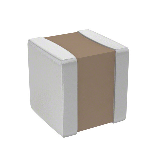
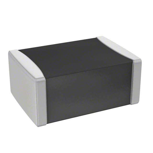
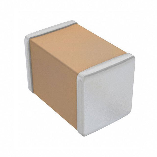
AVX Corporation的1210PC683KAT1A是一款陶瓷电容器,属于多层陶瓷电容器(MLCC)的一种。该型号的电容值为68nF(即683表示68×10³pF),容差为±10%(K级),额定电压为50V,封装尺寸为1210(约3.2mm x 2.5mm),适用于表面贴装技术(SMT)。

该型号陶瓷电容器主要应用于以下场景:

1. 电源管理电路:用于滤波、去耦和储能,提高电源稳定性,常见于DC-DC转换器、稳压器等电路中。

2. 通信设备:如基站、路由器和交换机,用于信号滤波和耦合,保障高频信号传输的稳定性。

3. 工业控制系统:在PLC、变频器、传感器等设备中用于抗干扰和信号处理。

4. 消费电子产品:如智能手机、平板电脑、电视机等,用于电源去耦和信号线路滤波,提升设备性能和可靠性。

5. 汽车电子:在车载导航、音响系统、控制模块中,提供稳定电容性能,适应较高温度和振动环境。

该电容器具有体积小、可靠性高、频率特性好等优点,广泛应用于高密度电子组装和中高频率电路中。
| 参数 | 数值 |
| 产品目录 | |
| 描述 | CAP CER 0.068UF 250V X7R 1210多层陶瓷电容器MLCC - SMD/SMT 250volts 0.068uF 10% X7R |
| 产品分类 | |
| 品牌 | AVX |
| 产品手册 | |
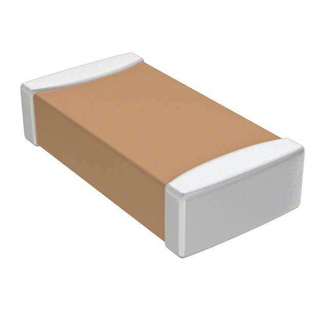
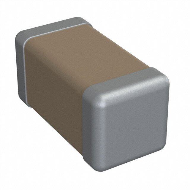
| 产品图片 |
|
| rohs | 符合RoHS无铅 / 符合限制有害物质指令(RoHS)规范要求 |
| 产品系列 | MLCC,多层陶瓷电容器MLCC - SMD/SMT,AVX 1210PC683KAT1A- |
| 数据手册 | |
| 产品型号 | 1210PC683KAT1A |
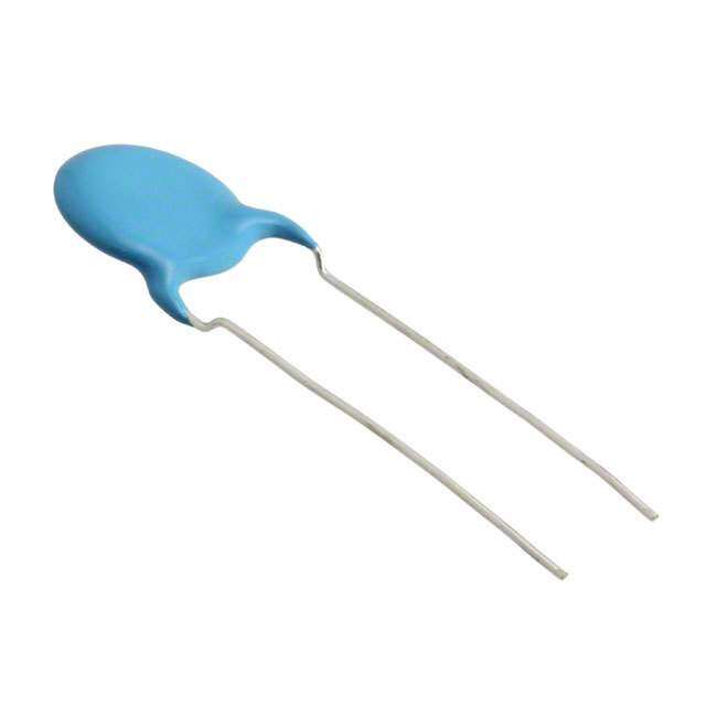
| 产品 | Tip & Ring MLCCs |
| 产品培训模块 | http://www.digikey.cn/PTM/IndividualPTM.page?site=cn&lang=zhs&ptm=21794http://www.digikey.cn/PTM/IndividualPTM.page?site=cn&lang=zhs&ptm=21795 |
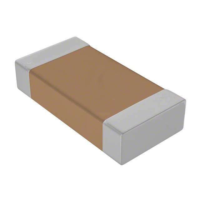
| 产品目录绘图 |
|
| 产品目录页面 | |
| 产品种类 | 多层陶瓷电容器MLCC - SMD/SMT |
| 其它名称 | 478-5566-1 |
| 包装 | 剪切带 (CT) |
| 厚度(最大值) | 0.070"(1.78mm) |
| 商标 | AVX |
| 外壳代码-in | 1210 |
| 外壳代码-mm | 3225 |
| 外壳宽度 | 2.5 mm |
| 外壳长度 | 3.2 mm |
| 外壳高度 | 1.78 mm |
| 大小/尺寸 | 0.126" 长 x 0.098" 宽(3.20mm x 2.50mm) |
| 安装类型 | 表面贴装,MLCC |
| 容差 | 10 % |
| 封装 | Reel |
| 封装/外壳 | 1210(3225 公制) |
| 封装/箱体 | 1210 (3225 metric) |
| 工作温度 | -55°C ~ 125°C |
| 工作温度范围 | - 55 C to + 125 C |
| 工厂包装数量 | 4000 |
| 应用 | 通用 |
| 引线形式 | - |
| 引线间距 | - |
| 损耗因数DF | 2.5 |
| 最大工作温度 | + 125 C |
| 最小工作温度 | - 55 C |
| 标准包装 | 1 |
| 温度系数 | X7R |
| 温度系数/代码 | +/- 15 % |
| 特性 | - |
| 电介质 | X7R |
| 电压-额定 | 250V |
| 电压额定值 | 250 V |
| 电压额定值DC | 250 V |
| 电容 | 0.068 uF |
| 端接类型 | SMD/SMT |
| 等级 | - |
| 类型 | Tip and Ring MLCCs |
| 高度-安装(最大值) | - |


- 商务部:美国ITC正式对集成电路等产品启动337调查
- 曝三星4nm工艺存在良率问题 高通将骁龙8 Gen1或转产台积电
- 太阳诱电将投资9.5亿元在常州建新厂生产MLCC 预计2023年完工
- 英特尔发布欧洲新工厂建设计划 深化IDM 2.0 战略
- 台积电先进制程称霸业界 有大客户加持明年业绩稳了
- 达到5530亿美元!SIA预计今年全球半导体销售额将创下新高
- 英特尔拟将自动驾驶子公司Mobileye上市 估值或超500亿美元
- 三星加码芯片和SET,合并消费电子和移动部门,撤换高东真等 CEO
- 三星电子宣布重大人事变动 还合并消费电子和移动部门
- 海关总署:前11个月进口集成电路产品价值2.52万亿元 增长14.8%


PDF Datasheet 数据手册内容提取
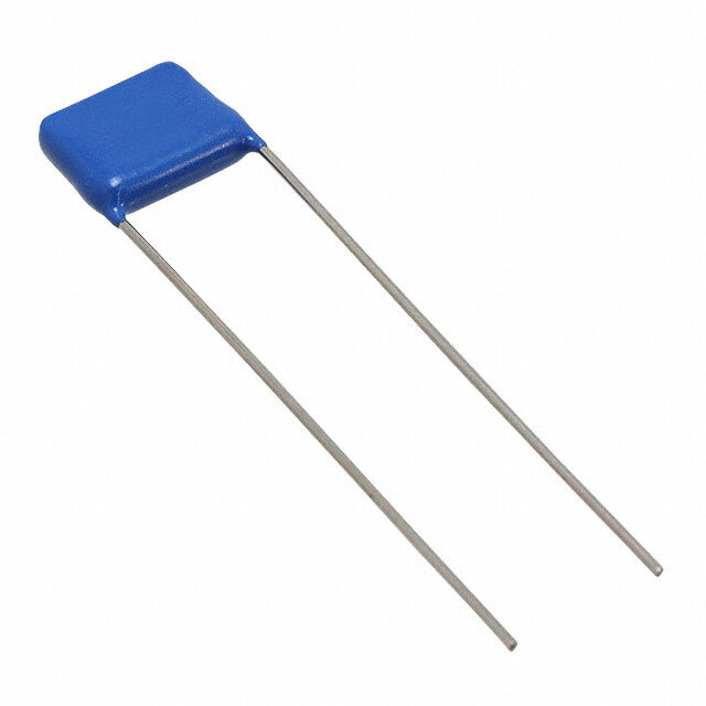
Tip & Ring Multilayer Ceramic Chip Capacitors AVX “Tip & Ring” or “ring detector” Multilayer Ceramic Chip Capacitors are designed as a standard telecom filter to block -48 Volts DC telephone line voltage and pass subscriber’s AC signal pulse (16 to 25Hz, 70 to 90Vrms). The typical ringing signal is seen on figure on page 132. The ringer capacitors replace large leaded film capacitors and are ideal for telecom/modem applications. Using AVX “Tip & Ring” capacitors not only saves valuable real estate on the board and reduces the weight of overall product, but also features standard surface mounting capabilities, so critical to new and compact designs. The AVX “Tip & Ring” capacitors are offered in standard EIA sizes and standard values. They offer excellent high frequency performance, low ESR and improved temperature performance over film capacitors. HOW TO ORDER 1812 P C 104 K A T 1 A AVX Voltage Temperature Capacitance Code Capacitance Test Termination Packaging Special Code Style 250 VDC Coefficient (2 significant digits Tolerance Level T = Plated 1 or 2 = 7" Reel A = Standard 0805 Telco X7R + no. of zeros) K = ±10% A = Standard Ni and Sn 3 or 4 = 13" Reel 1206 Rating Examples: M = ±20% (RoHS Compliant) 9 = Bulk 1210 1,000 pF = 102 Z = FLEXITERM® 1808 22,000 pF = 223 100% Tin 1812 220,000 pF = 224 (RoHS Compliant) 1825 1 µF =105 2220 2225 Contact factory for availability of Termination and Tolerance options for Specific Part Numbers. W L T t DIMENSIONS millimeters (inches) Style 0805 1206 1210* 1808* 1812* 1825* 2220* 2225* (L) Length 2.01 ± 0.20 3.20 ± 0.20 3.2 ± 0.20 4.57 ± 0.25 4.50 ± 0.30 4.50 ± 0.30 5.60 ± 0.30 5.60 ± 0.25 (0.079 ± 0.008) (0.126 ± 0.008) (0.126 ± 0.008) (0.180 ± 0.010) (0.177 ± 0.012) (0.177 ± 0.012) (0.220 ± 0.012)(0.220 ± 0.010) (W)Width 1.25 ± 0.20 1.60 ± 0.20 2.50 ± 0.20 2.03 ± 0.25 3.2 ± 0.20 6.34 ± 0.30 5.10 ± 0.40 6.35 ± 0.25 (0.049 ± 0.008) (0.063 ± 0.008) (0.098 ± 0.008) (0.080 ± 0.010) (0.126 ± 0.008) (0.252 ± 0.012) (0.200 ± 0.016)(0.250 ± 0.010) (T) Thickness 1.30 max. 1.50 max. 1.78 max. 1.78 max. 2.00 max. 2.00max. 2.00 max. 2.00 max. (0.051 max.) (0.059 max.) (0.070 max.) (0.070 max.) (0.080 max.) (0.080 max.) (0.080 max.) (0.080 max.) (t) terminal 0.50 ± 0.25 0.50 ± 0.25 0.50 ± 0.25 0.63 ± 0.38 0.63 ± 0.38 0.63 ± 0.38 0.63 ± 0.38 0.63 ± 0.38 (0.020 ± 0.010) (0.020 ± 0.010) (0.020 ± 0.010) (0.025 ± 0.015) (0.025 ± 0.015) (0.025 ± 0.015) (0.025 ± 0.015) (0.025 ± 0.015) *Reflow Soldering Only 131 062216
Tip & Ring Multilayer Ceramic Chip Capacitors CAPACITANCE RANGE (µF) Size 0805 1206 1210 1808 1812 1825 2220 2225 min. 0.0010 0.0010 0.0010 0.010 0.10 0.33 0.47 0.47 max. 0.027 0.082 0.22 0.27 0.47 1.0 1.0 1.2 “TIP & RING” GRAPH 250V Tip & Ring 0 -48V -250V -400ms 200ms/div 1.6s PERFORMANCE CHARACTERISTICS Capacitance Range 1000 pF to 1.2 µF (25°C, 1.0 ±0.2 Vrms at 1kHz) Capacitance Tolerances ±10%, ±20% Dissipation Factor 2.5% max. (25°C, 1.0 ±0.2 Vrms at 1kHz) Operating Temperature Range -55°C to +125°C Temperature Characteristic X7R ±15% (0 VDC) Voltage Rating 250 VDC Telco rating Insulation Resistance 1000 megohm-microfarad min. Dielectric Strength Minimum 200% rated voltage for 5 seconds at 50 mA max. current 132 062216