ICGOO在线商城 > 传感器,变送器 > 磁性器件 - 多用途 > 106MG10

 Datasheet下载
- 型号: 106MG10
- 制造商: Honeywell Solid State Electronics
- 库位|库存: xxxx|xxxx
- 要求:
| 数量阶梯 | 香港交货 | 国内含税 |
| +xxxx | $xxxx | ¥xxxx |
查看当月历史价格
查看今年历史价格
106MG10产品简介:
ICGOO电子元器件商城为您提供106MG10由Honeywell Solid State Electronics设计生产,在icgoo商城现货销售,并且可以通过原厂、代理商等渠道进行代购。 106MG10价格参考。Honeywell Solid State Electronics106MG10封装/规格:磁性器件 - 多用途, Magnet Rare Earth 0.400" Dia x 0.930" H (10.2mm x 23.6mm)。您可以下载106MG10参考资料、Datasheet数据手册功能说明书,资料中有106MG10 详细功能的应用电路图电压和使用方法及教程。
Honeywell Sensing and Productivity Solutions 旗下的型号为 106MG10 的磁性器件,属于多用途磁性开关,常用于需要检测位置或运动的场合。该器件主要基于磁簧开关技术,具有结构紧凑、响应迅速、可靠性高的特点。

其典型应用场景包括:

1. 工业自动化:用于检测气缸、阀门或机械臂的位置状态,实现自动控制与反馈。
2. 安防系统:作为门窗开关传感器,广泛应用于报警系统或智能安防设备中。
3. 家电控制:如洗衣机、微波炉等电器中用于检测门是否关闭到位。
4. 物流设备:用于输送带或自动分拣系统中检测物体位置或行程控制。
5. 医疗设备:在需要精确位置感应的医疗仪器中,用于安全联锁或状态监测。

该器件适用于需要非接触式检测、环境较为复杂、对可靠性要求较高的场合。
| 参数 | 数值 |
| 产品目录 | |
| 描述 | SPEED/POSITION MAGNETIC SENSORS传感器硬件与配件 Unipolar 1/4-20 plasti pck. |
| 产品分类 | |
| 品牌 | Honeywell Sensing and Control |
| 产品手册 | |
| 产品图片 |
|
| rohs | 符合RoHS无铅 / 符合限制有害物质指令(RoHS)规范要求 |
| 产品系列 | Honeywell 106MG10* |
| 数据手册 | |
| 产品型号 | 106MG10 |
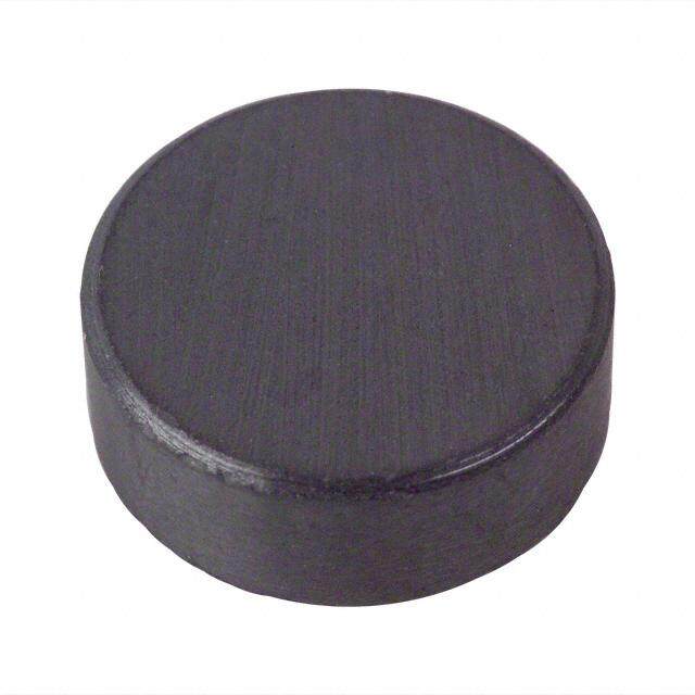
| 产品 | Ring Magnets |
| 产品种类 | 传感器硬件与配件 |
| 其它名称 | 106MG10-ND |
| 商标 | Honeywell |
| 封装 | Bulk |
| 工厂包装数量 | 10 |
| 标准包装 | 10 |
| 用于 | Hall Effect Sensors |


- 商务部:美国ITC正式对集成电路等产品启动337调查
- 曝三星4nm工艺存在良率问题 高通将骁龙8 Gen1或转产台积电
- 太阳诱电将投资9.5亿元在常州建新厂生产MLCC 预计2023年完工
- 英特尔发布欧洲新工厂建设计划 深化IDM 2.0 战略
- 台积电先进制程称霸业界 有大客户加持明年业绩稳了
- 达到5530亿美元!SIA预计今年全球半导体销售额将创下新高
- 英特尔拟将自动驾驶子公司Mobileye上市 估值或超500亿美元
- 三星加码芯片和SET,合并消费电子和移动部门,撤换高东真等 CEO
- 三星电子宣布重大人事变动 还合并消费电子和移动部门
- 海关总署:前11个月进口集成电路产品价值2.52万亿元 增长14.8%
PDF Datasheet 数据手册内容提取
MG Series Magnets Datasheet
MG Series Magnets The MG Series magnets offered by Honeywell Sensing and Control includes several bar magnets in various sizes and strengths for actuating Hall-effect and magnetoresistive sensor ICs. These bar magnets are for use in sensors with unipolar or omnipolar magnetic characteristics. Made from different magnetic materials and available in a variety of sizes and shapes, the MG Series magnets can be used for evaluation and design of magnetic systems, and in numerous potential applications across a variety of different industries. Some of these magnets are offered with threaded bushings for easy installation and have a good resistance to demagnetization which could be caused by magnetic shock. These magnets are designed to provide minimum magnetic fields at a specified distance to help system designers match the appropriate magnet to their requirements. Value to the Customer Variety of sizes, shapes, and packaging options to choose from The MG Series consists of a range of magnets based on varying dimensions and packaging types to help customers identify the most appropriate magnet that can be used to evaluate Honeywell’s Hall-effect and magnetoresistive sensor ICs in their applications. DID YOU KNOW? Magnetic sensing characteristics of Hall-effect sensor ICs are specified within particular ranges. For example, assume an application with a temperature range of -40 °C to 125 °C [-40 °F to 257 °F] using an SS443A. The operate point may be up to 215 Gauss [21.5 mT] and the release point may be 60 Gauss to 190 Gauss [6.0 mT to 19.0 mT]. To ensure reliable operation, at least 215 Gauss [21.5 mT] must be presented to the sensor. For a robust activation, the flux from the magnet at the maximum operating gap should be 20 % to 100 % higher than the sensor’s maximum operating point over temperature. The Gauss level must then be reduced below 60 Gauss [6.0 mT] to ensure that the sensor will release. Therefore, it is necessary to know the flux density (Gauss) measured at the chip to be able to: • Select a device with the best magnetic characteristics for the application • Select the best magnet • Verify the desired mechanical characteristics COMPACT SIZE • WIDE RANGE • VARIETY OF SHAPES 2 sensing.honeywell.com
Features PHYSICAL STRENGTH and Benefits The MG Series offers Alnico or Indox magnets which exhibit good physical strength. MAGNETIC FIELD Rare Earth (SmCo-Samarium Cobalt) magnets from MG Series offer strong magnetic field in compact sizes. Choose the best fit option MAGNETIC MATERIAL Honeywell’s MG Series offer magnets made from different magnetic materials allowing customers to choose the most suitable option for their application. OPERATING TEMPERATURE The MG Series magnets exhibit good stability over a wide range of operating temperatures, as low as -40 °C [-40 °F] or as high as 140 °C [284 °F] to 300 °C [572 °F], depending on the magnet. OPERATING MAGNETIC GAUSS LEVELS The MG Series offers a wide selection of magnets operating across various magnetic Gauss levels to choose from. Potential Applications These magnets are used as actuators for Hall-effect and magnetoresistive sensor ICs which in turn can be used in a number of potential industrial and medical applications. INDUSTRIAL • Door or lid closure detection in appliances or electronically controlled containers The unipolar sensor recessed in the door frame with a magnet embedded in the door can help in sensing the open and close positions in doors or lids in appliances or electronically controlled containers. • Simple speed and RPM (revolutions per minute) sensing in fitness and industrial equipment A single magnet of appropriate polarity mounted on the motor shaft of a treadmill when actuates a unipolar Hall-effect sensor IC generates single digital pulse for each revolution which in turn can help measure the speed or RPM of the equipment. MEDICAL • Position sensor in hospital beds and medical equipment Magnets can be used to determine the home or end-of-travel position of the equipment on an activator arm of hospital beds and medical equipment. • Medication bin monitor on portable drug carts These magnets can be mounted on a drug dispensing drawer to detect the open or close position using a unipolar Hall-effect sensor IC. sensing.honeywell.com 3
MG Series MAGNET CURVES The curves shown on the graphs are typical plots of induction (Gauss) versus distance for various magnets. Mode of operation: Head-on Figure 1. 101MG2L1 Figure 2. 101MG3 Distance [mm] Distance [mm] 0,25 0,76 1,27 2,54 3,81 5,08 0,25 0,76 1,27 2,54 3,81 5,08 800 1600 700 1400 600 1200 500 1000 uss 400 uss 800 a a G G 300 600 200 400 100 200 0 0 0.01 0.03 0.05 0.1 0.15 0.2 0.01 0.03 0.05 0.1 0.15 0.2 Distance [in] Distance [in] Figure 3. 101MG7 Figure 4. 101MG8 Distance [mm] Distance [mm] 0,25 0,76 1,27 2,54 3,81 5,08 0,25 0,76 1,27 2,54 3,81 5,08 1200 1200 1000 1000 800 800 s s s s u 600 u 600 a a G G 400 400 200 200 0 0 0.01 0.03 0.05 0.1 0.15 0.2 0.01 0.03 0.05 0.1 0.15 0.2 Distance [in] Distance [in] Figure 5. 102MG11 Figure 6. 102MG15 Distance [mm] Distance [mm] 0,25 0,76 1,27 2,54 3,81 5,08 0,25 0,76 1,27 2,54 3,81 5,08 1200 1200 1000 1000 800 800 s s s s u 600 u 600 a a G G 400 400 200 200 0 0 0.01 0.03 0.05 0.1 0.15 0.2 0.01 0.03 0.05 0.1 0.15 0.2 Distance [in] Distance [in] 4 sensing.honeywell.com
MG Series Magnets Figure 7. 103MG5 Figure 8. 103MG8 Distance [mm] Distance [mm] 0,25 0,76 1,27 2,54 3,81 5,08 0,25 0,76 1,27 2,54 3,81 5,08 1200 3000 1000 2500 800 2000 s s us 600 us 1500 a a G G 400 1000 200 500 0 0 0.01 0.03 0.05 0.1 0.15 0.2 0.01 0.03 0.05 0.1 0.15 0.2 Distance [in] Distance [in] Figure 9. 104MG1 Figure 10. 104MG2 Distance [mm] Distance [mm] 0,25 0,76 1,27 2,54 3,81 5,08 0,25 0,76 1,27 2,54 3,81 5,08 1200 3000 1000 2500 800 2000 s s s s u 600 u1500 a a G G 400 1000 200 500 0 0 0.01 0.03 0.05 0.1 0.15 0.2 0.01 0.03 0.05 0.1 0.15 0.2 Distance [in] Distance [in] Figure 11. 104MG3 Figure 12. 106MG10 Distance [mm] Distance [mm] 0,25 0,76 1,27 2,54 3,81 5,08 0,25 0,76 1,27 2,54 3,81 5,08 2500 3000 2500 2000 2000 1500 Gauss Gauss 1500 1000 1000 500 500 0 0 0.01 0.03 0.05 0.1 0.15 0.2 0.01 0.03 0.05 0.1 0.15 0.2 Distance [in] Distance [in] sensing.honeywell.com 5
MG Series Figure 13. 107MG1 Distance [mm] 0,25 0,76 1,27 2,54 3,81 5,08 8000 7000 6000 5000 s s u4000 a G 3000 2000 1000 0 0.01 0.03 0.05 0.1 0.15 0.2 Distance [in] Mode of operation: Slide-by Figure 14. 101MG2L1 Figure 15. 101MG3 Distance [mm] Distance [mm] -10,2 -8,9 -7,6 -6,4 -5,1 -3,8 -2,5 -1,3 0 1,3 2,5 3,8 5,1 6,4 7,6 8,9 10,2 -19,1 -16,5 -13,1 -11,4 -8,9 -6,4 -3,8 -1,3 0 1,3 3,8 6,4 8,9 11,4 13,1 16,5 19,1 450 500 400 450 350 400 350 300 300 Gauss 225000 Gauss 250 200 150 150 100 100 50 50 0 0 4 5 3 5 2 5 1 5 0 5 1 5 2 5 3 5 4 5 5 5 5 5 5 5 5 0 5 5 5 5 5 5 5 5 -0. 0.3 -0. 0.2 -0. 0.1 -0. 0.0 0.0 0. 0.1 0. 0.2 0. 0.3 0. 0.7 0.6 0.5 0.4 0.3 0.2 0.1 0.0 0.0 0.1 0.2 0.3 0.4 0.5 0.6 0.7 - - - - - - - - - - - - Distance [in] Distance [in] Figure 16. 101MG7 Figure 17. 103MG5 Distance [mm] Distance [mm] -13,1 -11,4 -8,9 -6,4 -3,8 -1,3 1,3 3,8 6,4 8,9 11,4 13,1 2,5 5,1 400 14 Gap 350 0[0,.2051 minm] Gap 12 300 3,81 mm [0.15 in] 250 10 Gap 0,51 mm Gauss 210500 uss x 100 8 [0.02 in] a 100 G 6 50 4 0 -50 2 -0.55 -0.45 -0.35 -0.25 -0.15 -0.05 0.05 0.15 0.25 0.35 0.45 0.55 0 0.10 0.20 Distance [in] Distance [in] 6 sensing.honeywell.com
MG Series Magnets Figure 18. 103MG8 Figure 19. 106MG10 Distance [mm] Distance [mm] -15,2 -12,7 -10,2 -7,6 -5,1 -2,5 0 2,5 5,1 7,6 10,2 12,7 15,2 7,6 5,1 2,5 0 2,5 5,1 7,6 550 Gap 0,76 mm [0.03 in] 450 Gap 5,08 mm [0.20 in] 20 350 Gap Gauss 250 ss x 100 1[0,.2075 minm] au 10 150 G Gap 2,54 mm 50 [0.10 in] -50 -0.6 -0.5 -0.4 -0.3 -0.2 -0.1 0 0.1 0.2 0.3 0.4 0.5 0.6 0.30 0.20 0.10 0 0.10 0.20 0.30 Distance [in] Distance [in] Figure 20. 107MG1 Distance [mm] -13,1 -11,4 -8,9 -6,4 -3,8 -1,3 1,3 3,8 6,4 8,9 11,4 13,1 450 400 Gap 350 5,08 mm [0.20 in] 300 uss 250 a G 200 150 100 50 0 5 5 5 5 5 5 5 5 5 5 5 5 5 4 3 2 1 0 0 1 2 3 4 5 0. 0. 0. 0. 0. 0. 0. 0. 0. 0. 0. 0. - - - - - - Distance [in] sensing.honeywell.com 7
MG Series METHOD OF MAGNET ACTUATION There are many ways to apply magnets in Hall-effect sensor applications. The more common methods are described below. HEAD-ON ACTUATION For “head-on” actuation, there should be sufficient magnet travel to provide at least 10 % flux overdrive of both maximum operate and minimum release characteristics of the sensor. The target is centered over the point of maximum sensitivity and is moved “head-on” to the sensor, then backed off. Magnetic field Figure 21. Unipolar Head-on (Gauss) G1 G2 D1 D2 Distance Arrow indicates direction S of magnetic flux Distance Motion of magnet SLIDE-BY ACTUATION For “slide-by” actuation, the magnet should pass the sensing surface at a distance which provides at least 10 % flux overdrive above maximum operate. The target is moved across the face of the sensor at a specified distance. Figure 22. Magnetic field Figure 23. Magnetic field (Gauss) (Gauss) Unipolar Slide-by Bipolar Slide-by G1 (One magnet) (One magnet) G2 D4 D3 D2 D1 Distance -D2 -D1 D1 D2 Distance Motion of magnet Motion of magnet N N S Arrow indicates direction of Arrow indicates magnetic flux Gap direction of magnetic flux Gap Distance Distance Figure 24. Magnetic field Figure 25. Output voltage (Gauss) (Volts) Bipolar Slide-by Bipolar Slide-by (Two magnets) (Three magnets) Distance Input field Motion of magnet Motion of magnet N S Arrow indicates Arrow indicates direction of direction of magnetic flux Gap magnetic flux Gap Distance Distance 8 sensing.honeywell.com
MG Series Magnets MAGNET CONVERSION CHART Table 1. Multiplication Factors From / To Gauss Tesla Millitesla Weber/Inch2 Weber/Meter2 Line/Inch2 Gammas Gauss 1.0 1.0 × 10⁴ 10 1.55 × 10⁷ 1.0 × 10⁴ 1.55 × 10⁷ 1.0 × 10⁻⁵ Tesla 1.0 × 10⁻⁴ 1.0 1.0 × 10⁻³ 1.55 × 10³ 1.0 1.55 × 10³ 1.0 × 10⁻⁹ Millitesla 0.1 1.0 × 10³ 1.0 1.55 × 10⁻⁴ 1.0 × 10³ 1.55 × 10⁶ 1.0 × 10⁻⁶ Weber/Inch2 6.4516 × 10⁻⁵ 6.4516 × 10⁻⁴ 6.4516 × 10⁻² 1.0 6.4516 × 10⁶ 1.0 6.4516 × 10⁻¹³ Weber/Meter2 1.0 × 10⁻⁴ 1.0 1.0 × 10⁻³ 1.55 × 10³ 1.0 1.55 × 10³ 1.0 × 10⁻⁹ Line/Inch2 6.4516 × 10⁻⁵ 6.4516 × 10⁻⁴ 6.4516 × 10⁻² 1.0 6.4516 × 10⁶ 1.0 6.4516 × 10⁻¹³ Gammas 1.0 × 10⁶ 1.0 × 10⁹ 1.0 × 10⁶ 1.55 × 10¹² 1.0 × 10⁹ 1.55 × 10¹² 1.0 Table 2. Various Magnetic Materials Magnetic Material (B H ) – Peak Energy Product (B ) – Residual Induction Gauss (H ) – Coercive Force Oersteds D D R C Alnico V 5.5 × 10⁶ 12800 640 Alnico VIII 6.0 × 10⁶ 9200 1550 Rare Earth (SmCo magnet) 18.0 × 10⁶ 8600 8000 DIMENSIONAL DRAWINGS (FOR REFERENCE ONLY) Figure 26. Alnico VI Sintered – 101MG2L1 Figure 27. Alnico V Cast – 101MG3 3,18 mm [0.125 in] 6,35 mm [ 0.25 in] ‘N’ end identified 3,18 mm with red [0.125 in] ‘N’ end indicated with red N n o ati 9[,05.33 7m5m in ± ±00,2.051 m inm] netiz 3[11,.7255 minm] g a m of S xis A 2,54 mm ±0,03 mm [0.10 in ±0.001 in] Location of Hall probe 5,21 mm ±0,03 mm Location of Hall probe [0.205 in ±0.001 in] sensing.honeywell.com 9
MG Series Figure 28. Alnico VIII Sintered – 101MG7 Figure 29. Alnico VIII Sintered – 101MG8 6,35 mm ±0,25 mm 6,22 mm [ 0.25 in ±0.01 in] [ 0.245 in] ‘N’ end identified ‘N’ end identified n with red o with red netizati ation 6,[305.2 m5 min ±±00,.2051 min]m N Axis of mag [60,.2224 5m imn] xis of magnetiz A 2[,05.41 0m imn ±±00.,00031 m inm] S 2[,05.41 0m imn ±±00.,00031 m inm] Location of Hall probe Location of Hall probe Figure 30. Alnico VIII Sintered – 102MG11 Figure 31. Alnico VIII Sintered – 102MG15 7,87 mm 7,87 mm [ 0.31 in] [ 0.31 in] [00,.8013 2m imn] Slot 8-32 Thread 4-40 Thread 2,54 mm1 [7±0,0.06,207 3 mi nmm]7m[0,6.320 m inm] Axis of magnetization 1[20,.1498 minm] Axis of magnetization [0.10 in ±0.001 in] 2,54 mm ±0,03 mm South Pole [0.10 in ±0.001 in] South Pole Location of Hall probe Location of Hall probe Figure 32. Rare Earth Pressed – 103MG5 Figure 33. Rare Earth Pressed – 103MG8 1,98 mm [0.078 in] Magnetized direction 5,59 mm ±0,25 mm 5,08 mm 1,98 mm [0.22 in ±0.01 in] [0.20 in] [0.078 in] 5,59 mm ±0,25 mm [0.22 in ±0.01 in] 1,02 mm [0.04 in] 2,54 mm ±0,03 mm 0,76 mm max. R (4) [0.10 in ±0.001 in] [0.03 in max. R (4)] 2,54 mm 3,05 mm ±0,03 mm [0.10 in] [0.12 in ±0.001 in] Location of Hall probe Location of Hall probe 10 sensing.honeywell.com
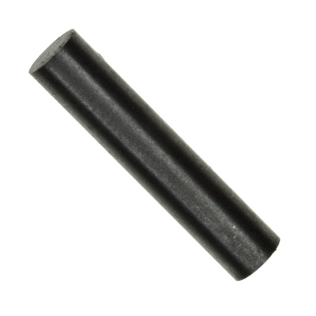
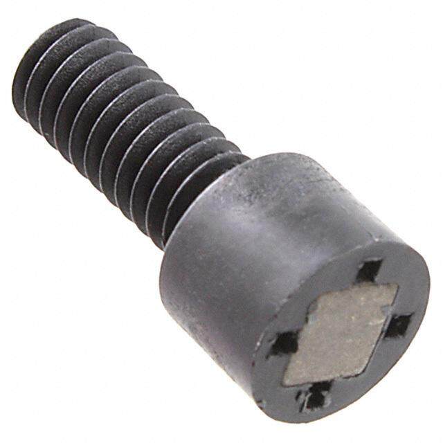
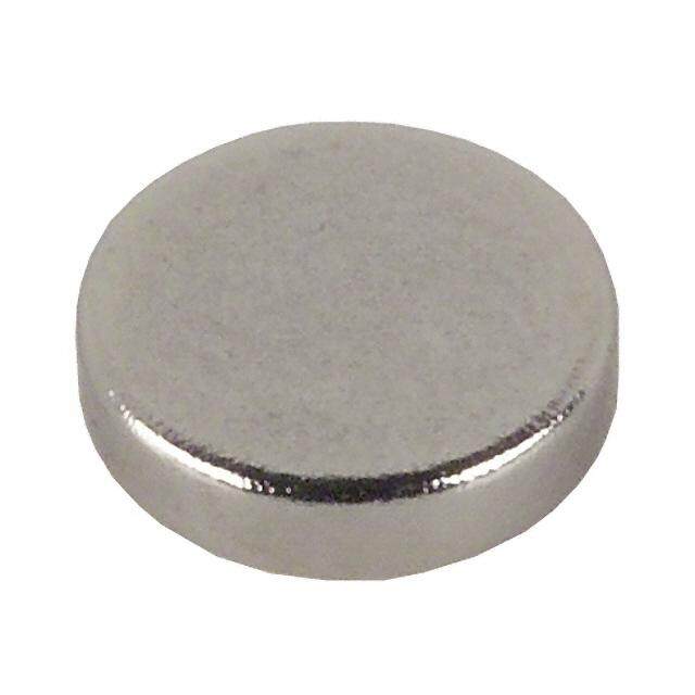
MG Series Magnets Figure 34. Rare Earth Pressed – 104MG1 Figure 35. Rare Earth Pressed – 104MG2 1,98 mm 3,18 mm [0.078 in] [0.125 in] 1,98 mm 3,18 mm [0.078 in] [0.125 in] 1,02 mm 1,02 mm [0.04 in] [0.04 in] 2,54 mm ±0,03 mm 2,54 mm ±0,03 mm [0.10 in ±0.001 in] [0.10 in ±0.001 in] Location of Hall probe Location of Hall probe Figure 36. Rare Earth Pressed – 104MG3 Figure 37. Rare Earth Pressed – 106MG10 3,96 mm 10,16 mm [0.156 in] [ 0.40 in] 1,98 mm [0.078 in] 2,54 mm [ 0.10 in] 1/4-20 plastic thread 12,7 mm [0.50 in] 1,02 mm 23,62 mm Axis of magnetization [0.04 in] [0.93 in] 2,54 mm ±0,03 mm 7,62 mm [0.10 in ±0.001 in] [0.30 in] Rare Earth magnet 5,21 mm ±0,03 mm [0.205 in ±0.001 in] S Location of Hall probe Location of Hall probe Figure 38. Alnico VIII Sintered – 107MG1 15/32-32 UNS-2A 25,4 mm ±1,02 mm 2X hex nut [1.0 in ±0.04 in] South Pole Date code sensing.honeywell.com 11
MG Series MAGNET SELECTION GUIDE The below guide is designed to aid in determining the best magnet for use with a Hall-effect or magnetoresistive sensor. There are several factors to consider when choosing a magnet. The most important is gap distance. There must be a strong enough magnetic Gauss level to operate the sensor at the correct distance. By using the maximum operate magnetic Gauss characteristics, you can determine which magnet will operate the sensor. The other important factors include temperature and physical environment of the application. The Gauss levels below are typical values only and not guaranteed rated specifications. Table 3. Magnet Selection Guide ck o on Gap Distance mm [in]** and Gauss Level (G) Material ho ce e t ati @ 25 °C [77 °F] † CLaisttailnogg Proancdess SPthryesnigctahl TemRpanegraet*ure gnetic S Resistan esistanc magnetiz 0,25 mm 0,76 mm 1,27 mm 2,54 mm 3,81 mm 5,08 mm Ma R De [0.01 in] [0.03 in] [0.05 in] [0.10 in] [0.15 in] [0.20 in] Alnico VI -40 °C to 250 °C 101MG2L1 Good Good Good 730 550 410 205 115 75 Sintered -40 °F to 482 °F Alnico V -40 °C to 300 °C 101MG3 Good Poor Fair 1460 1320 1170 810 575 420 Cast -40 °F to 572 °F Alnico VIII -40 °C to 250 °C 101MG7 Good Good Excellent 1050 900 755 470 295 195 Sintered -40 °F to 482 °F Alnico VIII -40 °C to 250 °C 101MG8 Good Good Excellent 1050 900 755 470 295 195 Sintered -40 °F to 482 °F Alnico VIII -40 °C to 140 °C 102MG11 Good Good Excellent 1050 900 755 470 295 195 Sintered -40 °F to 284 °F Alnico VIII -40 °C to 140 °C 102MG15 Good Good Excellent 1050 900 755 470 295 195 Sintered -40 °F to 284 °F Rare Earth -40 °C to 200 °C 103MG5 Poor Good Excellent 1110 630 365 120 55 25 Pressed -40 °F to 392 °F Rare Earth -40 °C to 200 °C 103MG8 Poor Good Excellent 2620 2100 1600 940 550 350 Pressed -40 °F to 392 °F Rare Earth -40 °C to 150 °C 104MG1 Poor Good Excellent 1110 630 365 120 55 25 Pressed -40 °F to 302 °F Rare Earth -40 °C to 150 °C 104MG2 Poor Good Excellent 2500 1600 1000 370 140 70 Pressed -40 °F to 302 °F Rare Earth -40 °C to 150 °C 104MG3 Poor Good Excellent 2350 1400 800 280 100 50 Pressed -40 °F to 302 °F Rare Earth -40 °C to 150 °C 106MG10 Poor Good Excellent 2620 2100 1600 940 550 350 Pressed -40 °F to 302 °F Alnico VIII -40 °C to 140 °C 107MG1*** Good Good Excellent 7800 7800 7800 750 550 375 Sintered -40 °F to 284 °F *Magnet exibits good stability over indicated temperature range **Gap distance from sensing surface ***Measurement device saturated @ 800 Gauss †Millitesla = Gauss × 10-1 12 sensing.honeywell.com
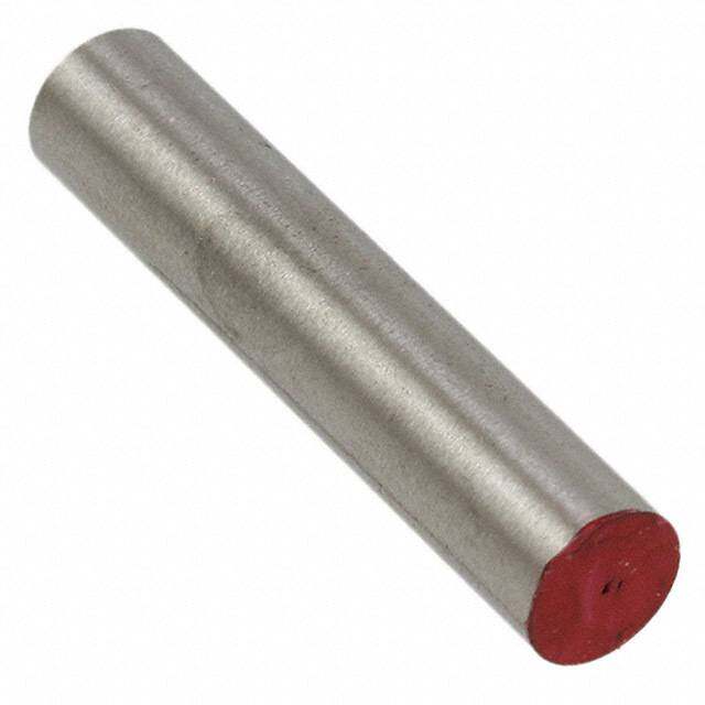
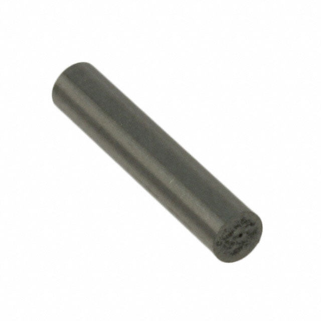
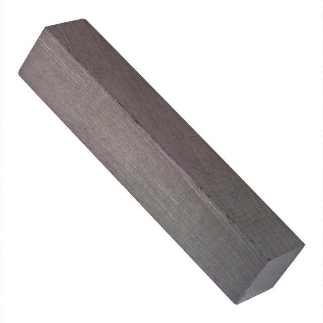
MG Series Magnets Order Guide (Measurements for reference only) Catalog Material and Dimension Description Listing Process Alnico VI 9,53 mm L x 3,18 mm W x 3,18 mm H Bar magnet; 101MG2L1 Sintered [0.375 in L x 0.125 in W x 0.125 in H] North Pole is indicated with red Alnico V 31,75 mm L x 6,35 mm dia Cylindrical magnet; 101MG3 Cast [1.25 in L x 0.25 in dia] North Pole is indicated with red Alnico VIII 6,35 mm L x 6,35 mm dia Cylindrical magnet; 101MG7 Sintered [0.25 in L x 0.25 in dia] North Pole is indicated with red Cylindrical magnet; Alnico VIII 6,35 mm L x 6,35 mm dia 101MG7-BP North Pole is indicated with red; Sintered [0.25 in L x 0.25 in dia] bulk packaging in 100 unit lots Cylindrical magnet; Alnico VIII 6,22 mm L x 6,22 mm dia 101MG8-BP North Pole is indicated with red; Sintered [0.245 in L x 0.245 in dia] bulk packaging in 100 unit lots Alnico VIII 17,02 mm L x 7,87 mm dia Magnet with 8 x 32 threaded shaft 102MG11 Sintered [0.67 in L x 0.31 in dia] for easy installation Magnet with 8 x 32 threaded shaft Alnico VIII 17,02 mm L x 7,87 mm dia 102MG11-BP for easy installation; Sintered [0.67 in L x 0.31 in dia] bulk packaging in 100 unit lots Alnico VIII 12,19 mm L x 7,87 mm dia Magnet with 4-40 threaded shaft 102MG15 Sintered [0.48 in L x 0.31 in dia] for easy installation Magnet with 4-40 threaded shaft Alnico VIII 12,19 mm L x 7,87 mm dia 102MG15-BP for easy installation; Sintered [0.48 in L x 0.31 in dia] bulk packaging in 100 unit lots Rare Earth 1,98 mm L x 1,98 mm W x 1,02 mm H 103MG5 Square magnet; 125 pieces per tube Pressed [0.078 in L x 0.078 in W x 0.04 in H] •BP - Bulk Pack sensing.honeywell.com 13
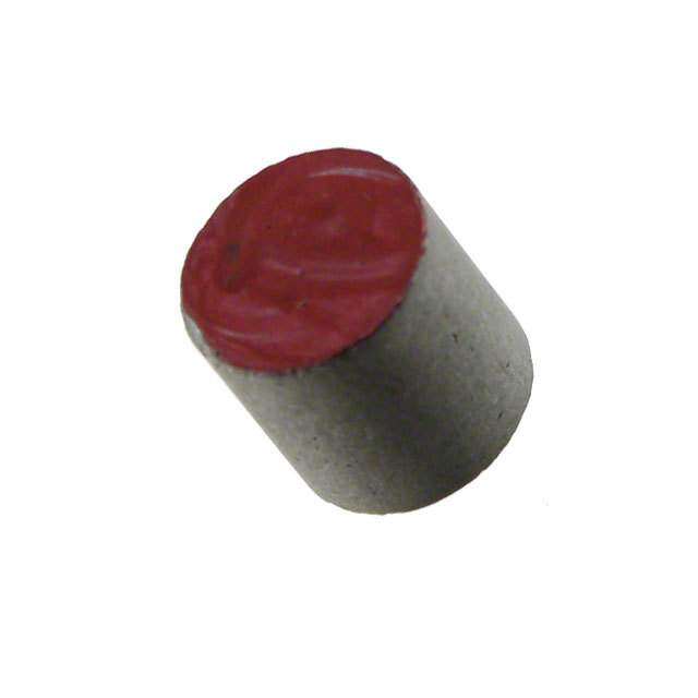
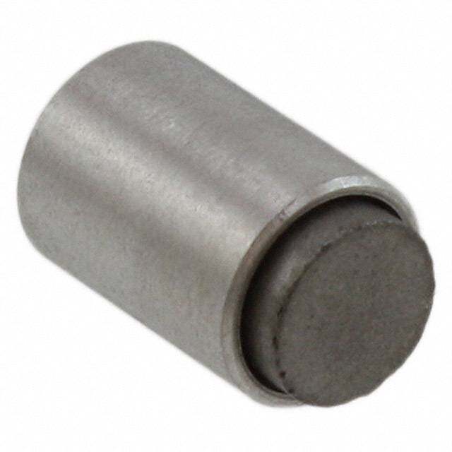
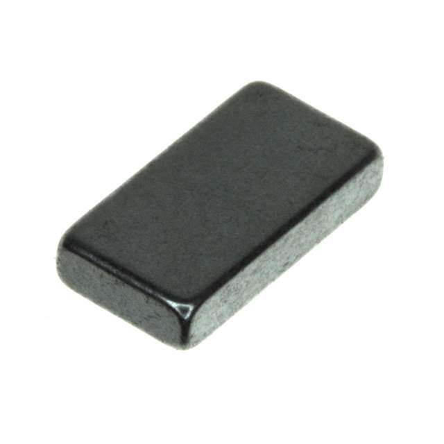
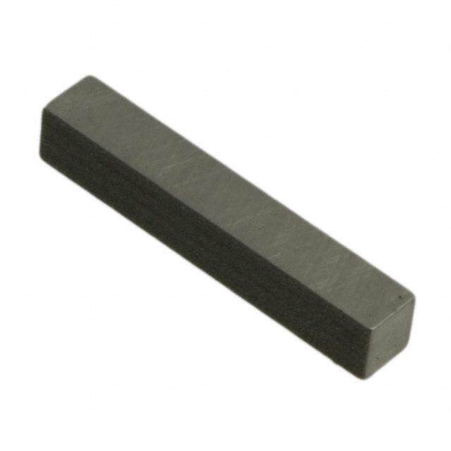
MG Series Order Guide (Measurements for reference only) Catalog Material and Dimension Description Listing Process Rare Earth 5,59 mm L x 5,08 mm W x 5,59 mm H 103MG8 Bar magnet Pressed [0.22 in W x 0.20 in W x 0.22 in H] Bar magnet, magnetized and conditioned Rare Earth 1,98 mm L x 1,02 mm W x 1,98 mm H 104MG1 for operation; tube is marked with a red dot Pressed [0.078 in L x 0.04 in W x 0.078 in H] indicating North Pole; 125 pieces per tube Rare Earth 3,18 mm L x 1,02 mm W x 3,18 mm H 104MG2 Bar magnet; 125 pieces per tube Pressed [0.125 in L x 0.04 in W x 0.125 in H] Rare Earth 3,96 mm L x 1,02 mm W x 1,98 mm H Bar magnet, magnetized and conditioned 104MG3 Pressed [0.156 in L x 0.04 in W x 0.078 in H] for operation; 125 pieces per tube Rare Earth 23,62 mm L x 10,16 mm dia Magnet in threaded plastic holder; 106MG10 Pressed [0.93 in L x 0.4 in dia] 1/4-20 thread for easy installation Magnet in threaded plastic holder; Rare Earth 23,62 mm L x 10,16 mm dia 106MG10-BP 1/4-20 thread for easy installation; Pressed [0.93 in L x 0.4 in dia] bulk packaging in 100 unit lots Alnico VIII 25,4 mm L x 0,47 mm dia Magnet in epoxy filled 15/32-32 UNS-2A 107MG1 Sintered [1.00 in L x 15/32-32 UNS-2A dia] aluminum package; 2 hex nuts; 1 per box •BP - Bulk Pack 14 sensing.honeywell.com
MG Series Magnets WARNING PERSONAL INJURY DO NOT USE these products as safety or emergency stop devices or in any other application where failure of the product could result in personal injury. Failure to comply with these instructions could result in death or serious injury. WARNING MISUSE OF DOCUMENTATION • The information presented in this product sheet is for reference only. Do not use this document as a product installation guide. • Complete installation, operation, and maintenance information is provided in the instructions supplied with each product. Failure to comply with these instructions could result in death or serious injury. WARRANTY/REMEDY Honeywell warrants goods of its manufacture as being free of defective materials and faulty workmanship. Honeywell’s standard product warranty applies unless agreed to otherwise by Honeywell in writing; please refer to your order acknowledgement or consult your local sales office for specific warranty details. If warranted goods are returned to Honeywell during the period of coverage, Honeywell will repair or replace, at its option, without charge those items it finds defective. The foregoing is buyer’s sole remedy and is in lieu of all other warranties, expressed or implied, including those of merchantability and fitness for a particular purpose. In no event shall Honeywell be liable for consequential, special, or indirect damages. While we provide application assistance personally, through our literature and the Honeywell website, it is up to the customer to determine the suitability of the product in the application. Specifications may change without notice. The information we supply is believed to be accurate and reliable as of this printing. However, we assume no responsibility for its use. sensing.honeywell.com 15
Find out more Honeywell serves its customers through a worldwide network of sales offices, representatives and distributors. For application assistance, current specifications, pricing or name of the nearest Authorized Distributor, contact your local sales office. To learn more about Honeywell’s sensing and control products, call +1-815-235-6847 or 1-800-537-6945, visit sensing.honeywell.com, or email inquiries to info.sc@honeywell.com Sensing and Control Honeywell 1985 Douglas Drive North Golden Valley, MN 55422 005972-1-EN IL50 GLO June 2014 honeywell.com Copyright 2014 Honeywell International Inc. All rights reserved. 16 sensing.honeywell.com
Mouser Electronics Authorized Distributor Click to View Pricing, Inventory, Delivery & Lifecycle Information: H oneywell: 101MG8-BP 104MG3 102MG15 102MG11 106MG10 101MG2L1