 Datasheet下载
- 型号: 101X18W104MV4E
- 制造商: Johanson Dielectrics Inc.
- 库位|库存: xxxx|xxxx
- 要求:
| 数量阶梯 | 香港交货 | 国内含税 |
| +xxxx | $xxxx | ¥xxxx |
查看当月历史价格
查看今年历史价格
101X18W104MV4E产品简介:
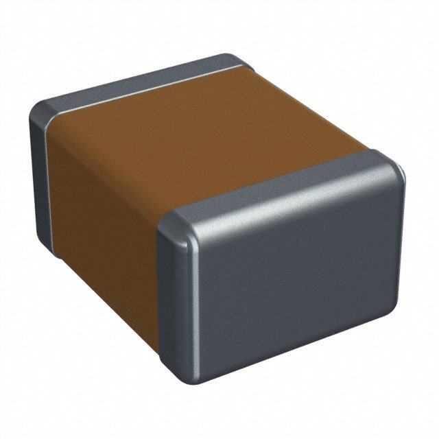
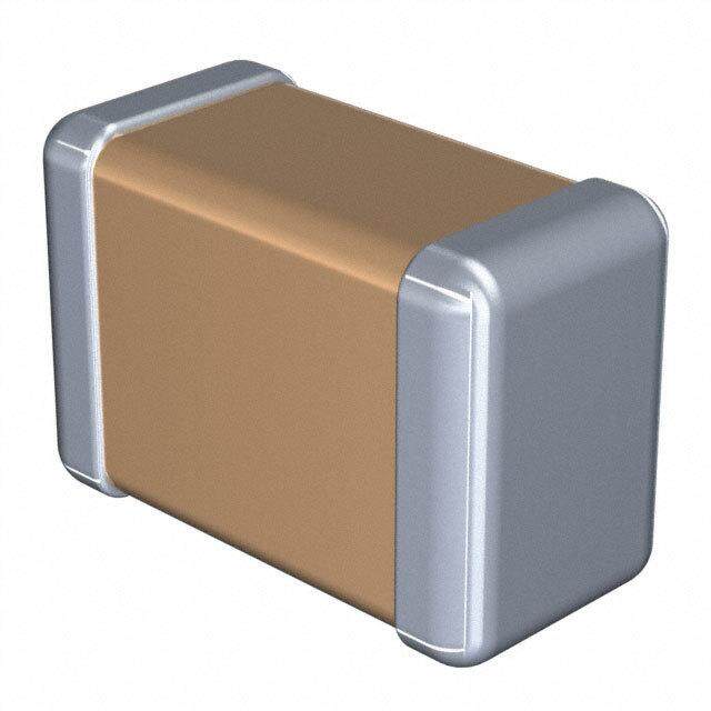
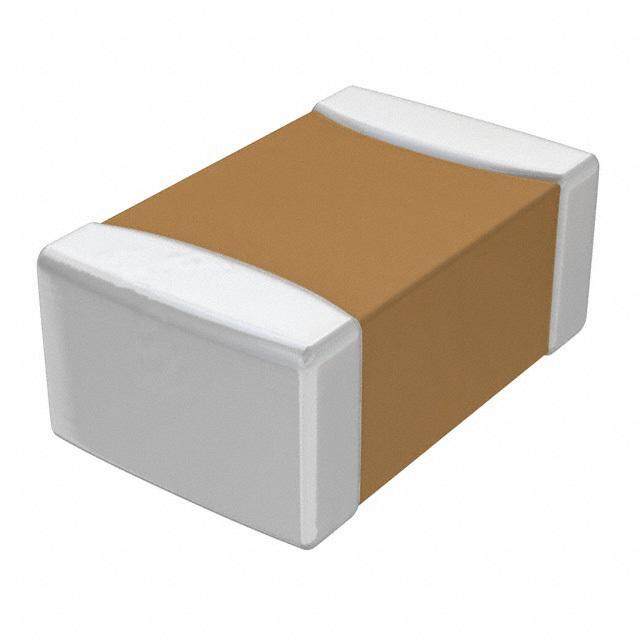
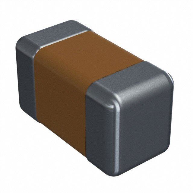
ICGOO电子元器件商城为您提供101X18W104MV4E由Johanson Dielectrics Inc.设计生产,在icgoo商城现货销售,并且可以通过原厂、代理商等渠道进行代购。 101X18W104MV4E价格参考¥1.25-¥5.47。Johanson Dielectrics Inc.101X18W104MV4E封装/规格:陶瓷电容器, 0.1µF ±20% 100V 陶瓷电容器 X7R 1206(3216 公制)。您可以下载101X18W104MV4E参考资料、Datasheet数据手册功能说明书,资料中有101X18W104MV4E 详细功能的应用电路图电压和使用方法及教程。
Johanson Dielectrics Inc.生产的型号为101X18W104MV4E的陶瓷电容器,主要应用于高频、高可靠性和高性能要求的电子设备中。该型号电容器具有以下特点和应用场景:

 1. 射频(RF)电路
   该电容器适用于射频电路中的滤波、耦合和旁路等应用。其低ESR(等效串联电阻)和低ESL(等效串联电感)特性使其在高频环境下表现出色,能够有效抑制噪声和干扰,确保信号的纯净传输。常见的应用包括无线通信设备、基站、卫星通信系统等。

 2. 微波通信
   在微波通信领域,101X18W104MV4E电容器可以用于频率合成器、振荡器和功率放大器等关键组件中。它能够在高频率下保持稳定的电容值,并且具有良好的温度系数,能够在极端温度环境下稳定工作,适用于航空航天、雷达系统等对可靠性要求极高的场合。

 3. 电源管理
   该电容器也可以用于电源管理电路中,特别是在需要高频开关电源的应用中。它可以作为输出滤波电容,帮助平滑电压波动,减少纹波,提高电源系统的稳定性。此外,它还可以用于DC-DC转换器中的耦合和去耦,确保电源的高效性和可靠性。

 4. 医疗设备
   在医疗设备中,尤其是涉及到高频信号处理或精密测量的设备,如超声波仪器、心电图机等,101X18W104MV4E电容器可以提供稳定的性能,确保设备的准确性和安全性。其高可靠性和长寿命也使得它适合用于长期运行的医疗设备中。

 5. 工业自动化
   在工业自动化控制系统中,尤其是在涉及高频信号传输或电磁兼容性要求较高的环境中,该电容器可以用于抗干扰设计,确保系统的稳定性和可靠性。例如,在机器人控制、传感器网络等应用中,它可以有效地滤除噪声,保证信号的完整性。

总之,Johanson Dielectrics Inc.的101X18W104MV4E陶瓷电容器凭借其优异的高频性能、高可靠性和稳定性,广泛应用于通信、医疗、工业自动化等领域,特别适合对性能和可靠性有严格要求的高端应用。
| 参数 | 数值 |
| 产品目录 | |
| 描述 | CAP CER 0.1UF 100V 20% X7R 1206多层陶瓷电容器MLCC - SMD/SMT 100volts 0.1uF 20% X7R |
| 产品分类 | |
| 品牌 | Johanson Dielectrics Inc |
| 产品手册 | |
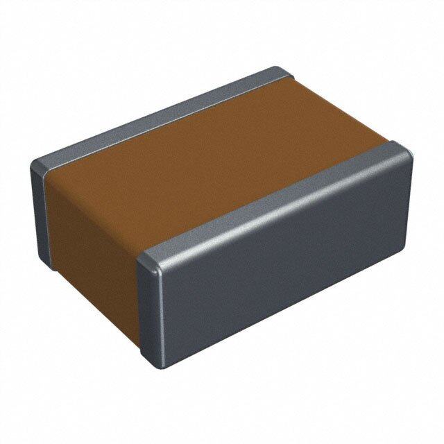
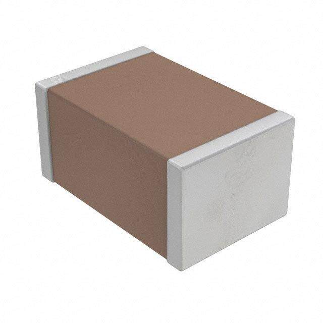
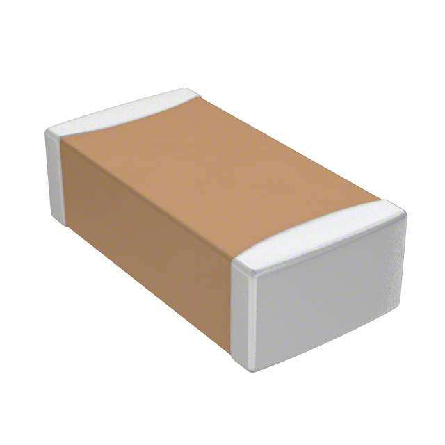
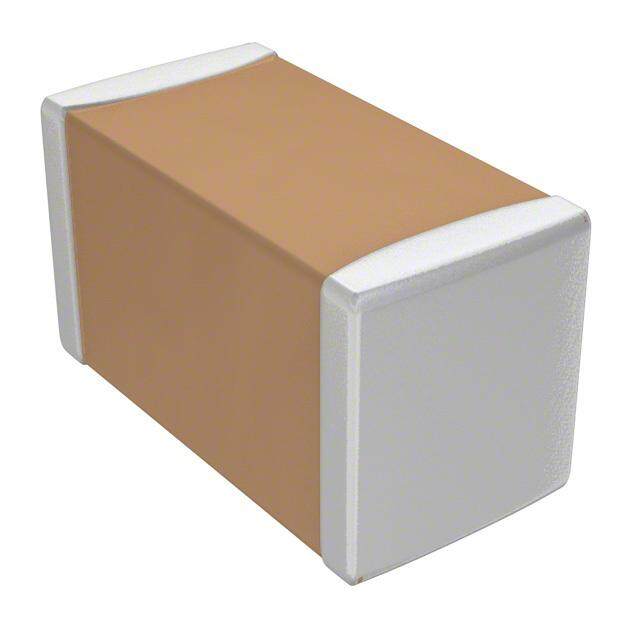
| 产品图片 |
|
| rohs | 符合RoHS无铅 / 符合限制有害物质指令(RoHS)规范要求 |
| 产品系列 | MLCC,多层陶瓷电容器MLCC - SMD/SMT,Johanson Dielectrics 101X18W104MV4EX2Y® |
| 数据手册 | |
| 产品型号 | 101X18W104MV4E |
| 产品 | Safety Certified MLCCs |
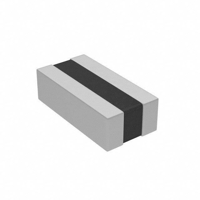
| 产品目录绘图 |
|
| 产品目录页面 | |
| 产品种类 | 多层陶瓷电容器MLCC - SMD/SMT |
| 其它名称 | 709-1342-1 |
| 包装 | 剪切带 (CT) |
| 厚度(最大值) | 0.050"(1.27mm) |
| 商标 | Johanson Dielectrics |
| 外壳代码-in | 1206 |
| 外壳代码-mm | 3216 |
| 外壳宽度 | 1.6 mm |
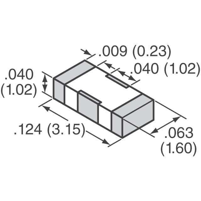
| 外壳长度 | 3.15 mm |
| 外壳高度 | 1.27 mm |
| 大小/尺寸 | 0.124" 长 x 0.063" 宽(3.15mm x 1.60mm) |
| 安装类型 | 表面贴装,MLCC |
| 容差 | ±20% |
| 封装 | Reel |
| 封装/外壳 | 1206(3216 公制) |
| 封装/箱体 | 1206 (3216 metric) |
| 工作温度 | -55°C ~ 125°C |
| 工作温度范围 | - 55 C to + 125 C |
| 工具箱 | /product-detail/zh/S-X2Y-MTR/709-1346-ND/2327212 |
| 工厂包装数量 | 3000 |
| 应用 | 旁通,去耦 |
| 引线形式 | - |
| 引线间距 | - |
| 最大工作温度 | + 125 C |
| 最小工作温度 | - 55 C |
| 标准包装 | 1 |
| 温度系数 | X7R |
| 温度系数/代码 | +/- 15 % |
| 特性 | 低 ESL 型(X2Y) |
| 电介质 | X7R |
| 电压-额定 | 100V |
| 电压额定值 | 100 V |
| 电压额定值DC | 100 V |
| 电容 | 0.1µF |
| 端接类型 | SMD/SMT |
| 等级 | - |
| 类型 | X2Y Filtering and Decoupling Capacitor MLCCs |
| 系列 | X18 |
| 高度-安装(最大值) | - |


- 商务部:美国ITC正式对集成电路等产品启动337调查
- 曝三星4nm工艺存在良率问题 高通将骁龙8 Gen1或转产台积电
- 太阳诱电将投资9.5亿元在常州建新厂生产MLCC 预计2023年完工
- 英特尔发布欧洲新工厂建设计划 深化IDM 2.0 战略
- 台积电先进制程称霸业界 有大客户加持明年业绩稳了
- 达到5530亿美元!SIA预计今年全球半导体销售额将创下新高
- 英特尔拟将自动驾驶子公司Mobileye上市 估值或超500亿美元
- 三星加码芯片和SET,合并消费电子和移动部门,撤换高东真等 CEO
- 三星电子宣布重大人事变动 还合并消费电子和移动部门
- 海关总署:前11个月进口集成电路产品价值2.52万亿元 增长14.8%


PDF Datasheet 数据手册内容提取
X2Y® F & D C ILTER ECOUPLING APACITORS X2Y® filter capacitors employ a unique, patented low inductance design featuring two balanced capacitors that are immune to temperature, voltage and aging performance differences. These components offer superior decoupling and EMI filtering performance, virtually eliminate parasitics, and can replace multiple capacitors and inductors saving board space and reducing assembly costs. ADVANTAGES APPLICATIONS • One device for EMI suppression or decoupling • Amplifier Filter & Decoupling • Replace up to 7 components with one X2Y • High Speed Data Filtering • Differential and common mode attenuation • EMC I/O Filtering • Matched capacitance line to ground, both lines • FPGA / ASIC / µ-P Decoupling • Low inductance due to cancellation effect • DDR Memory Decoupling EM(1 IY F-iCltaepri.n)g <10pF 10pF 22pF 27pF 33pF 47pF 100pF 220pF 470pF 1000pF 1500pF 2200pF 4700pF .010µF .015µF .022µF .039µF .047µF 0.10µF 0.18µF 0.22µF 0.33µF 0.40µF 0.47µF 1.0µF Po(2w Ye-rC Bayppsa.)ss <20pF 20pF 44pF 54pF 66pF 94pF 200pF 440pF 940pF 2000pF 3000pF 4400pF 9400pF .020µF .030µF .044µF .078µF .094µF 0.20µF 0.36µF 0.44µF 0.66µF 0.80µF 0.94µF 2.0µF SIZE CAP. CODE XRX 100 220 270 330 470 101 221 471 102 152 222 472 103 153 223 393 473 104 184 224 334 404 474 105 NP0 50 50 50 50 50 50 50 0402 (X07) X7R 50 50 50 50 50 50 16 NP0 100 100 100 100 100 50 50 50 0603 (X14) X7R 100 100 100 100 100 100 100 100 50 25 25 16 10 10 NP0 100 100 100 100 100 100 100 50 0805 (X15) X7R 100 100 100 100 100 100 100 100 50 50 50 25 NP0 VOLTAGE 100 1206 (X18 RATINGS X7R 6.3 = 6.3 VDC 100 100 100 100 100 16 16 10 10 = 10 VDC 1210 (X41) X7R 16 = 16 VDC 500 100 100 100 25 16 25 = 25 VDC 1410 (X44) X7R 50 = 50 VDC 500 100 100 = 100 VDC 1812 (X43) X7R 500 = 500 VDC 500 100 Contact factory for part combinations not shown. Filtering capacitance is specified as Line-to-Ground ( Terminal A or B to G) Power Bypass capacitance is specified Power-to-Ground (A + B to G) Rated voltage is from line to ground in Circuit 1, power to ground in Circuit 2 . HOW TO ORDER X2Y® CAPACITORS P/N written: 101X14W102MV4T 100 X14 W 102 M V 4 T +AQ VOLTAGE SIZE DIELECTRIC CAPACITANCE TOLERANCE TERMINATION MARKING PACKING QUALIFICATION 6R3 = 6.3 V X07 = 0402 N = NP0 1st two digits are M = ± 20% V = NI Barrier with 4 = Unmarked E = Embossed 7” AEC-Q200 100 = 10 V X14 = 0603 W = X7R significant; third digit * D = ± 0.50 pF 100% Tin Plating T = Punched 7” Qualification * 160 = 16 V X15 = 0805 denotes number of (Matte) (Not available) (optional) 250 = 25 V X18 = 1206 zeros, R = decimal. *Values < 10 pF No code = bulk 510001 == 5100 0V V XX4414 == 11241100 110024 == 100.1000 µpFF only flexFi b=le Pteorlmytienramti o n pTear pEeIA s RpeSc4s8.1 501 = 500 V X43 = 1812 5R6 = 5.6pF T = SnPb X2Y® technology patents and registered trademark under license from X2Y ATTENUATORS, LLC 10 www.johansondielectrics.com
X2Y® F & D C ILTER ECOUPLING APACITORS EMI Filtering Scc21 Power Bypass S21 Labeled capacitance values below follow the P/N order code (single Y cap value) Effective capacitance measured in Circuit 2 is 2X of the labled single Y cap value. 10.0Ω 10.0Ω Ω) Ω) 1.00Ω mpedance ( 1.00Ω mpedance ( mate I 0.10Ω mate I 0.10Ω Approxi Approxi 0.01Ω 0.01Ω More data at https://s21plotter.johansondielectrics.com/ ELECTRICAL CHARACTERISTICS NP0 X7R TEMPERATURE COEFFICIENT: 0±30ppm/°C (-55 to +125°C) ±15% (-55 to +125°C) Vrated ≤100VDC: DWV = 2.5 X WVDC, 25°C, 50mA max. DIELECTRIC STRENGTH: Vrated = 500VDC: DWV = 1.5 X WVDC, 25°C, 50mA max. WVDC ≥ 50 VDC: 2.5% max. WVDC = 25 VDC: 3.5% max. DISSIPATION FACTOR: 0.1% max. WVDC = 10-16 VDC: 5.0% max. WVDC = 6.3 VDC: 10% max. INSULATION RESISTANCE C≤ 0.047µF: 1000 ΩF or 100 GΩ, whichever is less (MIN. @ 25°C, WVDC) C> 0.047µF: 500 ΩF or 10 GΩ, whichever is less C > 100 pF; 1kHz ±50Hz; 1.0±0.2 VRMS TEST CONDITIONS: 1.0kHz±50Hz @ 1.0±0.2 Vrms C ≤ 100 pF; 1Mhz ±50kHz; 1.0±0.2 VRMS CB OTHER: See page 79 for additional dielectric specifications. W Cross-sectional View Dimensional View G CB EB A B W T L G CASE SIZE EB 0402 (X07) 0603 (X14) 0805 (X15) 1206 (X18) 1T210 (X41) 1410 (X44) 1812 (X43) IN MM IN MM IN MM IN M LM IN MM IN MM IN MM 0.045 ± 1.143 ± 0.064 ± 1.626 ± 0.080 ± 2.032 ± 0.124 ± 3.150 ± 0.125 ± 3.175 ± 0.140 ± 3.556 ± 0.174 ± 4.420 ± L 0.003 0.076 0.005 0.127 0.008 0.203 0.010 0.254 0.010 0.254 0.010 0.254 0.010 0.254 0.025 ± 0.635 ± 0.035 ± 0.889 ± 0.050 ± 1.270 ± 0.063 ± 1.600 ± 0.098 ± 2.489 ± 0.098 ± 2.490 ± 0.125 ± 3.175 ± W 0.003 0.076 0.005 0.127 0.008 0.203 0.010 0.254 0.010 0.254 0.010 0.254 0.010 0.254 0.020 0.508 0.026 0.660 0.040 1.016 0.050 1.270 0.070 1.778 0.070 1.778 0.090 2.286 T max max max max max max max max max max max max max max 0.008 ± 0.203 ± 0.010 ± 0.254 ± 0.012 ± 0.305 ± 0.016 ± 0.406 ± 0.018 ± 0.457 ± 0.018 ± 0.457 ± 0.022 ± 0.559 ± EB 0.003 0.076 0.006 0.152 0.008 0.203 0.010 0.254 0.010 0.254 0.010 0.254 0.012 0.305 0.012 ± 0.305 ± 0.018 ± 0.457 ± 0.022 ± 0.559 ± 0.040 ± 1.016 ± 0.045 ± 1.143 ± 0.045 ± 1.143 ± 0.045 ± 1.143 ± CB 0.003 0.076 0.004 0.102 0.005 0.127 0.005 0.127 0.005 0.127 0.005 0.127 0.005 0.127 www.johansondielectrics.com 11
X2Y® F & D C ILTER ECOUPLING APACITORS THE X2Y® DESIGN - A BALANCED, LOW ESL, “CAPACITOR CIRCUIT” The X2Y® capacitor design starts with standard 2 terminal MLC capacitor’s opposing electrode sets, A & B, and adds a third electrode set (G) which surround each A & B electrode. The result is a highly vesatile three node capacitive circuit containing two tightly matched, low inductance capacitors in a compact, four-terminal SMT chip. EMI FILTERING: The X2Y® component contains two shunt or “line-to-ground” Y capacitors. Ultra-low ESL (equivalent series inductance) and tightly matched inductance of these capacitors provides unequaled high frequency Common-Mode noise filtering with low noise mode conversion. X2Y® components reduce EMI emissions far better than unbalanced discrete shunt capacitors or series inductive filters. Differential signal loss is determined by the cut off frequency of the single line-to-ground (Y) capacitor value of an X2Y®. POWER BYPASS / DECOUPLING For Power Bypass applications, X2Ys® two “Y” capacitors are connected in parallel. This doubles the total capacitance and reduces their mounted inductance by 80% or 1/5th the mounted inductance of similar sized MLC capacitors enabling high-performance bypass networks with far fewer components and vias. Low ESL delivers improved High Frequency performance into the GHz range. GSM RFI ATTENUATION IN AUDIO & ANALOG GSM handsets transmit in the 850 and 1850 MHz bands using a TDMA pulse rate of 217Hz. These signals cause the GSM buzz heard in a wide range of audio products from headphones to concert hall PA systems or “silent” signal errors created in medical, industrial process control, and security applications. Testing was conducted where an 840MHz GSM handset signal was delivered to the inputs of three different amplifier test circuit configurations shown below whose outputs were measured on a HF spectrum analyzer. 1) No input filter, 2 discrete MLC 100nF power bypass caps. 2) 2 discrete MLC 1nF input filter, 2 discrete MLC 100nF power bypass caps. 3) A single X2Y 1nF input filter, a single X2Y 100nF power bypass cap. X2Y configuration provided a nearly flat response above the ambient and up to 10 dB imrpoved rejection than the conventional MLCC configuration. AMPLIFIER INPUT FILTER EXAMPLE In this example, a single Johanson X2Y® component was used to filter noise at the input of a DC instrumentation amplifier. This reduced component count by 3-to-1 and costs by over 70% vs. conventional filter components that included 1% film Y-capacitors. Parameter X2Y® Discrete Comments 10nF 10nF, 2 @ 220 pF DC offset shift < 0.1 µV < 0.1 µV Referred to input Common mode rejection 91 dB 92 dB Source: Analog Devices, “A Designer’s Guide to Instrumentation Amplifiers (2nd Edition)” by Charles Kitchin and Lew Counts 12 www.johansondielectrics.com
X2Y® F & D C ILTER ECOUPLING APACITORS COMMON MODE CHOKE REPLACEMENT Measured Common Mode Rejection • Superior High Frequency Emissions Reduction • Smaller Sizes, Lighter Weight • No Current Limitation • Vibration Resistant • No Saturation Concerns See our website for a detailed application note with component test comparisons and circuit emissions measurements. PARALLEL CAPACITOR SOLUTION A common design practice is to parallel decade capacitance values to extend the high frequency performance of the filter network. This causes an unintended and often over-looked effect of anti-resonant peaks in the filter networks combined impedance. X2Y’s very low mounted inductance allows designers to use a single, higher value part and completely avoid the anti- resonance problem. The impedance graph on right shows the combined mounted impedance of a 1nF, 10nF & 100nF 0402 MLC in parrallel in RED. The MLC networks anti-resonance peaks are nearly 10 times the desired impedance. A 100nF and 47nF X2Y are plotted in BLUE and GREEN. (The total capacitance of X2Y (Circuit 2) is twice the value, or 200nF and 98nF in this example.) The sigle X2Y is clearly superior to the three paralleled MLCs. X2Y HIGH PERFORMANCE POWER BYPASS - IMPROVE PERFORMANCE, REDUCE SPACE & VIAS Actual measured performance of two high performance SerDes FPGA designs demonstrate how a 13 component X2Y bypass network significantly out performs a 38 component MLC network. For more information see https://johansondielectrics.com/downloads/JDI_X2Y_STXII.pdf www.johansondielectrics.com 13