ICGOO在线商城 > 10-037324-014

 Datasheet下载
- 型号: 10-037324-014
- 制造商: Amphenol
- 库位|库存: xxxx|xxxx
- 要求:
| 数量阶梯 | 香港交货 | 国内含税 |
| +xxxx | $xxxx | ¥xxxx |
查看当月历史价格
查看今年历史价格


- 商务部:美国ITC正式对集成电路等产品启动337调查
- 曝三星4nm工艺存在良率问题 高通将骁龙8 Gen1或转产台积电
- 太阳诱电将投资9.5亿元在常州建新厂生产MLCC 预计2023年完工
- 英特尔发布欧洲新工厂建设计划 深化IDM 2.0 战略
- 台积电先进制程称霸业界 有大客户加持明年业绩稳了
- 达到5530亿美元!SIA预计今年全球半导体销售额将创下新高
- 英特尔拟将自动驾驶子公司Mobileye上市 估值或超500亿美元
- 三星加码芯片和SET,合并消费电子和移动部门,撤换高东真等 CEO
- 三星电子宣布重大人事变动 还合并消费电子和移动部门
- 海关总署:前11个月进口集成电路产品价值2.52万亿元 增长14.8%


PDF Datasheet 数据手册内容提取
Amphenol ® QWL Series Cylindrical Connectors 12-053-4 Amphenol
TABLE OF CONTENTS Description Page Description...............................................................Page Amphenol® Heavy Duty Cylindrical Connectors QWL - accessories QWL Series ......................................................... 2 10-130380 cable sealing adapter (with clamp bars) .......................................... 43, 44 QWL the environmental connector ............................... 3 QWL - accessories 10-10133X cable sealing adapters ................ 45-48 QWL how to order ..................................................... 4, 5 QWL - accessories 10-113637 cable sealing adapter (with woven QWL strain relief) ....................................................49-52 10-1070 wall mount receptacle ............................ 6 QWL - accessories QWL adapter, cable clamp .......................................... 53 10-1071 cable connecting plug ............................ 7 QWL - accessories QWL adapter, cable clamp, sealing plugs .............. 54-56 10-1072 box mount receptacle ............................ 8 QWL - accessories QWL protection caps ............................................. 57, 58 10-1073 jam nut receptacle (wall mount) ............. 9 QWL - accessories QWL flange gasket, grip banding clamp ...................... 59 10-1074 thru bulkhead receptacle ..................... 10 QWL QWL crimp contacts .................................................... 60 10-1076 straight plug ......................................... 11 QWL QWL solder contacts ................................................... 61 10-1077 flange mount plug ................................ 12 QWL QWL application tools (crimp type)...............................62 10-1079 jam nut receptacle (box mount) ........... 13 QWL QWL thermocouple contacts insert arrangements and arrangements ......................................... 63-69 selection guide .............................................. 14-16 Other Heavy Duty Connectors Offered by QWL Amphenol.............................................................70 alternate positioning........................................... 17 Sales Office Listing QWL contact insert arrangements ......................... 18-29 QWL special contact insert arrangements ............. 30-40 For additional information concerning the QWL - accessories Amphenol® QWL Series Cylindrical Connector, or if cabling information ...................................... 41, 42 there are special application requirements, contact your local sales office or Amphenol Corporation Amphenol Aerospace 40-60 Delaware Ave. Sidney, New York 13838-1395 Telephone: 607-563-5011 Fax: 607-563-5351 Amphenol Aerospace operates Quality Systems www.amphenol-aerospace.com that are Certified to ISO-9001 and AS-9100 by third (Most Amphenol catalogs can be viewed, printed party Registrars. and down-loaded from the website) 1
Amphenol® Heavy Duty Cylindrical Connectors QWL Series Amphenol® QWL Series Connec- tors are tailor made for compact, heavy duty industrial use. The outstanding performance of this series makes it well suited for ship- board installations and ground sup- port power distribution applications where physical strength and depend- ability are key requirements. wall mount receptacle thru bulkhead receptacle The QWL Series are a versatile, economical alternative to military qualified designs. Equivalent MS shell sizes and insert arrangements offer compatibility with all standard cable types. MIL-C-22992 environmental connector require- ments (see page 1) are used as a per- formance criteria base for this series to assure reliability under the most severe conditions. straight plug cable connecting plug The design features of this connec- tor series provide: • Exceptional Service - high strength aluminum shells with Alu- milite 225* hard anodic finish and shock resistant resilient inserts. • Foolproof Operation - rugged double stub coupling threads, left hand accessory threads and sim- ple single keyway mating. box mount receptacle flange mount plug • Versatility - both MS and custom insert patterns available for a wide variety of multiconductor cables. A complete line of accessories is available for use with QWL Series connectors, including cable sealing and clamp adapters, protective cov- ers, flange gaskets and banding clamps. jam nut receptacle jam nut receptacle (wall mount) (box mount) * Registered trademark of Aluminum Company of America 2
QWL the environmental connector •• HHIIGGHH CCUURRRREENNTT CCAAPPAACCIITTYY ffoorr ppoowweerr ddiissttrriibbuuttiioonn nneettwwoorrkk aanndd iinnppuuttss ttoo llaarrggee eeqquuiippmmeenntt •• RRUUGGGGEEDD CCOONNSSTTRRUUCCTTIIOONN ddiiccttaatteedd bbyy tthhee wwoorrkkiinngg eennvviirroonnmmeenntt,, hhiigghh ssttrreennggtthh aalluummiinnuumm sshheellllss wwiitthh AAlluummiilliittee 222255** hhaarrdd aannooddiicc ffiinniisshh,, sshhoocckk rreessiiss-- ttaanntt rreessiilliieenntt iinnsseerrttss,, ggaasskkeettss oorr ““OO”” rriinnggss aatt aapppprroopprriiaattee ssuurrffaacceess ffoorr ppeerrffeecctt wweeaatthheerr ttiigghhtt ccoonnnneeccttiioonnss.. •• SSEERRVVIICCEEAABBIILLIITTYY AANNDD FFOOOOLL--PPRROOOOFF OOPPEERRAATTIIOONN wwiitthh ffaasstt ccoouupplliinngg,, eeaassiillyy mmaaiinnttaaiinneedd ddoouubbllee ssttuubb tthhrreeaaddss,, lleefftt hhaanndd aacccceessssoorryy tthhrreeaaddss aanndd ssiinnggllee kkeeyywwaayy mmaattiinngg.. •• VVEERRSSAATTIILLIITTYY -- bbootthh MMSS aanndd ccuussttoomm iinnsseerrtt ppaatttteerrnnss aavvaaiillaabbllee ttoo aaccccoommmmoo-- ddaattee aa wwiiddee vvaarriieettyy ooff mmuullttii ccoonndduuccttoorr ccaabblleess.. CONDITION CONFIGURATION DESCRIPTION REFERENCE THERMAL UNMATED Five complete one hour temperature MIL-STD-1344 SHOCK cycles of –55°C to +125°C method 1003 test condition MOISTURE MATED Ten complete 24 hour cycles of MIL-STD-202 RESISTANCE +25°C to +65°C temperature at 90% method 106 (Cable mounted to 98% humidity connectors) DURABILITY MATED 500 complete mating/unmating cycles MIL-C-22992 SALT SPRAY UNMATED 48 hour exposure to atomized 5% MIL-STD-1344 (Corrosion) saline solution at +35°C method 1001 VIBRATION MATED 10 to 55 Hz, .06 inch total excursion MIL-STD-1344 in 1 minute cycles for 6 hours method 2005 55 to 2000 Hz, 10G peak amplitude sweep HIGH IMPACT MATED Nine hammer blows from 1, 3 and MIL-STD-202 5 feet, three each in three axes method 207 on mounting panel FLUID UNMATED 20 hours immersion in hydraulic MIL-C-22992 IMMERSION fluid and lubricating oil WATER MATED 4 hours immersion at 1 atmosphere MIL-C-22992 IMMERSION pressure differential * Registered trademark of Aluminum Company of America 3
QWL how to order QWL heavy duty cylindrical connectors are ordered by Amphenol® part number only. To illustrate the ordering procedure, part number 10-107628-5P is shown as follows: PART NUMBER 10 - 107 6 28-5 P 1 2 3 4 5 See code below: 1. Base Number Prefix - used to define contact type and finish. 10- Solder type contacts, silver plated (Standard) 75- Crimp type contacts, silver plated 81- Crimp type contacts, plated .0001 gold over silver 82- Crimp type contacts for MIL-C-13777 cable, silver plated 83- Crimp type contacts for MIL-C-13777 cable, plated .0001 gold over silver 85- Crimp type contacts plated .00005 gold over silver 2. Base Number - QWL Series Heavy Duty Cylindrical Connector. 3. Shell Style - 0 designates wall mount receptacle 1 designates cable connecting plug 2 designates box mount receptacle 3 designates jam nut receptacle with rear accessory threads (wall mount) 4 designates thru bulkhead receptacle 6 designates straight plug 7 designates flange mount plug 9 designates jam nut receptacle (box mount) 4. Shell Size/Insert Arrangement - Amphenol® QWL connectors are available in equivalent MS shell sizes with all current MS insert arrangements as well as a large selection of special arrangements for power and signal circuits. Select the required insert arrangement number from those shown on pages 18-40. 5. Contact Type/Alternate Insert Rotations - P for pin, S for socket. When an alternate position of the connector insert is required to prevent cross mating of connectors, a different letter (other than P or S) is used. Select from the table below the Amphenol® letter which indicates both type of contact, and insert rotation desired. Refer to page 17 for alternate insert rotations. PIN CONTACTS SOCKET CONTACTS MS AMPHENOL® MS AMPHENOL® LETTERS LETTER LETTERS LETTER P P (normal) S S (normal) PW G SW H PX I SX J PY K SY L PZ M SZ N 4
QWL how to order, cont. ACCESSORIES Cable Sealing Adapters - these are the basic connector accessories which provide moisture proofing and cable strain relief. Selection is made on the basis of accessory style, shell size and cable dimensions. To illustrate the ordering proce- dure, part number 10-101335-361 is shown as follows: PART NUMBER 10 - 101335 - 361 1 2 See code below: 1. Accessory Base Number - refer to pages 41 through 52 for descriptions and dimensional data.10-101332 designates short barrel length with woven strain relief grip 10-101333 designates short barrel length without strain relief 10-101334 designates short barrel length with woven strain relief grip and attaching ring for protection cap with bead chain 10-101335 designates short barrel length with attaching ring for protection cap with bead chain 10-101380 designates short barrel length with attaching ring for protection cap with bead chain and clamp type strain relief bars 10-113637 designates long barrel length with woven strain relief and attaching ring for protection cap with bead chain 2. Part Number – represents connector shell size and range of cable diameters accommodated by the sealing adapter. Refer to the page listed below to determine the part number required for the accessory style being used: Accessory Series Page 10-10133X 46 - 48 10-130380 44 10-113637 50 - 52 Cable Clamp 10-749XX-( ) and Adapter 10-113196-XX Connectors which require weatherproofing on open wire cables are provided with a moisture seal by this cable clamp, a modification of the MS3057B design. A rubber grommet with holes for individual wires is used in place of the sleeve. As the assembly is tightened, the grommet is compressed around each wire, sealing out moisture. Order this clamp by the part number listed on page 53 to accommodate the connector being used. Suffix the part number with the connector insert arrangement number. To attach the cable clamp to the left hand accessory threads of QWL connectors, Adapter 10-113196-XX is needed. Finish is non-conductive Alumilite. Order by adapter part number listed on page 53 to accommodate the connector shell size being used. For a moisture proof seal, unused grommet holes must be filled with the appropriate size sealing plug or seal- ing rod selected from the table on page 53. Sealing plug or sealing rods must be ordered separately. M85049/1 Cable Clamp and Adapter 10-113138-XX - order this clamp by the M85049( )C part number listed on page 55 to accommodate the cable type being used. To attach the cable clamp to the left hand accessory threads of QWL connec- tors, Adapter 10-113138-XX is needed. Order by adapter part number listed on page 55 to accommodate the connector shell size being used. Standard finish on the clamp is olive drab, cadmium plate. Adapter finish is non-conductive Alumilite. MS3420-( )A sleeve, to facilitate sealing on smaller diameter cables, must be ordered separately. MS3420-( )A sleeves may be nested to accommodate smaller cable diameters. Plug Protection Caps - 10-101046-( ) designates plug cover with chain, Alumilite 225 finish 10-101531-( ) designates plug cover with chain and eyelet end, Alumilite 225 finish Order these plug covers by the part number listed on page 57 for the appropriate connector shell size. Receptacle Protection Caps - 10-101063-( ) designates receptacle cover with chain, Alumilite 225 finish 10-101048-( ) designates receptacle cover with chain and eyelet, Alumilite 225 finish Order these receptacle covers by the part number listed on page 57 for the appropriate connector shell size. Flange Gasket - 10-36675-( ) for operating temperature range –67° to +275°F 10-40450-( ) for operating temperature range 0° to +257°F Order by part number listed on page 59 for appropriate connector shell size. 10-183249 Grip Banding Clamp - order this stainless steel clamp by part number listed on page 59 to accommodate cable diameter being used. 5
QWL 10-1070XX wall mount receptacle K Z S R A M W THREAD S R T B V 4 HOLES LEFT HAND All dimensions for reference only. B T A Min M Dia V Part Shell Thread Full K +.016 R S +.004 Thread W Z Number* Size Class 2A Thread ±.015 –.000 ±.005 ±.020 –.003 Class 2A-LH ±.010 Max 10-107010 10S .6250-0.05P-0.1L-DS .391 .704 .562 .719 1.000 .150 .500-28UNEF .400 .450 10-107012 12S .7500-0.1P-0.2L-DS .391 .704 .562 .812 1.094 .150 .625-24UNEF .400 .450 10-107013 12 .7500-0.1P-0.2L-DS .625 .891 .750 .812 1.094 .150 .625-24UNEF .588 .700 10-107014 14S .8750-0.1P-0.2L-DS .391 .704 .562 .906 1.188 .150 .750-20UNEF .400 .450 10-107015 14 .8750-0.1P-0.2L-DS .625 .891 .750 .906 1.188 .150 .750-20UNEF .588 .700 10-107016 16S 1.0000-0.1P-0.2L-DS .391 .704 .562 .969 1.281 .150 .875-20UNEF .400 .450 10-107017 16 1.0000-0.1P-0.2L-DS .625 .891 .750 .969 1.281 .150 .875-20UNEF .588 .700 10-107018 18 1.1250-0.1P-0.2L-DS .625 .906 .750 1.062 1.375 .177 1.000-20UNEF .573 .686 10-107020 20 1.2500-0.1P-0.2L-DS .625 .906 .750 1.156 1.500 .177 1.125-18NEF .573 .686 10-107022 22 1.3750-0.1P-0.2L-DS .625 .906 .750 1.250 1.625 .177 1.250-18NEF .573 .686 10-107024 24 1.5000-0.1P-0.2L-DS .625 .968 .812 1.375 1.750 .177 1.375-18NEF .573 .624 10-107028 28 1.7500-0.1P-0.2L-DS .625 .968 .812 1.562 2.000 .177 1.625-18NEF .573 .624 10-107032 32 2.0000-0.1P-0.2L-DS .625 1.031 .875 1.750 2.250 .209 1.875-16N .573 .561 10-107036 36 2.2500-0.1P-0.2L-DS .625 1.031 .875 1.938 2.500 .209 2.0625-16N .573 .561 10-107040 40 2.5000-0.1P-0.2L-DS .625 1.031 .875 2.188 2.750 .209 2.3125-16N .573 .561 10-107044 44 2.7500-0.1P-0.2L-DS .625 1.031 .875 2.375 3.000 .209 2.625-16UN .698 .801 *For complete order number see page 4 6
QWL 10-1071XX cable connecting plug S K Z M W A Thread S V LEFT HAND All dimensions for reference only. A Thread M V Part Shell (plated) K +.016 S Thread W Z Number* Size Class 2A ±.015 –.000 ±.020 Class 2A-LH ±.010 Max 10-107110 10S .6250-0.05P-0.1L-DS .704 .453 .750 .500-28UNEF .400 .450 10-107112 12S .7500-0.1P-0.2L-DS .704 .453 .875 .625-24UNEF .400 .450 10-107113 12 .7500-0.1P-0.2L-DS .891 .641 .875 .625-24UNEF .588 .701 10-107114 14S .8750-0.1P-0.2L-DS .704 .453 1.000 .750-20UNEF .400 .450 10-107115 14 .8750-0.1P-0.2L-DS .891 .641 1.000 .750-20UNEF .588 .701 10-107116 16S 1.0000-0.1P-0.2L-DS .704 .453 1.094 .875-20UNEF .400 .450 10-107117 16 1.0000-0.1P-0.2L-DS .891 .641 1.094 .875-20UNEF .588 .701 10-107118 18 1.1250-0.1P-0.2L-DS .906 .656 1.281 1.000-20UNEF .573 .686 10-107120 20 1.2500-0.1P-0.2L-DS .906 .656 1.375 1.125-18UNEF .573 .686 10-107122 22 1.3750-0.1P-0.2L-DS .906 .656 1.500 1.250-18UNEF .573 .686 10-107124 24 1.5000-0.1P-0.2L-DS .968 .719 1.625 1.375-18UNEF .573 .624 10-107128 28 1.7500-0.1P-0.2L-DS .968 .719 1.875 1.625-18UNEF .573 .624 10-107132 32 2.0000-0.1P-0.2L-DS 1.031 .656 2.125 1.875-16UN .573 .561 10-107136 36 2.2500-0.1P-0.2L-DS 1.031 .656 2.375 2.0625-16UNS .573 .561 10-107140 40 2.5000-0.1P-0.2L-DS 1.031 .656 2.625 2.3125-16UNS .573 .561 10-107144 44 2.7500-0.1P-0.2L-DS 1.031 .656 3.000 2.625-16UN .698 .800 10-107148 48 3.0000-0.1P-0.2L-DS 1.031 .656 3.125 2.875-16UN .698 .800 *For complete order number see page 4 7
QWL 10-1072XX box mount receptacle K Z S R M W S R Y T 4 HOLES B A All dimensions for reference only. A B T Thread Min K M Dia W Y Part Shell (Plated) Full +.026 +.016 R S +.004 +.020 Dia Z Number* Size Class 2A Thread –.010 –.000 ±.005 ±.020 –.003 –.036 ±.010 Max 10-107210 10S .6250-0.05P-0.1L-DS .391 .703 .562 .719 1.000 .150 .281 .469 .451 10-107212 12S .7500-0.1P-0.2L-DS .391 .703 .562 .812 1.094 .150 .281 .594 .451 10-107213 12 .7500-0.1P-0.2L-DS .625 .891 .750 .812 1.094 .150 .469 .594 .700 10-107214 14S .8750-0.1P-0.2L-DS .391 .703 .562 .906 1.188 .150 .281 .719 .451 10-107215 14 .8750-0.1P-0.2L-DS .625 .891 .750 .906 1.188 .150 .469 .719 .700 10-107216 16S 1.0000-0.1P-0.2L-DS .391 .703 .562 .969 1.281 .150 .281 .844 .451 10-107217 16 1.0000-0.1P-0.2L-DS .625 .891 .750 .969 1.281 .150 .469 .844 .700 10-107218 18 1.1250-0.1P-0.2L-DS .625 .906 .750 1.062 1.375 .177 .453 .969 .686 10-107220 20 1.2500-0.1P-0.2L-DS .625 .906 .750 1.156 1.500 .177 .453 1.125 .686 10-107222 22 1.3750-0.1P-0.2L-DS .625 .906 .750 1.250 1.625 .177 .453 1.250 .686 10-107224 24 1.5000-0.1P-0.2L-DS .625 1.000 .812 1.375 1.750 .177 .359 1.375 .585 10-107228 28 1.7500-0.1P-0.2L-DS .625 1.000 .812 1.562 2.000 .177 .359 1.594 .591 10-107232 32 2.0000-0.1P-0.2L-DS .625 1.063 .875 1.750 2.250 .209 .296 1.844 .528 10-107236 36 2.2500-0.1P-0.2L-DS .625 1.063 .875 1.938 2.500 .209 .296 2.031 .528 10-107240 40 2.5000-0.1P-0.2L-DS .625 1.063 .875 2.188 2.750 .209 .296 2.281 .528 10-107244 44 2.7500-0.1P-0.2L-DS .625 1.063 .875 2.375 3.000 .209 .546 2.562 .769 10-107248 48 3.0000-0.1P-0.2L-DS .625 1.063 .875 2.625 3.250 .209 .546 2.812 .769 *For complete order number see page 4 8
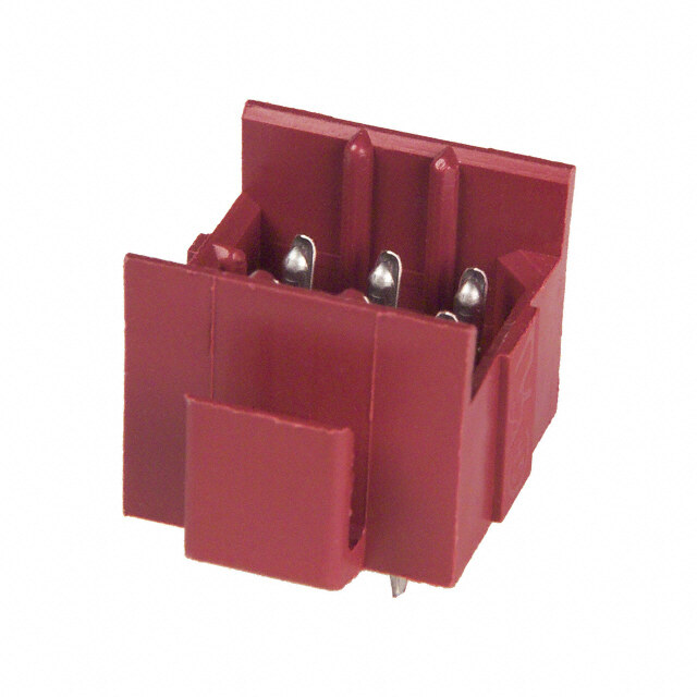
QWL 10-1073XX jam nut receptacle (wall mount) S F M N P A H Z P S V B E W LEFT HAND mounting dimensions K Dia Shell +.005 G U U Size –.000 ±.003 ±.005 10 .880 .518 .625 G .D1I2A5. ±P.I0N02 12, 13 1.005 .562 .688 14, 15 1.130 .606 .750 16, 17 1.255 .699 .875 18 1.380 .739 .938 G U 20 1.505 .783 1.000 22 1.630 .830 1.062 24 1.880 .919 1.188 28 2.130 1.007 1.312 32 2.380 1.096 1.438 K 36 2.630 1.183 1.562 40 2.880 1.292 1.703 All dimensions for reference only. H F Panel V Part Shell A Thread B E Thread Hex Thickness M N P S Thread W Z Number* Size Class 2A ±.010 Class 2A ±.010 Min Max ±.010 ±.015 ±.010 ±.010 Class 2A-LH ±.010 Max 10-107310 10S .6250-0.5-0.1L-DS .385 .6875-24UNEF .875 .094 .227 .844 .469 .375 1.062 .500-28UNEF .344 .295 10-107312 12S .7500-0.1P-0.2L-DS .385 .875-20UNEF 1.062 .094 .200 .906 .469 .442 1.250 .625-24UNEF .344 .232 10-107313 12 .7500-0.1P-0.2L-DS .585 .875-20UNEF 1.062 .094 .188 1.094 .641 .442 1.250 .625-24UNEF .516 .483 10-107314 14S .8750-0.1P-0.2L-DS .385 1.000-20UNEF 1.250 .094 .200 .906 .469 .486 1.376 .750-20UNEF .344 .232 10-107315 14 .8750-0.1P-0.2L-DS .585 1.000-20UNEF 1.250 .094 .188 1.094 .641 .486 1.376 .750-20UNEF .516 .483 10-107316 16S 1.0000-0.1P-0.2L-DS .385 1.125-18UNEF 1.312 .094 .200 .906 .469 .530 1.500 .875-20UNEF .344 .232 10-107317 16 1.0000-0.1P-0.2L-DS .585 1.125-18UNEF 1.312 .094 .188 1.094 .641 .530 1.500 .875-20UNEF .516 .483 10-107318 18 1.1250-0.1P-0.2L-DS .585 1.250-18UNEF 1.500 .094 .203 1.109 .704 .623 1.750 1.000-20UNEF .516 .467 10-107320 20 1.2500-0.1P-0.2L-DS .585 1.375-18UNEF 1.562 .094 .203 1.109 .704 .663 1.875 1.125-18UNEF .516 .467 10-107322 22 1.3750-0.1P-0.2L-DS .585 1.500-18UNEF 1.750 .094 .203 1.109 .704 .707 2.000 1.250-18UNEF .516 .467 10-107324 24 1.5000-0.1P-0.2L-DS .585 1.625-18UNEF 1.875 .094 .265 1.172 .704 .751 2.125 1.375-18UNEF .516 .404 10-107328 28 1.7500-0.1P-0.2L-DS .585 1.875-16UNEF 2.125 .094 .265 1.172 .704 .840 2.375 1.625-18UNEF .516 .404 10-107332 32 2.0000-0.1P-0.2L-DS .585 2.125-16UNEF 2.375 .094 .203 1.172 .735 .928 2.625 1.875-16UN .516 .404 10-107336 36 2.2500-0.1P-0.2L-DS .585 2.375-16UN 2.625 .094 .203 1.172 .735 1.017 2.875 2.0625-16UN .516 .404 10-107340 40 2.5000-0.1P-0.2L-DS .585 2.625-16UN 2.875 .094 .203 1.172 .735 1.104 3.125 2.3125-16UN .516 .404 10-107344 44 2.7500-0.1P-0.2L-DS .585 2.875-16UN 3.125 .094 .265 1.234 .922 1.213 3.406 2.625-16UN .703 .593 10-107348 48 3.0000-0.1P-0.2L-DS .585 3.125-16UN 3.375 .094 .265 1.234 .922 1.299 3.656 2.875-16UN .703 .593 *For complete order number see page 4. 9
QWL 10-1074XX thru bulkhead receptacle L C S M M G R S R T A A B B 4 HOLES All dimensions for reference only. B G T A Min Max M Dia Part Shell Thread Full C Bulkhead L +.000 R S +.004 Number* Size Class 2A Thread Ref Thickness ±.015 –.010 ±.005 ±.020 –.003 10-107410 10S .6250-0.05P-0.1L-DS .406 .141 .266 1.563 .711 .719 1.000 .120 10-107412 12S .7500-0.1P-0.2L-DS .406 .141 .266 1.563 .711 .812 1.094 .120 10-107413 12 .7500-0.1P-0.2L-DS .625 .155 .312 2.125 .985 .812 1.094 .120 10-107414 14S .8750-0.1P-0.2L-DS .406 .141 .266 1.563 .711 .906 1.188 .120 10-107415 14 .8750-0.1P-0.2L-DS .625 .155 .312 2.125 .985 .906 1.188 .120 10-107416 16S 1.0000-0.1P-0.2L-DS .406 .141 .266 1.563 .711 .969 1.281 .120 10-107417 16 1.0000-0.1P-0.2L-DS .625 .155 .312 2.125 .985 .969 1.281 .120 10-107418 18 1.1250-0.1P-0.2L-DS .625 .155 .312 2.125 .985 1.062 1.375 .120 10-107420 20 1.2500-0.1P-0.2L-DS .625 .155 .312 2.125 .985 1.156 1.500 .120 10-107422 22 1.3750-0.1P-0.2L-DS .625 .155 .312 2.125 .985 1.250 1.625 .120 10-107424 24 1.5000-0.1P-0.2L-DS .625 .155 .312 2.125 .985 1.375 1.750 .147 10-107428 28 1.7500-0.1P-0.2L-DS .625 .155 .312 2.125 .985 1.562 2.000 .147 10-107432 32 2.0000-0.1P-0.2L-DS .625 .155 .312 2.125 .985 1.750 2.250 .173 10-107436 36 2.2500-0.1P-0.2L-DS .625 .155 .312 2.125 .985 1.938 2.500 .173 10-107440 40 2.5000-0.1P-0.2L-DS .625 .155 .312 2.125 .985 2.188 2.750 .173 10-107444 44 2.7500-0.1P-0.2L-DS .625 .155 .438 2.375 1.110 2.375 3.000 .209 *For complete order number see page 4 10
QWL 10-1076XX straight plug Z J N B Q D G V A LEFT HAND All dimensions for reference only. D Dia Q V Thread Part Shell A Thread B +.010 G J N Dia (Plated) Z Number* Size Class 2B ±.020 –.000 ±.030 ±.005 ±.010 Max Class 2A-LH Max 10-107610 10S .6250-0.05P-0.1L-DS .406 .735 .053 .531 .563 .882 .500-28UNEF .603 10-107612 12S .7500-0.1P-0.2L-DS .406 .859 .109 .531 .563 1.010 .625-24UNEF .603 10-107613 12 .7500-0.1P-0.2L-DS .578 .859 .077 .719 .750 1.010 .625-24UNEF .852 10-107614 14S .8750-0.1P-0.2L-DS .406 .985 .234 .531 .563 1.137 .750-20UNEF .603 10-107615 14 .8750-0.1P-0.2L-DS .578 .985 .077 .719 .750 1.137 .750-20UNEF .852 10-107616 16S 1.0000-0.1P-0.2L-DS .406 1.109 .234 .531 .563 1.264 .875-20UNEF .603 10-107617 16 1.0000-0.1P-0.2L-DS .578 1.109 .141 .719 .750 1.264 .875-20UNEF .852 10-107618 18 1.1250-0.1P-0.2L-DS .578 1.235 .266 .719 .750 1.455 1.000-20UNEF .852 10-107620 20 1.2500-0.1P-0.2L-DS .578 1.359 .266 .719 .750 1.551 1.1250-18UNEF .852 10-107622 22 1.3750-0.1P-0.2L-DS .578 1.485 .266 .719 .750 1.678 1.2500-18UNEF .852 10-107624 24 1.5000-0.1P-0.2L-DS .594 1.609 .266 .719 .812 1.806 1.375-18UNEF .852 10-107628 28 1.7500-0.1P-0.2L-DS .594 1.859 .266 .719 .812 2.060 1.625-18UNEF .852 10-107632 32 2.0000-0.1P-0.2L-DS .594 2.109 .266 .719 .875 2.315 1.875-16UN .852 10-107636 36 2.2500-0.1P-0.2L-DS .556† 2.359 .285** .719 .875 2.569 2.0625-16UNS .852 10-107640 40 2.5000-0.1P-0.2L-DS .556† 2.609 .285** .719 .875 2.824 2.3125-16UNS .852 10-107644 44 2.7500-0.1P-0.2L-DS .700†† 2.922 .141*** .719 1.000 3.142 2.625-16UN 1.103 10-107648 48 3.0000-0.1P-0.2L-DS .719 3.172 .141 .719 1.000 3.381 2.875-16UN 1.093 *For complete order number see page 4 **Applicable Tolerance is ±.033 ***Applicable Tolerance is +.030 –.020 †Applicable Tolerance is ±.026 ††Applicable Tolerance is +.013 –.023 11
QWL 10-1077XX flange mount plug Z J S N A R S R T 4 HOLES C All dimensions for reference only. Part Shell A Thread C J N R S T Z Number* Size Class 2B ±.005 ±.005 ±.020 ±.005 ±.020 Thread Max 10-107710 10S .6250-0.05P-0.1L-DS .125 .531 .438 .562 .781 4-40 NC .602 10-107712 12S .7500-0.1P-0.2L-DS .156 .531 .438 .812 1.062 4-40 NC .602 10-107713 12 .7500-0.1P-0.2L-DS .156 .719 .688 .812 1.062 4-40 NC .852 10-107714 14S .8750-0.1P-0.2L-DS .156 .531 .438 .812 1.062 4-40 NC .602 10-107715 14 .8750-0.1P-0.2L-DS .156 .719 .688 .812 1.062 4-40 NC .852 10-107716 16S 1.0000-0.1P-0.2L-DS .156 .531 .438 1.000 1.312 6-32 NC .602 10-107717 16 1.0000-0.1P-0.2L-DS .156 .719 .688 1.000 1.312 6-32 NC .852 10-107718 18 1.1250-0.1P-0.2L-DS .156 .719 .688 1.000 1.312 6-32 NC .852 10-107720 20 1.2500-0.1P-0.2L-DS .188 .719 .688 1.250 1.625 10-32 NF .852 10-107722 22 1.3750-0.1P-0.2L-DS .188 .719 .688 1.250 1.625 10-32 NF .852 10-107724 24 1.5000-0.1P-0.2L-DS .188 .719 .688 1.562 2.000 10-32 NF .852 10-107728 28 1.7500-0.1P-0.2L-DS .188 .719 .688 1.562 2.000 10-32 NF .852 10-107732 32 2.0000-0.1P-0.2L-DS .250 .719 .781 1.812 2.500 10-32 NF .852 10-107736 36 2.2500-0.1P-0.2L-DS .250 .719 .781 1.812 2.500 10-32 NF .852 10-107740 40 2.5000-0.1P-0.2L-DS .250 .719 .781 2.250 3.031 10-32 NF .852 10-107744 44 2.7500-0.1P-0.2L-DS .250 .719 1.000 2.375 3.031 10-32 NF .852 10-107748 48 3.0000-0.1P-0.2L-DS .250 .719 1.000 2.562 3.250 10-32 NF .852 *For complete order number see page 4 12
QWL 10-1079XX jam nut receptacle (box mount) S M Z F C H P A P S E B K Dia mounting dimensions Shell +.005 G U Size –.000 ±.003 ±.005 10 .693 .451 .531 U 12, 13 .880 .518 .625 G .125 ±.002 14, 15 1.005 .562 .688 DIA. PIN 16, 17 1.130 .606 .750 18 1.255 .699 .875 20 1.380 .739 .938 G U 22 1.505 .783 1.000 24 1.630 .830 1.062 28 1.880 .919 1.188 32 2.130 1.007 1.312 36 2.380 1.096 1.438 40 2.630 1.183 1.562 K 44 2.880 1.292 1.703 48 3.130 1.378 1.828 All dimensions for reference only. H E Thread F Part Shell A Thread B C Class 2A Hex Panel Thickness M P S Z Number* Size Class 2A ±.010 ±.005 (Plated) ±.016 Min Max ±.010 ±.010 ±.010 Max 10-107910 10S .6250-0.05P-0.1L-DS .385 .125 .6875-24NEF .875 .094 .227 .844 .375 1.062 .295 10-107912 12S .7500-0.1P-0.2L-DS .385 .125 .875-20UNEF 1.062 .094 .200 .906 .442 1.250 .232 10-107913 12 .7500-0.1P-0.2L-DS .585 .125 .875-20UNEF 1.062 .094 .282 1.188 .442 1.250 .389 10-107914 14S .8750-0.1P-0.2L-DS .385 .125 1.000-20UNEF 1.250 .094 .200 .906 .486 1.376 .232 10-107915 14 .8750-0.1P-0.2L-DS .585 .125 1.000-20UNEF 1.250 .094 .282 1.188 .486 1.376 .389 10-107916 16S 1.0000-0.1P-0.2L-DS .385 .125 1.125-18NEF 1.312 .094 .200 .906 .530 1.500 .232 10-107917 16 1.0000-0.1P-0.2L-DS .585 .125 1.125-18NEF 1.312 .094 .282 1.188 .530 1.500 .389 10-107918 18 1.1250-0.1P-0.2L-DS .585 .188 1.250-18NEF 1.500 .094 .250 1.156 .623 1.750 .420 10-107920 20 1.2500-0.1P-0.2L-DS .585 .188 1.375-18NEF 1.562 .094 .250 1.156 .663 1.875 .420 10-107922 22 1.3750-0.1P-0.2L-DS .585 .188 1.500-18NEF 1.750 .094 .250 1.156 .707 2.000 .420 10-107924 24 1.5000-0.1P-0.2L-DS .585 .188 1.625-18NEF 1.875 .094 .312 1.219 .751 2.125 .357 10-107928 28 1.7500-0.1P-0.2L-DS .585 .188 1.875-16UN 2.125 .094 .312 1.219 .840 2.375 .357 10-107932 32 2.0000-0.1P-0.2L-DS .585 .219 2.125-16UN 2.375 .094 .282 1.250 .928 2.625 .326 10-107936 36 2.2500-0.1P-0.2L-DS .585 .219 2.375-16UN 2.625 .094 .282 1.250 1.017 2.875 .326 10-107940 40 2.5000-0.1P-0.2L-DS .585 .219 2.625-16UN 2.875 .094 .282 1.250 1.104 3.125 .326 10-107944 44 2.7500-0.1P-0.2L-DS .585 .219 2.875-16UN 3.125 .094 .422 1.390 1.213 3.406 .436 10-107948 48 3.0000-0.1P-0.2L-DS .585 .219 3.125-16UN 3.375 .094 .422 1.390 1.299 3.656 .436 *For complete order number see page 4. 13
QWL insert arrangements - selection guide Insert Service Total Contact Size Insert Service Total Contact Size Arrangement Rating Contacts 0 4 8 12 16 Arrangement Rating Contacts 0 4 8 12 16 10S-2 A 1 1 20-2 D 1 1 12S-3 A 2 2 20-3 D 3 3 12S-4 D 1 1 20-4 D 4 4 12-5 D 1 1 20-6 D 3 3 14S-1 A 3 3 20-7 D/A 8 8 14S-2 Inst. 4 4 20-8 Inst. 6 2 4 14S-4 D 1 1 20-9 D/A 8 1 7 14S-5 Inst. 5 5 20-11 Inst. 13 13 14S-6 Inst. 6 6 20-12 A 2 1 1 14S-7 A 3 3 20-14 A 5 2 3 14S-9 A 2 2 20-15 A 7 7 14S-10 Inst. 4 4 20-16 A 9 2 7 14S-12 A 3 3 20-17 A 6 5 1 14-3 A 1 1 20-18 A 9 3 6 16S-1 A 7 7 20-19 A 3 3 16S-3 B 1 1 20-20 A 4 1 3 16S-4 D 2 2 20-21 A 9 1 8 16S-5 A 3 3 20-22 A 6 3 3 16S-6 A 3 3 20-23 A 2 2 16S-8 A 5 5 20-24 A 4 2 2 16-2 E 1 1 20-25 Inst. 13 13 16-7 A 3 1 2 20-27 A 14 14 16-9 A 4 2 2 20-29 A 17 17 16-10 A 3 3 20-30 Inst. 13 13 16-11 A 2 2 20-33 A 11 11 16-12 A 1 1 22-1 D 2 2 16-13 A 2 2 22-2 D 3 3 18-1 A/Inst. 10 10 22-4 A 4 2 2 18-3 D 2 2 22-5 D 6 2 4 18-4 D 4 4 22-6 D 3 2 1 18-5 D 3 2 1 22-7 E 1 1 18-6 D 1 1 22-8 E 2 2 18-7 B 1 1 22-9 E 3 3 18-8 A 8 1 7 22-10 E 4 4 18-9 Inst. 7 2 5 22-11 B 2 2 18-10 A 4 4 22-12 D 5 2 3 18-11 A 5 5 22-13 D/A 5 4 1 18-12 A 6 6 22-14 A 19 19 18-13 A 4 1 3 22-15 E/A 6 5 1 18-14 A 2 1 1 22-16 A 9 3 6 18-15 A 4 4 22-17 D/A 9 1 8 18-16 C 1 1 22-18 D/A 8 8 18-17 Inst. 7 2 5 22-19 A 14 14 18-19 A 10 10 22-20 A 9 9 18-20 A 5 5 22-21 A 3 1 2 18-22 D 3 3 22-22 A 4 4 18-24 A/Inst. 10 10 22-23 D/A 8 8 18-29 A 5 5 22-24 D/A 6 2 4 18-30 A 5 5 22-27 D/A 9 1 8 18-31 A 5 5 22-28 A 7 7 14
QWL insert arrangements, cont. Insert Service Total Contact Size Insert Service Total Contact Size Arrangement Rating Contacts 0 4 8 12 16 Arrangement Rating Contacts 0 4 8 12 16 22-33 D/A 7 7 32-1 E/D 5 2 3 22-34 D 5 3 2 32-2 E 5 3 2 22-36 D/A 8 8 32-3 D 9 1 2 2 4 24-2 D 7 7 32-4 A/D 14 2 12 24-3 D 7 2 5 32-5 D 2 2 24-5 A 16 16 32-6 A 23 2 3 2 16 24-6 D/A 8 8 32-7 Inst./A 35 7 28 24-7 A 16 2 14 32-8 A 30 6 24 24-9 A 2 2 32-9 D 14 2 12 24-10 A 7 7 32-10 E/B/D/A 7 2 2 3 24-11 A 9 3 6 32-12 A/D 15 5 10 24-12 A 5 2 3 32-13 D 23 5 18 24-16 D/A 7 1 3 3 32-15 D 8 2 6 24-17 D 5 2 3 32-16 A 23 2 3 2 16 24-20 D 11 2 9 32-17 D 4 4 24-21 D 10 1 9 32-22 A 54 54 24-22 D 4 4 36-1 D 22 4 18 24-27 E 7 7 36-3 D 6 3 3 24-28 Inst. 24 24 36-4 D/A 3 3 28-1 D/A 9 3 6 36-5 A 4 4 28-2 D 14 2 12 36-6 A 6 2 4 28-3 E 3 3 36-7 A 47 7 40 28-4 E/D 9 2 7 36-8 A 47 1 46 28-5 D 5 2 1 2 36-9 A 31 1 2 14 14 28-6 D 3 3 36-10 A 48 48 28-7 D 2 2 36-11 A 48 48 28-8 E/D/A 12 2 10 36-12 A 48 48 28-9 D 12 6 6 36-13 E/A 17 2 15 28-10 D/A 7 2 2 3 36-14 D 16 5 5 6 28-11 A 22 4 18 36-15 D/A 35 35 28-12 A 26 26 36-16 A 47 7 40 28-13 A 26 26 36-17 A 47 7 40 28-15 A 35 35 36-18 A 31 1 2 14 14 28-16 A 20 20 36-20 A 34 2 2 30 28-17 B/D/A 15 15 36-52 A 52 52 28-18 C/D/A/Inst. 12 12 40-1 D 30 6 24 28-19 B/D/A 10 4 6 40-9 A 47 1 22 24 28-20 A 14 10 4 40-56 A 85 85 28-21 A 37 37 48-62 D 85 85 28-22 D 6 3 3 15
QWL special insert arrangements Contact Size Contact Size Insert Total Insert Total Arrange Service Con- Coax** Arrange Service Con- Coax** ment Rating tacts 4/0 2/0 0 4 8 12 16 0 4 8 12 ment Rating tacts 4/0 2/0 0 4 8 12 16 0 4 8 12 14S-A7 A 7 7 32-AF A 55 55 16-59 A 4 4 36-51 D 4 2 2 20-26 A 19 19 36-54 A 39 8 31 20-51 A 3 3 36-55 A 39 8* 31 20-57 A 7 7* 36-59 A 53 3* 50 20-58 A 10 5 5 36-60 A 47 7* 40 20-59 A 3 3* 36-64 Coax 4 4 20-66 A 6 5* 1 36-65 Coax 4 4 20-79 A/D 8 1 7 36-71 A 53 3 50 22-63 A 12 4 8 36-73 Coax 7 7 22-65 A/D 8 8* 36-74 A 44 43 1 22-70 A 13 8 5 36-75 A 48 48* 22-80 A 3 3* 36-76 A 47 47 24-19 A 12 12 36-77 D 7 7 24-51 A 5 5 36-78 A 14 12 2 24-52 Hi Volt. 1 1 36-79 A 20 20 24-53 A 5 5 36-80 A 20 20* 24-58 A 13 3 3 7 36-83 Coax 7 7 24-59 A 14 7 7 36-85 A/D 35 35* 24-60 A 7 7* 36-97 C 1 1 24-65 A 15 11 4 36-AF A 48 48 24-66 D 7 7 40-5 A 5 5 24-67 Inst. 19 19 40-10 A 29 4 9 16 24-71 A 7 7* 40-35 D 35 35 24-75 A 7 7* 40-53 A 60 60 24-79 A 5 5 40-57 E 4 4 24-80 Inst. 23 23 40-61 A 59 1 3 55 24-84 A 19 1 18 40-62 A 60 60 24-96 Inst. 28 28 40-63 A 61 61* 24-AJ A 25 25 40-64 Coax 36 3 20 13 28-51 A 12 12 40-66 Coax 4 4 28-59 A 17 7 10 40-67 A 11 1 10 28-66 A 16 2 14 40-68 A 21 21 28-72 Coax 3 3 40-70 A 61 61 28-74 A 16 7* 9 40-72 A 11 1 10 28-75 A 16 7* 9 40-73 A 61 61 28-79 A 16 7 9 40-74 A 6 1 4 1 28-82 D 6 2 4 40-75 E 5 4 1 28-84 A 9 9 40-80 A 11 10 1 28-AY A 9 4 5 40-81 A 62 62* 32-25 A 25 25 40-82 A 62 62 32-31 A 31 31 40-85 A 60 60* 32-48 Inst. 48 48 40-86 E 4 4 32-52 D 8 2 6 40-87 D 7 7 32-53 Inst./E 42 5 37 40-AD A 8 4 4 32-56 A 30 6* 24 40-AG A 38 38 32-57 Coax 8 6 2 40-AP E 2 2 32-58 Coax 4 4 40-AR Inst. 13 3 3 7 32-60 A 23 15 8 40-AS A 40 25 15 32-62 Coax 23 2 1 2 16 2 40-AT A 43 1 24 18 32-64 Inst. 54 54 40-AU A 14 3 10 1 32-68 A 16 12 4 40-AV D 3 3 32-73 A 46 46 44-52 A 104 104 32-75 Coax 9 2 7 44-53 A 36 18 18 32-76 A 19 19 48-51 A 56 10 42 4 32-79 D 5 4 1 48-52 A 61 56 5 32-82 A 16 4 12 48-53 D 37 37 48-54 A 56 10 42 4 * Crimp contacts accommodate wire the same size as the contact as well as wire of 48-55 A 78 6 2 2 68 the next smaller, even size. Arrangements identified with an asterisk (*) are excep- tions. See insert arrangement drawings on pages 18-40 for application wire size. 48-57 A 56 4 10 42 **Coaxial cable data can be found on insert arrangement drawings, pages 38-48. For 48-60 A 56 10 42 4 further information on coaxial contacts and cable see catalog 12-130. Consult Sidney, NY for alternate rotations not covered on page 17. 16
QWL alternate positioning To avoid cross-plugging problems in applications requir- ing the use of more than one connector of the same The following insert arrangements have the same alter- size and arrangement, alternate rotations are available nate insert rotations for W, X, Y and Z, which are: as indicated in the accompanying charts. Degrees As shown in the diagram below, the front face of the pin W X Y Z insert is rotated within the shell in a clockwise direction 80 110 250 280 from the normal shell key. The socket insert would be rotated counter-clockwise the same number of degrees 16-7 20-22 22-29 24-17 28-16 32-13 in respect to the normal shell key. 18-5 22-6 22-33 24-20 28-17 32-22 18-9 22-12 22-34 24-21 28-19 32-AF 18-13 22-14 24-1 24-28 28-20 36-1 18-14 22-15 24-3 28-1 28-21 36-7 A A B B 20-7 22-16 24-4 28-4 32-1 36-8 B B A A 20-8 22-17 24-5 28-8 32-3 36-13 20-9 22-18 24-6 28-9 32-4 40-AR Position W Position X Position Y Position Z 20-12 22-19 24-7 28-10 32-6 40-AS 20-14 22-21 24-12 28-11 32-9 40-AT View looking into front face of pin insert or rear of socket insert. 20-16 22-24 24-14 28-14 32-10 40-AU 20-20 22-25 24-16 28-15 32-12 Insert Degrees Insert Degrees Insert Degrees Arrangement W X Y Z Arrangement W X Y Z Arrangement W X Y Z 10SL-4 63 – – – 20-18 35 110 250 325 28-7 35 110 250 325 12S-3 70 145 215 290 20-19 90 180 270 – 28-12 90 180 270 – 14S-2 – 120 240 – 20-21 35 110 250 325 28-18 70 145 215 290 14S-5 – 110 – – 20-23 35 110 250 325 28-22 70 145 215 290 14S-7 90 180 270 – 20-24 35 110 250 325 28-AY 45 110 250 – 14S-9 70 145 215 290 20-27 35 110 250 325 32-2 70 145 215 290 16-9 35 110 250 325 20-29 80 – – 280 32-5 35 110 250 325 16-10 90 180 270 – 22-1 35 110 250 325 32-7 80 125 235 280 16-11 35 110 250 325 22-2 70 145 215 290 32-8 80 125 235 280 16-13 35 110 250 325 22-4 35 110 250 325 32-15 35 110 250 280 16S-1 80 – – 280 22-5 35 110 250 325 32-17 45 110 250 – 16S-4 35 110 250 325 22-8 35 110 250 325 32-25 60 120 – – 16S-5 70 145 215 290 22-9 70 145 215 290 32-48 80 – – – 16S-6 90 180 270 – 22-10 35 110 250 325 32-64 80 100 110 250 16S-8 – 170 265 – 22-11 35 110 250 325 32-68 30 – – – 18-1 70 145 215 290 22-13 35 110 250 325 32-82 30 – – – 18-3 35 110 250 325 22-20 35 110 250 325 36-3 70 145 215 290 18-4 35 110 250 325 22-22 – 110 250 – 36-4 70 145 215 290 18-8 70 – – 290 22-23 35 – 250 – 36-5 – 120 240 – 18-10 – 120 240 – 22-27 80 – 250 280 36-6 35 110 250 325 18-11 – 170 265 – 22-28 80 – – 280 36-9 80 125 235 280 18-12 80 – – 280 22-63 20 – – – 36-10 80 125 235 280 18-15 – 120 240 – 24-2 80 – – 280 36-14 90 180 270 – 18-20 90 180 270 – 24-9 35 110 250 325 36-15 60 125 245 305 18-22 70 145 215 290 24-10 80 – – 280 36-AF 65 – – – 18-29 90 180 270 – 24-11 35 110 250 325 40-1 65 130 235 300 20-3 70 145 215 290 24-22 45 110 250 – 40-5 33 – – 270 20-4 45 110 250 – 24-27 80 – – 280 40-9 65 125 225 310 20-5 35 110 250 325 28-2 35 110 250 325 40-10 65 125 225 310 20-6 70 145 215 290 28-3 70 145 215 290 40-35 70 130 230 290 20-15 80 – – 280 28-5 35 110 250 325 40-AD 45 – – – 20-17 90 180 270 – 28-6 70 145 215 290 40-AG 37 74 285 322 40-AP 35 110 250 325 17 40-AV 90 180 270 –
QWL contact arrangements front face of pin insert or rear face of socket insert illustrated B A D A C A C B B Insert Arrangement 10S-2 12S-3 12S-4 12-5 14S-1 14S-2 Service Rating A A A D A Inst. Number of Contacts 1 2 1 1 3 4 Contact Size 16 16 16 12 16 16 100˚ E A F A B A D A D B E B C A C B C D C B 100° Rotation of 14S-2 Insert Arrangement 14S-4 14S-5 14S-6 14S-7 14S-9 14S-10 Service Rating D Inst. Inst. A A Inst. Number of Contacts 1 5 6 3 2 4 Contact Size 16 16 16 16 16 16 100˚ F A A C A E G B B A B D C C B 100° Rotation of 14S-7 Insert Arrangement 14S-12 14-3 16S-1 16S-3 16S-4 16S-5 Service Rating A A A B D A Number of Contacts 3 1 7 1 2 3 Contact Size 16 8 16 16 16 16 E A B A C A D A C D B B C B C Insert Arrangement 16S-6 16S-8 16-2 16-7 16-9 Service Rating A A E A A Number of Contacts 3 5 1 1 2 2 2 Contact Size 16 16 12 8 16 12 16 CONTACT LEGEND 16 12 8 4 0 18
QWL contact arrangements front face of pin insert or rear face of socket insert illustrated C A A G H A B A I B B F J C B A B E D Insert Arrangement 16-10 16-11 16-12 16-13 18-1 18-3 Service Rating A A A A B, C, F, G = A; Bal. = Inst. D Number of Contacts 3 2 1 2* 10 2 Contact Size 12 12 4 12 16 12 G A F A F C D A E B E H B G C B C B D C D A Insert Arrangement 18-4 18-5 18-6 18-7 18-8 18-9 Service Rating D D D B A Inst. Number of Contacts 4 2 1 1 1 1 7 2 5 Contact Size 16 12 16 4 8 12 16 12 16 D A D E A E F A D A C A B D B C B C B D C B B A C Insert Arrangement 18-10 18-11 18-12 18-13 18-14 18-15 Service Rating A A A A A A Number of Contacts 4 5 6 1 3 1 1 4** Contact Size 12 12 16 8 12 4 16 12 100˚ F C B A C A B G G H A E B D E F G I B G 250˚ F J D A H K J E D C A B E D C 100° Rotation 250° Rotation of 18-9 of 18-1 Insert Arrangement 18-16 18-17 18-19 18-20 18-22 18-24 Service Rating C Inst. A A D B, C, F, G = A; Bal. = Inst. Number of Contacts 1 2 5 10 5 3 10 Contact Size 12 12 16 16 16 16 16 CONTACT LEGEND 16 12 8 4 0 * A = Iron; B = Constantan ** A, C = Iron; B, D = Constantan 19
QWL contact arrangements front face of pin insert or rear face of socket insert illustrated E A 110˚ A B A B A D A C D B E C E C C B D 260˚ D C B 110° Rotation 260° Rotation of 18-20 of 18-20 Insert Arrangement 18-29 18-30 18-31 20-2 20-3 20-4 Service Rating A A A D D D Number of Contacts 5 5 5 1 3 4 Contact Size 16 16 16 0 12 12 A G HA B E F C B G HA B M B L C F A F C E C B F E D C D A E D N DG A HJ K B Insert Arrangement 20-6 20-7 20-8 20-9 20-11 20-12 Service Rating D A, B, H, G = D; C, D, E, F = A Inst. H = D; Bal. = A Inst. A Number of Contacts 3 8 2 4 1 7 13 1 1 Contact Size 16 16 8 16 12 16 16 4 16 E F A E F G E H A A E G B D I H D F A FG I AB D C B D C C B A C B E D C C B Insert Arrangement 20-14 20-15 20-16 20-17 20-18 20-19 Service Rating A A A A A A Number of Contacts 2 3 7 2 7 5 1 3 6 3 Contact Size 8 12 12 12 16 12 16 12 16 8 CONTACT LEGEND 16 12 8 4 0 20
QWL contact arrangements front face of pin insert or rear face of socket insert illustrated 100˚ A F A L D A H B A B C C B GF E I CD DE C AB B D C B MN DG AE HJ FK 100° Rotation of 20-11 Insert Arrangement 20-20 20-21 20-22 20-23 20-24 20-25 Service Rating A A A A A Inst. Number of Contacts 1 3 1 8 3 3 2 2 2 13 Contact Size 4 12 12 16 8 16 8 8 16 16 IJ AB M A NB C B L C K A B A HGNFM KEL DC KLJTSH G RPF ED 250˚MN DG AE HJ FK JH FLME DC B A C B 250° Rotation of 20-11 Insert Arrangement 20-27 20-29 20-30 20-33 22-1 22-2 Service Rating A A Inst. A D D Number of Contacts 14 17 13 11 2 3 Contact Size 16 16 16 16 8 8 A F A A E B B B A D B C D C C Insert Arrangement 22-4 22-5 22-6 22-7 22-8 Service Rating A D D E E Number of Contacts 2 2 2 4 2 1 1 2 Contact Size 8 12 12 16 8 16 0 12 CONTACT LEGEND 16 12 8 4 0 21
QWL contact arrangements front face of pin insert or rear face of socket insert illustrated A A D A E B D A B A E C B C B C B D C Insert Arrangement 22-9 22-10 22-11 22-12 22-13 Service Rating E E B D E = D; A, B, C, D = A Number of Contacts 3 4 2 2 3 4 1 Contact Size 12 16 16 8 16 12 16 L M A A A A G A K U N B F B F G H B H B J T V P C G C F H B HGS F RED E D C E DJ C F JE D E D C Insert Arrangement 22-14 22-15 22-16 22-17 22-18 Service Rating A D = E; A, B, C, E, F = A A A = D; Bal. = A A, B, F, G, H = D; C, D, E = A Number of Contacts 19 5 1 3 6 1 8 8 Contact Size 16 12 16 12 16 12 16 16 A J KP L MB C GF HJ AB C A D A F G H AB H N D B C B E G F E E D C D C Insert Arrangement 22-19 22-20 22-21 22-22 22-23 Service Rating A A A A H = D; Bal. = A Number of Contacts 14 9 1 2 4 8 Contact Size 16 16 0 16 8 12 CONTACT LEGEND 16 12 8 4 0 22
QWL contact arrangements front face of pin insert or rear face of socket insert illustrated A H A B F A D A G A F B F B G J E G B H E C C C B E C D F D E E D C G F D Insert Arrangement 22-24 22-27 22-28 22-33 22-36 Service Rating C, D, E = D; A, B, F = A J = D; Bal. = A A A, B, C, D = D; E, F, G = A H = D; Bal. = A* Number of Contacts 2 4 1 8 7 7 8 Contact Size 12 16 8 16 12 16 12 A F A F A A C B G A C B E G B E G B F DJ G KE H F H B L M N E D E C D C D C P R S D Insert Arrangement 22-34 24-2 24-3 24-5 24-6 Service Rating D D D A A, G, H = D; Bal. = A Number of Contacts 3 2 7 2 5 16 8 Contact Size 12 16 12 12 16 16 12 L A B A B C K P M N C B A EF G AB D E F E A J D D B I H O G F E D C G H I C Insert Arrangement 24-7 24-9 24-10 24-11 24-12 Service Rating A A A A A Number of Contacts 2 14 2 7 3 6 2 3 Contact Size 12 16 4 8 8 12 4 12 CONTACT LEGEND 16 12 8 4 0 * A, C, E, G = Iron B, D, F, H = Constantan 23
QWL contact arrangements front face of pin insert or rear face of socket insert illustrated F A B D J A B H A B D A G C E H K L C G J K C E C G D B A F D C B D F E E Insert Arrangement 24-16 24-17 24-20 24-21 24-22 Service Rating A, B, F, G = D; C, D, E, = A D D D D Number of Contacts 1 3 3 2 3 2 9 1 9 4 Contact Size 8 12 16 12 16 12 16 8 16 8 A A B C D H A B J K L A B A F B KELFMGNHPJQ G J C H P M C G R S T U V E C D W X Y Z G N D C B F E D F E Insert Arrangement 24-27 24-28 28-1 28-2 28-3 Service Rating E Inst. A, J, E = D; Bal. = A D E Number of Contacts 7 24 3 6 2 12 3 Contact Size 16 16 8 12 12 16 8 A S A B A P C D E B B A G E F D C C B Insert Arrangement 28-4 28-5 28-6 28-7 Service Rating G, P, S = E; Bal. = D D D D Number of Contacts 2 7 2 1 2 3 2 Contact Size 12 16 4 12 16 4 4 CONTACT LEGEND 16 12 8 4 0 24
QWL contact arrangements front face of pin insert or rear face of socket insert illustrated H A H J A F A N J E M G J G K B G U P K F A B E B V R G B F K F M L C W S L H C L X D E M D C E D D C T I Insert Arrangement 28-8 28-9 28-10 28-11 Service Rating L, M = E; B = D; Bal. = A D G = D; Bal. = A A Number of Contacts 2 10 6 6 2 2 3 4 18 Contact Size 12 16 12 16 4 8 12 12 16 MNLKZYPXaRSbdAWT VUBFCED 100M˚NLKZYPXaRSbdAWT VUBFCED PHdXRCjJYDASeKZETfaLUgBFMbGVkchNW HJSR VKT LQAUMPBNCD J H G J H G l m G F E 100° Rotation of 28-12 Insert Arrangement 28-12 28-13 28-15 28-16 Service Rating A A A A Number of Contacts 26 26 35 20 Contact Size 16 16 16 16 BH C J DK E L A B L A B C A G L F K C K M E M R M J D P E N H G F J H G Insert Arrangement 28-17 28-18 28-19 Service Rating R = B; M, N, P = D; A to L = A M = C; G, H, J, K, L = D; A, B = A; Bal. = Inst. H, M = B; A, B = D; Bal. = A Number of Contacts 15 12 4 6 Contact Size 16 16 12 16 CONTACT LEGEND 16 12 8 4 0 25
QWL contact arrangements front face of pin insert or rear face of socket insert illustrated J A B C A B A D C A N K E F G H J F H P K L M N P R E B C S T U V W X Z a b c d e f B G M L D g h j k m E D D C F E n p r s Insert Arrangement 28-20 28-21 28-22 32-1 Service Rating A A D A = E; B, C, D, E = D Number of Contacts 10 4 37 3 3 2 3 Contact Size 12 16 16 4 16 0 12 A A B C A F K A E D E F B G L C O B H G J D M D H C E N J B Insert Arrangement 32-2 32-3 32-4 32-5 Service Rating E D F, J, K, N = A; Bal. = D D Number of Contacts 3 2 1 2 2 4 2 12 2 Contact Size 4 16 0 4 12 16 12 16 0 OKUEWPCI AGL MTHB JDRXFVNS khjg dcebf WXaYZ RSUTP NMJKL IHGEFDCAB dec ZYba XVTWU MRSNOP KHJIL DEGF CAB CAHDL I E MJ FN KBG V O Insert Arrangement 32-6 32-7 32-8 32-9 Service Rating A A, B, h, j = Inst.; Bal. = A A D Number of Contacts 2 3 2 16 7 28 6 24 2 12 Contact Size 4 8 12 16 12 16 12 16 4 16 CONTACT LEGEND 16 12 8 4 0 26
QWL contact arrangements front face of pin insert or rear face of socket insert illustrated A B N A A F A M B C D E F G L X P R C B C Y E G B H J K K W S D D E Z V T J E D C L M N U F H H F O P G G Insert Arrangement 32-10 32-12 32-13 32-15 Service Rating A, F = E; G = B; B, E = D; C, D = A C, D, E, F, G = A; Bal. = D D D Number of Contacts 2 2 3 5 10 5 18 2 6 Contact Size 4 8 16 12 16 12 16 0 12 100˚ C A B D F C AG D HB E J A B C E I G H J F D A N K O L P M R D E F G H K P L M R N S X T Y U Z V a W b c d e f I J K L M N O T S m g n h p j q k r U W X V C B ABs AwD zt x AuA AyEvAC O P R S T AF AG U V W 100° Rotation of 32-6 Insert Arrangement 32-16 32-17 32-22 36-1 Service Rating A D A D Number of Contacts 2 3 2 16 4 54 4 18 Contact Size 4 8 12 16 4 16 12 16 F A A A A F B D B E B E C C B D C C D Insert Arrangement 36-3 36-4 36-5 36-6 Service Rating D A = D; B, C = A A A Number of Contacts 3 3 3 4 2 4 Contact Size 0 12 0 0 0 4 CONTACT LEGEND 16 12 8 4 0 27
QWL contact arrangements front face of pin insert or rear face of socket insert illustrated YO K UCHZP ALF VDRIa WBGM SJbE XN Tc WN SI XBOG TJ D AMFY EKU PHCZ VLRa ed ZaY VU S POM IJ HED AB h nr djx ue wt f vyk sgp m mbf sx vg ncz uk pwd yth rej f cb WX T R N LK FG C z Insert Arrangement 36-7 36-8 36-9 Service Rating A A A Number of Contacts 7 40 1 46 1 2 14 14 Contact Size 12 16 12 16 4 8 12 16 A B A B A B C D E F G 100˚ C D E F G C D E F G 110˚ H J K L M N H J K L M N H J K L M N O P Q R S T U O P Q R S T U O P Q R S T U V W X Y Z a b c V W X Y Z a b c V W X Y Z a b c d e f g h j k d e f g h j k d e f g h j k m n p q r s m n p q r s m n p q r s t u v w x t u v w x t u v w x y z y z y z 100° Rotation 110° Rotation of 36-10 of 36-10 Insert Arrangement 36-10 36-11 36-12 Service Rating A A A Number of Contacts 48 48 48 Contact Size 16 16 16 A S A P N J B R T B M L Q d U C R S I P K C P c k e V D K A Q j m f J B H N L D N b W E H Q C M M a h g X F G F E D G E L Z Y G F K H J Insert Arrangement 36-13 36-14 36-15 Service Rating N, P, Q = E; Bal. = A D M = D; Bal. = A Number of Contacts 2 15 5 5 6 35 Contact Size 12 16 8 12 16 16 CONTACT LEGEND 16 12 8 4 0 28
QWL contact arrangements front face of pin insert or rear face of socket insert illustrated A B A D B S M 10Y0O˚ dKhrCHPUn FLZj uVe IwRaDt WGMfv JbkES sNXpg Tmc YO KdhrCHUPn LFjZ ueV wIRat WGMfv EbkSJ sNXpg Tmc110˚ 10e0d˚ bfcZaYWXVU RPO JILKHEDGF ACB x y x y T N z z 100° Rotation 110° Rotation 100° Rotation of 36-7 of 36-7 of 36-9 Insert Arrangement 36-16 36-17 36-18 Service Rating A A A Number of Contacts 7 40 7 40 1 2 14 14 Contact Size 12 16 12 16 4 8 12 16 A B A B C D A B C C D E F G E F H J K D E F G H J K L M N L M N P R S H I J K L P R S T U V W T U V W X Y Z X Y Z a b c a b c d f g h i M N O P R S d e h j f g j k m n p q r T U V W X s t u v w x k m y z AA AB AC Y Z a b AD AH c d e AE AF Insert Arrangement 36-20 36-52 40-1 Service Rating A A D Number of Contacts 2 2 30 52 6 24 Contact Size 8 12 16 16 12 16 1 2 3 4 A B A B C D 5 6 7 8 9 10 11 C F D E E F H J K L M 12 13 14 15 16 17 18 19 G H I J K L X N YPZRaSbTc UdVf Wg 20 21 22 23 24 25 26 27 28 M N O P Q R S T h i j k m n p q r s 29 30 31 32 33 34 35 36 37 38 U V W X Y Z a t u v w x y z AA AB 39 40 41 42 43 44 45 46 47 b c d e f g h i ACAPADARAEASAFATAHAUAJAVAKAWALAXAMAY AN 48 49 50 51 52 53 54 55 56 57 l m AZ BA BB BC BD BE BF BH 58 59 60 61 62 63 64 65 66 j o k n BJ BK BL BM BN BP BR 67 68 69 70 71 72 73 74 p q BS BT BU BV r s 75 76 77 78 79 80 81 t u 82 83 84 85 Insert Arrangement 40-9 40-56 48-62 Service Rating A A D Number of Contacts 1 22 24 85 85 Contact Size 8 12 16 16 16 CONTACT LEGEND 16 12 8 4 0 29
Special contact arrangements Requirements for more complex circuits prompted Many of these special inserts are also available in alter- Amphenol to provide inserts not covered by the MS draw- nate keyway arrangements. Please contact Amphenol, ings. Illustrated here and on the following pages are Sidney, NY for additional information on special circuit insert layouts which have from one contact (high tension) application requirements. to the 104 contact insert in shell size 44. front face of pin insert or rear face of socket insert illustrated M J FE AGD BC CA DB JHKTLUS V RNPABDC C A EDF G AC B DCH LE KBA G F E B F Insert Arrangement 14S-A7 16-59 20-26 20-51 20-57 20-58 Service Rating A A A A A A Number of Contacts 7 4 19 3* 7* 5 5 Contact Size 16 12 16 8 12 for #14 or 16 wire 12 16 C A D E A G HA B B L C F G H A H J K A B B C F B FE DC AKJN H MFED E D C B F EP NL MD C Insert Arrangement 20-59 20-66 20-79 22-63 22-65 22-70 Service Rating A A H = D; Bal. = A A H = D; Bal. = A A Number of Contacts 3* 1 5 7* 1* 4 8 8* 8 5 Contact Size 8 for #10 or 12 wire 16 12 for #10 wire 16 12 for #16 wire 12 16 12 for #14 or 16 wire 12 16 A N A P H J M B E A E A N K L C D B D B M F D L C B K D E J H FE C C C B A Insert Arrangement 22-80 24-19 24-51 24-52 24-53 24-58 Service Rating A A A Hi-Volt A A Number of Contacts 3* 12 5* 1 5* 3 3 7 Contact Size 8 for #10 or 12 wire 16 B, E for AN #10 or 12 wire 12 8 8 12 16 A, C, D for AN #8 wire * Solderless CONTACT LEGEND 16 12 8 4 0 30
Special contact arrangements front face of pin insert or rear face of socket insert illustrated MNHP RJA KL EF G AB J KS L MNA B E F G A B G FS RVE PD 9C0˚ F B H R P C HJ T U N AB E C D C F D D C K M D E L Insert Arrangement 24-59 24-60 24-65 24-66 24-67 Service Rating A A A D Inst. Number of Contacts 7 7 7* 11 4 7 19 Contact Size 12 16 8 for #10 or 12 wire 12 16 12 12 A B C D E 90˚ F A F A E F G H J F R D E G B E G B DE AB K L M N P Q G S V P C R S T U V HJ T U N AB D C D C C W X Z K M L Insert Arrangement 24-71 24-75 24-79 24-80 24-84 Service Rating A A A Inst. A Number of Contacts 2* 5* 5 2 5 23 1 18 Contact Size 8 8 for #10 or 12 wire 8 8 for #16 wire 8 16 12 12 (Coax) RG-188/U or RG-174/U 15 16 1 J A L M N 131423 2284 172 3 EAFB G CHDJ H K B P R S T U 12 22 27 2518 4 K L M T N P Q N L A B C D 111021 2260 196 5 RWSX YUZV F M C E F H 9 8 7 a E D J K Insert Arrangement 24-96 24-AJ 28-51 28-59 Service Rating Inst. A A A Number of Contacts 28 25 12 7 10 Contact Size 16 16 12 12 16 * Solderless CONTACT LEGEND 16 12 8 4 0 31
Special contact arrangements front face of pin insert or rear face of socket insert illustrated N P SR C D A L MT N PA RB C L MT N PA RB C L MT N PA RB C K D K D K D M E B A L K T H F C B JH S FE JH S FE JH S FE J Insert Arrangement 28-66 28-72 28-74 28-75 28-79 Service Rating A – A A A Number of Contacts 2 14 3 9* 4* 3* 9* 7* 7 9 Contact Size 8 12 4 (Coax) RG-59A/U 16 8 8 for #10 wire 16 8 for #10 wire 8 16 or RG-62A/U (S, T, R) 13 1 12 2 B C 1 3 2 H A A 11 23 14 3 G I B D E F 19 22 25 24 16 15 F C 21 17 4 5 G H 10 20 18 4 6 E D J 9 5 8 6 7 Insert Arrangement 28-82 28-84 28-AY 32-25 Service Rating D A A A Number of Contacts 2 4 9 4 5 25 Contact Size 8 12 8 4 16 12 16 1 2 C DA E BF H 90˚ A L M N P R 11314211512254226330 23219177 122818 173290 645 YRhJqZwSi Kar TxjsLbUkyMctmVzdNuAWnAvfPpXg BF D E CH FAHJvWKXYBhZi qajtpsCbkr umcnDdfSgwTUEV 10 292 8 BB CC G 90° CW Rotation of 32-15 Insert Arrangement 32-31 32-48 32-52 32-53 Service Rating A Inst. D t, u = E; Bal. = Inst. Number of Contacts 31 48 6 2 5 37 Contact Size 16 16 12 0 12 16 * Solderless CONTACT LEGEND 16 12 8 4 0 32
Special contact arrangements front face of pin insert or rear face of socket insert illustrated M T H A R H c Y U N I D A B C F S A d Za VW OP KJ EF CB D E CD AB E P YZ a TU JB e b R G F H N X W V K L D C X S G M L Insert Arrangement 32-56 32-57 32-58 32-60 Service Rating A ** – A Number of Contacts 24 6 6 2 4 15 8 Contact Size 16 12 for #10 wire 12 0 (Coax) RG-71/U 4 (Coax) RG-161/U 16 8 (Coax) RG-124/U or RG-179/U A B A B E C G H D F F CK G LD H ME J A B K PI L M JR N S N T O U P V R W C D E b X c Y d Z e a f O S g h j k F G H K L M T m n p q r s t u v J UW X V AB w z xAA y AC N P AD AE Q R AF AG Insert Arrangement 32-62 32-64 32-68 Service Rating ** Inst. A Number of Contacts 2 1 2 16 2 54 12 4 Contact Size 4 8 12 16 8 (Coax) RG-124/U 16 16 4 (Coax) RG-58C/U 20 21 1 181395 36 3272 223 3 4 8 1 9 4 1 5 2 6 3 7 D A 1116571433334234134244 4144564032838927224265765 6 7 2 813 91410 15 111612 E 13 12 3101 2190 9 8 5 4 3 17 18 19 C B Insert Arrangement 32-73 32-75 32-76 32-79 Service Rating A 8, 9 = D A D Number of Contacts 46 2 7 19 4 1 Contact Size 16 12 8 (Coax) RG-180B/U 12 4 8 ** Consult Amphenol, Sidney, NY for service rating of power contacts. CONTACT LEGEND 16 12 8 4 0 33
Special contact arrangements front face of pin insert or rear face of socket insert illustrated C A D B E A Z a b A B C A B F G H J Y c D C D E bS NX cTK OY dUL PZ MVe aR Wf WX k r s t m n d EF NF G H J K L PM mAgsB wn hzt p xAHuAjAqy AkvCr D C VUTji qh p gfKJH Q R AD AE S L AF AG B R P N M Insert Arrangement 32-82 32-AF 36-51 36-54 Service Rating A A D A Number of Contacts 4 12 55 2 2 8 31 Contact Size 4 16 16 0 4 8 16 Y Z a b Ac B C D L ME NFA PBHCR DJS KT U CH AF DI BG JE A WX k r s t m n d EF cVdW fXg Y hZi aj bk YO K UZP L V Ra WM Sb XN Tc D B VU ji q p gf JH um vnwp xq y rz sAA tAB h n dj ue t f vk gp m T S R hP N M L K AC AD AEAJAF AH r x wz y s C Insert Arrangement 36-55 36-59 36-60 36-64 Service Rating A A ** – Number of Contacts 31 8 50 3 40 7 4 Contact Size 16 8 for #6 wire 16 12 for #10 wire 16 12 for #10 wire 0 (Coax) RG-11/U, RG-12/U or RG-13/U A B C D A A E F H J K 48 49 L M N P R S T U F B 5053 5154 52 D B V W X Y Z a b 58 5559 5660 5761 c d f g h i j k 6267 6368 6469 657066 m n p q r s t E C 71 72 73 74 75 u v w x y z AA AB G 8076 8177 78 827983 AC AE AH 84 86 91 8785 C AD AF D 88 89 AJ 90 Insert Arrangement 36-65 36-71 36-73 36-74 Service Rating – A – A Number of Contacts 4 3 50 7 43 1 Contact Size 0 (Coax) RG-59/U, RG-62/U 12 16 4 (Coax) RG-62B/U 16 8 (Coax) RG-187/U or RG-71/U ** Consult Amphenol, Sidney, NY for service rating of power contacts. CONTACT LEGEND 16 12 8 4 0 34
Special contact arrangements front face of pin insert or rear face of socket insert illustrated 1 2 1 3 2 A 10 1 31 32 3 4 5 4 5 29 33 34 37 6 7 6 7 8 F B 9 11 2 9 10 11 12 28 30 36 35 38 9 8 13 14 15 16 17 27 26 48 41 40 39 10 11 18 19 20 21 8 14 12 3 22 23 24 25 26 25 47 46 42 43 13 12 27 28 29 30 E C 24 23 45 44 15 14 31363237 33 383439 35 G 7 13 4 22 21 20 18 16 40 41 42 43 44 19 17 45 46 47 D 6 5 Insert Arrangement 36-75 36-76 36-77 36-78 Service Rating A A D A Number of Contacts 48 47 7 2 12 Contact Size 16 for #14 wire 16 4 16 8 1 1 A R S A 2 3 4 5 2 3 4 5 Q d T UB 6 7 8 9 10 6 7 8 9 10 F B P c k e V C D 11 12 13 14 15 11 12 13 14 15 E G C NM b j h m g f W E 16 17 18 19 16 17 18 19 L a Z Y X F D K G 20 20 J H Insert Arrangement 36-79 36-80 36-83 36-85 Service Rating A A – M = D; Bal. = A Number of Contacts 20 20 7 35 Contact Size 12 12 for #10 wire 4 (Coax) RG-58/U 16 for #12 wire A z d e wx yO PYQ ARB Cf gh vu tMNsLKXWcJb V aZHU GTSnFEDmkj N C G B r q p Insert Arrangement 36-97 36-AF 40-5 Service Rating C A A Number of Contacts 1 48 5 Contact Size 4/0 16 0 CONTACT LEGEND 16 12 8 4 0 4/0 35
Special contact arrangements front face of pin insert or rear face of socket insert illustrated 15 16 1 23 24 1 2 B A E 28 17 18 2 22 42 25 26 3 F J C G D K H 1314 27 34 29 19 34 202140 451354 435544 4527284 5 I L 33 35 30 19 39 56 29 6 M N O P Q 12 26 25 32 31 2120 5 18 38 52 6509 57 4746 30 7 R V SY Wc bT X U 1110 24 23 22 7 6 1716 1357 35615305 354849 4338 3210319 8 Z a 9 8 14 13 12 11 Insert Arrangement 40-10 40-35 40-53 Service Rating A D A Number of Contacts 4 9 16 35 60 Contact Size 4 8 16 12 16 1 2 1 1 3 4 5 6 7 23 24 25 2 3 8 9 10 11 12 13 14 15 22 42 26 4 21 41 43 27 5 16 17 18 19 20 21 22 23 24 40 54 44 28 25 26 27 28 29 30 31 32 20 39 53 60 55 56 45 29 6 33 34 35 36 37 38 39 40 41 19 52 46 7 42 43 44 45 46 47 48 49 18 38 51 59 58 57 47 30 8 4 2 50 51 52 53 54 55 56 37 50 48 31 17 36 49 32 9 57 59 16 35 33 10 15 34 11 14 12 3 58 13 Insert Arrangement 40-57 40-61 40-62 Service Rating E A A Number of Contacts 4 1 3 55 60 Contact Size 0 8 12 16 16 1920231389420252451233556944022446253515125466547242574623832409 56 L M dNf gnPhp R iSAjTUVB CD 1 1817 37 5150 58 4847 31 87 c m q k W 4 2 16 36 35 49 33 32 9 K b a Z Y X E 15 14 34 11 10 J F 3 13 12 H Insert Arrangement 40-63 40-64 40-66 Service Rating A – – Number of Contacts 61 3 20 13 4 Contact Size 16 for #14 wire 12 16 8 (Coax) RG-124/U 0 (Coax) RG-63B/U CONTACT LEGEND 16 12 8 4 0 36
Special contact arrangements front face of pin insert or rear face of socket insert illustrated N A A B 1 M P B 2 3 4 5 W R 6 7 8 9 10 L X C 11 12 13 14 15 16 17 18 C D E K V S D 19 20 21 22 23 24 25 26 27 F H J 28 29 30 31 32 33 34 35 36 37 38 39 40 41 42 43 44 J U T E 45 46 47 48 49 50 51 52 53 54 55 56 57 K L H F 58 59 60 61 M G Insert Arrangement 40-67 40-68 40-70 Service Rating A A A Number of Contacts 1 10 21 61 Contact Size 16 4 (Coax) RG-59/U 8 16 24 1 A B 22 2342 25 26 2 3 1 21 41 27 4 6 20 40 54 43 44 28 5 2 53 55 45 5 C D E 19 39 52 60 61 56 46 29 6 38 59 57 30 F H J 18 51 47 7 17 37 50 58 48 31 8 4 3 16 36 35 49 33 32 9 K M L 15 14 133412 11 10 Insert Arrangement 40-72 40-73 40-74 Service Rating A A A Number of Contacts 1 10 61 1 1 4 Contact Size 16 4 (Coax) RG-9B/U 16 12 4 (Coax) RG-62/U 0 (Coax) RG-9B/U or RG-214/U 1 A B 1 2 3 4 5 6 7 8 9 10 11 5 12 13 14 15 16 17 18 19 4 2 20 21 22 23 24 25 26 27 28 C D E 29 30 31 32 33 34 35 36 F H J 37 38 39 40 41 42 43 44 45 46 47 48 49 50 51 52 53 54 55 56 57 58 59 60 61 62 3 K L M Insert Arrangement 40-75 40-80 40-81 Service Rating E A A Number of Contacts 1 4 1 10 62 Contact Size 12 0 16 4 16 for #14 wire CONTACT LEGEND 16 12 8 4 0 37
Special contact arrangements front face of pin insert or rear face of socket insert illustrated 5 6172839410 11 22 23 4224 25 1 262 3 1 6 1 2012211322142315241625172618271928 202140 543154 435544 4527284 5 29 30 31 32 33 34 35 36 19 39 56 29 6 5 7 2 52 60 46 37 38 39 40 41 42 43 44 45 18 38 59 57 47 30 7 4 2 46 47 48 49 50 51 52 53 51 58 545955605661576258 1716 1357 365305 3449 3438 3210319 8 3 4 3 14 13 12 11 Insert Arrangement 40-82 40-85 40-86 40-87 Service Rating A A – D Number of Contacts 62 60 4 7 Contact Size 16 16 for #14 wire 0(Coax) RG-115A/U 4 A 38 20 H B 37 8 21 N B C 36 19 9 22 M D 18 10 A B G C 35 7 2 23 6 1 3 A 34 11 24 L E 17 F E D 33 16 5 4 12 25 K H F 32 15 14 13 26 31 27 J G 30 29 28 Insert Arrangement 40-AD 40-AG 40-AP 40-AR Service Rating A A E Inst. Number of Contacts 4 4 38 2 7 3 3 Contact Size 8 0 12 4/0 12 4 0 29301931 32 83334 359 3637 15 16 1725 118 2 3 P BE F A B 22682717 186 7 1 2 310 11393480 14 2344 233605 233716 233827 233938 3199 4 N A D G 12 13 23 40 41 42 43 20 5 C 25 16 5 4 20 M H 24 15 14 13 21 12 22 21 6 C 23 22 11 7 L K J 10 9 8 Insert Arrangement 40-AS 40-AT 40-AU 40-AV Service Rating A A A D Number of Contacts 15 25 24 18 1 3 10 1 3 Contact Size 16 12 12 16 8 4 8 16 2/0 CONTACT LEGEND 16 12 8 4 0 2/0 4/0 38
Special contact arrangements front face of pin insert or rear face of socket insert illustrated 30 1 2 A B S A 29 3 C D E F H J K R B 28 51 33 4 L M N P R S T U T 27 52 32 5 V W X Y Z a b c d P h U C 26 50 31 34 f g h i j k m n p q g V 25 49 35 6 rACsADtAEuAFvAHwAJxAKyALzAMAAANAB N f n p i j W D 24 48 D A 36 78 AP AR AS AT AU AV AW AX AY AZ BA d m q k X 2223 47 C B 37 9 BBBNBCBPBDBRBEBSBFBTBHBUBJBVBKBWBLBXBM M c Y E 21 46 38 11 10 BY BZ CA CB CC CD CE CF b a Z 20 45 42 39 12 CH CJ CK CL CM CN CP L F 19 44 40 13 CR CS K J H 18 4317 16 1541 14 Insert Arrangement 44-52 44-53 48-51 Service Rating A A A Number of Contacts 104 18 18 42 10 4 Contact Size 16 16 8 (Coax) RG-124/U 16 8 0 (Coax) RG-41/U 31 32 1 2 30 A 3 A B C D 29 44 33 4 43 34 5 28 E F G H J 6 27 52 45 26 42 51 56 53 46 35 78 K L M N P R 25 D B S T U V W X Z 24 9 23 41 50 55 E 54 47 36 10 a b c d e f 22 40 49 48 37 11 g h j k m 21 12 39 38 20 13 n p r s 19 18 C 15 14 17 16 Insert Arrangement 48-52 48-53 Service Rating A D Number of Contacts 56 5 37 Contact Size 16 0 (Coax) RG-41/U 12 CONTACT LEGEND 16 12 8 4 0 39
Special contact arrangements front face of pin insert or rear face of socket insert illustrated 27 28 5219 5230 1 2 32 333 45 333453855936767307 33891 24061431 4425 6 2526 4950 31 3435 6 31325657 7873 74 62 74534478 224223 4487 CD BA 3376 798 232908 67 72 69 71 70 76 68 11910 21 46 38 11 10 27 55 45 12 20 45 42 39 12 26 54 66 65 50 64 63 46 13 19 4148 4317 16 1541 401413 2524532352225121 2109 1849174816471514 Insert Arrangement 48-54 48-55 Service Rating A A Number of Contacts 42 10 4 68 2 2 6 Contact Size 16 8 0 (Coax) RG-59/U 16 12 8 4 30 1 2 30 1 2 29 3 29 3 28 28 51 33 4 51 33 4 27 52 32 5 27 52 32 5 26 50 31 34 26 50 31 34 6 6 25 49 35 25 49 35 7 7 24 8 24 8 48 D A 36 48 D A 36 2223 47 C B 37 9 2223 47 C B 37 9 21 46 38 11 10 21 46 38 11 10 20 45 42 39 12 20 45 42 39 12 19 44 40 13 19 44 40 13 16 14 16 14 18 43 41 18 43 41 17 15 17 15 Insert Arrangement 48-57 48-60 Service Rating A A Number of Contacts 42 10 4 42 10 4 Contact Size 16 8 0 16 8 0 (Coax) RG-214/U CONTACT LEGEND 16 12 8 4 0 40
QWL – accessories cabling information The Amphenol® QWL series of electrical connectors has Different cable manufacturers use different constructions been designed with the problems of multi-conductor and cable lays in manufacturing multi-conductor cable. cable users in mind. Two of these problems, namely The specific cabling manufacturing specification should water proofing and strain relief, are solved by the radial be known by the customer in detail in order to properly inward compression of an internal neoprene gland in the figure each QWL application. This knowledge can save various cable accessories shown on the following pages. many individual wire crossovers in any given run of cable. For additional strain relief beyond that provided by the Crossovers add materially to the cable diameter without a gland, both cable grips and bar clamps are available. cable accessory. In those cases where diameter buildup Since the glands close down from .094” to .145” is impossible to avoid, special cable accessories with (depending on shell size), the optimum condition for longer barrels are available. cable users is to select a gland with an I.D. only slightly larger than the maximum O.D. of the cable. The inside How to order information is covered in detail on pages 4 diameter of the accessory housing determines the maxi- and 5. In selecting the base number below, care should mum diameter of the cable as shown in the tabulation be used, as some of the cable accessories are provided below. Smaller sizes than those shown in each shell size with protection cap attachment rings, while others are can be accommodated by smaller compression glands. provided with the Kellems strain relief grip as shown. If a type or cable accommodation size is not found herein that fulfills your application, please contact Amphenol, Sidney, NY. All dimensions for reference only. Approx. Work Length (Internal) Shell QWL Connector Minimum Housing Maximum Cable Size Accessory Thd. Short Long Inner Diameter Outer Diameter 10 .500-28 .250 .359 .359 12 .625-24 .375 .484 .484 14 .750-20 .401 .609 .609 16 .875-20 .500 .734 .734 18 1.000-20 1.120 .859 .859 20 1.125-18 1.370 .984 .984 22 1.250-18 1.370 1.109 1.109 24 1.375-18 1.370 1.234 1.234 28 1.625-18 1.370 5.000 1.427 1.427 32 1.875-16 1.370 6.000 1.708 1.708 36 2.062-16 1.370 5.000 1.895 1.895 40 2.312-16 1.370 6.000 2.130 2.130 44 2.625-16 2.375 2.375 48 2.875-16 2.218 6.000 2.630 2.630 41
QWL – cable accessories 10-101332 1100--110011333355 Short barrel with grip SShhoorrtt bbaarrrreell wwiitthh aattttaacchhmmeenntt rriinngg 10-101333 10-130380 Short barrel without grip Short barrel length with attachment ring & strain relief bars 10-101334 10-113637 Short barrel with grip & attachment ring Long barrel with attachment ring and grip 42
QWL – accessories 10-130380 cable sealing adapter (with clamp bars) H B E F D A LEFT HAND J G C A SECTION A-A Type I Straight C H B E F D LEFT HAND J G Type II Step Down H B E F D A LEFT HAND J G C A SECTION A-A Type III Step Up 43
QWL – accessories 10-130380 cable sealing adapter (with clamp bars) All dimensions are for reference only. Used Cable Range G With B C E F Dia. Part Shell Max. Min. +.000 +.010 D Thread Free +.010 +.010 H J Number* Size Dia. Dia. –.010 –.000 Class 2B-LH Max –.020 –.020 Max. Max. Type 10-130380-141 14S .460 .366 .750 .812 .750-20UNEF 1.125 1.782 .938 3.229 1.062 I 10-130380-142 14S .438 .344 .875 .938 .750-20UNEF 1.125 2.126 .938 3.573 1.125 III 10-130380-143 14S .375 .306 .875 .938 .750-20UNEF 1.125 2.126 .938 3.573 1.125 III 10-130380-161 16S .530 .436 1.000 1.062 .875-20UNEF 1.250 2.282 1.062 3.854 1.375 III 10-130380-162 16S .605 .511 1.000 1.062 .875-20UNEF 1.250 2.282 1.062 3.854 1.375 III 10-130380-171 16 .500 .406 .875 .938 .875-20UNEF 1.125 2.215 1.062 3.834 1.125 I 10-130380-181 18 .828 .715 1.188 1.250 1.000-20UNEF 1.250 3.032 1.188 4.776 1.688 III 10-130380-182 18 .699 .605 1.062 1.125 1.000-20UNEF 1.250 2.933 1.188 4.677 1.562 III 10-130380-183 18 .500 .406 .875 1.094 1.000-20UNEF 1.125 2.485 1.188 4.104 1.125 II 10-130380-184 18 .562 .449 1.188 1.250 1.000-20UNEF 1.250 3.032 1.188 4.776 1.688 III 10-130380-185 18 .750 .637 1.312 1.000 1.000-20UNEF 1.250 3.063 1.188 4.607 1.812 III 10-130380-186 18 .530 .436 1.000 1.062 1.000-20UNEF 1.250 2.621 1.188 4.365 1.375 I 10-130380-201 20 .625 .531 1.062 1.125 1.125-18UNEF 1.250 2.933 1.312 4.677 1.562 I 10-130380-202 20 .605 .511 1.000 1.125 1.125-18UNEF 1.250 2.631 1.312 4.365 1.375 II 10-130380-203 20 .628 .715 1.188 1.125 1.125-18UNEF 1.250 2.996 1.312 4.740 1.688 III 10-130380-204 20 .720 .626 1.062 1.125 1.125-18UNEF 1.250 2.933 1.312 4.677 1.562 I 10-130380-205 20 .900 .787 1.312 1.250 1.125-18UNEF 1.250 3.062 1.312 4.807 1.812 III 10-130380-206 20 .625 .531 1.062 1.125 1.125-18UNEF 1.250 2.933 1.312 4.677 1.562 I 10-130380-207 20 .750 .637 1.312 1.250 1.125-18UNEF 1.250 3.063 1.312 4.807 1.812 III 10-130380-221 22 .790 .696 1.062 1.250 1.250-18UNEF 1.250 2.933 1.438 4.677 1.562 II 10-130380-222 22 .720 .626 1.062 1.250 1.250-18UNEF 1.250 2.933 1.438 4.677 1.562 II 10-130380-223 22 1.130 1.005 1.780 1.375 1.250-18UNEF 1.500 3.266 1.438 5.250 2.469 III 10-130380-224 22 .680 .567 1.312 1.375 1.250-18UNEF 1.250 3.059 1.438 4.803 1.812 III 10-130380-242 24 .900 .787 1.312 1.375 1.375-18UNEF 1.250 3.059 1.562 4.803 1.812 I 10-130380-243 24 1.180 1.055 1.780 1.812 1.375-18UNEF 1.500 3.204 1.562 5.198 2.469 III 10-130380-244 24 .680 .567 1.312 1.375 1.375-18UNEF 1.250 3.059 1.562 4.803 1.812 I 10-130380-245 24 .630 .517 1.312 1.375 1.375-18UNEF 1.250 3.059 1.562 4.803 1.812 I 10-130380-246 24 1.000 .875 1.546 1.625 1.375-18UNEF 1.500 3.121 1.562 5.115 2.125 III 10-130380-247 24 .805 .692 1.312 1.375 1.375-18UNEF 1.250 3.059 1.562 4.803 1.812 I 10-130380-281 28 1.310 1.185 1.780 1.875 1.625-18UNEF 1.500 3.184 1.812 5.178 2.469 III 10-130380-282 28 .970 .857 1.312 1.625 1.625-18UNEF 1.250 3.059 1.812 4.803 1.812 II 10-130380-283 28 .880 .755 1.546 1.625 1.625-18UNEF 1.500 3.121 1.812 5.115 2.125 I 10-130380-284 28 1.427 1.320 2.000 1.875 1.625-18UNEF 1.500 3.184 1.812 5.178 2.625 III 10-130380-321 32 .970 .875 1.312 1.875 1.875-16UN 1.250 3.059 2.062 4.803 1.812 II 10-130380-322 32 1.230 1.105 1.780 1.875 1.875-16UN 1.500 3.184 2.062 5.178 2.469 I 10-130380-323 32 1.328 1.240 1.780 1.875 1.875-16UN 1.500 3.184 2.062 5.178 2.469 I 10-130380-324 32 .750 .637 1.312 1.875 1.875-16UN 1.250 3.059 2.062 4.803 1.812 II 10-130380-325 32 1.055 .958 1.546 1.875 1.875-16UN 1.500 3.121 2.062 5.115 2.125 II 10-130380-326 32 1.375 1.250 2.000 2.062 1.875-16UN 1.500 3.246 2.062 5.240 2.625 III 10-130380-361 36 1.310 1.185 1.780 2.062 2.0625-16UN 1.500 3.184 2.312 5.178 2.469 II 10-130380-362 36 1.900 1.775 2.438 2.312 2.0625-16UN 1.625 3.500 2.312 5.619 3.171 III 10-130380-363 36 1.530 1.406 2.000 2.062 2.0625-16UN 1.500 3.246 2.312 5.240 2.625 I 10-130380-364 36 1.445 1.320 2.000 2.062 2.0625-16UN 1.500 3.246 2.312 5.240 2.625 I 10-130380-365 36 .805 .692 1.312 2.062 2.0625-16UN 1.250 3.059 2.312 4.803 1.812 II 10-130380-366 36 .603 .511 1.000 2.000 2.0625-16UN 1.250 2.875 2.312 4.619 1.375 II 10-130380-367 36 1.000 .875 1.546 2.062 2.0625-16UN 1.500 3.121 2.312 5.115 2.125 II 10-130380-401 40 1.730 1.605 2.438 2.500 2.3125-16UN 1.625 3.469 2.562 5.588 3.171 III 10-130380-402 40 1.310 1.185 1.780 2.312 2.3125-16UN 1.500 3.184 2.562 5.178 2.469 II 10-130380-403 40 1.180 1.055 1.780 2.312 2.3125-16UN 1.500 3.184 2.562 5.178 2.469 II 10-130380-404 40 1.109 .984 1.546 2.312 2.3125-16UN 1.500 3.121 2.562 5.115 2.125 II 10-130380-441 44 1.900 1.775 2.438 2.750 2.625-16UN 1.625 4.281 2.875 6.588 3.171 II *For complete order number see pages 4 and 5. 44
QWL – accessories 10-10133X cable sealing adapter H E F K* B OPTIONAL D A LEFT HAND G C A SECTION A-A Type I Straight H C E B K* F OPTIONAL D LEFT HAND G Type II Step Down H E B K* F OPTIONAL D A LEFT HAND G C A SECTION A-A Type III Step Up *Wire grip dimensions (K) apply to 10-101332 and 10-101334 assemblies only. 45
QWL – accessories 10-10133X cable sealing adapter All dimensions are for reference only. Used Cable Range G With B C E F Dia. K Part Shell Max. Min. +.000 +.010 D Thread Free +.010 +.010 H Free Number* Size Dia. Dia. –.010 –.000 Class 2B-LH Max. –.020 –.020 ±.045 Approx. Type 10-10133X-121 12S .281 .219 .750 .812 .6250-24NEF .500 1.938 .812 2.750 2.844 III 10-10133X-122 12S .500 .406 1.062 1.000 .6250-24NEF .562 2.875 .812 3.750 4.688 III 10-10133X-123 12S .405 .316 1.000 .812 .6250-24NEF .562 2.548 .812 3.422 3.688 III 10-10133X-141 14S .337 .281 .750 .812 .7500-20UNEF .500 1.782 .938 2.594 3.344 I 10-10133X-142 14S .222 .160 .625 .812 .7500-20UNEF .562 1.782 .938 2.532 2.406 II 10-10133X-143 14S .281 .219 .750 .812 .7500-20UNEF .500 1.782 .938 2.594 2.844 I 10-10133X-144 14S .530 .441 1.000 .812 .7500-20UNEF .562 2.719 .938 3.594 4.688 III 10-10133X-145 14S .463 .406 .875 .938 .7500-20UNEF .500 2.126 .938 2.938 4.344 III 10-10133X-146 14S .405 .316 1.000 .812 .7500-20UNEF .562 2.719 .938 3.594 3.688 III 10-10133X-151 14 .405 .316 1.000 .812 .7500-20UNEF .562 2.719 .938 3.765 3.688 III 10-10133X-161 16S .463 .406 .875 .938 .8750-20UNEF .500 1.844 1.062 2.656 4.344 I 10-10133X-162 16S .589 .511 1.000 1.062 .8750-20UNEF .562 2.282 1.062 3.156 5.188 III 10-10133X-163 16S .625 .580 1.062 1.125 .8750-20UNEF .562 2.933 1.062 3.807 6.188 III 10-10133X-164 16S .405 .316 1.000 1.062 .8750-20UNEF .562 2.282 1.062 3.156 3.688 III 10-10133X-165 16S .530 .441 1.000 1.062 .8750-20UNEF .562 2.282 1.062 3.156 4.688 III 10-10133X-166 16S .699 .605 1.062 1.125 .8750-20UNEF .562 2.933 1.062 3.807 6.188 III 10-10133X-167 16S .281 .219 .750 .938 .8750-20UNEF .500 1.844 1.062 2.656 2.844 II 10-10133X-171 16 .589 .511 1.000 1.062 .8750-20UNEF .562 2.621 1.062 3.667 5.188 III 10-10133X-172 16 .438 .400 .875 .938 .8750-20UNEF .500 2.215 1.062 3.199 4.344 I 10-10133X-173 16 .625 .580 1.062 1.125 .8750-20UNEF .562 2.933 1.062 3.979 6.188 III 10-10133X-174 16 .530 .441 1.000 1.062 .8750-20UNEF .562 2.621 1.062 3.667 4.688 III 10-10133X-175 16 .405 .316 1.000 1.062 .8750-20UNEF .562 2.621 1.062 3.667 3.688 III 10-10133X-181 18 .589 .511 1.000 1.062 1.0000-20UNEF .562 2.621 1.188 3.667 5.188 I 10-10133X-182 18 .625 .580 1.062 1.125 1.0000-20UNEF .562 2.933 1.188 3.979 6.188 III 10-10133X-183 18 .530 .441 1.000 1.062 1.0000-20UNEF .562 2.621 1.188 3.667 4.688 I 10-10133X-184 18 .699 .605 1.062 1.125 1.0000-20UNEF .562 2.933 1.188 3.979 6.188 III 10-10133X-185 18 .405 .316 1.000 1.062 1.0000-20UNEF .562 2.621 1.188 3.667 3.688 I 10-10133X-186 18 .455 .361 1.062 1.125 1.0000-20UNEF .562 2.933 1.188 3.979 4.188 III 10-10133X-187 18 .750 .637 1.250 1.000 1.0000-20UNEF .562 3.063 1.188 4.109 6.688 III 10-10133X-188 18 .172 .078 .750 .938 1.0000-20UNEF .500 2.407 1.188 3.391 2.844 II 10-10133X-190 18 .805 .692 1.250 1.000 1.0000-20UNEF .562 3.063 1.188 4.109 6.688 III 10-10133X-201 20 .625 .580 1.062 1.125 1.1250-18NEF .562 2.933 1.312 3.979 6.188 I 10-10133X-202 20 .699 .605 1.062 1.125 1.1250-18NEF .562 2.933 1.312 3.979 6.188 I 10-10133X-203 20 .500 .406 1.062 1.125 1.1250-18NEF .562 2.933 1.312 3.979 4.688 I 10-10133X-204 20 .337 .281 .750 1.125 1.1250-18NEF .500 2.438 1.312 3.422 3.344 II 10-10133X-205 20 .828 .715 1.125 1.250 1.1250-18NEF .547 2.996 1.312 4.042 6.688 III 10-10133X-206 20 .375 .312 .875 1.125 1.1250-18NEF .500 2.469 1.312 3.453 3.844 II 10-10133X-207 20 .281 .219 .750 1.125 1.1250-18NEF .500 2.438 1.312 3.422 2.844 II 10-10133X-208 20 .455 .361 1.062 1.125 1.1250-18NEF .562 2.933 1.312 3.979 4.188 I 10-10133X-209 20 .589 .511 1.000 1.125 1.1250-18NEF .562 2.621 1.312 3.667 5.188 II 10-10133X-210 20 .530 .441 1.000 1.125 1.1250-18NEF .562 2.621 1.312 3.667 4.688 II 10-10133X-211 20 .900 .791 1.250 1.250 1.1250-18NEF .562 3.063 1.312 4.109 7.188 III *For complete order number see pages 4 and 5. 46
QWL – accessories 10-10133X cable sealing adapter All dimensions are for reference only. Used Cable Range G With B C E F Dia. K Part Shell Max. Min. +.000 +.000 D Thread Free +.010 +.010 H Free Number* Size Dia. Dia. –.010 –.010 Class 2B-LH ±.010 –.020 –.020 ±.045 Approx. Type 10-10133X-221 22 .699 .605 1.062 1.250 1.2500-18NEF .562 2.933 1.438 3.979 6.188 II 10-10133X-222 22 .750 .637 1.250 1.375 1.2500-18NEF .562 3.059 1.438 4.105 6.688 III 10-10133X-223 22 .445 .367 1.062 1.250 1.2500-18NEF .562 2.933 1.438 3.979 4.188 II 10-10133X-224 22 1.000 .875 1.500 1.375 1.2500-18NEF .562 3.121 1.438 4.167 7.188 III 10-10133X-225 22 .828 .715 1.125 1.250 1.2500-18NEF .594 2.996 1.438 4.072 6.688 I 10-10133X-226 22 .900 .791 1.250 1.375 1.2500-18NEF .562 3.059 1.438 4.105 7.188 III 10-10133X-227 22 .562 .453 1.125 1.250 1.2500-18NEF .594 2.996 1.438 4.074 5.188 I 10-10133X-228 22 1.101 .984 1.500 1.375 1.2500-18NEF .562 3.121 1.438 4.167 7.688 III 10-10133X-229 22 .589 .511 1.000 1.250 1.2500-18NEF .562 2.750 1.438 3.796 5.188 II 10-10133X-231 22 1.055 .958 1.500 1.375 1.2500-18NEF .562 3.121 1.438 4.167 7.688 III 10-10133X-241 24 1.000 .875 1.500 1.625 1.3750-18NEF .562 3.121 1.562 4.167 7.188 III 10-10133X-242 24 .562 .453 1.125 1.406 1.3750-18NEF .562 2.996 1.562 4.042 5.188 II 10-10133X-243 24 .750 .637 1.250 1.375 1.3750-18NEF .562 3.059 1.562 4.105 6.688 I 10-10133X-244 24 .900 .791 1.250 1.375 1.3750-18NEF .562 3.059 1.562 4.105 7.188 I 10-10133X-245 24 1.101 .984 1.500 1.625 1.3750-18NEF .562 3.121 1.562 4.167 7.688 III 10-10133X-246 24 .405 .316 1.000 1.375 1.3750-18NEF .562 2.750 1.562 3.796 3.688 II 10-10133X-247 24 .828 .715 1.125 1.406 1.3750-18NEF .562 2.996 1.562 4.042 6.688 II 10-10133X-248 24 .805 .692 1.250 1.375 1.3750-18NEF .562 3.059 1.562 4.105 6.688 I 10-10133X-249 24 1.130 1.005 1.750 1.812 1.3750-18NEF .562 3.204 1.562 4.250 7.188 III 10-10133X-281 28 1.055 .958 1.500 1.625 1.6250-18NEF .562 3.121 1.812 4.167 7.688 I 10-10133X-282 28 .900 .791 1.250 1.625 1.6250-18NEF .562 3.059 1.812 4.105 7.188 II 10-10133X-283 28 1.000 .875 1.500 1.625 1.6250-18NEF .562 3.121 1.812 4.167 7.188 I 10-10133X-284 28 .630 .535 1.250 1.625 1.6250-18NEF .562 3.059 1.812 4.105 5.688 II 10-10133X-285 28 .750 .637 1.250 1.625 1.6250-18NEF .562 3.059 1.812 4.105 6.688 II 10-10133X-286 28 1.180 1.099 1.750 1.875 1.6250-18NEF .562 3.184 1.812 4.230 8.188 III 10-10133X-287 28 1.101 .984 1.500 1.625 1.6250-18NEF .562 3.121 1.812 4.167 7.688 I 10-10133X-288 28 1.310 1.200 1.750 1.875 1.6250-18NEF .562 3.184 1.812 4.230 8.688 III 10-10133X-289 28 1.230 1.105 1.750 1.875 1.6250-18NEF .562 3.184 1.812 4.230 8.188 III 10-10133X-290 28 .880 .755 1.500 1.625 1.6250-18NEF .562 3.121 1.812 4.167 6.688 I 10-10133X-291 28 .957 .857 1.250 1.625 1.6250-18NEF .547 3.059 1.812 4.090 7.188 II 10-10133X-292 28 .828 .715 1.125 1.625 1.6250-18NEF .562 2.954 1.812 4.000 6.688 II 10-10133X-293 28 1.375 1.250 2.000 1.875 1.6250-18NEF .562 3.184 1.812 4.230 9.688 III 10-10133X-294 28 1.445 1.320 2.000 1.875 1.6250-18NEF .562 3.184 1.812 4.230 9.688 III 10-10133X-295 28 .805 .692 1.250 1.625 1.6250-18NEF .562 3.059 1.812 4.105 6.688 II 10-10133X-321 32 .880 .755 1.500 1.875 1.8750-16N .562 3.121 2.062 4.167 6.688 II 10-10133X-322 32 1.101 .984 1.500 1.875 1.8750-16N .562 3.121 2.062 4.167 7.688 II 10-10133X-323 32 .750 .637 1.250 1.875 1.8750-16N .562 3.059 2.062 4.105 6.688 II 10-10133X-324 32 1.445 1.320 2.000 2.062 1.8750-16N .672 3.246 2.062 4.292 9.688 III 10-10133X-325 32 1.180 1.099 1.750 1.875 1.8750-16N .562 3.184 2.062 4.230 8.188 I 10-10133X-326 32 .375 .312 .875 1.875 1.8750-16N .500 2.766 2.062 3.750 3.844 II 10-10133X-327 32 .957 .857 1.250 1.875 1.8750-16N .562 3.059 2.062 4.105 7.188 II 10-10133X-328 32 1.230 1.105 1.750 1.875 1.8750-16N .562 3.184 2.062 4.230 8.188 I 10-10133X-329 32 1.530 1.406 2.000 2.062 1.8750-16N .562 3.246 2.062 4.292 10.688 III 10-10133X-330 32 1.000 .875 1.500 1.875 1.8750-16N .562 3.121 2.062 4.167 7.188 II 10-10133X-331 32 1.375 1.250 2.000 2.062 1.8750-16N .562 3.246 2.062 4.292 9.688 III 10-10133X-332 32 1.310 1.200 1.750 1.875 1.8750-16N .562 3.184 2.062 4.230 8.688 I .580 x 10-10133X-333 32 .825 (Oval) 1.500 1.875 1.8750-16N .562 3.121 2.062 4.167 6.688 II .500 x 10-10133X-334 32 .705 (Oval) 1.500 1.875 1.8750-16N .562 3.121 2.062 4.167 6.688 II *For complete order number see pages 4 and 5. 47
QWL – accessories 10-10133X cable sealing adapter All dimensions are for reference only. Used Cable Range G With B C E F Dia. K Part Shell Max. Min. +.000 +.000 D Thread Free +.010 +.010 H Free Number* Size Dia. Dia. –.010 –.010 Class 2B-LH ±.035 –.020 –.020 ±.045 Approx. Type 10-10133X-335 32 .530 .441 1.000 1.625 1.8750-16N .562 2.875 2.062 3.921 4.688 II 10-10133X-336 32 .680 .567 1.250 1.875 1.8750-16N .562 3.059 2.062 4.105 6.688 II 10-10133X-337 32 .463 .406 .875 1.875 1.8750-16N .500 2.766 2.062 3.750 4.344 II 10-10133X-361 36 1.055 .958 1.500 2.062 2.0625-16N .562 3.121 2.312 4.167 7.688 II 10-10133X-362 36 1.445 1.320 2.000 2.062 2.0625-16N .562 3.246 2.312 4.292 9.688 I 10-10133X-363 36 1.530 1.406 2.000 2.062 2.0625-16N .562 3.246 2.312 4.292 10.688 I 10-10133X-364 36 1.230 1.105 1.750 2.062 2.0625-16N .562 3.184 2.312 4.230 8.188 II 10-10133X-365 36 .750 .637 1.250 2.062 2.0625-16N .562 3.059 2.312 4.105 6.688 II 10-10133X-366 36 .880 .755 1.500 2.062 2.0625-16N .562 3.121 2.312 4.167 6.688 II 10-10133X-367 36 1.656 1.531 2.250 2.312 2.0625-16N .562 3.308 2.312 4.354 12.688 III 10-10133X-368 36 1.101 .984 1.500 2.062 2.0625-16N .562 3.121 2.312 4.167 7.688 II 10-10133X-369 36 .957 .857 1.250 2.062 2.0625-16N .672 3.059 2.312 4.090 7.188 II 10-10133X-370 36 1.900 1.775 2.438 2.312 2.0625-16N .500 3.500 2.312 4.656 13.688 III 10-10133X-371 36 .375 .312 .875 2.062 2.0625-16N .500 2.813 2.312 3.797 3.844 II 10-10133X-372 36 1.825 1.700 2.438 2.312 2.0625-16N .672 3.500 2.312 4.656 13.688 III 10-10133X-373 36 1.375 1.250 2.000 2.062 2.0625-16N .562 3.246 2.312 4.292 9.688 I 10-10133X-374 36 1.562 1.437 2.250 2.312 2.0625-16N .562 3.308 2.312 4.354 11.188 III 10-10133X-375 36 1.730 1.605 2.438 2.312 2.0625-16N .672 3.500 2.312 4.656 13.688 III 10-10133X-376 36 .530 .441 1.000 1.875 2.0625-16N .562 2.875 2.312 3.921 4.688 II 10-10133X-377 36 1.130 1.005 1.750 2.062 2.0625-16N .562 3.184 2.312 4.230 7.188 II 10-10133X-378 36 1.180 1.055 1.750 2.062 2.0625-16N .562 3.184 2.312 4.230 8.188 II 10-10133X-379 36 1.595 1.470 2.250 2.312 2.0625-16N .562 3.308 2.312 4.354 11.688 III 10-10133X-401 40 1.310 1.200 1.750 2.312 2.3125-16N .562 3.184 2.562 4.230 8.688 II 10-10133X-402 40 1.656 1.531 2.250 2.312 2.3125-16N .562 3.308 2.562 4.354 12.688 I 10-10133X-403 40 1.101 .984 1.500 2.312 2.3125-16N .438 3.121 2.562 4.167 7.688 II 10-10133X-404 40 1.562 1.437 2.250 2.312 2.3125-16N .562 3.308 2.562 4.354 11.188 I 10-10133X-405 40 1.375 1.250 2.000 2.312 2.3125-16N .562 3.246 2.562 4.292 9.688 II 10-10133X-406 40 1.180 1.099 1.750 2.312 2.3125-16N .562 3.184 2.562 4.230 8.188 II 10-10133X-407 40 1.900 1.775 2.438 2.500 2.3125-16N .672 3.469 2.562 4.625 13.688 III 10-10133X-408 40 1.730 1.605 2.438 2.500 2.3125-16N .672 3.469 2.562 4.625 13.688 III 10-10133X-409 40 1.825 1.700 2.438 2.500 2.3125-16N .672 3.469 2.562 4.625 13.688 III 10-10133X-410 40 1.984 1.859 2.438 2.500 2.3125-16N .672 3.469 2.562 4.625 13.688 III 10-10133X-411 40 1.445 1.320 2.000 2.312 2.3125-16N .562 3.246 2.562 4.292 9.688 II 10-10133X-412 40 2.062 1.937 2.750 2.500 2.3125-16N .672 3.500 2.562 4.656 14.188 III 10-10133X-413 40 2.100 1.955 2.750 2.500 2.3125-16N .672 3.500 2.562 4.656 14.188 III 10-10133X-414 40 2.145 2.000 2.750 2.500 2.3125-16N .672 3.500 2.562 4.656 14.188 III 10-10133X-415 40 .957 .857 1.250 2.125 2.3125-16N .562 3.063 2.562 4.109 7.188 II 10-10133X-416 40 1.230 1.103 1.750 2.312 2.3125-16N .562 3.184 2.562 4.230 8.188 II 10-10133X-417 40 1.055 .958 1.500 2.312 2.3125-16N .562 3.121 2.562 4.167 7.688 II 10-10133X-418 40 .630 .567 1.250 2.250 2.3125-16UN .562 3.063 2.562 4.109 6.688 II 10-10133X-441 44 2.170 2.025 2.750 2.625 2.6250-16UN .672 3.609 2.875 4.953 17.188 III 10-10133X-442 44 2.145 2.000 2.750 2.625 2.6250-16UN .672 3.547 2.875 4.891 14.188 III 10-10133X-443 44 2.250 2.105 2.750 2.625 2.6250-16UN .672 3.609 2.875 4.953 17.188 III 10-10133X-445 44 1.130 1.005 1.750 2.625 2.6250-16UN .562 3.969 2.875 5.203 7.188 II 10-10133X-446 44 1.109 .984 1.500 2.500 2.6250-16UN .562 3.905 2.875 5.140 7.688 II 10-10133X-449 44 1.445 1.320 2.000 2.562 2.6250-16UN .562 4.031 2.875 5.265 9.688 II 10-10133X-481 48 1.900 1.775 2.438 2.812 2.8750-16N .562 3.203 3.125 4.547 13.688 II 10-10133X-482 48 2.000 1.867 2.750 2.969 2.8750-16N .672 4.281 3.125 5.625 14.188 II 10-10133X-483 48 2.250 2.105 2.750 2.750 2.8750-16N .672 4.406 3.125 5.750 17.188 I 10-10133X-484 48 2.170 2.025 2.750 2.750 2.8750-16N .672 4.406 3.125 5.750 17.188 I *For complete order number see pages 4 and 5. 48
QWL – accessories 10-113637 cable sealing adapter (with woven strain relief) H E F B K D A LEFT HAND G C A SECTION A-A Type I Straight H C E F B K* Optional D LEFT HAND G Type II Step Down H E F B K* Optional D A LEFT HAND G C A SECTION A-A Type III Step Up 49
QWL – accessories 10-113637 cable sealing adapter (with woven strain relief) All dimensions are for reference only. Used Cable Range G With B C E F Dia. K Part Shell Max. Min. +.000 +.010 D Thread Free +.010 +.010 H Free Number* Size Dia. Dia. –.010 –.000 Class 2B-LH ±.035 –.020 –.020 ±.045 Approx. Type 10-113637-141 14S .337 .281 .750 .750 .7500-20UNEF .500 5.282 .938 6.094 3.344 I 10-113637-142 14S .405 .316 1.000 1.000 .7500-20UNEF .562 5.500 .938 6.374 3.688 III 10-113637-143 14S .530 .441 1.000 1.000 .7500-20UNEF .562 5.500 .938 6.374 4.688 III 10-113637-144 14S .463 .406 .875 .938 .7500-20UNEF .500 5.344 .938 6.156 4.344 III 10-113637-171 16 .699 .605 1.062 1.125 .8750-20UNEF .562 5.563 1.062 6.609 6.188 III 10-113637-172 16 .530 .441 1.000 1.000 .8750-20UNEF .562 5.500 1.062 6.546 4.688 III 10-113637-181 18 .828 .715 1.125 1.250 1.0000-20UNEF .562 6.657 1.188 7.703 6.688 III 10-113637-201 20 .750 .637 1.250 1.312 1.1250-18NEF .562 6.000 1.312 7.046 6.688 III 10-113637-202 20 .984 .875 1.500 1.625 1.1250-18NEF .562 6.750 1.312 7.796 7.188 III 10-113637-203 20 .900 .791 1.250 1.312 1.1250-18UNEF .562 6.000 1.312 7.046 7.188 III 10-113637-221 22 .750 .637 1.250 1.312 1.2500-18NEF .562 6.000 1.438 7.046 6.688 III 10-113637-222 22 .699 .605 1.062 1.312 1.2500-18NEF .562 5.063 1.438 6.109 6.188 II 10-113637-223 22 1.055 .958 1.500 1.625 1.2500-18NEF .562 6.750 1.438 7.796 7.688 III 10-113637-224 22 1.828 .715 1.125 1.250 1.2500-18NEF .562 5.625 1.438 6.671 6.688 I 10-113637-225 22 .589 .511 1.000 1.250 1.2500-18NEF .562 5.500 1.438 6.546 5.188 II 10-113637-241 24 .957 .857 1.250 1.375 1.3750-18NEF .562 6.000 1.562 7.046 7.188 I 10-113637-242 24 .750 .637 1.250 1.375 1.3750-18NEF .562 6.000 1.562 7.046 6.688 I 10-113637-243 24 1.101 .984 1.500 1.625 1.3750-18NEF .562 6.750 1.562 7.796 7.688 III 10-113637-244 24 1.000 .875 1.500 1.625 1.3750-18NEF .562 6.750 1.562 7.796 7.188 III 10-113637-245 24 1.180 1.055 1.750 1.812 1.3750-18NEF .562 6.813 1.562 7.859 8.188 III 10-113637-246 24 .805 .692 1.250 1.375 1.3750-18NEF .562 6.000 1.562 7.046 6.688 I 10-113637-281 28 1.000 .875 1.500 1.562 1.6250-18NEF .562 6.750 1.812 7.796 7.188 I 10-113637-282 28 1.900 1.775 2.438 2.438 1.6250-18NEF .672 8.125 1.812 9.281 13.688 III 10-113637-283 28 1.375 1.250 2.000 2.000 1.6250-18NEF .562 6.875 1.812 7.921 9.688 III 10-113637-284 28 .750 .637 1.250 1.562 1.6250-18NEF .562 5.750 1.812 6.796 6.688 II 10-113637-285 28 1.101 .984 1.500 1.562 1.6250-18NEF .562 6.750 1.812 7.796 7.688 I 10-113637-286 28 1.130 1.005 1.750 1.875 1.6250-18NEF .562 6.813 1.812 7.859 7.188 III 10-113637-287 28 .900 .791 1.250 1.562 1.6250-18NEF .562 5.750 1.812 6.796 7.188 II 10-113637-288 28 1.427 1.320 2.000 2.000 1.6250-18NEF .562 6.875 1.812 7.921 9.688 III 10-113637-289 28 1.180 1.099 1.750 1.875 1.6250-18NEF .562 6.812 1.812 7.858 8.188 III 10-113637-290 28 1.055 .958 1.500 1.562 1.6250-18NEF .562 6.750 1.812 7.796 7.688 I 10-113637-291 28 .957 .857 1.250 1.562 1.6250-18NEF .562 5.750 1.812 6.796 7.188 II 10-113637-292 28 1.310 1.200 1.750 1.875 1.6250-18NEF .562 6.813 1.812 7.859 8.688 III 10-113637-293 28 .530 .441 1.000 1.625 1.6250-18NEF .562 6.500 1.812 7.546 4.688 II 10-113637-294 28 1.230 1.105 1.750 1.875 1.6250-18NEF .562 6.813 1.812 7.859 8.188 III 10-113637-295 28 .630 .535 1.250 1.562 1.6250-18NEF .562 5.750 1.812 6.796 5.688 II *For complete order number see pages 4 and 5. 50
QWL – accessories 10-113637 cable sealing adapter (with woven strain relief) All dimensions are for reference only. Used Cable Range G With B C E F Dia. K Part Shell Max. Min. +.000 +.010 D Thread Free +.010 +.010 H Free Number* Size Dia. Dia. –.010 –.000 Class 2B-LH ±.035 –.020 –.020 ±.045 Approx. Type 10-113637-321 32 .828 .715 1.125 1.844 1.8750-16N .594 7.625 2.062 8.703 6.688 II 10-113637-322 32 1.310 1.200 1.750 1.812 1.8750-16UN .562 6.812 2.062 7.858 8.688 I 10-113637-323 32 1.130 1.005 1.750 1.812 1.8750-16UN .562 6.812 2.062 7.858 7.188 I 10-113637-324 32 1.375 1.250 2.000 2.000 1.8750-16UN .562 7.875 2.062 8.921 9.688 III 10-113637-325 32 1.445 1.320 2.000 2.000 1.8750-16UN .562 7.875 2.062 8.921 9.688 III 10-113637-326 32 1.180 1.099 1.750 1.812 1.8750-16UN .562 6.812 2.062 7.858 8.188 I 10-113637-327 32 1.656 1.531 2.250 2.250 1.8750-16UN .562 7.141 2.062 8.187 12.688 III 10-113637-328 32 .970 .857 1.250 1.844 1.8750-16UN .562 6.688 2.062 7.734 7.188 II 10-113637-361 36 1.375 1.250 2.000 2.000 2.0625-16N .562 6.875 2.312 7.921 9.688 I 10-113637-362 36 1.000 .875 1.500 2.000 2.0625-16N .562 6.750 2.312 7.796 7.188 II 1.920 x 1.920 x 10-113637-363 36 2.438 2.438 2.0625-16N .672 8.125 2.312 9.281 13.688 III 1.140 oval 1.140 oval 10-113637-364 36 1.230 1.105 1.750 2.000 2.0625-16N .562 6.813 2.312 7.859 8.188 II 10-113637-365 36 1.562 1.437 2.250 2.250 2.0625-16N .562 6.938 2.312 7.984 11.188 III 10-113637-366 36 1.656 1.531 2.250 2.250 2.0625-16N .562 6.938 2.312 7.984 11.188 III 10-113637-367 36 1.445 1.320 2.000 2.000 2.0625-16N .562 6.875 2.312 7.921 9.688 I 10-113637-368 36 1.825 1.700 2.438 2.500 2.0625-16N .672 9.125 2.312 9.281 13.688 III 10-113637-369 36 1.895 1.775 2.438 2.438 2.0625-16N .672 8.125 2.312 9.281 13.688 III 10-113637-370 36 1.730 1.605 2.438 2.438 2.0625-16N .672 8.125 2.312 9.281 13.688 III 10-113637-371 36 1.310 1.200 1.750 2.000 2.0625-16N .562 6.813 2.312 7.859 8.688 II 10-113637-401 40 1.906 1.761 2.750 2.438 2.3125-16N .672 8.125 2.562 9.281 14.188 III 10-113637-402 40 1.940 1.815 2.438 2.438 2.3125-16N .672 8.125 2.562 9.281 13.688 III 10-113637-403 40 1.900 1.775 2.438 2.438 2.3125-16N .672 8.125 2.562 9.281 13.688 III 10-113637-404 40 1.825 1.700 2.438 2.438 2.3125-16N .672 8.125 2.562 9.281 13.688 III 10-113637-405 40 1.310 1.200 1.750 2.250 2.3125-16N .562 7.813 2.562 8.859 8.688 II 10-113637-406 40 1.180 1.099 1.750 2.250 2.3125-16N .562 7.813 2.562 8.859 8.188 II 10-113637-407 40 1.230 1.105 1.750 2.250 2.3125-16N .562 7.813 2.562 8.859 8.188 II 10-113637-408 40 1.656 1.531 2.250 2.250 2.3125-16N .562 7.938 2.562 8.984 11.188 I 10-113637-410 40 2.145 2.000 2.750 2.438 2.3125-16N .672 8.125 2.562 9.281 14.188 III 10-113637-411 40 1.984 1.859 2.438 2.438 2.3125-16N .672 8.125 2.562 9.281 13.688 III 10-113637-412 40 1.940 1.815 2.438 2.438 2.3125-16N .672 11.125 2.562 12.281 13.688 III 10-113637-413 40 1.984 1.859 2.438 2.438 2.3125-16N .672 11.125 2.562 12.281 13.688 III 10-113637-414 40 2.100 1.955 2.750 2.625 2.3125-16N .672 12.000 2.562 13.156 14.188 III 10-113637-415 40 1.562 1.437 2.250 2.250 2.3125-16N .562 7.938 2.562 8.984 11.188 I 10-113637-416 40 1.445 1.320 2.000 2.312 2.3125-16N .562 6.875 2.562 7.921 9.688 II 10-113637-417 40 1.375 1.250 2.000 2.312 2.3125-16N .562 6.875 2.562 7.921 9.688 II *For complete order number see pages 4 and 5. 51
QWL – accessories 10-113637 cable sealing adapter (with woven strain relief) All dimensions are for reference only. Used Cable Range G With B C E F Dia K Part Shell Max Min +.000 +.010 D Thread Free +.010 +.010 H Free† Number* Size Dia Dia –.010 –.000 Class 2B-LH ±.035 –.020 –.020 ±.045 Approx. Type 10-113637-441 44 2.100 1.955 2.750 2.750 2.6250-16UN .672 8.125 2.875 9.469 14.188 III 10-113637-442 44 2.250 2.105 2.750 2.875 2.6250-16UN .672 8.188 2.875 9.531 17.188 III 10-113637-443 44 2.000 1.867 2.750 2.750 2.6250-16UN .672 8.125 2.875 9.469 14.188 III 10-113637-444 44 1.500 1.375 2.250 2.500 2.6250-16UN .562 7.938 2.875 9.171 11.188 II 10-113637-445 44 1.730 1.605 2.438 2.750 2.6250-16UN .672 8.125 2.875 9.469 13.688 II 10-113637-446 44 .750 .637 1.250 2.625 2.6250-16UN .562 6.688 2.875 7.921 6.688 II 10-113637-447 44 1.825 1.700 2.438 2.750 2.6250-16UN .672 8.125 2.875 9.469 13.688 II 10-113637-448 44 2.145 2.000 2.750 2.750 2.6250-16UN .672 8.125 2.875 9.469 14.188 III 10-113637-449 44 2.170 2.025 2.750 2.875 2.6250-16UN .672 8.188 2.875 9.532 17.188 III 10-113637-450 44 1.375 1.250 2.000 2.625 2.6250-16UN .562 7.875 2.875 9.109 9.688 II 10-113637-481 48 2.250 2.105 2.750 2.750 2.8750-16N .672 8.188 3.125 9.532 14.688 I 10-113637-482 48 2.500 2.355 2.875 2.875 2.8750-16N .672 8.188 3.125 9.532 18.188 III 10-113637-483 48 2.375 2.230 2.875 2.875 2.8750-16N .672 8.188 3.125 9.532 18.188 III 10-113637-484 48 2.145 2.000 2.750 2.875 2.8750-16N .672 8.125 3.125 9.469 14.188 II 10-113637-485 48 2.000 1.867 2.750 2.875 2.8750-16N .672 8.125 3.125 9.469 14.188 II 10-113637-486 48 1.656 1.531 2.250 2.750 2.8750-16UN .562 7.937 3.125 9.171 12.688 II *For complete order number see pages 4 and 5. 52
QWL – accessories adapter, cable clamp 10-113196-XX adapter L V C D F E A 10-749XX-( ) cable clamp Z W Y This cable clamp is designed to be used with specific QWL insert arrangements. The locations, quantity, and sizes of holes in the clamp grommet must correspond to those in the connector for an effective moisture seal without wire crossing. Contact Amphenol, Sidney, NY, for grommet avail- ability. Example: 10-107618-4P must use 10-74918-4 clamp. 53
QWL – accessories adapter, cable clamp, sealing plugs All dimensions for reference only. D E W Adapter Clamp C Dia. Dia. Min. Shell Part Part A Thread +.010 +.010 +.010 F L V Thread Thd. Y Z Size Number* Number* Class 2A –.000 –.020 –.020 ±.010 ±.010 Class 2B-LH Engage Max. Max. 10S 10-113196-10 10-74910-( ) .500-28UNEF .203 .922 .625 .562 1.234 .500-28UNEF .519 .807 .529 12S 10-113196-12 10-74912-( ) .625-24NEF .328 .969 .750 .688 1.281 .625-24NEF .519 .901 .524 12 10-113196-13 10-74913-( ) .625-24NEF .328 .954 .750 .688 1.438 .625-24NEF .519 .901 .524 14S 10-113196-14 10-74914-( ) .750-20UNEF .453 1.094 .875 .812 1.406 .750-20UNEF .519 1.026 .524 14 10-113196-15 10-74915-( ) .750-20UNEF .453 .954 .875 .812 1.438 .750-20UNEF .519 1.026 .524 16S 10-113196-16 10-74916-( ) .875-20UNEF .578 1.094 1.000 .938 1.406 .875-20UNEF .519 1.119 .524 16 10-113196-17 10-74917-( ) .875-20UNEF .578 1.016 1.000 .938 1.500 .875-20UNEF .519 1.119 .524 18 10-113196-18 10-74918-( ) 1.000-20UNEF .676 1.141 1.188 1.062 1.625 1.000-20UNEF .519 1.229 .556 20 10-113196-20 10-74920-( ) 1.1875-18NEF .801 1.094 1.312 1.250 1.578 1.125-18NEF .505 1.479 .666 22 10-113196-22 10-74922-( ) 1.1875-18NEF .906 1.141 1.438 1.250 1.625 1.250-18NEF .519 1.479 .666 24 10-113196-24 10-74924-( ) 1.4375-18NEF 1.016 1.094 1.562 1.500 1.578 1.375-18NEF .519 1.666 .666 28 10-113196-28 10-74928-( ) 1.4375-18NEF 1.130 1.235 1.812 1.500 1.719 1.625-18NEF .519 1.666 .666 32 10-113196-32 10-74932-( ) 1.7500-18NS 1.438 1.204 2.062 1.875 1.688 1.875-16N .519 2.135 .805 36 10-113196-36 10-74936-( ) 2.000-18NS 1.678 1.266 2.250 2.125 1.750 2.0625-16N .738 2.260 .805 40 10-113196-40 10-74940-( ) 2.2500-16UN 1.914 1.266 2.500 2.375 1.750 2.3125-16N .738 2.510 .805 *For complete order number see page 5. Clamp 10-749XX-( ) has a bright cadmium finish. An olive drab cadmium plate finish is available by order number 71-749XX-( ). To complete clamp order number, add connector insert arrangement number. B C DIA .135 +.030 –.025 A DIA 45˚ SEALING PLUG MS27488-XX 10-405996-XX A Contact MS Wire Color B C Dia. Order No. Size Number Size Code ±.005 ±.010 ±.010 10-405996-16 16 27488-16 20-16 Blue .133 .564* .083 10-405996-12 12 27488-12 14-12 Yellow .171 .564* .121 10-405996-8 8 27488-8 10-8 White .315 .470 .185 10-405996-4 4 27488-4 4-6 Blue .415 .470 .310 10-405996-0 0 27488-0 0-2 Yellow .605 1.000 .440 *±.020 Sealing plugs are used to fill unused holes in multi-holed grommet configurations 54
QWL – accessories adapter, cable clamp 10-113138-XX adapter L C D V LEFT HAND F E A B M85049/2-( )C cable clamp M Y K A 55
QWL – accessories adapter, cable clamp, sleeve K Dia Adapter Clamp A Thread B Min C Dia E Dia Cable Range V Shell Part MS Part Class 2A Full +.000 D +.010 F L M Thread Y Size Number* Number* (Plated) Thd –.010 ±.020 –.020 ±.010 Free Closed Max Max Class 2B-LH Max 10-113138-12 M85049/2-4C .625-24UNEF .422 .386 1.078 .750 .688 1.390 .625-24NEF 12 .302 .094 1.375 .906 10-113138-13 M85049/2-4C .625-24NEF .422 .386 1.125 .750 .688 1.609 .625-24NEF 10-113138-14 M85049/2-6C .750-20UNEF .422 .500 1.078 .875 .812 1.390 .750-20UNEF 14 .428 .230 1.375 1.031 10-113138-15 M85049/2-6C .750-20UNEF .422 .500 1.125 .875 .812 1.609 .750-20UNEF 10-113138-16 M85049/2-8C .875-20UNEF .422 .625 1.078 1.000 .938 1.390 .875-20UNEF 16 .515 .316 1.375 1.125 10-113138-17 M85049/2-8C .875-20UNEF .422 .625 1.125 1.000 .938 1.609 .875-20UNEF 18 10-113138-18 M85049/2-10C 1.000-20UNEF .422 .752 1.125 1.188 1.062 .614 .378 1.609 1.437 1.000-20UNEF 1.234 20 10-113138-20 M85049/2-12C 1.1875-18UNEF .422 .891 1.125 1.312 1.250 .738 .445 1.609 1.437 1.125-18NEF 1.484 22 10-113138-22 M85049/2-12C 1.1875-18NEF .422 .891 1.125 1.438 1.250 .738 .445 1.609 1.437 1.250-18NEF 1.484 24 10-113138-24 M85049/2-16C 1.4375-18UNEF .422 1.111 1.125 1.562 1.500 .926 .611 1.609 1.562 1.375-18NEF 1.671 28 10-113138-28 M85049/2-16C 1.4375-18NEF .422 1.111 1.297 1.812 1.500 .926 .611 1.781 1.562 1.625-18NEF 1.671 32 10-113138-32 M85049/2-20C 1.750-18UNS .484 1.422 1.297 2.062 1.875 1.200 .922 1.781 1.812 1.875-16UN 2.188 36 10-113138-36 M85049/2-24C 2.000-18UNS .562 1.672 1.297 2.250 2.125 1.363 .922 1.781 2.062 2.0625-16N 2.344 40 10-113138-40 M85049/2-28C 2.250-16UN .562 1.914 1.297 2.500 2.375 1.611 1.180 1.781 2.062 2.3125-16N 2.594 44 10-113138-44 M85049/2-32C 2.500-16UN .562 2.142 1.297 2.812 2.625 1.865 1.427 1.781 2.188 2.625-16UN 2.812 Z Dia Sleeve D Shell MS Part Dia. Free Size Number ±.016 ±.016 Closed 12 MS3420-4A .302 .219 .010 MS3420-4A .302 .219 .020 14 MS3420-6A .427 .312 .114 MS3420-6A .427 .312 .085 16 MS3420-8A .531 .438 .220 MS3420-( )A 18 MS3420-6A .427 .312 .085 MS3420-10A .615 .438 .200 sleeve MS3420-10A .615 .438 .177 20 MS3420-12A .740 .541 .270 MS3420-10A .615 .438 .177 22 MS3420-12A .740 .541 .270 MS3420-8A .531 .438 .186 2.000± .031 24 MS3420-12A .740 .541 .260 Z MS3420-16A .927 .750 .433 MS3420-8A .531 .438 .186 26 MS3420-12A .740 .541 .260 D MS3420-16A .927 .750 .433 MS3420-12A .740 .541 .273 32 MS3420-16A .927 .750 .442 MS3420-20A 1.240 .938 .620 MS3420-16A .927 .750 .358 36 MS3420-20A 1.240 .938 .504 MS3420-24A 1.365 1.125 .682 MS3420-16A .927 .750 .368 40 MS3420-20A 1.240 .938 .514 MS3420-28A 1.614 1.250 .816 MS3420-20A 1.240 .938 .638 44 MS3420-28A 1.614 1.250 .897 MS3420-32A 1.865 1.625 1.229 Sleeve not supplied as part of MS3057-( )C assembly. Order separately by part number shown. 56
QWL – accessories protection caps 10-101046-( ), 10-101531-( ) plug protective covers 10-101046 L E F C A 10-101531 B 10-101063-( ), 10-101048-( ) receptacle protective covers 10-101063 L E A D C 10-101048 B 57
QWL – accessories protection caps All dimensions for reference only. B Without With Dia F Shell Eyelet End Eyelet End A Thread +.010 C E Flat L Size Part Number* Part Number* Class 2A –.000 Approx. Approx. ±.010 Max. 10 10-101046-10 10-101531-10 .6250-0.05P-0.1L-DS .125 3.000 3.375 .500 1.250 12 10-101046-12 10-101531-12 .7500-0.1P-0.2L-DS .125 3.500 3.875 .625 1.438 14 10-101046-14 10-101531-14 .8750-0.1P-0.2L-DS .125 3.500 3.875 .750 1.438 16 10-101046-16 10-101531-16 1.0000-0.1P-0.2L-DS .140 3.500 3.875 .875 1.438 18 10-101046-18 10-101531-18 1.1250-0.1P-0.2L-DS .140 3.500 4.000 1.000 1.438 20 10-101046-20 10-101531-20 1.2500-0.1P-0.2L-DS .193 4.000 4.500 1.062 1.438 22 10-101046-22 10-101531-22 1.3750-0.1P-0.2L-DS .193 4.000 4.500 1.125 1.438 24 10-101046-24 10-101531-24 1.5000-0.1P-0.2L-DS .193 4.500 5.000 1.250 1.438 28 10-101046-28 10-101531-28 1.7500-0.1P-0.2L-DS .193 4.500 5.000 1.500 1.438 32 10-101046-32 10-101531-32 2.0000-0.1P-0.2L-DS .193 5.000 5.500 1.750 1.438 36 10-101046-36 10-101531-36 2.2500-0.1P-0.2L-DS .193 5.000 5.500 2.000 1.438 40 10-101046-40 10-101531-40 2.5000-0.1P-0.2L-DS .193 5.000 5.500 2.250 1.438 44 10-101046-44 10-101531-44 2.7500-0.1P-0.2L-DS .193 6.000 6.000 2.500 1.438 48 10-101046-48 10-101531-48 3.0000-0.1P-0.2L-DS .193 6.000 6.000 2.750 1.438 *For complete order number see page 5. All dimensions for reference only. B Without With Dia. D Shell Eyelet End Eyelet End A Thread +.010 C Dia. E L Size Part Number* Part Number* Class 2B –.000 Approx. Max. Approx. Max. 10 10-101063-10 10-101048-10 .6250-0.05P-0.1L-DS .140 3.000 .844 3.375 .750 12 10-101063-12 10-101048-12 .7500-0.1P-0.2L-DS .140 3.500 .969 3.875 .750 14 10-101063-14 10-101048-14 .8750-0.1P-0.2L-DS .140 3.500 1.094 3.875 .750 16 10-101063-16 10-101048-16 1.0000-0.1P-0.2L-DS .140 3.500 1.219 3.875 .750 18 10-101063-18 10-101048-18 1.1250-0.1P-0.2L-DS .193 3.500 1.344 4.000 .969 20 10-101063-20 10-101048-20 1.2500-0.1P-0.2L-DS .193 4.000 1.469 4.500 .969 22 10-101063-22 10-101048-22 1.3750-0.1P-0.2L-DS .193 4.000 1.562 4.500 .969 24 10-101063-24 10-101048-24 1.5000-0.1P-0.2L-DS .193 4.500 1.688 5.000 .969 28 10-101063-28 10-101048-28 1.7500-0.1P-0.2L-DS .193 4.500 1.938 5.000 .969 32 10-101063-32 10-101048-32 2.0000-0.1P-0.2L-DS .193 5.000 2.219 5.500 .969 36 10-101063-36 10-101048-36 2.2500-0.1P-0.2L-DS .193 5.000 2.469 5.500 .969 40 10-101063-40 10-101048-40 2.5000-0.1P-0.2L-DS .193 5.000 2.719 5.500 .969 44 10-101063-44 10-101048-44 2.7500-0.1P-0.2L-DS .193 6.000 2.969 6.000 .969 48 10-101063-48 10-101048-48 3.0000-0.1P-0.2L-DS .193 6.000 3.219 6.000 .969 *For complete order number see page 5. 58
QWL – accessories flange gasket, grip banding clamp R (TP) .031 ± ,010 (10-36675) .031 ± .005 (10-40450) 10-36675-( ) 10-40450-( ) flange gaskets S R (TP) F T 4 HOLES All dimensions for reference only. F Dia. S T Part Part Shell +.016 R +.016 Dia. Number* Number* Size –.000 ±.010 –.000 ±.010 10-36675-10 10-40450-10 10 .625 .719 1.000 .172 10-36675-12 10-40450-12 12 .750 .813 1.094 .172 10-36675-14 10-40450-14 14 .875 .906 1.188 .172 10-36675-16 10-40450-16 16 1.000 .969 1.281 .172 10-36675-18 10-40450-18 18 1.125 1.063 1.375 .203 10-36675-20 10-40450-20 20 1.250 1.156 1.500 .203 10-36675-22 10-40450-22 22 1.375 1.250 1.625 .203 10-36675-24 10-40450-24 24 1.500 1.375 1.750 .203 10-36675-28 10-40450-28 28 1.750 1.563 2.000 .203 10-36675-32 10-40450-32 32 2.000 1.750 2.250 .219 10-36675-36 10-40450-36 36 2.188 1.938 2.500 .219 10-36675-40 10-40450-40 40 2.438 2.188 2.750 .219 10-36675-44 10-40450-44 44 2.688 2.375 3.000 .219 10-36675-48 10-40450-48 48 2.938 2.625 3.250 .219 *For complete order number see page 5. All dimensions for reference only. 10-183249-( ) A Dia. Part grip banding clamp Number* Max. Min. 10-183249-10 1.125 .812 10-183249-11 1.312 .938 10-183249-12 1.500 1.125 10-183249-13 1.688 1.312 10-183249-14 1.875 1.500 10-183249-15 2.062 1.688 10-183249-16 2.250 1.875 .375 A 10-183249-17 2.438 2.062 REF. 10-183249-18 2.625 2.250 10-183249-19 2.812 2.438 10-183249-20 3.000 2.625 *For complete order number see page 5. 59
QWL crimp contacts Machined from copper alloy and silver-plated for maximum corrosion resistance, with a minimum millivolt drop and a maximum current carrying capacity, the size 16 and 12 socket contacts are of the closed entry design. Crimp contacts are available for all MS insert arrangements and are identified with an Amphenol® proprietary number. MS/STANDARD CRIMP CONTACTS TABLE I CONTACT ARRANGEMENT SERVICE RATING Mating Wire Allowable Required Test Part Pin/ End Barrel Wire Wire Adapter Current** Recommended Number Socket Size Size Size Sleeve Amps Effective Operating Voltage* MS Creepage Mechanical 10-40553 Pin 16 13 at Sea Level Service Distance Spacing 16 18 10 16 Rating DC AC (RMS) Nom. Nom. 10-40552 or Short† 20 7.5 10-597109-161 Socket 22* 10-74696-6 5 Inst. 250 200 1/16 10-40557 Pin 16 13 A 700 500 1/8 1/16 16 18 10 D 1250 900 3/16 1/8 16 10-40556 or Long 20 7.5 E 1750 1250 1/4 3/16 10-597109-171 Socket 22* 10-74696-6 5 B 2450 1750 5/16 1/4 10-40561 Pin 12 23 C 4200 3000 1 5/16 12 12 10-40560 or 10-597109-131 Socket 14 17 * The values listed in Table I represent operating values which include a gen- erous safety factor. It may be necessary for some applications to exceed 10-40792 Pin 8 46 the operating voltages listed here. If this is necessary, designers will find 8 8 10-40793 Socket 10* 10-74696-1 33 Table II useful for determining the degree to which the recommended val- ues of Table I can be exceeded. 10-40564 Pin 4 80 4 4 10-40565 Socket 6* 10-74696-2 60 10-40562 or Pin 0 150 10-581806 0 0 10-40563 or 10-581808 Socket 2* 10-74696-7 100 * When using wire adapter sleeve shown. ** Contact ratings as stated are test ratings only. The connector could not withstand full rated current through all contacts continuously. Please note that the electrical data given is not an establishment of electrical safety factors. This is left entirely in the designer’s hands as he can best determine which peak voltage, switching surges, transients, etc. can be expected in a particular circuit. † The 12S, 14S and 16S connectors require short contacts. TABLE II ALTITUDE VOLTAGE DERATING** CHART Nominal Standard Sea Pressure Altitude† Pressure Altitude† Distance Level Conditions 50,000 Feet 70,000 Feet Minimum Minimum Minimum MS Flashover Test Flashover Test Flashover Test Service Airspace Creepage Voltage Voltage Voltage Voltage Voltage Voltage Rating AC (RMS) AC (RMS) AC (RMS) AC (RMS) AC (RMS) AC (RMS) Inst. 1/32 1/16 1400 1000 500 400 325 260 A 1/16 1/8 2800 2000 800 600 450 360 D 1/8 3/16 3600 2800 900 675 500 400 E 3/16 1/4 4500 3500 1000 750 550 440 B 1/4 5/16 5700 4500 1100 825 600 480 C 5/16 1 8500 7000 1300 975 700 560 † Not corrected for changes in density due to variations in temperature. ** No attempt has been made to recommend operating voltages. The designer must determine his own operating voltage by the application of a safety factor to the above derating chart to compensate for circuit transients, surges, etc. 60
QWL solder contacts Machined copper alloy contacts in a full range of sizes, with closed entry socket design in the size 12 and 16 contacts. A heavy silver-plated fin- ish is deposited on all MS style solder contacts for maximum corrosion resistance, maximum current carrying capacity and low millivolt drop. MS/STANDARD SOLDER CONTACTS* TABLE I CONTACT ARRANGEMENT SERVICE RATING Mating Wire Allowable Test Part Pin/ End Barrel Wire Current** Recommended Number Socket Size Size Size Amps Effective Operating Voltage* MS Creepage Mechanical 16 13 at Sea Level 10-40569 Pin Service Distance Spacing 16 18 10 16 Rating DC AC (RMS) Nom. Nom. Short† 20 7.5 10-597107-161 Socket 22 5 Inst. 250 200 1/16 16 13 A 700 500 1/8 1/16 10-40599 Pin 18 10 D 1250 900 3/16 1/8 16 Long 16 20 7.5 10-597107-171 Socket E 1750 1250 1/4 3/16 22 5 B 2450 1750 5/16 1/4 10-33646 Pin 12 23 12 12 C 4200 3000 1 5/16 14 17 10-597107-131 Socket * The values listed in Table I represent operating values which include a gen- 10-35531 Pin 8 46 erous safety factor. It may be necessary for some applications to exceed 8 8 the operating voltages listed here. If this is necessary, designers will find 10 33 10-35532 Socket Table II useful for determining the degree to which the recommended val- ues of Table I can be exceeded. 10-35529 Pin 4 80 4 4 6 60 10-35530 Socket 10-35527 Pin 0 150 0 0 1 125 10-35528 Socket 2 100 * Solder Wells Filled ** Contact ratings as stated are test ratings only. The connector could not with- stand full rated current through all contacts continuously. Please note that the electrical data given is not an establishment of electrical safety factors. This is left entirely in the designer’s hands as he can best determine which peak volt- age, switching surges, transients, etc. can be expected in a particular circuit. † The 12S, 14S and 16S connectors require short contacts. TABLE II ALTITUDE VOLTAGE DERATING** CHART Nominal Standard Sea Pressure Altitude† Pressure Altitude† Distance Level Conditions 50,000 Feet 70,000 Feet Minimum Minimum Minimum MS Flashover Test Flashover Test Flashover Test Service Airspace Creepage Voltage Voltage Voltage Voltage Voltage Voltage Rating AC (RMS) AC (RMS) AC (RMS) AC (RMS) AC (RMS) AC (RMS) Inst. 1/32 1/16 1400 1000 500 400 325 260 A 1/16 1/8 2800 2000 800 600 450 360 D 1/8 3/16 3600 2800 900 675 500 400 E 3/16 1/4 4500 3500 1000 750 550 440 B 1/4 5/16 5700 4500 1100 825 600 480 C 5/16 1 8500 7000 1300 975 700 560 † Not corrected for changes in density due to variations in temperature. ** No attempt has been made to recommend operating voltages. The designer must determine his own operating voltage by the application of a safety factor to the above derating chart to compensate for cir- cuit transients, surges, etc. 61
QWL application tools (crimp type) Complete installation instructions (L-516) for Amphenol® QWL Series Connectors are available on request. The following data includes information pertaining to the application tools which have been established for crimping, inserting and removing crimp contacts used in QWL Series Connectors. Contact Crimping, Insertion & Removal Tools Crimping Positioner/ Contact Contact Insertion Removal Tool Turret Size Style Tool Tool M22520/1-01 * 16 Pin & Socket 11-7345 11-8250 Kit M22520/1-01 * 12 Pin & Socket 11-7082 11-8250 Kit * * 8 Pin & Socket 11-8220 11-8250 Kit * * 4 Pin & Socket 11-7365-4† Pin11-7370-4† Socket 11-7674-2† * * 0 Pin & Socket 11-7365-5† Pin 11-7370-5† Socket 11-7674-3† *Refer to tool manufacturers for appropriate crimp tools or positioner/turret. †Tools used with Arbor press 11-7364. 62
QWL thermocouple contacts Available from Amphenol is a complete line of cylindrical con- nectors featuring thermocouple contact insert arrangements. The design of these contacts is such that standard shell com- ponents and resilient inserts are used in the assemblies. Ther- mocouple contacts are available in all arrangements which contain size 12 and 16 pins and sockets, and feature probe- proof, closed entry design for the socket contacts. MS- approved and other commercial arrangements may be ordered with thermocouple contacts substituted for the standard con- tacts. All thermocouple contact layouts may contain either iron, alumel, chromel, constantan, standard (copper) or brass (dummy) contacts. The resulting assembly will be identified with an Amphenol® part number. IDENTIFICATION For the purpose of wiring identification, thermocouple contacts are marked in accordance with the following color code which agrees with the wire code. Chromel. . . . . . . White Alumel . . . . . . . Green Iron . . . . . . . . Black Constantan . . . . . Yellow This identification is made by means of small dots of stain on solder well end of the contact and is in accordance with the listing shown above. WIRE WELL DATA Contact Size 12 16 Well Inside +.004 .125 .094 Diameter –.002 Well +.031 .250 .188 Depth –.000 Solder Well +.002 Barrel .166±.003 .125 –.004 Outside Diameter RECOMMENDED WIRE: I Chromel – Alumel: Use wire in accordance with AN-W-29 II Iron – Constantan: Use wire in accordance with AN-W-8b 63
QWL thermocouple arrangements Military connector specifications do not provide for thermo- drawings to prevent cross plugging. Available thermocou- couple contact usage in established MS inserts. Amphe- ple arrangements are tabulated on the following pages. nol® has established a series of insert arrangements Please contact your local sales office or Sidney, NY for containing thermocouple contacts. Some inserts have additional information regarding thermocouple arrange- been rotated into positions outside those covered by MS ments particular to your application. The following abbreviations are used in the contact material column: Abbreviation Ir. Con. Cu. Ch. Al. Dummy Material Iron Constantan Copper Chromel Alumel Brass Contact Shell Similar Total Pin Insert Size To Con- Size Rotation Contact Material and Arrg.† MS Arrg. tacts 12 16 C/W 12S-51 12S-3 2 2 315° A = Ch.; B = Al. 12S-54 12S-3 2 2 315° A = Ir.; B = Con. 12S-55 12S-3 2 2 45° A = Cu.; B = Con. 12S-56 12S-3 2 2 None A = Al.; B = Ch. 12S-57 12S-3 2 2 60° A = Ch.; B = Al. 12S-58 12S-3 2 2 120° A = Ir.; B = Con. 12S-59 12S-3 2 2 None A = Ir.; B = Con. 12S-60 12S-3 2 2 None A = Cu.; B = Con. 12S-61 12S-3 2 2 None A = Ch.; B = Con. 12S-62 12S-3 2 2 None A = Ch.; B = Al. 12S-64 12S-3 2 2 315° A = Cu.; B = Con. 12S-65 12S-3 2 2 None A = Con.; B = Ir. 14S-51 14S-9 2 2 90° A = Al.; B = Ch. 14S-52 14S-2 4 4 45° A, B = Cu.; C = Al.; D = Ch. 14S-53 14S-9 2 2 90° A = Ir.; B = Con. 14S-54 14S-6 6 6 45° A, C, E = Ir.; B, D, F = Con. 14S-55 14S-2 4 4 45° A, C = Ir.; B, D = Con. 14S-56 14S-2 4 4 45° A = Ir.; B = Con.; C, D = Cu. 14S-57 14S-2 4 4 45° A, C = Al.; B, D = Ch. 14S-58 14S-7 3 3 45° A = Al.;B = Ch.;C = Cu. 14S-59 14S-9 2 2 90° A = Cu.; B = Con. 14S-60 14S-9 2 2 * A = Al.; B = Ch. 14S-61 14S-6 6 6 45° A = Al.; B = Ch.; C = Ir.; D = Con.; E, F = Cu. 14S-63 14S-6 6 6 * A, C = Al.; B, D = Ch.; E = Ir.; F = Con. 14S-64 14S-2 4 4 * A, C = Con.; B, D = Cu. 14S-65 14S-6 6 6 * A, C, E = Cu.; B, D, F = Con. 14S-67 14S-6 6 6 * A = Al.; B = Ch.; Bal = Cu. 14S-68 14S-2 4 4 45° A = Ch.; B = Con.; C, D = Cu. 14S-69 14S-7 3 3 * A = Con.; B = Ch.; C = Cu. 14S-70 14S-2 4 4 * A, D = Ch.; B, C = Al. 14S-71 14S-2 4 4 * A, B, D = Cu.; C = Con. 14S-72 14S-9 2 2 * A = Con.; B = Cu. 14S-73 14S-2 4 4 * A, B = Cu.; C = Al.; D = Ch. †Insert arrangements including the letter “S” are available in QWL Series Connectors only.*No rotation required. 64
QWL thermocouple arrangements (Cont’d.) Contact Shell Similar Total Pin Insert Size To Con- Size Rotation Contact Material and Arrg.† MS Arrg. tacts 12 16 C/W 14S-74 14S-2 4 4 * A, B = Ch.; C, D = Al. 14S-75 14S-2 4 4 * A, B = Cu.; C, D = Con. 14S-76 14S-2 4 4 * A, C = Al.; B, D = Ch. 14S-77 14S-2 4 4 * A, D = Al.; B, C = Ch. 14S-78 14S-9 2 2 * A = Ch.; B = Al. 14S-79 14S-5 5 5 * A, B, E = Cu.; C = Al.; D = Ch. 14S-80 14S-9 2 2 * A = Cu.; B = Con. 14S-81 14S-9 2 2 * A = Al.; B = Cu. 14S-82 14S-2 4 4 * A = Ir.; B = Con.; C = Ch.; D = Al. 14S-83 14S-6 6 6 * A, C = Ir.; B, D = Con.; E, F = Cu. 14S-84 14S-6 6 6 * A, B = Al.; Bal = Cu. 14S-85 14S-7 3 3 * A = Ch.; B = Al.; C = Cu. 14S-86 14S-6 6 6 * A, F = Ir.; B, E = Con.; C, D = Cu. 14S-87 14S-6 6 6 * A, B, C, D = Ir.; E, F = Con. 14S-88 14S-9 2 2 90° A = Ch.; B = Con. 14S-89 14S-7 3 3 * A = Ir.; B = Cu., C = Con. 14S-90 14S-6 6 6 * A = Al.; C = Ch.; Bal. = Cu. 14S-91 14S-2 4 4 * A = Al.; B = Ch.; Bal. = Cu. 14S-93 14S-6 6 6 * A, B, F = Al.; D, C, E = Ch. 14-59 14-53 6 6 * A = Al.; B = Ch.; C = Ir.; D = Con.; E, F = Cu. 16S-52 16S-4 2 2 * A = Ch.; B = Al. 16S-54 16S-1 7 7 * A = Al.; B = Ch.; Bal. = Cu. 16S-55 16S-1 7 7 * A = Con.; Bal. = Cu. 16S-56 16S-1 7 7 * A = Al.; D = Ch.; Bal. = Cu. 16S-57 16S-1 7 7 * A, B = Al.; C, D = Ch.; Bal. = Cu. 16S-58 16S-1 7 7 * A, G = Al.; Bal. = Ch. 16S-59 16S-1 7 7 * A, C = Ir.; B, D = Con.; Bal. = Cu. 16S-60 16S-1 7 7 * A = Ir.; B = Con.; Bal. = Cu. 16S-61 16S-1 7 7 * G = Al.; Bal. = Ch. 16-52 16-11 2 2 90° A = Al.; B = Ch. 16-53 16-9 4 2 2 70° A = Al.; C = Ch.; B, D = Cu. 16-55 16-10 3 3 45° A = Al.; B = Ch.; C = Cu. 16-56 16-13 2 2 90° A = Con.; B = Cu. 16-57 16-10 3 3 * A = Al.; B = Cu.; C = Ch. 16-58 16-10 3 3 * A = Con.; B, C = Cu. 16-60 16-13 2 2 * A = Al.; B = Ch. 16-62 16-11 2 2 * A = Con.; B = Cu. 16-67 16-11 2 2 * A = Al.; B = Ch.; 16-68 16-9 4 2 2 * A, B, C = Ch.; D = Al. 18-51 18-12 6 6 * A = Ir.; B, E = Con.; D = Cu.; C, F = Dummy 18-52 18-11 5 5 * A = Ir.; B = Con.; C = Ch.; D = Al.; E = Dummy 18-53 18-12 6 6 * A, D = Ir.; B, E = Con.; C, F = Dummy 18-54 18-15 4 4 * A, C = Al.; B, D = Ch. 18-56 18-1 10 10 45° A, C, E, G, I = Ir.; B, D, F, H, J = Con. 18-57 18-12 6 6 45° A, C, E = Al.; B, D, F = Ch. 18-59 18-12 6 6 45° A, C = Ir.; B, E, F = Con.; D = Cu. †Insert arrangements including the letter “S” are available in QWL Series Connectors only. *No rotation required. 65
QWL thermocouple arrangements (Cont’d.) Contact Shell Similar Total Pin Insert Size To Con- Size Rotation Contact Material and Arrg.† MS Arrg. tacts 12 16 C/W 18-60 18-11 5 5 45° A, D = Al.; B, C = Ch.; E = Al. 18-61 18-12 6 6 * A, C = Ir.; B, D = Con.; E = Ch.; F = Al. 18-62 18-12 6 6 * A, B, C = Ir.; D, E, F = Con. 18-63 18-15 4 4 * A, C = Con.; B, D = Cu. 18-65 18-12 6 6 * A = Ir.; B = Con.; Bal. = Cu. 18-66 18-1 10 10 * A, C, E, G, I = Cu.; B, D, F, H, J = Con. 18-67 18-12 6 6 * A, C, E = Cu.; B, D, F = Con. 18-68 18-11 5 5 * A, D = Al.; B, C = Ch.; E = Cu. 18-69 18-1 10 10 * A = Al.; B = Ch.; Bal. = Cu. 18-70 18-11 5 5 * A = Ir.; B = Con.; C = Ch.; D = Al.; E = Cu. 18-71 18-15 4 4 * A = Con.; Bal. = Cu. 18-72 18-15 4 4 * D = Con.; Bal. = Cu. 18-73 18-9 7 2 5 * A = Al.; D = Ch.; Bal. = Cu. 18-74 18-12 6 6 * A = Ch.; B = Al., D = Ir.; E = Cu.; C, F = Con. 18-76 18-1 10 10 * A, C, E, G, I = Al.; B, D, F, H, J = Ch. 18-77 18-1 10 10 * A, C, E, G = Al.; B, D, F, H = Ch.; Bal. = Cu. 18-78 18-1 10 10 * A = Al.; B = Ch.; D, F, H, J = Con.; Bal. = Cu. 18-79 18-12 6 6 * A, F = Ir.; B, E = Con.; C, D = Cu. 18-80 18-15 4 4 * A, C = Cu.; B, D = Con. 18-81 18-1 10 10 * E, G = Con.; Bal. = Cu. 18-82 18-1 10 10 * E, G = Con.; F, H = Ir.; Bal. = Cu. 20-52 20-4 4 4 315° A = Ir.; B = Con.; C = Ch.; D = Al. 20-56 20-7 8 8 45° A, B, G, H = Ir.; C, D, E, F = Con. 20-60 20-7 8 8 45° D = Ch.; E = Al.; Bal. = Cu. 20-61 20-29 17 17 45° A, B, M = Cu.; Bal. = Con. 20-62 20-15 7 7 80° A, C, E = Al.; B, D, F = Ch.; G = Cu. 20-64 20-27 14 14 * A = Al.; C = Ch.; Bal. = Cu. 20-65 20-27 14 14 * A, B, C, D, E, F, G = Ir.; H, I, J, K, L, M, N = Con. 20-67 20-16 9 2 7 * H = Al.; I = Ch.; Bal. = Cu. 20-68 20-7 8 8 * A, B, G, H = Con.; C, D, E, F = Cu. 20-69 20-27 14 14 * A, B, C, D, E, F, G = Cu.; H, I, J, K, L, M, N = Con. 20-70 20-29 17 17 * A, C, E, G, J, L, N, R, T = Ir.; B, D, F, H, K, M, P, S = Con. 20-71 20-29 17 17 * S = Al.; R = Ch.; Bal. = Cu. 20-74 20-29 17 17 * A, C, E, G, J, L, N, R = Ir.; B, D, F, H, K, M, P, S = Con.; T = Cu. 20-75 20-15 7 7 * G = Al.; Bal = Ch. 20-77 20-16 9 2 7 * A = Con.; Bal. = Std. 20-80 20-27 14 14 * A, C, E, G, I, K, M = Cu.; B, D, F, H, J, L, N = Con. 20-81 20-27 14 14 * A, C, E, G, I, K, M = Ch.; B, D, F, H, J, L, N = Al. 20-82 20-29 17 17 * A, C, E, G, J, L, N, R = Al.; B, D, F, H, K, M, P, S = Ch.; T = Cu. 20-85 20-33 11 11 * K, L = Al.; Bal. = Ch. 20-87 20-29 17 17 * A, C, E, G, J, L, N, R = Con.; Bal. = Cu. 20-88 20-27 14 14 * A, C, E = Al.; B, D, F = Ch.; G, H, K, N = Con.; Bal. = Cu. 20-89 20-27 14 14 * B, D, F, H, J, L = Al.; A, C, E, G, I, K = Ch.; M, N = Cu. 20-90 20-27 14 14 * C, G, I = Ch.; K, L, M = Al.; Bal. = Cu. 20-91 20-27 14 14 * I = Ch.; K = Al.; Bal. = Cu. *No rotation required. 66
QWL thermocouple arrangements (Cont’d.) Contact Shell Similar Total Pin Insert Size To Con- Size Rotation Contact Material and Arrg. MS Arrg. tacts 12 16 C/W 20-92 20-7 8 8 * A = Al.; H = Cu.; Bal. = Ch. 20-93 20-27 14 14 * A = Ch.; B = Al.; Bal. = Cu. 20-94 20-15 7 7 * A, C, E = Al.; B, D, F = Ch.; G = Cu. 20-99 20-33 11 11 * A = Al.; Bal. = Ch. 22-57 22-14 19 19 45° A, C, E, G, J, L, N, R = Ir.; B, D, F, H, K, M, P, S = Con.; T, U, V = Cu. 22-60 22-14 19 19 45° U = Al.; N = Ch.; Bal. = Cu. 22-62 22-23 8 8 60° A, B, F, G = Al.; C, D, E, H = Ch. 22-68 22-19 14 14 45° A, C, E, G, J, L, M = Ir.; B, D, F, H, K, P, N = Con. 22-69 22-19 14 14 45° A, C, E, G, J, L, M = Cu.; B, D, F, H, K, P, N = Con. 22-71 22-14 19 19 * V = Al., U = Ch.; Bal. = Cu. 22-72 22-5 6 2 4 * B = Al.; E = Ch.; Bal. = Cu. 22-73 22-5 6 2 4 * E = Al.; B = Ch.; Bal. = Cu. 22-74 22-23 8 8 * A, C, E, G = Ir.; B, D, F, H = Con. 22-75 22-23 8 8 * A = Al.; B, D, G, H = Cu.; C = Ch.; E = Ir.; F = Con. 22-76 21 21 * W = Con.; Bal. = Cu. 22-77 22-19 14 14 * B, D, F, H, J, K, M, P = Cu.; A, E, L = Ir.; C, G, N = Con. 22-78 22-14 19 19 * A, C, E, G, H, K, M, P, R, T = Con.; Bal. = Cu. 22-79 22-10 4 4 * A, C = Con.; B, D = Cu. 22-82 22-14 19 19 * A, C, E, G, J, L, N, R, T = Ir.; B, D, F, H, K, M, P, S, U = Con.; V = Cu. 22-83 22-18 8 8 * A, C, E, G = Al.; B, D, F, H = Ch. 22-84 22-14 19 19 * A, C, S = Ch.; B, D, T = Al.; Bal. = Cu. 22-85 22-19 14 14 * A, C, E, G, J, L, N = Al.; B, D, F, H, K, M, P = Ch. 22-89 22-28 7 7 * A, C, E = Ir.; B, D, F = Con.; G = Cu. 24-56 24-20 11 2 9 45° E = Al.; F = Ch.; Bal. = Cu. 24-57 24-28 24 24 45° A, C, J, V, Y, W, K, E, H, U, S, M = Ch.; Bal. = Al. 24-62 24-28 24 24 * A, C, E, G = Ir.; B, D, F, H = Con.; R, T = Ch.; S, U = Al.; Bal. = Cu. 24-63 24-28 24 24 * A, C, E, G, J, L, K, N, S, U, W, Y = Cu.; B, D, F, H, Q, R, M, P, T, V, X, Z = Con. 24-64 24-5 16 16 * A, B, C, D, E, F, G, H = Ir.; J, K, L, M, N, P, R, S = Con. 24-68 24-28 24 24 * D = Con.; Bal. = Cu. 24-81 24-7 16 2 14 * A, C, E, G, I, K, M, N, P = Cu.; B, D, F, H, J, L, O = Con. 24-88 24-28 24 24 * A, B, C, D, E, F, G, H, J, K, L, M = Con.; Bal. = Ir. 24-91 24-5 16 16 * A, B, C, D, E, F, G, H = Al.; J, K, L, M, N, P, R, S = Ch. 28-53 28-11 22 4 18 45° J, L = Al.; K, M = Ch.; Bal. = Cu. 28-58 28-20 14 10 4 45° A, C, E, G, K, M = Al.; B, D, F, H, L, N = Ch.; J, P = Cu. 28-61 28-21 37 37 45° A, C, J, Z, m, r, n, a, K, F, H, X, k, h, T, M, N, d = Ir.; Bal. = Con. 28-63 28-20 14 10 4 45° A, C, E, G, J = Al.; B, D, F, H, P = Ch.; Bal. = Cu. A, d = Al.; B, j = Ch.; C, D, E, F, G, N, P, R, S, H, J, K, L, M, W, X, Y, Z = Con.; 28-64 28-15 35 35 * Bal. = Cu. A, C, E, G, J, L, N, R, T, V = Ir.; X, Z = Al.; B, D, F, H, K, M, 28-65 28-12 26 26 * P, S, U, W, = Con.; Y, a = Ch.; b, d = Cu. 28-67 28-16 20 20 * U = Con.; Bal. = Cu. 28-68 28-15 35 35 45° T = Al.; U = Ch.; Bal. = Cu. 28-69 28-11 22 4 18 * G = Al.; R = Ch.; Bal. = Cu. 28-70 28-11 22 4 18 * A = Al.; B = Ch.; Bal. = Cu. 28-77 28-11 22 4 18 * J = Con.; Bal. = Cu. 67
QWL thermocouple arrangements (Cont’d.) Contact Shell Similar Total Pin Insert Size To Con- Size Rotation Contact Material and Arrg. MS Arrg. tacts 12 16 C/W A, D, S, Z, n, s = Ir.; B, J, K, f, g, r, = Con.; G, L, P, b, e, j = Al.; 28-81 28-21 37 37 * F, H, T, X, h, k = Ch.; Bal. = Cu. 28-85 28-11 22 4 18 45° K, M = Al.; J, L = Ch.; Bal. = Cu. 28-91 28-9 12 6 6 * M = Ir.; L = Con.; Bal. = Cu. 28-94 28-12 26 26 * B, D, F, H, K, M, P, S, U, W, Y, a, d = Al.; Bal. = Ch. 28-98 28-21 37 37 * M = Al.; F = Ch.; Bal. = Cu. 28-99 28-12 26 26 * B, D, F, H, K, M, P, S, U, W, Y, a = Con.; Bal. = Cu. 28-AC 28-16 20 20 * A, C, E, G, J, L = Ir.; B, D, F, N, K, M = Con.; Bal. = Cu. 28-AD 28-21 37 37 45° A, C, F, H, J, K, M, N, T, X, Z, a, d, h, k, m, n, r = Cu.; Bal. = Con. 28-AE 28-21 37 37 * A, C, E, G, J, L, N, R, T, V, X, a, c, e, g, j, m, p, s = Cu.; Bal. = Con. 28-AF 28-18 12 12 * A, C, E, G, J, L = Ch.; Bal. = Al. 28-AG 28-12 26 26 * A, C, E, G, J, L, N, R = Al.; B, D, F, H, K, M, P, S = Ch.; Bal. = Cu. 28-AK 28-21 37 37 * A, B, C, D, J, K, L, M, N, P, X, a, b, c, d, e, m, p = Ch.; n = Cu.; Bal. = Al. 32-51 32-8 30 6 24 90° M = Ch.; N = Al.; Bal. = Cu. 32-55 32-8 30 6 24 125° M, N, = Ch.; O, P = Al.; Bal. = Cu. A, C, E, G, J, L, N, P, S, U, W, Y, a, c, e, g, j, m = Ir.; B, D, F, H, K, M, O, 32-91 32-64 54 54 * R, T, V, X, Z, b, d, f, h, k, n = Con.; Bal. = Cu. 36-53 36-7 47 7 40 45° u, v, w = Al.; x, y, z = Ch.; Bal. = Cu. 36-56 36-10 48 48 * A, C, E, G, L, J, H, P, R, T, V, X, Z, b, d, f, h, k, q, n, m, u, w, y = Con.; Bal. = Cu. 36-57 36-8 47 1 46 * W = Al.; f = Ch.; Bal. = Cu. 36-58 36-15 35 35 * H = Al.; G = Ch.; Bal. = Cu. 36-61 36-15 35 35 * A, C, E, J, K, L, M, N, P, R, T, V, f, X, Y, h, j, c = Con.; Bal. = Cu. 36-62 36-10 48 48 * A, C, E = Al.; B, D, F = Ch.; Bal. = Cu. 36-82 36-52†† 52 52 * v, g = Ir.; p, y, c = Con.; x = Ch.; Bal. = Cu. A, C, E, G, J, L, N, P, R, T, V, X = Al.; B, D, F, H, K, M, O, Q, 36-86 36-10 48 48 * S, U, W, Y = Ch.; z, b, d, f, h, k, n, q, s, u, w, y = Con.; a, c, e, g, j, m, p, r, t, v, x, z = Cu. A, C, E, H, K, M, P, S, U, W, Y, a, c, f, h, j, m, p, r, t, v, x, z, 36-88 36-52 52 52 * AB, AD, AF = Cu.; Bal. = Con. A, C, E, H, K, M, P, S, U, W, Y, a, c, f, h, j, m, p, r, t, v, x, z, 40-58 40-56†† 85 85 * AB, AD, AF, AJ, AL, AN, AP, AS, AU, AW, AY, BA, BC, BE, BH, BK, BM, BP, BS, BU = Ir.; Bal. = Con. 40-59 40-56†† 85 85 * B = Ch.; C = Con.; Bal. = Cu. 40-77 40-53†† 60 60 * 55, 60 = Ir.; 57, 58, 59 = Con.; 56 = Ch.; Bal. = Cu. 50, 51 = Ir.; 27, 28, 29, 31, 32, 34, 36, 37, = Con.; 25, 39, 40, 41 = Al.; 40-78 40-53†† 60 60 * 43, 44, 45, 46, 47, 48, 49, 52, 53, 54 = Ch.; Bal. = Cu. 1, 3, 5, 7, 9, 11, 13, 15, 17, 19, 21, 23, 25, 27, 29, 31, 33, 35, 37, 39, 40-88 40-53 60 60 * 41, 43, 45, 47, 49, 51, 53, 55, 57, 59 = Con.; Bal. = Cu. A, C, E, H, K, M, P, S, U, W, Y, a, c, f, h, j, m, p, r, t, v, x, z, AB, AD, AF, AJ, AL, AN, AR, AT = Cu.; B, D, F, J, L, N, R, T, V, X, Z, b, d, g, i, k, n, 40-AA 40-56 85 85 * q, s, u, w, y, AA, AC, AE, AH, AK, AM, AP, AS = Con.; AU, AW, AY, BA, BC, BE, BH, BK, BM, BP, BS, BU = Ch.; AV, AX, AZ, BB, BD, BF, BJ, BL, BN, BR, BT, BV = Al. 44-57 44-52 104 104 * A, C, E, G, J, L, etc. = Cu.; B, D, F, H, K, M, etc. = Con. 44-59 44-52 104 104 * 34 = Con.; 70 = Cu. 44-60 44-52 104 104 * A, C, E, etc. = Ch., (52); B, D, F, etc. = Al. (52) BY, BZ, CA, CB, CC, CD, CE, CR = Al.; CH, CJ, CK, CL, CM, CN, CP 44-62 44-52 104 104 * CS = Ch.; Bal. = Cu. ††Amphenol® arrangement*No rotation required. 68
Other Heavy Duty Cylindrical Connectors Offered by Amphenol Class “L” MIL-C-22992, QWLD and Star-Line Amphenol meets the demands for heavy duty connectors by providing three additional cylindrical connector series, each with unique design characteristics for reliable operation in spe- cific industrial environments. Class“L”, MIL-C-22992 – for the heaviest electrical loads; for military and industrial applications. • MIL-C-22992 qualification. • Current range from 40 to 200 amperes. • Direct current or single/three phase, 60/400 Hertz alternat- ing current. • Rugged shells are resistant to vibration, high impact, shock and corrosion • Double stub threads per MIL-STD-1373 for fast coupling and easy cleaning. • Five key polarization system assures that circuits with incompatible power characteristics (voltage, phase and frequency) are not mated. Heavy Duty Class “L” • Crimp termination. Contacts can be soldered. Connectors • Automatic grounding for safety. • Unique arc quenching capability provides a positive safety feature if connectors are inadvertently disconnected under load. • 4 shell styles with 7 insert patterns that facilitate large conductors. • Grommets and seals provide waterproofing. QWLD– for most power and control circuits • Military (MIL-C-22992) qualified connectors and industrial equivalents available. • Increased shell size for greater durability than similar standard connectors. • Crimp or solder termination. • Double stub threaded per MIL-STD-1373. • 7 shell styles with over 300 insert patterns (MIL-C-5015 inserts plus specials) QWLD Series • Class C is pressurized; Class R is environmental. Star-line® Series – heavy duty environmentally sealed plugs and receptacles that are used in all types of industrial and aerospace applications. • Equals or exceeds MIL-C-5015 E and R specifications. • UL listed and CSA listed circuit breaking capability. • Up to high amperage of 1135 amps at 1000VAC or DC rating available. • Solder, crimp and pressure terminals. Circuit breaking power and control types. • Double lead Acme threads provide complete coupling in one turn of the coupling nut, and do not clog under adverse weather conditions. • IP67 rating for environmental sealing. • Hard anodic coating provides dielectric strength with heat and corrosion resistance. Star-Line Series Star-line EX® Series – Hybrid form of the Star-Line series with higher temperature ranges. Cenelec Certified for use in Zone 1-IIc hazardous environments. EX Certificate #03ATEX 1101X. FFoorr ffuurrtthheerr iinnffoorrmmaattiioonn oonn tthheessee aaddddiittiioonnaall hheeaavvyy dduuttyy ccyylliinnddrrii-- ccaall ccoonnnneeccttoorrss,, rreeffeerr ttoo tthhee ffoolllloowwiinngg:: 69 CCaattaalloogg 1122--005522 ffoorr CCllaassss ““LL””,, MMIILL--CC--2222999922 CCoonnnneeccttoorrss CCaattaalloogg 1122--005522 ffoorr QQWWLLDD CCoonnnneeccttoorrss CCaattaalloogg 1122--005544 ffoorr SSttaarr--LLiinnee aanndd SSttaarr--LLiinnee EEXX CCoonnnneeccttoorrss..
Mouser Electronics Authorized Distributor Click to View Pricing, Inventory, Delivery & Lifecycle Information: A mphenol: 10-123018-01P 10-107214-05I 10-107220-33P 10-107222-14P 10-107220-15S 10-069322-19P 10-107214-07S 10-107222-21P 10-107614-05P 10-123018-02S 10-107614-07P 10-107220-33S 10-107222-19P 10-107618-01S 10-107618-09S PT00SP-12-8P MS3114H24C61P 10-183249-015 10-107936-20S 10-109824-28P PT00SP-20-39P 10-123017-24G 10-107228-15P 10-107628-20S 10-109628-18S 75-69220-27P 75-107614-7H 10-109628-17P 75-214236-14P 75-214236-52P 10-109824-28S 75-214224-11P 75-584269-9P 10-069522-19S 10-069318-01S 10- 069322-14S 10-069522-19P 75-474620-29S 10-069528-12S 10-113180-16P 75-474628-21P 10-113239-08S 75- 107628-16S 81-107628-15P 81-194628-21P 10-113239-04S 10-113239-12P 75-194628-22P 75-214236-52S 75- 214622-14P 75-214628-21P 75-214622-14S PC06CE8-4S-SR-LC PT00CP16-8S PT00CP12-10P-351 PT00CE12- 8S PT00CP12-10P PT00CP16-26S-351 PC06SE10-6S-023 PT00CP14-15P MS3116P14-19PX 75-474018-10S 75-474018-10J 75-474618-10S 97-3106B36-1PX-940 97-3108A24-28P-940 97-3108A28-17SW-940 97-3106A14S- 2PX-417 97-3106B22-9SY-417 97-3101A28-19SZ 97-3106B32-8SW 97-3108A28-16PY-940 97-3106B18-20P-940 97-3106A28-17SZ 97-3108B22-11SY-417 97-3108B28-20PZ 97-3106A28-16SY-417-940 97-3100A24-2PZ GTS08A28-12P GTS08A16-12P GTCL06F14S-12PZ-B30 10-037324-014 75-068617-10S PT00CE12-3S PT04E-8- 3SX