ICGOO在线商城 > 工具 > 压接器,施用器,压力机 - 配件 > 0638160600

 Datasheet下载
- 型号: 0638160600
- 制造商: Molex
- 库位|库存: xxxx|xxxx
- 要求:
| 数量阶梯 | 香港交货 | 国内含税 |
| +xxxx | $xxxx | ¥xxxx |
查看当月历史价格
查看今年历史价格
0638160600产品简介:
ICGOO电子元器件商城为您提供0638160600由Molex设计生产,在icgoo商城现货销售,并且可以通过原厂、代理商等渠道进行代购。 0638160600价格参考。Molex0638160600封装/规格:压接器,施用器,压力机 - 配件, Tool Crimp Adapter for 0638160200 and 0638160250。您可以下载0638160600参考资料、Datasheet数据手册功能说明书,资料中有0638160600 详细功能的应用电路图电压和使用方法及教程。
Molex型号为0638160600的产品属于压接器、施用器及压力机的配件类别,主要用于线束加工和连接器组装过程中。该配件通常配合压接工具使用,适用于端子压接工序,确保金属端子与导线之间形成牢固、导电性能良好的机械和电气连接。

其典型应用场景包括汽车制造、工业设备、消费电子及通信设备等领域中的线缆组件生产。在自动化或半自动化的装配线上,0638160600作为压接工具的关键配件,有助于提高压接的一致性和可靠性,减少人为操作误差,保障大批量生产中的质量稳定性。

该配件适用于特定型号的压接机或手持式压接工具,常用于中等规模到高精度的端子压接任务,尤其适合对压接力、行程和对中性有较高要求的场合。由于Molex产品以高可靠性和兼容性著称,该配件也广泛用于需要通过行业标准(如UL、CSA、TÜV等)认证的产品制造中。

总之,0638160600主要应用于需要高效、精准完成端子压接的工业制造环境,是保证连接器质量和线束安全的重要辅助组件。
| 参数 | 数值 |
| 产品目录 | |
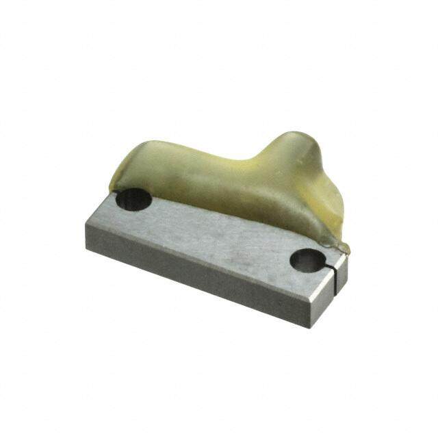
| 描述 | ADAPTER CRIMP FOR BAT-PWR TOOL |
| 产品分类 | |
| 品牌 | Molex Inc |
| 数据手册 | |
| 产品图片 |
|
| 产品型号 | 0638160600 |
| rohs | 无铅 / 符合限制有害物质指令(RoHS)规范要求 |
| 产品系列 | - |
| 其它名称 | 063816-0600 |
| 标准包装 | 1 |
| 特色产品 | http://www.digikey.cn/product-highlights/cn/zh/molex-application-tooling/4157 |
| 配件类型 | 压接适配器 |
| 配套使用产品/相关产品 | 0638160200 和 0638160250 |
| 配用 | /product-detail/zh/0638238370/WM5252-ND/2713240/product-detail/zh/0638160250/WM4481-ND/2504745/product-detail/zh/0638160200/WM4480-ND/2504744 |


- 商务部:美国ITC正式对集成电路等产品启动337调查
- 曝三星4nm工艺存在良率问题 高通将骁龙8 Gen1或转产台积电
- 太阳诱电将投资9.5亿元在常州建新厂生产MLCC 预计2023年完工
- 英特尔发布欧洲新工厂建设计划 深化IDM 2.0 战略
- 台积电先进制程称霸业界 有大客户加持明年业绩稳了
- 达到5530亿美元!SIA预计今年全球半导体销售额将创下新高
- 英特尔拟将自动驾驶子公司Mobileye上市 估值或超500亿美元
- 三星加码芯片和SET,合并消费电子和移动部门,撤换高东真等 CEO
- 三星电子宣布重大人事变动 还合并消费电子和移动部门
- 海关总署:前11个月进口集成电路产品价值2.52万亿元 增长14.8%


PDF Datasheet 数据手册内容提取
Battery Powered Crimping Tool BATTERY POWERED CRIMPING TOOL Operation Manual Order No. 63816-0200 (110 V) Order No. 63816-0250 (220 V) Order No: TM-638160200 Release Date: 12.06-07 UNCONTROLLED COPY Page 1 of 36 Revision: F Revision Date: 04-18-14
Battery Powered Crimping Tool Table of Contents BATTERY POWERED CRIMPING TOOL ........................................................................................................................ 1 Safety Warnings and Information ..................................................................................................................................... 3 SECTION 1 ...................................................................................................................................................................... 7 Description ................................................................................................................................................................................... 7 1.1. Features ....................................................................................................................................................................... 7 1.2. Technical Specifications .............................................................................................................................................. 8 1.3 Delivery Check ............................................................................................................................................................. 8 SECTION 2 ...................................................................................................................................................................... 9 Power Crimp Heads and Adapters............................................................................................................................................... 9 2.1 Comparison Chart - Hand and Power Crimp Tools.................................................................................................... 10 2.2 63816-0600 Power Crimp Adapter for Type 4A Hand Crimp Tools ........................................................................... 11 2.3 63816-0300 Power Crimp Head for Type 2C and 4C Hand Crimp Tools .................................................................. 13 2.4 63816-0800 Power Crimp Head for Type 4D Hand Crimp Tools ............................................................................... 15 2.5 63816-1600 Power Crimp Head for Type 4E Hand Crimp Tools ............................................................................... 18 2.6 63816-0900 Power Adapter for Type AT Air Crimp Heads ........................................................................................ 21 SECTION 3 .................................................................................................................................................................... 23 Set-Up and Adjustments ............................................................................................................................................................ 23 3.1 Set-Up ........................................................................................................................................................................ 24 3.2 Operation ................................................................................................................................................................... 25 3.3 Preventive Instructions .............................................................................................................................................. 26 SECTION 4 .................................................................................................................................................................... 27 General Terminal Specifications and Crimping Operation ......................................................................................................... 27 4.1 Scope ......................................................................................................................................................................... 28 4.2 Crimping Terminals .................................................................................................................................................... 28 SECTION 5 .................................................................................................................................................................... 29 Preventive Maintenance ............................................................................................................................................................ 29 5.1 Periodic Cleaning ....................................................................................................................................................... 30 5.2 Battery and Charging Unit.......................................................................................................................................... 31 5.3 Disposal ..................................................................................................................................................................... 32 5.4 Warranty .................................................................................................................................................................... 32 SECTION 6 .................................................................................................................................................................... 33 6.1 Parts List and Assembly Drawings ............................................................................................................................ 34 6.2 Troubleshooting ........................................................................................................................................................ 36 Order No: TM-638160200 Release Date: 12.06-07 UNCONTROLLED COPY Page 2 of 36 Revision: F Revision Date: 04-18-14
Battery Powered Crimping Tool Safety Warnings and Information Read and understand all of the instructions and safety information in this manual before operating or servicing this tool. Keep this manual available when using this tool. Replacement manuals are available for download at no charge at www.molex.com. SAFETY ALERT SYMBOL This symbol is used to call your attention to hazards or unsafe practices which could result in an injury or property damage. The signal word, defined below, indicates the severity of the hazard. The message after the signal word provides information for preventing or avoiding the hazard. DANGER: Indicates an imminently hazardous situation which, if not avoided, could result in death or serious injury. DANGER WARNING: Indicates a potentially hazardous situation which, if not avoided, could result in death or serious injury. WARNING CAUTION: Indicates a potentially hazardous situation which, if not avoided, may result in minor or moderate injury. CAUTION may also be used to alert against unsafe practices associated with events that could lead CAUTION to personal injury. WARNING WARNING Always wear proper eye protection when Operating or servicing this tool. Always wear proper ear protection when Failure to wear eye protection could result in Operating or servicing this tool. serious eye injury from flying debris or hydraulic oil. WARNING WARNING Electric shock hazard: Never wear clothing or jewelery that is loose or That could potentially get caught in this tool. This tool is not insulated. When using this unit near energized electrical lines, use proper personal Failure to observe this warning could result in protective equipment. Severe Injury or death. Failure to observe this warning could result in severe injury or death WARNING WARNING Pinch points: Never operate, service, install, or adjust this tool without proper instruction and without Keep hands away from the crimping head when first reading and understanding the instructions crimping. in this manual and all applicable manuals. Failure to observe this warning could result In severe injury or death. Order No: TM-638160200 Release Date: 12.06-07 UNCONTROLLED COPY Page 3 of 36 Revision: F Revision Date: 04-18-14
Battery Powered Crimping Tool WARNING WARNING Do not use compressed air to clean this tool. Do not use solvents or flammable liquids The forces created by compressed air can to clean the crimping tool. force debris into the tool. Solvents or flammable liquids could ignite and Failure to observe these precautions may cause serious injury or property damage. result in injury or property damage. WARNING WARNING Inspect tool and dies before use. Replace any Do not dispose of the battery in a fire. It will worn or damaged parts. A damaged or vent fumes and may explode. improperly assembled tool can break and strike someone nearby. Failure to observe this warning could result in severe injury from harmful fumes or burns from Failure to observe this warning could result in flying debris severe injury or death. CAUTION (cid:1) Do not operate the tool without the dies. Damage to the ram or crimping head can result. (cid:1) Do not operate with the crimping head open. Damage to the ram or seals can result. (cid:1) This tool is not designed for continuous use. After 100 crimping cycles, allow the crimping tool to cool down for 15 minutes. (cid:1) Do not place the tool in a vise. The crimping tool is designed for hand-held operation only. (cid:1) This tool may be used in damp or wet environments; however, we recommend air-drying the tool before use if it becomes soaked. (cid:1) Use this tool for the manufacturer’s intended purpose only. (cid:1) Failure to observe these precautions may result in injury or property damage CAUTION (cid:1) Do not allow anything to contact the battery’s terminals. (cid:1) Do not immerse the battery in liquid. Liquid may create a short circuit and damage the battery. (cid:1) If the battery is immersed, contact your service center for proper handling. (cid:1) Do not place the battery into a pocket, tool pouch, or tool box with conductive objects. (cid:1) Conductive objects may create a short circuit and damage the battery. (cid:1) Do not place a battery on moist ground or grass. Moisture may create a short circuit and damage the battery. Failure to observe these precautions may result in injury or property damage. CAUTION (cid:1) Do not store the battery at more than 60 °C (140 °F). Damage to the battery can result. (cid:1) Do not use another manufacturer’s charger. Other manufacturers’ chargers may overcharge and damage the battery. (cid:1) Do not attempt to open the battery. It contains no user-serviceable parts. (cid:1) Failure to observe these precautions may result in injury or property damage. CAUTION Never perform any service or maintenance other than as described in this manual. Never modify, alter or misuse the equipment Molex crimp specifications are valid only when used with Molex terminals, applicators and tooling. Failure to observe this precaution may result in injury and property damage. Order No: TM-638160200 Release Date: 12.06-07 UNCONTROLLED COPY Page 4 of 36 Revision: F Revision Date: 04-18-14
Battery Powered Crimping Tool Tooling Technical Assistance Molex offers tooling technical assistance for customers who may need some guidance for tooling adjustments. This support can be obtained by calling either of the two numbers listed below and asking for the Molex Tooling Group. Call Toll Free 1-800-786-6539 (US) 1-630-969-4550 (Global). This assistance is limited to the operation and set-up of a customer’s Molex tool. Questions with regard to Molex connector products or how to identify the proper tooling and/ or tooling documentation should be directed to your local Molex personnel or Customer Service Representative. When calling for service on this tool, a copy of the Tooling Manual and Specific Application Tooling Specification (ATS) Sheet should be present and a person that is familiar with this tool should be present. Be sure the following information is supplied: 1. Customer name 2. Customer address 3. Person to contact such as (name, title, e-mail, and telephone number 4. Power tool order number (Lease number also if applicable) 5. Serial number (Lease number also if applicable) 6. Molex Connector product order number 7. Urgency of request 8. Nature of problem Molex Application Tooling Group 2200 Wellington Court Lisle, IL 60532, USA Tel: +1 (630) 969-4550 Fax:+1 (630) 505-0049 Visit our Web site at http://www.molex.com Order No: TM-638160200 Release Date: 12.06-07 UNCONTROLLED COPY Page 5 of 36 Revision: F Revision Date: 04-18-14
Battery Powered Crimping Tool Table of Contents SECTIONS 1. General Description 2. Power Crimp Heads and Adapters 3. Set-up and Adjustments 4. Terminal Specifications and Crimping Operation 5. Preventive Maintenance 6. Parts List, Assembly Drawing, and Troubleshooting Order No: TM-638160200 Release Date: 12.06-07 UNCONTROLLED COPY Page 6 of 36 Revision: F Revision Date: 04-18-14
Battery Powered Crimping Tool SECTION 1 Principal Mechanical Parts of the 63816-0200 (110 V) and the 63816-0250 (220 V) Battery Powered Tool. Battery charger not shown. LOCKING PINS (2) CRIMPING HEAD ADAPTER RETRACTOR SLIDE TRIGGER UNLOCKING SWITCH RECHARGEABLE Figure 1-1 (NiCad 9.6V) BATTERY Description The Molex Battery Powered Tool is designed to crimp terminals with the use of interchangeable modular crimp heads or power crimp heads, and tool kits. This tool has an automatic retractable system which returns the crimping adapter along with the crimping dies to the starting position when the maximum force is reached. It is equipped with a special brake that will stop the forward motion of the crimping dies when the trigger is released. The crimping head can be rotated 360° for better access in difficult working situations. 1.1. Features (cid:1) Crimps a wide range of products with interchangeable modular crimp heads or power crimp heads, and tool kits, which reduce the overall cost and provide production flexibility. (cid:1) Modular crimp heads or power crimp head and dies are easily and quickly interchanged to reduce production down time. (cid:1) Complete portable system that allows tool to be moved and stored easily. Order No: TM-638160200 Release Date: 12.06-07 UNCONTROLLED COPY Page 7 of 36 Revision: F Revision Date: 04-18-14
Battery Powered Crimping Tool 1.2. Technical Specifications Dimensions (with battery) Length 292.1mm (11.50”) Width 76.2mm (3.00“) Depth 50.8mm (2.00“) Unpacked Weight 1.50kg (3.31lbs) Production Rate 250 cycles per hour maximum, depending on operator skill and tool kit installed. Battery Voltage 9.6V Capacity 1.3 Ah Charging Time Approximately 40 minutes, about 15 minutes with fast-charger Crimps/battery-charge 150 at 10mm2 Operating Parameters Maximum Force 15kN (1.7 tonne-force) Cycle Time 2.0 seconds Stroke Length 9.00mm (.354”) Ambient Temperature -20oC to +40oC Sound Level 75dB (A) in a distance of 1.0m Vibrations <2.5m/s2 1.3 Delivery Check Carefully remove the Battery Powered Tool from its shipping container and determine that the following items are included in the package. For the 63816-0200 (110 V): (cid:2) 63816-0200 Battery Crimping Tool (cid:2) 63816-0202 Battery Unit (2) (cid:2) 63816-0210 Battery Charger (cid:2) Carrying Case (cid:2) TM-638160200 Operation Manual For the 63816-0250 (220 V): (cid:2) 63816-0250 Battery Crimping Tool (cid:2) 63816-0202 Battery Unit (2) (cid:2) 63816-0260 Battery Charger (cid:2) Carrying Case (cid:2) TM-638160200 Operation Manual Order No: TM-638160200 Release Date: 12.06-07 UNCONTROLLED COPY Page 8 of 36 Revision: F Revision Date: 04-18-14
Battery Powered Crimping Tool SECTION 2 Power Crimp Heads and Adapters 2.1 Comparison Chart - Hand and Power Tools 2.2 63816-0600 Power Crimp Adapter for Type 4A Hand Crimp Tools 2.3 63816-0300 Power Crimp Head for Type 2C and 4C Hand Crimp Tools 2.4 63816-0800 Power Crimp Head for Type 4D Hand Crimp Tools 2.5 63816-1600 Power Crimp Head for Type 4E Hand Crimp Tools 2.6 63816-0900 Adapter for Type AT Air Crimp Tools (with 64005-0000 Head for Type RHT Hand Crimp Tools) NOTE: Hand Crimp tool “Type” with a pictorial illustration, is displayed on the upper right corner of the Hand Crimp Tool Specification Sheet (ATS) and in the following pages of this manual. Order No: TM-638160200 Release Date: 12.06-07 UNCONTROLLED COPY Page 9 of 36 Revision: F Revision Date: 04-18-14
Battery Powered Crimping Tool Comparison Chart Battery Power and Crimp Hand Tools 2.1 Comparison Chart - Hand and Power Crimp Tools SCOPE Modular crimp heads, power crimp head, adapters, and dies are easily and quickly interchanged between the hand crimp tools and the battery powered tools. See chart below. Battery Power Crimp Tool and Adapters for Hand Crimp Tools Type RHT Type 4A Type 2C Type 4C Type 4D Type 4E Type AT • See Note 64005-xx00 63816-0600 63816-0300 63816-0300 63816-0800 63816-1600 63816-0900 + 63816-0900 AT Head Adapter Head Head Head Head Adapter + Adapter 63816-0200 Battery Powered Crimp Tool • NOTE: Un-tooled AT heads are not available separately. Customers can install RHT Tooling into one of their existing AT heads. Caution must be taken as the markings on the AT head will not match the tooling from an RHT tool for a different terminal. Order No: TM-638160200 Release Date: 12.06-07 UNCONTROLLED COPY Page 10 of 36 Revision: F Revision Date: 04-18-14
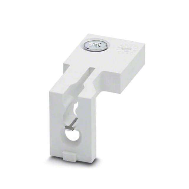
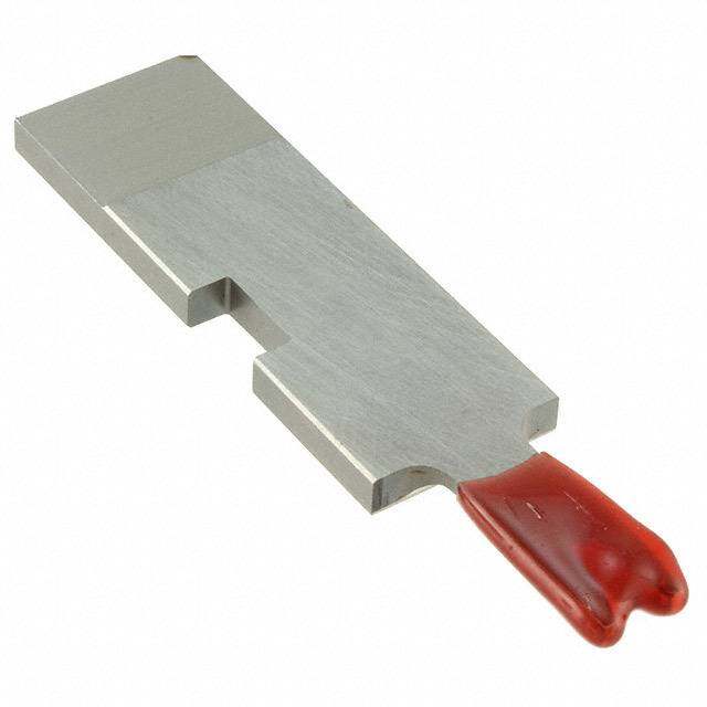
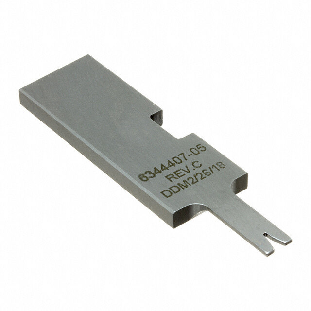
Battery Powered Crimping Tool 63816-0600 Power Crimp Adapter Application Tooling TYPE 4A For Type 4A Hand Crimp Tools 2.2 63816-0600 Power Crimp Adapter for Type 4A Hand Crimp Tools Scope The 63816-0600 Power Crimp Adapter was created for use with the Type 4A Modular Crimp Heads when used with the Battery Powered Tool (Order No. 63816-0200). Installation of Type 4A Modular Crimp Heads onto the Power Crimp Adapter To mount the Type 4A Modular Crimp Heads to the 63816-0600 Modular Crimp Adapter, slide the locking pins outward until they stop. Then place the crimp head in the upper slot and align the holes with the pins. Then, push in the pins until they lock. See Figure 2-1. TYPE 4A MODULAR CRIMP HEAD WITH TOOLING 63816-0001 LOCKING PINS (2) 63816-0600 ADAPTER Figure 2-1 Installation of Type 4A Power Crimp Adapter to Battery Powered Crimping Tool To install the 63816-0600 Power Crimp Adapter onto the 63816-0200 Battery Powered Tool, refer to Section 3, “Set-Up and Adjustments”. Operation 1. Load the terminal as described in the Operation section of the specification sheet for the tool. 2. Cycle the Battery Powered Tool to crimp the terminal to the wire. Hold the trigger until the tool completes the cycle. 3. Remove the crimped terminal from the terminal locator by pressing down on the wire stop and gently pulling on the wire. The terminal locator can be in either position. 4. Visually inspect the crimped terminal for proper crimp location. WARNING: Never place fingers into the tooling nest. Maintenance It is recommended that each operator of the tool be made aware of, and responsible for, the following maintenance steps: Order No: TM-638160200 Release Date: 12.06-07 UNCONTROLLED COPY Page 11 of 36 Revision: F Revision Date: 04-18-14
Battery Powered Crimping Tool 1. This tool was engineered for durability, but like any fine piece of equipment, it needs cleaning and lubrication for a maximum service life of trouble-free crimping 2. Remove dust, moisture and other contaminants with a clean brush, or soft, lint- free cloth. 3. Do not use any abrasive materials that could damage the tool. 4. Make certain all pins, pivot points and bearing surfaces in the tool head are protected with a thin coat of high quality machine oil. Do not oil excessively. LUBRICATION Use light oil, such as SAE 30 weight automotive oil, every 5,000 crimps or POINTS monthly, will significantly enhance the tool life and ensure a stable calibration. (BOTH SIDES) See Figure 2-2 for lubrication points. LIGHT OIL 5. Store the tool in a clean and dry area when not in use. (EVERY MONTH OR Warranty 5,000 CRIMPS) Figure 2-2 This tool is for electrical terminal crimping purposes only. This tool is made of the best quality materials. All vital components are long life-tested. All tools are warranted free of manufacturing defects for a period of 30 days. Should such a defect occur, we will repair or exchange the tool if it cannot be repaired, free of charge. This repair or exchange will not be applicable to altered, misused, or damaged tools. Parts List Item Order No. Description Quantity 1 63816-0600 Power Crimp Adapter 1 1 Figure 2-3 Order No: TM-638160200 Release Date: 12.06-07 UNCONTROLLED COPY Page 12 of 36 Revision: F Revision Date: 04-18-14
Battery Powered Crimping Tool 63816-0300 Power Crimp Head Application Tooling Type 2C Type 4C Hand Crimp Tools 2.3 63816-0300 Power Crimp Head for Type 2C and 4C Hand Crimp Tools SCOPE The 63816-0300 Power Crimp Head was created for use with the Type 2C and 4C Crimp Dies and Locator Kits when used with the Battery Powered Tool (Order No. 63816-0200). Installation of Type 2C or 4C Crimp Tool Kit into the Power Crimp Head 1. Remove the Crimp Tool Kit from the Type 2C or 4C Hand Crimp Tool. To do this, see the instruction sheet included with the hand crimp tool. 2. To install the Crimp Tool Kit into the Power Crimp Head, follow the steps below: POWER CRIMP HEAD PUNCHES M4 X 18 LONG BHCS M4 X 10 LONG BHCS ANVILS Figure 2-4 1. Insert the Anvils into the bottom slots of the nest. The wire size markings face toward the front of the head, opposite from the locator pivot shaft. Install the M4 x 10 long BHCS and tighten in place. 2. Insert the Punches into the top slots of the nest with wire size markings to the front. Install the M4 x 18 long BHCS and tighten in place. See Figure 2-4. 3. Position the locator with the hole over the brass pivot shaft and snap it into place. See Figure 2-5. WARNING: Never place fingers into the tooling nest. Power Crimp Head Installation onto Battery Powered Crimping Tool To install the 63816-0300 Power Crimp Head onto the 63816-0200 Battery Powered Crimping Tool, refer to Section 3, “Set- Up and Adjustments”. Order No: TM-638160200 Release Date: 12.06-07 UNCONTROLLED COPY Page 13 of 36 Revision: F Revision Date: 04-18-14
Battery Powered Crimping Tool Operation 1. Load the terminal as described in the Operation section of the specification sheet for the tool. 2. Cycle the Battery Powered Tool to crimp the terminal to the wire. Hold the trigger until the tool completes the cycle. 3. Remove the crimped terminal from the terminal locator by pressing down on the wire stop and gently pulling on the wire. The terminal locator can be in either position. 4. Visually inspect the crimped terminal for proper crimp location. Maintenance It is recommended that each operator of the tool be made aware of, and responsible for, the following maintenance steps: 1. Remove dust, moisture and other contaminants with a clean brush, or soft, lint-free LUBRICATION cloth. POINTS 2. Do not use any abrasive materials that could damage the tool. (BOTH SIDES) 3. Make certain all pins, pivot points and bearing surfaces in the tool head are LIGHT OIL protected with a thin coat of high quality machine oil. Do not oil excessively. This (EVERY MONTH tool was engineered for durability, but like any fine piece of equipment, it needs OR cleaning and lubrication for a maximum service life of trouble-free crimping. Use 5,000 CRIMPS) light oil, such as SAE 30 weight automotive oil, every 5,000 crimps or monthly, will significantly enhance the tool life and ensure a stable calibration. See Figure 2-6 for Figure 2-6 lubrication points. 4. Store the tool in a clean and dry area when not in use. Warranty This tool is for electrical terminal crimping purposes only. This tool is made of the best quality materials. All vital components are long life-tested. All tools are warranted free of manufacturing defects for a period of 30 days. Should such a defect occur, we will repair or exchange the tool if it cannot be repaired, free of charge. This repair or exchange will not be applicable to altered, misused, or damaged tools. Parts List Item Order No Description Quantity 1 63816-0300 Power Crimp Head 1 2 63811-4773 Universal Locator Mount 1 M4 X 8 LONG BHCS (REF) 2 Figure 2-7 1 Order No: TM-638160200 Release Date: 12.06-07 UNCONTROLLED COPY Page 14 of 36 Revision: F Revision Date: 04-18-14
Battery Powered Crimping Tool 63816-0800 Power Crimp Head TYPE 4D Application Tooling Type 4D Hand Crimp Tools 2.4 63816-0800 Power Crimp Head for Type 4D Hand Crimp Tools SCOPE The 63816-0800 Power Crimp Head was created for use with Type 4D Crimp Dies and Locator when used with the Battery Powered Tool (Order No. 63816-0200). Installation for Type 4D Crimp Tooling Installation into Power Crimp Head First, remove the locator and the crimp tooling from the Type 4D Hand Crimp Tool. To do this, see the instruction below. To remove the locator from the Type 4D Crimp Hand Tool 1. Open the crimp hand tool by squeezing the handles together to remove LOCATOR the locator. 2. Squeeze gently on the lower area of the locator assembly, shown in Figure SQUEEZE 2-8 with your thumb and index finger. The lower tabs of the locator should HERE disengage from the Power Crimp Head. 3. Lift and pull away from the crimp hand tool. The top locator hooks should slip out of the top slots easily. See Figure 2-8. SQUEEZE HERE Figure 2-8 TOP SLOTS OF HANDTOOL JAWS TOOLING OPEN TOP HOOKS TOOLING M3 BHCS LOWER TABS Figure 2-9 HANDLE OPEN Removing the Crimp Dies from the Type 4D Crimp Hand Tool 1. Open the crimp hand tool by squeezing the handles together. 2. Remove the two M3 BHCS. 3. Remove the crimp dies as shown in Figure 2-9. 4. Make sure all of components removed from the crimp hand tool are reinstalled into the Power Crimp Head in the same manner. Note: The tool part number markings on the dies go inward so they will not be visible when installed. See Figure 2-11. Installing the Crimp Dies in the Power Crimp Head 1. Select the desired Type 4D crimping dies. 2. Insert the Anvils or dies (E1 and I1) into the bottom slots of the nest. Install the M3 x 14 long BHCS and lightly tighten in place. See Figure 2-10. Order No: TM-638160200 Release Date: 12.06-07 UNCONTROLLED COPY Page 15 of 36 Revision: F Revision Date: 04-18-14
Battery Powered Crimping Tool E2 POWER CRIMP HEAD MATCH UP MARKINGS I2 M3 BHCS E1 X 8 LONG Figure 2-11 WIRE GAUGE Figure 2-10 I1 IDENTIFICATIONS FRONT BACK M3 BHCS X 14 LONG SHOWING To install the locator in the Power Crimp Head 1. Install the locator assembly. 2. Press the red insert down as far as it will go. See Figure 2-12. 3. The locator goes on the opposite side from the dies with the wire gauge markings. 4. While holding onto the lower part of the locator with your thumb and index finger, insert the locator top hooks (2) into the Power Crimp Head top slots. 5. Rotate the locator down and press the lower tabs into the two bottom slots of the head. To secure the locator into place, the lower tabs must snap into place on the head frame. MAKE SURE CENTER OF LOCATOR IS IN THE DOWN POSITION TOP SLOT OF TOP SLOT THE HANDTOOL OF THE LOCATOR SQUEEZE TOP HOOKS HANDTOOL HERE SQUEEZE Figure 2-13 HERE Figure 2-12 LOWER TABS Note: Make sure the longer screw only goes into the lower dies. 6. Completely close the crimp dies until they are touching, and then securely KNURLED KNOB tighten the M3 BHCS. Power Crimp Head Installation onto Battery Powered Crimping Tool LOCKING To install the 63813-0800 Power Crimp Head onto the 63816-0200 Battery SET SCREW Powered Tool, refer to Section 3, “Set-Up and Adjustments”. Adjustments The crimp height on the 63816-0800 Power Crimp Head can be adjusted, if necessary. To do this, first measure the conductor crimp height of a crimped terminal and compare to the crimp specification listed in the product specification Figure 2-14 for that terminal. If an adjustment is required, follow the procedure, below: 1. Loosen the locking set screw located just below the knurled knob at the top of the Power Crimp Head. See Figure 2-14. 2. If the crimp height is too loose, rotate the knob, a small amount, in the counter-clockwise direction. Crimp another terminal and re-check the crimp height. Order No: TM-638160200 Release Date: 12.06-07 UNCONTROLLED COPY Page 16 of 36 Revision: F Revision Date: 04-18-14
Battery Powered Crimping Tool 3. If the crimp height is too tight, turn the knob clockwise and follow the same procedure. 4. Do this until the proper crimp height is achieved. 5. When the proper crimp height is achieved, lock the set screw. Operation LUBRICATION 1. To load a terminal and position the wire in the terminal in the Power Crimp POINTS Head, follow the loading procedure as explained in the Hand Crimp Tool (BOTH SIDES) Specification sheet. LIGHT OIL 2. Crimp the terminal by squeezing the trigger on the side of the battery actuator (EVERY MONTH until the tool cycles and returns and the jaws open. OR 3. Remove the terminal from the locator and inspect the crimp for proper quality. 5,000 CRIMPS) WARNING: Never place fingers into the tooling nest. Figure 2-15 Maintenance It is recommended that each operator of the tool be made aware of, and responsible for, the following maintenance steps: This tool was engineered for durability, but like any fine piece of equipment, it needs cleaning and lubrication for a maximum service life of trouble-free crimping Remove dust, moisture and other contaminants with a clean brush, or soft, lint-free cloth. Do not use any abrasive materials that could damage the tool. Use light oil, such as SAE 30 weight automotive oil, every 5,000 crimps, or monthly, will significantly enhance the tool life and ensure a stable calibration. Make certain all sliding surfaces in the tool head are protected with a thin coat of high quality machine oil. See Figure 2-15 for lubrication points. Do not oil excessively and wipe excess oil from the tool frame when complete. Store the tool in a clean and dry area when not in use. Warranty This tool is for electrical terminal crimping purposes only. This tool is made of the best quality materials. All vital components are long life-tested. All tools are warranted free of manufacturing defects for a period of 30 days. Should such a defect occur, we will repair or exchange the tool if it cannot be repaired, free of charge. This repair or exchange will not be applicable to altered, misused, or damaged tools. Parts List Item Order No Description Quantity 1 63816-0800 Power Crimp Head (for style 4D crimp tools) 1 2 63816-0801 Return Spring 2 2 2 Figure 2-16 1 Order No: TM-638160200 Release Date: 12.06-07 UNCONTROLLED COPY Page 17 of 36 Revision: F Revision Date: 04-18-14
Battery Powered Crimping Tool 63816-1600 Power Crimp Head Type 4E Application Tooling Type 4E Hand Crimp Tools 2.5 63816-1600 Power Crimp Head for Type 4E Hand Crimp Tools SCOPE The 63816-1600 Power Crimp Head was created for use with Type 4E Crimp Dies and Locator when used with the Battery Powered Tool (Order No. 63816-0200). Installation for Type 4E Crimp Tooling Installation into Power Crimp Head First, remove the locator and the crimp tooling from the Type 4E Hand Crimp Tool. To do this, see the instruction below. Remove the locator from the Type 4E Crimp Hand Tool 1. Remove the M4 lock nut from the locator. 2. Loosen the (2) pegs on the locator assembly from the mating holes on the back side of the Power Crimp Head and pull out. See Figure 2-17. M4 x 30 LONG LOCATOR JAWS SHCS OPEN TOOLING M4 BHCS Figure 2-18 Figure 2-17 M4 LOCK NUT Removing the Crimp Dies from the Type 4E Crimp Hand Tool 1. Open the crimp hand tool. 2. Remove the two M4 BHCS. 3. Remove the crimp dies as shown in Figure 2-18. PUNCHES 4. Make sure all of components removed from the Crimp Hand Tool are reinstalled into the Power Crimp Head in the same manner. M4 X 12 LONG Installing the Crimp Dies in the Power Crimp Head BHCS 1. Select the desired Type 4E crimping dies. 2. Insert the Anvils or dies into the bottom slots of the nest. Install the M4 x 30 long BHCS and lightly tighten in place. See Figure 2-19. ANVILS 3. Make sure the small markings on the individual dies match up and the wire gauge identification (AWG) marks should be aligned and facing out on the side of the crimp head with the two button head screws on the ram. M4 X 30 LONG Figure 2-19 BHCS Order No: TM-638160200 Release Date: 12.06-07 UNCONTROLLED COPY Page 18 of 36 Revision: F Revision Date: 04-18-14
Battery Powered Crimping Tool 4. Install the M4 x 30 long BHCS and lightly tighten in place. Note: Make sure the longer screw only goes into the lower dies. M4 x 30 LONG SHCS 5. Install the Insert the Punches or dies (E2 and I2) into the top slot of the crimp head frame. 6. Install the M4 x 12 long BHCS and lightly tighten in place. 7. Completely close the crimp dies until they are touching, and then secure both M4 BHCS (TORX drive). To install the locator in the Power Crimp Head LOCATOR 1. Locate the (2) pegs on the locator assembly into the mating holes on the back M4 LOCK NUT Figure 2-20 side of the Power Crimp Head. 2. Install and tighten the M4 lock nut. See Figure 2-20. 3. Completely close the crimp dies until they are touching, and then securely tighten the M4 BHCS. Operation 1. To load a terminal in the Power Crimp Head and position the wire in the terminal, follow the loading procedure as explained in the Hand Crimp Tool or Bench Top Crimp Machine Specification sheet. 2. Crimp the terminal by actuating the crimp tool until it cycles and returns and the jaws open. 3. Remove the terminal from the locator and inspect the crimp for proper quality. CAUTION: Never place fingers into the tooling nest area. Maintenance It is recommended that each operator of the tool be made aware of, and responsible for, the following maintenance steps: 1. This tool was engineered for durability, but like any fine piece of equipment, it needs cleaning and lubrication for a maximum service life of trouble-free crimping. LUBRICATION 2. Remove dust, moisture and other contaminants with a clean brush, or soft, lint- POINTS free cloth. (BOTH SIDES) 3. Do not use any abrasive materials that could damage the tool. LIGHT OIL 4. The use of a light oil, such as SAE 30 weight automotive oil, every 5,000 (EVERY MONTH OR crimps, or monthly, will significantly enhance the tool life and ensure a stable 5,000 CRIMPS) calibration. Make certain all sliding surfaces in the tool head are protected with a thin coat of high quality machine oil. See Figure 2-21 for lubrication points. Do not oil excessively and wipe excess oil from the tool frame when complete. 5. Store the tool in a clean and dry area when not in use. Figure 2-21 Warranty This tool is for electrical terminal crimping purposes only. This tool is made of the best quality materials. All vital components are long life-tested. All tools are warranted free of manufacturing defects for a period of 30 days. Should such a defect occur, we will repair or exchange the tool free of charge. This repair or exchange will not be applicable to altered, misused, or damaged tools. Order No: TM-638160200 Release Date: 12.06-07 UNCONTROLLED COPY Page 19 of 36 Revision: F Revision Date: 04-18-14
Battery Powered Crimping Tool Parts List Item Order No Description Quantity 1 63816-1600 Power Crimp Head (for style 4E crimp tools) 1 2 63816-1601 Return Spring 2 1 2 2 RETURN RETURN SPRING SPRING Figure 2-22 Order No: TM-638160200 Release Date: 12.06-07 UNCONTROLLED COPY Page 20 of 36 Revision: F Revision Date: 04-18-14
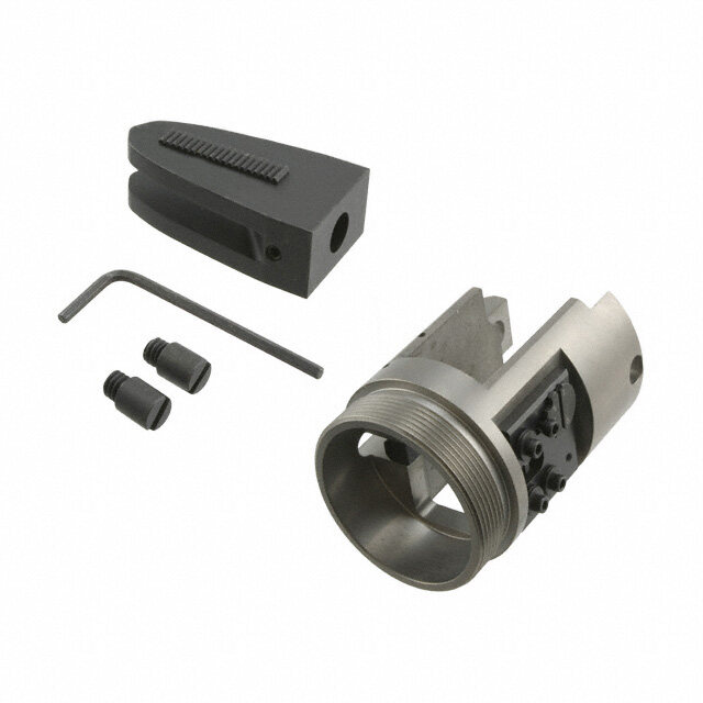
Battery Powered Crimping Tool 63816-0900 Power Adapter Application Tooling Type RHT Type AT Hand Crimp Tools and Air Crimp Heads 2.6 63816-0900 Power Adapter for Type AT Air Crimp Heads (With 64005-0000 Head for Type RHT Hand Crimp Tools) SCOPE The 63816-0900 Power Adapter was created to adapt the 64005 and 64007 series Type AT Crimp Heads for use in the 63816-0200 Battery Powered Tool. The addition, customers who have Type RHT hand crimp tools along with a Type AT Crimp Head, can load the RHT dies and locator into the AT crimp head and then in the Battery Powered Tool Installation Type AT Air Crimp Head Installation into AT Power Adapter Install the AT Air Crimp Head onto the AT Power Adapter as shown in Figure 2-23. Type RHT Crimp Tool Kit into AT Head and AT Power Adapter (One AT Crimp Head required) Remove the Crimp Tooling Kit from the Type RHT Hand Crimp Tool. To do this, see the instruction sheet included with the hand crimp tool. 1. Install the RHT tooling kit with locator, into the AT Power Crimp Head. See Figures 2-24. 2. Then install the crimp head onto the AT Power Adapter. This is a typical Type RHT Crimp Tooling Kit arrangement in AT Head. See Figure 2-15. AT CRIMP HEAD AT CRIMP HEAD ADAPTER AT HEAD Figure 2-23 RHT CRIMP SLOTTED SCREW (2) TOOLING KIT Figure 2-24 For specific tooling, see the specification sheet that is included with the RHT tool. WARNING: Never place fingers into the tooling nest. Order No: TM-638160200 Release Date: 12.06-07 UNCONTROLLED COPY Page 21 of 36 Revision: F Revision Date: 04-18-14
Battery Powered Crimping Tool Installation of Power Crimp Head with Power Adapter to the Battery Powered Crimping Tool To install the 63816-0900 Power Adapter onto the 63816-0200 Battery Powered Tool, refer to Section 4, “Set-Up and Adjustments”. Operation 1. To load a terminal and position the wire in the terminal in the Power Crimp Head, LUBRICATION POINTS follow the loading procedure as explained in the AT Crimp Head (or RHT Hand Crimp (BOTH SIDES) Tool) instruction sheet. LIGHT OIL 2. Crimp the terminal by squeezing the trigger on the side of the battery actuator until (EVERY MONTH the tool cycles and returns and the jaws open. OR 3. Remove the terminal from the locator and inspect the crimp for proper quality. 5,000 CRIMPS) Maintenance It is recommended that each operator of the tool be made aware of, and responsible for, the following maintenance steps: 6. This tool was engineered for durability, but like any fine piece of equipment, it needs cleaning and lubrication for a maximum service life of trouble-free crimping 7. Remove dust, moisture and other contaminants with a clean brush, or soft, lint-free Figure 2-25 cloth. 8. Do not use any abrasive materials that could damage the tool. 9. Make certain all pins, pivot points and bearing surfaces in the tool head are protected with a thin coat of high quality machine oil. Do not oil excessively. Use light oil, such as SAE 30 weight automotive oil, every 5,000 crimps or monthly, will significantly enhance the tool life and ensure a stable calibration. See Figure 2-25 for lubrication points. 10. Store the tool in a clean and dry area when not in use. Warranty This tool is for electrical terminal crimping purposes only. This tool is made of the best quality materials. All vital components are long life-tested. All tools are warranted free of manufacturing defects for a period of 30 days. Should such a defect occur, we will repair or exchange the tool if it cannot be repaired, free of charge. This repair or exchange will not be applicable to altered, misused, or damaged tools. Parts List Item Order No. Description Quantity 1 63816-0900 Power Crimp Adapter 1 2 19279-0161 Slotted Screw 2 1 2 Figure 2-26 Order No: TM-638160200 Release Date: 12.06-07 UNCONTROLLED COPY Page 22 of 36 Revision: F Revision Date: 04-18-14
Battery Powered Crimping Tool SECTION 3 Set-Up and Adjustments 3.1. Set-up 3.2. Operation 3.3. Preventive Instructions Order No: TM-638160200 Release Date: 12.06-07 UNCONTROLLED COPY Page 23 of 36 Revision: F Revision Date: 04-18-14
Battery Powered Crimping Tool 3.1 Set-Up Figure 3-1 Replacing Power or Modular Crimp Heads 63806-0900 (Type AT) 63816-0600 (Type 4A) TYPE AT MODULAR MODULAR TYPE 4A CRIMP CRIMP HEAD HEAD WITH TOOLING LOCKING PINS (2) SLOTTED 63816-0600 SCREWS (2) ADAPTER 63816-0900 ADAPTER LOCKING PINS (2) YOKE LOCKING YOKE PINS (2) BATTERY POWERED BATTERY TOOL POWERED TOOL RETRACT RETRACT SLIDE SLIDE 63816-0300 (Type 2C OR 4C) 63816-0800 (Type 4D) 63816-1600 (Type 4E) TYPE 4E POWER TYPE 2C or CRIMP TYPE4C POWER CRIMP HEAD TYPE 4D HEAD NO TOOLING POWER SHOWN LOCKING CRIMP LATCH HEAD YOKE CRIMP HEAD YOKE YOKE ADAPTER CRIMP HEAD CRIMP HEAD LOCKING LOCKING ADAPTER LOCKING ADAPTER PINS (2) PINS (2) BATTERY PINS (2) BATTERY POWERED BATTERY POWERED TOOL POWERED TOOL TOOL RETRACT RETRACT RETRACT SLIDE SLIDE SLIDE Before starting any work on electrical applications, make sure there are no live cables or parts in the immediate area of the user. Warning: Remove the battery from the crimping tool before installing and removing dies in the crimp head. 1. Select the appropriate modular crimp head or power crimp head with the proper tooling kit inserted for the application needed. The Modular Crimp Head with the Battery Powered Crimp Adapter or the Power Crimp Head are sold separately. Order No: TM-638160200 Release Date: 12.06-07 UNCONTROLLED COPY Page 24 of 36 Revision: F Revision Date: 04-18-14
Battery Powered Crimping Tool 2. Remove the locking pins (2) from the battery powered crimp yoke. 3. Place the modular crimp head into the yoke and push down until it engages into the slot of the adapter. The Power Crimp Heads do not require a separate Power Crimp Adapter. 4. Replace the locking pins (2) making sure the modular crimp head or the Power Crimp Head are secure. The locking pins can be inserted from either side of the yoke. See Figure 3-1. WARNING: Electric shock hazard: This tool is not insulated. When using this unit near energized electrical lines, use proper personal protective equipment. Failure to observe this warning could result in severe injury or death WARNING: Wear eye protection when operating or servicing this tool. Failure to wear eye protection could result in serious eye injury from flying debris or hydraulic oil. 3.2 Operation WITH LOCATOR TYPE 2C AND 4C TERMINAL POWER CRIMP HEAD TYPE 4A AND WIRE WITH LOCATOR MODULAR CRIMP HEAD IN PLACE WITH LOCATOR TERMINAL AND WIRE IN PLACE TYPE 4A POWER CRIMP ADAPTER HOLD TRIGGER HOLD TRIGGER DOWN DOWN Figure 3-2 1. Insert the proper terminal or connector into the tooling nest and push on the trigger in the handle just enough so the dies contact the terminal or connector securely. Release the trigger. This allows the operator to make adjustments to the connector before the final termination. See Figure 3-2. 2. Insert the wire or cable into the terminal. Push on the wire or cable to assure it is fully seated in the terminal. 3. Hold the trigger down again until the crimping tool achieves pressure relief, which is accompanied by an audible “pop”. The crimping operation can be interrupted at any time during the cycle by releasing the trigger. 4. The crimping cycle is complete when the dies are completely closed and the maximum crimping force is reached. The dies will automatically release and will go back to their original position. Note: In case of an error or emergency, the ram can be retracted before the crimping cycle is complete. To do this push the retractor slide towards the battery. See Figure 3-1. Warning: An incomplete crimp can cause a fire. (cid:1) Use proper die, connector, and cable combinations. Improper combinations can result in an incomplete crimp. (cid:1) The relief valve will sound to indicate a completed crimp. If you do not hear the sound of the relief valve, the crimp is not complete. Failure to observe these warnings could result in severe injury or death. Order No: TM-638160200 Release Date: 12.06-07 UNCONTROLLED COPY Page 25 of 36 Revision: F Revision Date: 04-18-14
Battery Powered Crimping Tool 3.3 Preventive Instructions WARNING: Do not dispose of the battery in a fire. It will vent fumes and may explode. Failure to observe this warning could result in severe injury from harmful fumes or burns from flying debris WARNING: Inspect tool and dies before use. Replace any worn or damaged parts. A damaged or improperly assembled tool can break and strike someone nearby. Failure to observe this warning could result in severe injury or death. CAUTION: (cid:1) Do not operate the tool without the dies. Damage to the ram or crimping head can result. (cid:1) Do not operate with the crimping head open. Damage to the ram or seals can result. (cid:1) This tool is not designed for continuous use. After 100 crimping cycles, allow the crimping tool to cool down for 15 minutes. (cid:1) Do not place the tool in a vise. The crimping tool is designed for hand-held operation only. (cid:1) This tool may be used in damp or wet environments; however, we recommend air-drying the tool before use if it becomes soaked. (cid:1) Use this tool for the manufacturer’s intended purpose only. Failure to observe these precautions may result in injury or property damage. CAUTION: (cid:1) Do not allow anything to contact the battery’s terminals. (cid:1) Do not immerse the battery in liquid. Liquid may create a short circuit and damage the battery. (cid:1) If the battery is immersed, contact your service center for proper handling. (cid:1) Do not place the battery into a pocket, tool pouch, or tool box with conductive objects. (cid:1) Conductive objects may create a short circuit and damage the battery. (cid:1) Do not place a battery on moist ground or grass. Moisture may create a short circuit and damage the battery. Failure to observe these precautions may result in injury or property damage. Avoid dropping this tool. Extreme shock may damage the internal mechanism and result in malfunction of the tool. Order No: TM-638160200 Release Date: 12.06-07 UNCONTROLLED COPY Page 26 of 36 Revision: F Revision Date: 04-18-14
Battery Powered Crimping Tool SECTION 4 General Terminal Specifications and Crimping Operation 4.1. Scope 4.2. Crimping Terminals Order No: TM-638160200 Release Date: 12.06-07 UNCONTROLLED COPY Page 27 of 36 Revision: F Revision Date: 04-18-14
Battery Powered Crimping Tool 4.1 Scope This tool is designed to crimp various Molex terminals and splices using our offering of crimping heads. Testing Mechanical The tensile test, or pull test, is a means of evaluating the mechanical properties of the crimped connections. The following charts show the UL specifications for various wire sizes. The tensile strength is shown in pound-force, which indicates the minimum acceptable force to break or separate the terminal from the conductor. Wire Size (AWG) Tooling Color Code *UL – 486A **UL – 486C ***MIL-T-7928 22 8 8 20 13 10 18 20 10 16 30 15 14 50 25 12 70 35 10 80 40 8 Red 90 45 225 6 Blue 100 50 300 4 Yellow 140 - 400 2 Red 180 - 550 1 Blue 200 - 650 1/0 Blue 250 - 700 2/0 Yellow 300 - 750 3/0 Red 350 - 825 4/0 Blue 450 - 875 *UL – 486A – Terminals (Copper Conductors Only) **UL – 486C – Butt Slices and Parallel Slices (Over 6 AWG use 486A values) ***MIL-T-7928 - Military Approved Terminals only as listed 4.2 Crimping Terminals Specifications and Instructions for crimping are included with the individual Hand Tool / Modular Crimp Heads. These documents are called the Application Tooling Specification (ATS) Sheets. These come with complete Hand Tools / Module Crimp Heads. If another copy is needed search on the www.Molex.com for the hand tool order number desired. In the section Specification & Other Documents click on the Application Tooling Specification (PDF) (ATS-EN). Order No: TM-638160200 Release Date: 12.06-07 UNCONTROLLED COPY Page 28 of 36 Revision: F Revision Date: 04-18-14
Battery Powered Crimping Tool SECTION 5 Preventive Maintenance 5.1. Periodic Cleaning 5.2. Storage 5.3. Battery and Charging Unit 5.4. Disposal 5.5. Warranty Order No: TM-638160200 Release Date: 12.06-07 UNCONTROLLED COPY Page 29 of 36 Revision: F Revision Date: 04-18-14
Battery Powered Crimping Tool 5.1 Periodic Cleaning Always clean tool after use and keep moving parts clear of dirt and debris. This tool is basically maintenance free, only the bolt joints at the crimping head have to be oiled regularly. Before use: Inspect dies for wear or damage such as cracks, gouges, or chips. Inspect the tool for damage or leaks. If damage is detected, return the tool to a Molex representative for inspection. After use: Wipe all tool surfaces clean with a damp cloth and mild detergent. Excessive dirt and grit can contribute to the premature wear of the tool’s internal mechanical parts. If this tool becomes dirty with excessive debris it may jam and become damaged during operation. Fully retract the ram. Place the tool in the carrying case. Store in a cool, dry place. Charge the battery. WARNING: Do not use compressed air to clean this tool. The forces created by compressed air can force debris into the tool. Failure to observe these precautions may result in injury or property damage. WARNING: Do not use solvents or flammable liquids to clean the crimping tool. Solvents or flammable liquids could ignite and cause serious injury or property damage. Monthly: Thoroughly clean all surfaces. A routine should be established to keep the tool as free from dirt as possible. An example of a maintenance chart is shown below. Copy and use this chart to track the maintenance of this crimping tool or use this as a template to create your own schedule or use your company’s standard chart, if applicable. Preventive Maintenance Chart CHECK SHEET MONTH YEAR _________ Daily Days of the Week Week Solution Use MON TUE WED THU FRI SAT SUN 1 2 3 4 Cleaning Daily After use Lubrication (2) bolts in crimping head Use SAE 10W Hydraulic oil Schedule should be adjusted up or down depending on usage. Molex recommends that a log of preventive maintenance be kept with the tool. Order No: TM-638160200 Release Date: 12.06-07 UNCONTROLLED COPY Page 30 of 36 Revision: F Revision Date: 04-18-14
Battery Powered Crimping Tool 5.2 Battery and Charging Unit WARNING: Do not dispose of the battery in a fire. It will vent fumes and may explode. Failure to observe this warning could result in severe injury from harmful fumes or burns from flying debris CAUTION: (cid:1) Do not store the battery at more than 60 °C (140 °F). Damage to the battery can result. (cid:1) Do not use another manufacturer’s charger. Other manufacturers’ chargers may overcharge and damage the battery. (cid:1) Do not attempt to open the battery. It contains no user-serviceable parts. Failure to observe these precautions may result in injury or property damage. CAUTION: (cid:1) Do not allow anything to contact the battery’s terminals. (cid:1) Do not immerse the battery in liquid. Liquid may create a short circuit and damage the battery. (cid:1) If the battery is immersed, contact your service center for proper handling. (cid:1) Do not place the battery into a pocket, tool pouch, or tool box with conductive objects. (cid:1) Conductive objects may create a short circuit and damage the battery. (cid:1) Do not place a battery on moist ground or grass. Moisture may create a short circuit and damage the battery. Failure to observe these precautions may result in injury or property damage. The charging unit is run with a nominal voltage of 110V or 220V (for Europe) and a frequency of 50-60Hz . New batteries must be charged before use. To remove the battery from the crimping tool push down on the battery lock and pull out. See Figure 5-1. To charge the battery plug in the charging unit into a power source and slide the battery upside down into the charging unit. The normal charging time is about 40 minutes. The charging level of the battery cartridge can be checked by the right LED (multicolor) of the charging unit. Color Left LED (red) Right LED (multicolor) Red Charging Unit is ready to operate. Battery defect Charging Battery is out of order. Red Battery too hot or too cold. Remove the battery. New or unused battery’s Flashing Safety components possibly defected. voltage capacity is insufficient. Green --- Charging cycle stared. Battery fully charged. Charging unit switches automatically Green --- into a maintaining level. Flashing Battery can stay in charge for an indefinite time without being damaged. Yellow --- Battery is at least 90% charged. Charging can be terminated. If the Right LED does not light up, the circuit of the battery --- Unit not powered is disconnected or the battery is incorrectly polarized. Notes: If the standard capacity of the battery is not achieved, it does not mean that the battery is faulty. The full capacity of the battery can be achieved after 3 charging/discharging cycles. 1. If there is a noticeable decrease in speed of the crimping tool the battery should be recharged. Charge the battery at room temperature between 10°C-40°C (50°F-104°F). 2. The battery should be charged before storing. Order No: TM-638160200 Release Date: 12.06-07 UNCONTROLLED COPY Page 31 of 36 Revision: F Revision Date: 04-18-14
Battery Powered Crimping Tool Cautions: 1. Charging a battery which has been used recently or in the sun or a long period of time the right LED might flash red (battery temperature) greater than 65°C (149°F). In this case let the battery cool down and try again. 2. Charging the battery at low temperatures under 5°C (41°F) is not possible. The battery temperature must be warmed up before starting the battery cycle again. 3. Do not expose the charging unit to rain or snow. 4. Do not charge the battery in or around explosive materials or gases. 5. Do not use any other (dry or car) battery with the charging unit or the crimping tool. 6. Do not use the cord as a handle to carry the battery unit. 7. Do not pull the cord out of a wall socket with force. 8. Do not pull the plug of the charging unit until after the battery has been charged. 9. Do not insert foreign objects into the ducts of the charging unit. 10. Do not disassemble the charging unit. 11. Do not place the battery in your pocket or a tool box, if there are conductive materials such as coins, keys, tools or other metallic parts, they may cause injury or property damage. 5.3 Disposal PUSH DOWN ON BATTERY When this tool is no longer operating properly the different components of this tool will need LOCK to be disposed of separately. 1. The battery must be disposed of according to the Rechargeable Battery Recycling BATTERY Corporation (RBRC) in the USA, or other applicable guidelines in other countries. UNIT 2. The remaining parts of this tool must be disposed of according to the domestic environmental standards or the Environmental Protection Agency (EPA) in the USA, or other applicable guidelines in other countries. 3. Because of possible environmental damage, we recommend disposal of the tool by a Figure 5-1 professional company. Do not dispose of this tool in your residential or commercial waste, as it would be hazardous to the environment. 5.4 Warranty All tools are warranted to be free of manufacturing defects for a period of 30 days. Should such a defect occur, we will repair or exchange the tool free of charge. This repair or exchange will not be applicable to altered, misused, or damaged tools. This tool is designed for hand use only. Any clamping, fixturing, or use of handle extensions voids this warranty. After one year Molex recommends the crimping tool be returned to a Molex representative for inspection. Only the heads of the crimping tool are permitted to be changed by the operator. Do not damage the seals of this tool. If seals are damaged the warranty is void. CAUTION: Molex crimp specifications are valid only when used with Molex terminals and tooling. Order No: TM-638160200 Release Date: 12.06-07 UNCONTROLLED COPY Page 32 of 36 Revision: F Revision Date: 04-18-14
Battery Powered Crimping Tool SECTION 6 6.1. Parts List and Assembly Drawing 6.2. Troubleshooting Order No: TM-638160200 Release Date: 12.06-07 UNCONTROLLED COPY Page 33 of 36 Revision: F Revision Date: 04-18-14
Battery Powered Crimping Tool 6.1 Parts List and Assembly Drawings Item Order No Description Quantity 1 63816-0200 or 63816-0250 Battery Powered Tool (110 V) or Battery Powered Tool (220 V) 1 2 63816-0001 Modular Crimp Head Locking Pins 2 3 63816-0202 Battery Unit 2 4 63816-0210 or 63816-0260 Battery Charger (110 V) or (220 V) Not Shown 1 2 1 Figure 6-1 Item No. 4 Not Shown 3 Note: The following Modular Crimp Heads and Battery Powered Crimp Adapters are sold separately and are not included with the 63816-0200 (110 V) or the 63816-0250 (220 V) Battery Powered Tool. The chart below shows all applications for the Battery Powered Tool. See Figure 6-2 and 6-3. Applications for the Battery Powered Tool Crimp Head Order No. Adapter Order No. Adapter Description Tool Order no. Tool Description (Sold separately) (Sold separately) (Sold separately) 638xx-xx70 63816-0200 (110 V) 63816-0600 (Type 4A) Battery Power Figure 6-2 Modular or Battery Power Tool 6400x-xx00 Crimp Adapter 63816-0250 (220 V) 63816-0900 (AT) 63816-0300 (Type 2C or 4C) 63816-0200 (110 V) 63816-0800 Figure 6-3 Power or Battery Power Tool N/A N/A (Type 4D) 63816-0250 (220 V) 63816-1600 (Type 4E) Order No: TM-638160200 Release Date: 12.06-07 UNCONTROLLED COPY Page 34 of 36 Revision: F Revision Date: 04-18-14
Battery Powered Crimping Tool Figure 6-2 Modular Crimp Head TYPE AT MODULAR TYPE 4A CRIMP HEAD MODULAR WITH TOOLING LOCKING CRIMP HEAD PINS (2) WITH TOOLING SLOTTED SCREWS (2) 63816-0600 63816-0900 ADAPTER ADAPTER LOCKING PINS (2) LOCKING PINS (2) BATTERY BATTERY POWERED TOOL POWERED TOOL TYPE 4A TYPE AT Figure 6-3 Power Crimp Head TYPE 4E TYPE 4D POWER CRIMP POWER CRIMP HEAD HEAD (NO TOOLING SHOWN) TYPE 2C OR TYPE 4C POWER CRIMP HEAD LOCKING LOCKING LOCKING PINS (2) PINS (2) PINS (2) BATTERY BATTERY POWERED POWERED TOOL BATTERY TOOL POWERED TOOL TYPE 2C or TYPE 4C TYPE 4D TYPE 4E Order No: TM-638160200 Release Date: 12.06-07 UNCONTROLLED COPY Page 35 of 36 Revision: F Revision Date: 04-18-14
Battery Powered Crimping Tool 6.2 Troubleshooting Make sure the battery is charged before toubleshooting this tool. Symptom Cause Solution (cid:1) Dirt, contaminants, etc., Clean the tool. in ram area of tool. Tool is inoperative. (cid:1) Battery unit contacts corroded. Clean contacts with pencil eraser or contact cleaner (cid:1) Battery unit contacts damaged. Reform the contacts. (cid:1) Tool parts worn or damaged. Contact a Molex representative. Dies stop (cid:1) Battery charge is low. Charge or replace battery unit. during operation. LED glows for (cid:1) Battery charge is low. Charge or replace battery unit. 20 seconds. Visit our Web site at http://www.molex.com Order No: TM-638160200 Release Date: 12.06-07 UNCONTROLLED COPY Page 36 of 36 Revision: F Revision Date: 04-18-14