ICGOO在线商城 > FKP3J012203D00KSSD
 Datasheet下载
- 型号: FKP3J012203D00KSSD
- 制造商: WIMA
- 库位|库存: xxxx|xxxx
- 要求:
| 数量阶梯 | 香港交货 | 国内含税 |
| +xxxx | $xxxx | ¥xxxx |
查看当月历史价格
查看今年历史价格
FKP3J012203D00KSSD产品简介:
ICGOO电子元器件商城为您提供FKP3J012203D00KSSD由WIMA设计生产,在icgoo商城现货销售,并且可以通过原厂、代理商等渠道进行代购。 提供FKP3J012203D00KSSD价格参考以及WIMAFKP3J012203D00KSSD封装/规格参数等产品信息。 你可以下载FKP3J012203D00KSSD参考资料、Datasheet数据手册功能说明书, 资料中有FKP3J012203D00KSSD详细功能的应用电路图电压和使用方法及教程。
| 参数 | 数值 |
| 品牌 | WIMA |
| 产品目录 | 无源元件 |
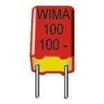
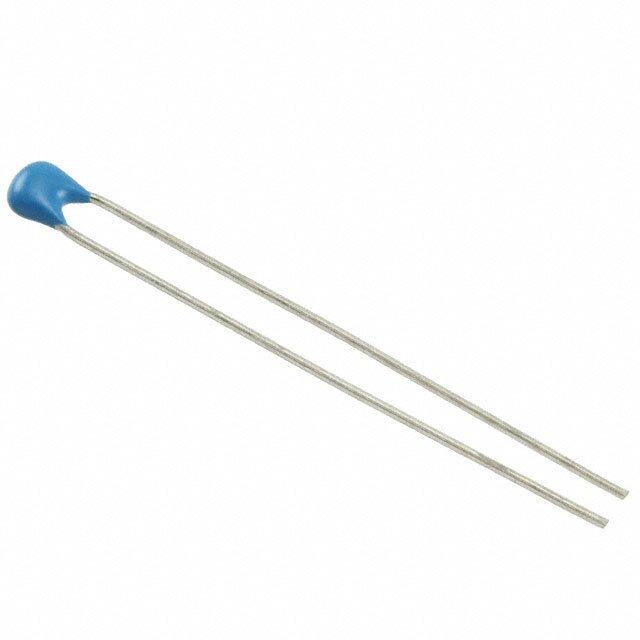
| 描述 | 薄膜电容器 2200pF 630V 10% PCM10 |
| 产品分类 | |
| 产品手册 | |
| 产品图片 |
|
| rohs | 符合RoHS |
| 产品系列 | 薄膜电容器,WIMA FKP3J012203D00KSSD |
| 产品型号 | FKP3J012203D00KSSD |
| 产品 | AC and Pulse Film Capacitors |
| 产品种类 | |
| 商标 | WIMA |
| 外壳宽度 | 4 mm |
| 外壳长度 | 13. mm |
| 外壳高度 | 9.5 mm |
| 容差 | 10 % |
| 引线间隔 | 10 mm |
| 最大工作温度 | + 100 C |
| 最小工作温度 | - 55 C |
| 电介质 | Polypropylene (PP) |
| 电压额定值AC | 300 V |
| 电压额定值DC | 630 V |
| 电容 | 2200 pF |
| 端接类型 | Radial |
| 类型 | Polypropylenen Film and Foil Capacitors |
| 系列 | FKP3 |
| 零件号别名 | FKP3-2200/630/10P10 |


- 商务部:美国ITC正式对集成电路等产品启动337调查
- 曝三星4nm工艺存在良率问题 高通将骁龙8 Gen1或转产台积电
- 太阳诱电将投资9.5亿元在常州建新厂生产MLCC 预计2023年完工
- 英特尔发布欧洲新工厂建设计划 深化IDM 2.0 战略
- 台积电先进制程称霸业界 有大客户加持明年业绩稳了
- 达到5530亿美元!SIA预计今年全球半导体销售额将创下新高
- 英特尔拟将自动驾驶子公司Mobileye上市 估值或超500亿美元
- 三星加码芯片和SET,合并消费电子和移动部门,撤换高东真等 CEO
- 三星电子宣布重大人事变动 还合并消费电子和移动部门
- 海关总署:前11个月进口集成电路产品价值2.52万亿元 增长14.8%


PDF Datasheet 数据手册内容提取
D WIMA FKP 3 Polypropylene (PP) Film and Foil Capacitors for Pulse Applications in PCM 7.5 mm to 15 mm. Capacitances from 100 pF to 0.22 mF. Rated Voltages from 63 VDC to 1000 VDC. Special Features Electrical Data ˜ Pulse duty construction Capacitance range: Dielectric absorption: ˜ Very low dissipation factor 100 pF to 0.22 mF (E12-values on request) 0.05 % ˜ Negative capacitance change Rated voltages: Temperature coefficient: versus temperature 63 VDC, 100 VDC, 250 VDC, 400 VDC, –200 x 10-6/+ C (general guide) ˜ Very low dielectric absorption 630 VDC, 850 VDC, 1000 VDC Dissipation factors at +20+ C: tan d ˜ According to RoHS 2011/65/EU Capacitance tolerances: at f C0.1 mF 0.1 mF P C 0.22 mF ±20%, ±10%, ±5% Typical Applications Operating temperature range: 1 kHz 5 x 10⁻⁴ 5 x 10⁻⁴ –55+ C to +100+ C 10 kHz 6 x 10⁻⁴ 6 x 10⁻⁴ For high frequency applications e.g. Test specifications: 100 kHz 8 x 10⁻⁴ – ˜ Sample and hold In accordance with IEC 60384-13 Voltage derating: ˜ Timing Climatic test category: A voltage derating factor of 1.35 % per K ˜ LC-Filtering 55/100/56 in accordance with IEC must be applied from +85+ C for DC ˜ Oscillating circuits Insulation resistance at +20+ C: voltages and from +75+ C for AC ˜ Audio equipment 3 x 10⁵ M¸ voltages. Measuring voltage: Reliability: Construction Ur = 63 V: Utest = 50 V/1 min. Operational life 300 000 hours Ur 100 V: Utest = 100 V/1 min. Failure rateP 5 fit (0.5 x Ur and 40+ C) Test voltage: 2 U, 2 sec. Dielectric: r Maximum pulse rise time: Polypropylene (PP) film 1000 V/msec for pulses equal to the Capacitor electrodes: rated voltage Metal foil Internal construction: Plasticfilm Mechanical Tests Packing Metalfoilelectrode Terminatingwire Pull test on pins: Available taped and reeled. 10 N in direction of pins according to IEC 60068-2-21 Detailed taping information and graphs Vibration: at the end of the catalogue. 6 hours at 10 ... 2000 Hz and 0.75 mm Encapsulation: displacement amplitude or 10 g in Solvent-resistant, flame-retardant plastic accordance with IEC 60068-2-6 case with epoxy resin seal, UL 94 V-0 Low air density: Terminations: 1kPa = 10 mbar in accordance with Tinned wire. IEC 60068-2-13 Marking: Bump test: Colour: Red. Marking: Black. 4000 bumps at 390 m/sec2 in For further details and graphs please accordance with IEC 60068-2-29 refer to Technical Information. 6 1 7. 0 40
D WIMA FKP 3 Continuation General Data 63 VDC/40 VAC* 100 VDC/63 VAC* Capacitance W H L PCM** Part number W H L PCM** Part number 100 pF 3 8.5 10 7.5 FKP3D001002B00_ _ _ _ 150 „ 3 8.5 10 7.5 FKP3D001502B00_ _ _ _ 220 „ 3 8.5 10 7.5 FKP3D002202B00_ _ _ _ 330 „ 3 8.5 10 7.5 FKP3D003302B00_ _ _ _ 470 „ 3 8.5 10 7.5 FKP3D004702B00_ _ _ _ 680 „ 3 8.5 10 7.5 FKP3D006802B00_ _ _ _ 1000 pF 3 8.5 10 7.5 FKP3D011002B00_ _ _ _ 1500 „ 3 8.5 10 7.5 FKP3D011502B00_ _ _ _ 2200 „ 3 8.5 10 7.5 FKP3D012202B00_ _ _ _ 3300 „ 3 8.5 10 7.5 FKP3D013302B00_ _ _ _ 4700 „ 3 8.5 10 7.5 FKP3D014702B00_ _ _ _ 6800 „ 4 9 10 7.5 FKP3D016802C00_ _ _ _ 0.01 mF 4 9 10 7.5 FKP3D021002C00_ _ _ _ 0.015 „ 4 9 10 7.5 FKP3C021502C00_ _ _ _ 4 9.5 13 10 FKP3D021503D00_ _ _ _ 0.022 „ 4 9.5 13 10 FKP3C022203D00_ _ _ _ 5 11 13 10 FKP3D022203F00_ _ _ _ 0.033 „ 4 9.5 13 10 FKP3C023303D00_ _ _ _ 6 12 13 10 FKP3D023303G00_ _ _ _ 0.047 „ 5 11 13 10 FKP3C024703F00_ _ _ _ 5 11 18 15 FKP3D024704B00_ _ _ _ 0.068 „ 6 12 13 10 FKP3C026803G00_ _ _ _ 6 12.5 18 15 FKP3D026804C00_ _ _ _ 0.1 mF 6 12.5 18 15 FKP3C031004C00_ _ _ _ 7 14 18 15 FKP3D031004D00_ _ _ _ 0.15 „ 8 15 18 15 FKP3C031504F00_ _ _ _ 9 16 18 15 FKP3D031504J00_ _ _ _ 0.22 „ 9 16 18 15 FKP3C032204J00_ _ _ _ 250 VDC/160 VAC* 400 VDC/250 VAC* Capacitance W H L PCM** Part number W H L PCM** Part number 100 pF 3 8.5 10 7.5 FKP3F001002B00_ _ _ _ 3 8.5 10 7.5 FKP3G001002B00_ _ _ _ 150 „ 3 8.5 10 7.5 FKP3F001502B00_ _ _ _ 3 8.5 10 7.5 FKP3G001502B00_ _ _ _ 220 „ 3 8.5 10 7.5 FKP3F002202B00_ _ _ _ 3 8.5 10 7.5 FKP3G002202B00_ _ _ _ 330 „ 3 8.5 10 7.5 FKP3F003302B00_ _ _ _ 3 8.5 10 7.5 FKP3G003302B00_ _ _ _ 470 „ 3 8.5 10 7.5 FKP3F004702B00_ _ _ _ 3 8.5 10 7.5 FKP3G004702B00_ _ _ _ 680 „ 3 8.5 10 7.5 FKP3F006802B00_ _ _ _ 3 8.5 10 7.5 FKP3G006802B00_ _ _ _ 1000 pF 3 8.5 10 7.5 FKP3F011002B00_ _ _ _ 3 8.5 10 7.5 FKP3G011002B00_ _ _ _ 1500 „ 3 8.5 10 7.5 FKP3F011502B00_ _ _ _ 4 9 10 7.5 FKP3G011502C00_ _ _ _ 2200 „ 4 9 10 7.5 FKP3F012202C00_ _ _ _ 4 9 10 7.5 FKP3G012202C00_ _ _ _ 4 9.5 13 10 FKP3G012203D00_ _ _ _ 3300 „ 3 9 13 10 FKP3F013303A00_ _ _ _ 4 9.5 13 10 FKP3G013303D00_ _ _ _ 4700 „ 4 9.5 13 10 FKP3F014703D00_ _ _ _ 5 11 13 10 FKP3G014703F00_ _ _ _ 6800 „ 5 11 13 10 FKP3F016803F00_ _ _ _ 6 12 13 10 FKP3G016803G00_ _ _ _ 0.01 mF 5 11 13 10 FKP3F021003F00_ _ _ _ 5 11 18 15 FKP3G021004B00_ _ _ _ 0.015 „ 6 12 13 10 FKP3F021503G00_ _ _ _ 6 12.5 18 15 FKP3G021504C00_ _ _ _ 5 11 18 15 FKP3F021504B00_ _ _ _ 0.022 „ 6 12.5 18 15 FKP3F022204C00_ _ _ _ 7 14 18 15 FKP3G022204D00_ _ _ _ 0.033 „ 7 14 18 15 FKP3F023304D00_ _ _ _ 8 15 18 15 FKP3G023304F00_ _ _ _ 0.047 „ 8 15 18 15 FKP3F024704F00_ _ _ _ 9 16 18 15 FKP3G024704J00_ _ _ _ 0.068 „ 9 16 18 15 FKP3F026804J00_ _ _ _ * AC voltage: f 1000 Hz; 1.4 x Urms + UDC Ur W L Part number completion: ** PCM = Printed circuit module = pin spacing Tolerance: 20 % = M H Dims. in mm. 10 % = K d = 0.5 P if W = 3 5 % = J PCM 7.5 and 10 d = 0.6 P if W 4 6-2 Packing: bulk = S d d = 0.8 P if PCM = 15 PCM Pin length: 6-2 = SD atthepinexitpoints 8 (±0.4) Taped version see page 148. 1 Rights reserved to amend design data without prior notification. 4. 0 Continuation page 42 41
D WIMA FKP 3 Continuation General Data 630 VDC/300 VAC* 850 VDC/300 VAC* Capacitance W H L PCM** Part number W H L PCM** Part number 100 pF 3 8.5 10 7.5 FKP3J001002B00_ _ _ _ 3 8.5 10 7.5 FKP3M001002B00_ _ _ _ 150 „ 3 8.5 10 7.5 FKP3J001502B00_ _ _ _ 3 8.5 10 7.5 FKP3M001502B00_ _ _ _ 220 „ 3 8.5 10 7.5 FKP3J002202B00_ _ _ _ 3 8.5 10 7.5 FKP3M002202B00_ _ _ _ 330 „ 3 8.5 10 7.5 FKP3J003302B00_ _ _ _ 3 8.5 10 7.5 FKP3M003302B00_ _ _ _ 470 „ 3 8.5 10 7.5 FKP3J004702B00_ _ _ _ 3 8.5 10 7.5 FKP3M004702B00_ _ _ _ 680 „ 3 8.5 10 7.5 FKP3J006802B00_ _ _ _ 3 8.5 10 7.5 FKP3M006802B00_ _ _ _ 1000 pF 4 9 10 7.5 FKP3J011002C00_ _ _ _ 4 9 10 7.5 FKP3M011002C00_ _ _ _ 1500 „ 4 9.5 13 10 FKP3J011503D00_ _ _ _ 4 9.5 13 10 FKP3M011503D00_ _ _ _ 2200 „ 4 9.5 13 10 FKP3J012203D00_ _ _ _ 4 9.5 13 10 FKP3M012203D00_ _ _ _ 3300 „ 5 11 13 10 FKP3J013303F00_ _ _ _ 5 11 13 10 FKP3M013303F00_ _ _ _ 4700 „ 6 12 13 10 FKP3J014703G00_ _ _ _ 6 12 13 10 FKP3M014703G00_ _ _ _ 6800 „ 5 11 18 15 FKP3J016804B00_ _ _ _ 5 11 18 15 FKP3M016804B00_ _ _ _ 0.01 mF 6 12.5 18 15 FKP3J021004C00_ _ _ _ 6 12.5 18 15 FKP3M021004C00_ _ _ _ 0.015 „ 8 15 18 15 FKP3J021504F00_ _ _ _ 8 15 18 15 FKP3M021504F00_ _ _ _ 0.022 „ 9 16 18 15 FKP3J022204J00_ _ _ _ 9 16 18 15 FKP3M022204J00_ _ _ _ 0.033 „ 9 16 18 15 FKP3J023304J00_ _ _ _ 1000 VDC300 VAC* * AC voltage: f 1000 Hz; 1.4 x Urms + UDC Ur Capacitance W H L PCM** Part number New range 100 pF 3 8.5 10 7.5 FKP3O101002B00_ _ _ _ ** PCM = Printed circuit module = pin spacing 150 „ 3 8.5 10 7.5 FKP3O101502B00_ _ _ _ 220 „ 3 8.5 10 7.5 FKP3O102202B00_ _ _ _ Dims. in mm. 330 „ 3 8.5 10 7.5 FKP3O103302B00_ _ _ _ 470 „ 3 8.5 10 7.5 FKP3O104702B00_ _ _ _ Part number completion: 680 „ 3 8.5 10 7.5 FKP3O106802B00_ _ _ _ Tolerance: 20 % = M 1000 pF 4 9 10 7.5 FKP3O111002C00_ _ _ _ 10 % = K 1500 „ 4 9.5 13 10 FKP3O111503D00_ _ _ _ 5 % = J 2200 „ 4 9.5 13 10 FKP3O112203D00_ _ _ _ Packing: bulk = S 3300 „ 5 11 13 10 FKP3O113303F00_ _ _ _ Pin length: 6-2 = SD 4700 „ 6 12 13 10 FKP3O114703G00_ _ _ _ 6800 „ 5 11 18 15 FKP3O116804B00_ _ _ _ Taped version see page 148. 0.01 mF 6 12.5 18 15 FKP3O121004C00_ _ _ _ 0.015 „ 8 15 18 15 FKP3O121504F00_ _ _ _ 0.022 „ 9 16 18 15 FKP3O122204J00_ _ _ _ Rights reserved to amend design data without prior notification. Urms Permissible AC voltage V5 in relation to frequency 100VDC at 10) C internal temperature rise 2 (general guide). 102 63 52 0.1µF0.01.502µ2F0µ.0F47µF04.70010µpFF1000p2F2002p2F0p4F17000ppFF 101 104 2 5 105 2 5 106 2 5 f107 Hz 8 1 4. 0 42
D Recommendation for Processing and Application of Through-Hole Capacitors Soldering Process Internal temperature of the capacitor must be kept as follows: Polyester: preheating: Tmax. 125° C soldering: Tmax. 135° C Polypropylene: preheating: Tmax. 100° C soldering: Tmax. 110° C Single wave soldering Soldering bath temperature: T P 260 ° C Dwell time: t P 5 sec Double wave soldering Soldering bath temperature: T P 260 ° C Dwell time: St P 5 sec Due to different soldering processes and heat requirements the graphs are to be regarded as a recommendation only. WIMA Quality and Environmental Philosophy ISO 9001:2008 Certification WIMA Environmental Policy RoHS Compliance ISO 9001:2008 is an international basic All WIMA capacitors, irrespective of According to the RoHS Directive 2011/65/EU standard of quality assurance systems whether through-hole devices or SMD, certain hazardous substances like e.g. lead, for all branches of industry. The approval are made of environmentally friendly cadmium, mercury must not be used any according to ISO 9001:2008 of our facto- materials. Neither during manufacture longer in electronic equipment as of July 1st, ries by the infaz (Institut für Auditierung und nor in the product itself any toxic sub- 2006. For the sake of the environment WIMA Zertifizierung) certifies that organisation, stances are used, e.g. has refraind from using such substances since equipment and monitoring of quality assu- years already. – Lead – PBB/PBDE rance in our factories correspond to inter- – PCB – Arsenic nationally recognized standards. – CFC – Cadmium – Hydrocarbon chloride – Mercury WIMA WPCS – Chromium 6+ – etc. WIMA Kondensatoren sind bleifrei We merely use pure, recyclable materials konform RoHS 2011/65/EU The WIMA Process Control System (WPCS) for packing our components, such as: WIMA capacitors are lead free is a quality surveillance and optimization in accordance with RoHS 2011/65/EU system developed by WIMA. WPCS is a major part of the quality-oriented WIMA ” carton production. Points of application during ” cardboard production process: ” adhesive tape made of paper Tape for lead-free WIMA capacitors ” polystyrene ” incoming material inspection ” metallization ” film inspection We almost completely refrain from using ” schoopage packing materials such as: DIN EN ISO 14001:2004 ” pre-healing ” pin attachment ” foamed polystyrene (Styropor®) WIMA’s environmental management has ” cast resin preparation/ ” adhesive tapes made of plastic been established in accordance with the encapsulation ” metal clips guidelines of DIN EN ISO 14001:2004 to ” 100% final inspection optimize the production processes with ” Testing as per customer requirements regard to energy and resources. 8 1 4. 0 15
D Typical Dimensions for Taping Configuration Vh P2 P 1 P1 W2 H H Diagram1: W0 W1 PCM2.5/5/7.5mm W D0 d F P0 t P P 1 H P1 P1 H d d F P0 P2 P0 P2 F Diagram2:PCM10/15mm Diagram3:PCM22.5and27.5*mm *PCM27.5tapingpossiblewithtwofeedholesbetweencomponents Dimensions for Radial Taping Designation Symbol PCM 2.5 taping PCM 5 taping PCM 7.5 taping PCM 10 taping* PCM 15 taping* PCM 22.5 taping PCM 27.5 taping Carrier tape width W 18.0 p0.5 18.0 p0.5 18.0 p0.5 18.0 p0.5 18.0 p0.5 18.0 p0.5 18.0 p0.5 for hot-sealing for hot-sealing for hot-sealing for hot-sealing for hot-sealing for hot-sealing for hot-sealing Hold-down tape width W 6.0 6.0 12.0 12.0 12.0 12.0 12.0 0 adhesive tape adhesive tape adhesive tape adhesive tape adhesive tape adhesive tape adhesive tape Hole position W1 9.0 p0.5 9.0 p0.5 9.0 p0.5 9.0 p0.5 9.0 p0.5 9.0 p0.5 9.0 p0.5 Hold-down tape position W 0.5 to 3.0 max. 0.5 to 3.0 max. 0.5 to 3.0 max. 0.5 to 3.0 max. 0.5 to 3.0 max. 0.5 to 3.0 max. 0.5 to 3.0 max. 2 Feed hole diameter D0 4.0 p0.2 4.0 p0.2 4.0 p0.2 4.0 p0.2 4.0 p0.2 4.0 p0.2 4.0 p0.2 Pitch of component P 12.7 p1.0 12.7 p1.0 12.7 p1.0 25.4 p1.0 25.4 p1.0 38.1 p1.5 3*8.1 p1.5 or 50.8 p1.5 cumulative pitch cumulative pitch cumulative pitch cumulative pitch cumulative pitch cumulative pitch cumulative pitch Feed hole pitch P 0 1 2 .7 p 0 . 3 1e.r0ro mr mm/a2x0. pitch 1 2 . 7 p 0 . 3 1e.r0ro mr mm/a2x0. pitch 1 2 . 7 p 0 . 3 1e.r0ro mr mm/a2x0. pitch 1 2 . 7 p 0 . 3 1e.r0ro mr mm/a2x0. pitch 1 2 . 7 p 0 . 3 1e.r0ro mr mm/a2x0. pitch 1 2 . 7 p 0 . 3 1e.r0ro mr mm/a2x0. pitch 1 2 . 7 p 0 . 3 1e.r0ro mr mm/a2x0. pitch Feed hole centre to pin P1 5.1 p0.5 3.85 p0.7 2.6 p0.7 7.7 p0.7 5.2 p0.7 7.8 p0.7 5.3 p0.7 Hole centre to component centre P2 6.35 p1.3 6.35 p1.3 6.35 p1.3 12.7 p1.3 12.7 p1.3 19.05 p1.3 19.05 p1.3 Feed hole centre to bottom 16.5 p0.3 16.5 p0.3 16.5 p0.5 16.5 p0.5 16.5 p0.5 16.5 p0.5 16.5 p0.5 H edge of the component 18.5 p0.5 18.5 p0.5 18.5 p0.5 18.5 p0.5 18.5 p0.5 18.5 p0.5 18.5 p0.5 Feed hole centre to top H+H < H H+H < H H+H < H H+H < H H+H < H H+H < H H+H < H H component 1 component 1 component 1 component 1 component 1 component 1 component 1 edge of the component 1 32.25 max. 32.25 max. 24.5 to 31.5 25.0 to 31.5 26.0 to 37.0 30.0 to 43.0 35.0 to 45.0 uPipnp sepr aecdingge aotf carrier tape F 2 .5 p0.5 5 . 0 +–00..28 7.5 p0.8 10.0 p0.8 15 p0.8 22.5 p0.8 27.5 p0.8 Pin diameter d 0.4 p0.05 0.5 p0.05 „ 0.5 p0.05 or 0.6 +–00..0065 „ 0.5 p0.05 or 0.6 +–00,.0065 0.8 +–00,.0085 0.8 +–00,.0085 0.8 +–00..0085 Component alignment Dh p 2.0 max. p 2.0 max. p 3.0 max. p 3.0 max. p 3.0 max. p 3.0 max. p 3.0 max. Total tape thickness t 0.6 p0.2 0.6 p0.2 0.6 p0.2 0.6 p0.2 0.6 p0.2 0.6 p0.2 0.6 p0.2 ROLL/AMMO AMMO Package (see also page 149) R EEL PP 3306 0p m1a x. B 5582 pp22 dcoempepn. ddiinmge onsni ons R EEL PP 33600 p m1a x. B 556826 ppp222 or REEL PP 52050 p m1a x. B 656048 ppp222 dcoonem pPepCnoMdnie nangnt dd imensions Unit see details page 150. Dims in mm. „ Diameter of pins see General Data. Please clarify customer-specific deviations with the manufacturer. * PCM 10 and PCM 15 can be crimped to PCM 7.5. 8 1 Position of components according to PCM 7.5 (sketch 1). P0 = 12.7 or 15.0 is possible 4. 0 148
D Types of Tape Packaging of Capacitors for Automatic Radial Insertion ˜ ROLL Packaging ˜ AMMO Packaging ˜ REEL Packaging ax.ax. mm 340 370 (cid:31)3205±±11 60 max.00 max. 35 ax. m 0 4 3 340 max. 50 max. 34409 0m amx.ax. 50 max. 70 max. B BAR CODE (Labelling) Labelling of package units in BARCODE „Code 39” plain text and with alphanumerical Bar Code Scanner decoding of „ WIMA supplier number „ Customer‘s P/O number „ Customer‘s part number „ WIMA confirmation number „ WIMA part number „ Lot number „ Date code „ Quantity In addition part description of – article – capacitance value – rated voltage – dimensions – capacitance tolerance – packing as well as gross weight and customer‘s name are indicated in plain text. 8 1 4. 0 149
D Packing Quantities for Capacitors with Radial Pins in PCM 2.5 mm to 22.5 mm pcs. per packing unit ROLL REEL AMMO Size PCM bulk P 360 P 500 340 x 340 490 x 370 H16.5 H18.5 H16.5 H18.5 H16.5 H18.5 H16.5 H18.5 H16.5 H18.5 W H L Codes S N O F I H J A C B D 2.5 7 4.6 0B 5000 2200 2500 – 2800 – 3 7.5 4.6 0C 5000 2000 2300 – 2300 – 2.5 mm 3.8 8.5 4.6 0D 5000 1500 1800 – 1800 – 4.6 9 4.6 0E 5000 1200 1500 – 1500 – 5.5 10 4.6 0F 5000 900 1200 – 1200 – 2.5 6.5 7.2 1A 5000 2200 2500 – 2800 – 3 7.5 7.2 1B 5000 2000 2300 – 2300 – 3.5 8.5 7.2 1C 5000 1600 2000 – 2000 – 4.5 6 7.2 1D 6000 1300 1500 – 1500 – 4.5 9.5 7.2 1E 4000 1300 1500 – 1500 – 5 10 7.2 1F 3500 1100 1400 – 1400 – 5 mm 5.5 7 7.2 1G 4000 1000 1200 – 1200 – 5.5 11.5 7.2 1H 2500 1000 1200 – 1200 – 6.5 8 7.2 1I 2500 800 1000 – 1000 – 7.2 8.5 7.2 1J 2500 700 1000 – 1000 – 7.2 13 7.2 1K 2000 700 950 – 1000 – 8.5 10 7.2 1L 2000 600 800 – 800 – 8.5 14 7.2 1M 1500 600 800 – 800 – 11 16 7.2 1N 1000 500 600 – 400 – 2.5 7 10 2A 5000 – 2500 4400 2500 – 3 8.5 10 2B 5000 – 2200 4300 2300 4150 4 9 10 2C 4000 – 1700 3200 1700 3100 7.5 mm 4.5 9.5 10.3 2D 3500 – 1500 2900 1400 2700 5 10.5 10.3 2E 3000 – 1300 2500 1300 – 5.7 12.5 10.3 2F 2000 – 1000 2200 1100 – 7.2 12.5 10.3 2G 1500 – 900 1800 1000 – 3 9 13 3A 3000 – 1100 2200 – 1900 4 8.5 13.5 FA 3000 – 900 1600 – 1450 4 9 13 3C 3000 – 900 1600 – 1450 4 9.5 13 3D 3000 – 900 1600 – 1400 10 mm 5 10 13.5 FB 2000 – 700 1300 – 1200 5 11 13 3F 3000 – 700 1300 – 1200 6 12 13 3G 2400 – 550 1100 – 1000 6 12.5 13 3H 2400 – 550 1100 – 1000 8 12 13 3I 2000 – 400 800 – 740 5 11 18 4B 2400 – 600 1200 – 1150 5 13 19 FC 1000 – 600 1200 – 1200 6 12.5 18 4C 2000 – 500 1000 – 1000 6 14 19 FD 1000 – 500 1000 – 1000 7 14 18 4D 1600 – 450 900 – 850 7 15 19 FE 1000 – 450 900 – 850 15 mm 8 15 18 4F 1200 – 400 800 – 740 8 17 19 FF 500 – 400 800 – 740 9 14 18 4H 1200 – 350 700 – 650 9 16 18 4J 900 – 350 700 – 650 10 18 19 FG 500 – 300 650 – 590 11 14 18 4M 1000 – 300 600 – 540 5 14 26.5 5A 1200 – – 800 – 770 6 15 26.5 5B 1000 – – 700 – 640 7 16.5 26.5 5D 760 – – 600 – 550 8 20 28 FH 500 – – 500 – 480 22.5 mm 8.5 18.5 26.5 5F 500 – – 480 – 450 10 22 28 FI 570* – – 420 – 380 10.5 19 26.5 5G 594* – – 400 – 360 10.5 20.5 26.5 5H 594* – – 400 – 360 11 21 26.5 5I 561* – – 380 – 350 12 24 28 FJ 480* – – 350 – 310 * TPS (Tray-Packing-System). Plate versions may have different packing units. Moulded versions. Rights reserved to amend design data without prior notification. Samples and pre-production needs on request. 8 1 4. 0 150
D Packing Quantities for Capacitors with Radial Pins in PCM 27.5 mm to 52.5 mm pcs. per packing unit ROLL REEL AMMO Size PCM bulk P 360 P 500 340 x 340 490 x 370 H16.5 H18.5 H16.5 H18.5 H16.5 H18.5 H16.5 H18.5 H16.5 H18.5 W H L Codes S N O F I H J A C B D 9 19 31.5 6A 567* – – 460/340* – 420 11 21 31.5 6B 459* – – 380/280* – 350 13 24 31.5 6D 378* – – 300 – 290 13 25 33 FK 405* – – – – – 27.5 mm 15 26 31.5 6F 324* – – 270 – 250 15 26 33 FL 324* – – – – – 17 29 31.5 6G 198* – – – – – 17 34.5 31.5 6I 198* – – – – – 20 32 33 FM 162* – – – – – 20 39.5 31.5 6J 162* – – – – – 9 19 41.5 7A 441* – – – – – 11 22 41.5 7B 357* – – – – – 13 24 41.5 7C 294* – – – – – 15 26 41.5 7D 252* – – – – – 17 29 41.5 7E 154* – – – – – 37.5 mm 19 32 41.5 7F 140* – – – – – 20 39.5 41.5 7G 126* – – – – – 24 45.5 41.5 7H 112* – – – – – 31 46 41.5 7I 84* – – – – – 35 50 41.5 7J 35* – – – – – 40 55 41.5 7K 28* – – – – – 19 31 56 8D 120* – – – – – 23 34 56 8E 80* – – – – – 48.5 mm 27 37.5 56 8H 84* – – – – – 33 48 56 8J 25* – – – – – 37 54 56 8L 25* – – – – – 25 45 57 9D 70* – – – – – 30 45 57 9E 60* 52.5 mm 35 50 57 9F 25* 45 55 57 9H 20* – – – – – 45 65 57 9J 20* – – – – – * for 2-inch transport pitches. Moulded versions. Rights reserved to amend design data without prior notification. * TPS (Tray-Packing-System). Plate versions may have different packing units. Samples and pre-production needs on request. Updated data on www.wima.com 8 1 4. 0 151
D WIMA Part Number System A WIMA part number consists of 18 digits and is composed as follows: Field 1 - 4: Type description Field 5 - 6: Rated voltage Field 7 - 10: Capacitance Field 11 - 12: Size and PCM Field 13 - 14: Version code (e.g. Snubber versions) Field 15: Capacitance tolerance Field 16: Packing Field 17 - 18: Pin length (untaped) 1 2 3 4 5 6 7 8 9 10 11 12 13 14 15 16 17 18 M K S 2 C 0 2 1 0 0 1 A 0 0 M S S D MKS 2 63 VDC 0.01 mF 2.5 x 6.5 x 7.2 - 20 % bulk 6 -2 Type description: Rated voltage: Capacitance: Size: Tolerance: SMD-PET = SMDT 50 VDC = B0 22 pF = 0022 4.8 x 3.3 x 3 Size 1812 = KA ±20 % = M SMD-PEN = SMDN 63 VDC = C0 47 pF = 0047 4.8 x 3.3 x 4 Size 1812 = KB ±10 % = K SMD-PPS = SMDI 100 VDC = D0 100 pF = 0100 5.7 x 5.1 x 3.5 Size 2220= QA ±5 % = J FKP 02 = FKP0 250 VDC = F0 150 pF = 0150 5.7 x 5.1 x 4.5 Size 2220= QB ±2.5 % = H MKS 02 = MKS0 400 VDC = G0 220 pF = 0220 7.2 x 6.1 x 3 Size 2824 = TA ±1 % = E FKS 2 = FKS2 450 VDC = H0 330 pF = 0330 7.2 x 6.1 x 5 Size 2824 = TB ... FKP 2 = FKP2 520 VDC = H2 470 pF = 0470 10.2 x 7.6 x 5 Size 4030 = VA FKS 3 = FKS3 600 VDC = I0 680 pF = 0680 12.7 x 10.2 x 6 Size 5040 = XA FKP 3 = FKP 3 630 VDC = J0 1000 pF = 1100 15.3 x 13.7 x 7 Size 6054 = YA Packing: MKS 2 = MKS2 700 VDC = K0 1500 pF = 1150 2.5 x 7 x 4.6 PCM 2.5 = 0B AMMO H16.5 340 x 340 = A MKP 2 = MKP2 800 VDC = L0 2200 pF = 1220 3 x 7.5 x 4.6 PCM 2.5 = 0C AMMO H16.5 490 x 370 = B MKS 4 = MKS4 850 VDC = M0 3300 pF = 1330 2.5 x 6.5 x 7.2 PCM 5 = 1A AMMO H18.5 340 x 340 = C MKP 4C = MKPC 900 VDC = N0 4700 pF = 1470 3 x 7.5 x 7.2 PCM 5 = 1B AMMO H18.5 490 x 370 = D MKP 4 = MKP4 1000 VDC = O1 6800 pF = 1680 2.5 x 7 x 10 PCM 7.5 = 2A REEL H16.5 360 = F MKP 10 = MKP1 1100 VDC = P0 0.01 mF = 2100 3 x 8.5 x 10 PCM 7.5 = 2B REEL H16.5 500 = H FKP 1 = FKP1 1200 VDC = Q0 0.022 mF = 2220 3 x 9 x 13 PCM 10 = 3A REEL H18.5 360 = I MKP-X2 = MKX2 1250 VDC = R0 0.047 mF = 2470 4 x 9 x 13 PCM 10 = 3C REEL H18.5 500 = J MKP-X1 R = MKX1 1500 VDC = S0 0.1 mF = 3100 5 x 11 x 18 PCM 15 = 4B ROLL H16.5 = N MKP-Y2 = MKY2 1600 VDC = T0 0.22 mF = 3220 6 x 12.5 x 18 PCM 15 = 4C ROLL H18.5 = O MP 3-X2 = MPX2 2000 VDC = U0 0.47 mF = 3470 5 x 14 x 26.5 PCM 22.5 = 5A BLISTER W12 180 = P MP 3-X1 = MPX1 2500 VDC = V0 1 mF = 4100 6 x 15 x 26.5 PCM 22.5 = 5B BLISTER W12 330 = Q MP 3-Y2 = MPY2 3000 VDC = W0 2.2 mF = 4220 9 x 19 x 31.5 PCM 27.5 = 6A BLISTER W16 330 = R MP 3R-Y2 = MPRY 4000 VDC = X0 4.7 mF = 4470 11 x21 x 31.5 PCM 27.5 = 6B BLISTER W24 330 = T MKP 4F = MKPF 6000 VDC = Y0 10 mF = 5100 9 x 19 x 41.5 PCM 37.5 = 7A Bulk/TPS Standard = S Snubber MKP = SNMP 250 VAC = 0W 22 mF = 5220 11 x 22 x 41.5 PCM 37.5 = 7B ... Snubber FKP = SNFP 275 VAC = 1W 47 mF = 5470 19 x 31 x 56 PCM 48.5 = 8D GTO MKP = GTOM 300 VAC = 2W 100 mF = 6100 25 x 45 x 57 PCM 52.5 = 9D DC-LINK MKP 3 = DCP3 305 VAC = AW 220 mF = 6220 ... DC-LINK MKP 4 = DCP4 350 VAC = BW 1000 mF = 7100 DC-LINK MKP 4S = DCPS 440 VAC = 4W 1500 mF = 7150 DC-LINK MKP 5 = DCP5 500 VAC = 5W ... Version code: Pin length (untaped) DC-LINK MKP 6 = DCP6 ... Standard = 00 3.5 ±0.5 = C9 DC-LINK HC = DCHC Version A1 = 1A 6 -2 = SD DC-LINK HY = DCHY Version A1.1.1 = 1B 16 ±1 = P1 Version A2 = 2A ... ... Pin length (taped) none = 00 The data on this page is not complete and serves only to explain the part number system. Part number information is listed on the pages of the respective WIMA range. 8 1 4. 0 146
Mouser Electronics Authorized Distributor Click to View Pricing, Inventory, Delivery & Lifecycle Information: W IMA: FKP3F002202B00KSSD FKP3F004702B00JSSD FKP3G014703F00JSSD FKP3G014703F00KSSD FKP3J001002B00KSSD FKP3J001002B00MSSD FKP3J001502B00JSSD FKP3J002202B00KSSD FKP3J003302B00JSSD FKP3J004702B00KSSD FKP3J011503D00JSSD FKP3J012203D00KSSD FKP3J013303F00JSSD FKP3O111002C00KSSD FKP3J002202B00JSSD FKP3J014703G00KSSD FKP3J014703G00JSSD FKP3J004702B00JSSD FKP3J001002B00JSSD FKP3C031004C00JSSD FKM3G011003A00KSSD FKP3J004702B00KA00 FKP3-470/630/10P7 FKP3G023304F00JI00 FKP3J003302B00KSSD FKP3-2200/630/10P10 FKP3-470/250/5P7 FKP3G021504C00JI00 FKP3G004702B00JA00 FKP3J001002B00KF00 FKP3-1000/630/10P7 FKP3-220/630/5P7 FKP3-100/1KV/20P7T FKP3O102202B00KSSD FKP3-150/630/5P7 FKP3-330/630/5P7 FKP3-220/250/10P7 FKP3-.033/400/5P15T FKP3-1000/1KV/10P7 FKP3J011002C00KSSD FKP3-4700/400/5P10 FKP3-4700/400/5P10T FKP3J002202B00KSI0 FKP3-1500/630/5P10 FKP3-.015/400/5P15T FKP3-220/630/10P7LL9 FKP3-470/630/5P7 FKM3-1000/400/10P10 FKP3-100/630/20P7 FKP3F011002B00JC00 FKP3-220/630/10P7 FKP3G014703F00JI00 FKP3-100/630/10P7 FKP3-3300/630/5P10 FKP3-.01/400/5P15T FKP3J021004C00KSSD FKP3G021004B00JI00 FKP3G012203D00KSSD FKP3O111503D00JF00 FKP3G011002B00JF00 FKP3G021004B00JSSD FKP3J013303F00KSSD FKP3O111503D00JSSD FKP3F026804J00JSSD FKP3J011002C00JSSD FKP3G011002B00KSSD FKP3G011002B00JSSD FKP3C032204J00KSSD FKP3F013303A00JSSD FKP3G011002B00MSSD FKP3F011502B00KSSD FKP3G016803G00JSSD FKP3O101002B00JSSD FKP3D023303G00KSSD FKP3C032204J00JSSD FKP3J011503D00MSSD FKP3C024703F00JSSD FKP3O104702B00JSSD FKP3D031004D00KSSD FKP3O106802B00JSSD FKP3J016804B00JD00 FKP3D023303G00JSSD FKP3G012202C00KSSD FKP3O106802B00KSSD FKP3O121004C00MSSD FKP3D001002B00MD00 FKP3J016804B00KB00 FKP3D021002C00MI00 FKP3O101002B00MSSD FKP3J016804B00JB00 FKP3O111002C00JA00 FKP3G012203D00JSSD FKP3D021002C00KSSD FKP3D031004D00JSSD FKP3G013303D00MSC9 FKP3J011002C00KSC9 FKP3D014702B00JSSD FKP3D021002C00JSSD FKP3F013303A00MSSD FKP3F021003F00JSSD