
 Datasheet下载
- 型号: 06035A821JAT2A
- 制造商: AVX
- 库位|库存: xxxx|xxxx
- 要求:
| 数量阶梯 | 香港交货 | 国内含税 |
| +xxxx | $xxxx | ¥xxxx |
查看当月历史价格
查看今年历史价格
06035A821JAT2A产品简介:
ICGOO电子元器件商城为您提供06035A821JAT2A由AVX设计生产,在icgoo商城现货销售,并且可以通过原厂、代理商等渠道进行代购。 06035A821JAT2A价格参考¥0.09-¥0.09。AVX06035A821JAT2A封装/规格:陶瓷电容器, 820pF ±5% 50V 陶瓷电容器 C0G,NP0 0603(1608 公制)。您可以下载06035A821JAT2A参考资料、Datasheet数据手册功能说明书,资料中有06035A821JAT2A 详细功能的应用电路图电压和使用方法及教程。
| 参数 | 数值 |
| 产品目录 | |
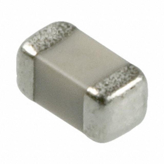
| 描述 | CAP CER 820PF 50V 5% NP0 0603多层陶瓷电容器MLCC - SMD/SMT 50volts 820pF 5% C0G |
| 产品分类 | |
| 品牌 | AVX Corporation |
| 产品手册 | |
| 产品图片 |
|
| rohs | 符合RoHS无铅 / 符合限制有害物质指令(RoHS)规范要求 |
| 产品系列 | MLCC,多层陶瓷电容器MLCC - SMD/SMT,AVX 06035A821JAT2A- |
| 数据手册 | |
| 产品型号 | 06035A821JAT2A |
| 产品 | General Type MLCCs |
| 产品培训模块 | http://www.digikey.cn/PTM/IndividualPTM.page?site=cn&lang=zhs&ptm=21795 |
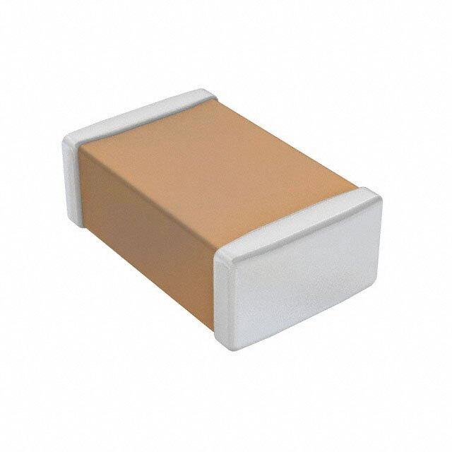
| 产品目录绘图 |
|
| 产品目录页面 | |
| 产品种类 | 多层陶瓷电容器MLCC - SMD/SMT |
| 其它名称 | 478-1186-6 |
| 包装 | Digi-Reel® |
| 厚度(最大值) | 0.035"(0.90mm) |
| 商标 | AVX |
| 外壳代码-in | 0603 |
| 外壳代码-mm | 1608 |
| 外壳宽度 | 0.81 mm |
| 外壳长度 | 1.6 mm |
| 大小/尺寸 | 0.063" 长 x 0.032" 宽(1.60mm x 0.81mm) |
| 安装类型 | 表面贴装,MLCC |
| 容差 | ±5% |
| 封装 | Reel |
| 封装/外壳 | 0603(1608 公制) |
| 封装/箱体 | 0603 (1608 metric) |
| 工作温度 | -55°C ~ 125°C |
| 工作温度范围 | - 55 C to + 125 C |
| 工厂包装数量 | 4000 |
| 应用 | 通用 |
| 引线形式 | - |
| 引线间距 | - |
| 最大工作温度 | + 125 C |
| 最小工作温度 | - 55 C |
| 标准包装 | 1 |
| 温度系数 | C0G,NP0 |
| 温度系数/代码 | +/- 30 PPM / C |
| 特性 | - |
| 电介质 | C0G (NP0) |
| 电压-额定 | 50V |
| 电压额定值 | 50 V |
| 电压额定值DC | 50 V |
| 电容 | 820pF |
| 端接类型 | SMD/SMT |
| 等级 | - |
| 类型 | Commercial Surface Mount Chip |
| 系列 | 0603 |
| 高度-安装(最大值) | - |


- 商务部:美国ITC正式对集成电路等产品启动337调查
- 曝三星4nm工艺存在良率问题 高通将骁龙8 Gen1或转产台积电
- 太阳诱电将投资9.5亿元在常州建新厂生产MLCC 预计2023年完工
- 英特尔发布欧洲新工厂建设计划 深化IDM 2.0 战略
- 台积电先进制程称霸业界 有大客户加持明年业绩稳了
- 达到5530亿美元!SIA预计今年全球半导体销售额将创下新高
- 英特尔拟将自动驾驶子公司Mobileye上市 估值或超500亿美元
- 三星加码芯片和SET,合并消费电子和移动部门,撤换高东真等 CEO
- 三星电子宣布重大人事变动 还合并消费电子和移动部门
- 海关总署:前11个月进口集成电路产品价值2.52万亿元 增长14.8%


PDF Datasheet 数据手册内容提取
C0G (NP0) Dielectric General Specifications C0G (NP0) is the most popular formulation of the “temperature-compensating,” EIA Class I ceramic materials. Modern C0G (NP0) formulations contain neodymium, samarium and other rare earth oxides. C0G (NP0) ceramics offer one of the most stable capacitor dielectrics available. Capacitance change with temperature is 0 ±30ppm/°C which is less than ±0.3% C from -55°C to +125°C. Capacitance drift or hysteresis for C0G (NP0) ceramics is negligible at less than ±0.05% versus up to ±2% for films. Typical capacitance change with life is less than ±0.1% for C0G (NP0), one-fifth that shown by most other dielectrics. C0G (NP0) formulations show no aging characteristics. PART NUMBER (see page 4 for complete part number explanation) 0805 5 A 101 J A T 2 A Size Voltage Dielectric Capacitance Capacitance Failure Terminations Packaging Special (L” x W”) 6.3V = 6 C0G (NP0) = A Code (In pF) Tolerance Rate T = Plated Ni 2 = 7” Reel Code 10V = Z 2 Sig. Digits + B = ±.10 pF (<10pF) A = Not and Sn 4 = 13” Reel A = Std. 2156VV == Y3 Number of Zeros C = ±.25 pF (<10pF) Applicable Contact U = 4mm TR Product 50V = 5 D = ±.50 pF (<10pF) Factory For (01005) 100V = 1 F = ±1% (≥ 10 pF) 1 = Pd/Ag Term 200V = 2 G = ±2% (≥ 10 pF) 7 = Gold Plated 250V = V J = ±5% Contact Factory NOT RoHS 500V = 7 K = ±10% For Multiples COMPLIANT NOTE: Contact factory for availability of Termination and Tolerance Options for Specific Part Numbers. Contact factory for non-specified capacitance values. The Important Information/Disclaimer is incorporated in these specifications by reference and should be reviewed in full before placing any order. 3 022620
C0G (NP0) Dielectric Specifications and Test Methods Parameter/Test NP0 Specification Limits Measuring Conditions Operating Temperature Range -55ºC to +125ºC Temperature Cycle Chamber Capacitance Within specified tolerance Freq.: 1.0 MHz ± 10% for cap ≤ 1000 pF <30 pF: Q≥ 400+20 x Cap Value 1.0 kHz ± 10% for cap > 1000 pF Q ≥30 pF: Q≥ 1000 Voltage: 1.0Vrms ± .2V 100,000MΩ or 1000MΩ - µF, Charge device with rated voltage for 60 ± 5 secs Insulation Resistance whichever is less @ room temp/humidity Charge device with 250% of rated voltage for 1-5 seconds, w/charge and discharge current limited Dielectric Strength No breakdown or visual defects to 50 mA (max) Note: Charge device with 150% of rated voltage for 500V devices. Appearance No defects Deflection: 2mm Capacitance ±5% or ±.5 pF, whichever is greater Test Time: 30 seconds Variation Resistance to Flexure Q Meets Initial Values (As Above) Stresses Insulation ≥ Initial Value x 0.3 Resistance ≥ 95% of each terminal should be covered Dip device in eutectic solder at 230 ± 5ºC for 5.0 Solderability with fresh solder ± 0.5 seconds Appearance No defects, <25% leaching of either end terminal Capacitance ≤ ±2.5% or ±.25 pF, whichever is greater Variation Dip device in eutectic solder at 260ºC for Resistance to Q Meets Initial Values (As Above) 60sec- onds. Store at room temperature Solder Heat for 24 ± 2hours before measuring electrical Insulation Meets Initial Values (As Above) properties. Resistance Dielectric Meets Initial Values (As Above) Strength Appearance No visual defects Step 1: -55ºC ± 2º 30 ± 3 minutes Capacitance ≤ ±2.5% or ±.25 pF, whichever is greater Step 2: Room Temp ≤ 3 minutes Variation Q Meets Initial Values (As Above) Step 3: +125ºC ± 2º 30 ± 3 minutes Thermal Shock Insulation Meets Initial Values (As Above) Step 4: Room Temp ≤ 3 minutes Resistance Dielectric Repeat for 5 cycles and measure after Meets Initial Values (As Above) Strength 24 hours at room temperature Appearance No visual defects Capacitance ≤ ±3.0% or ± .3 pF, whichever is greater Variation Charge device with twice rated voltage in test chamber set at 125ºC ± 2ºC ≥ 30 pF: Q≥ 350 Q for 1000 hours (+48, -0). ≥10 pF, <30 pF: Q≥ 275 +5C/2 Load Life (C=Nominal Cap) <10 pF: Q≥ 200 +10C Remove from test chamber and stabilize at Insulation ≥ Initial Value x 0.3 (See Above) room temperature for 24 hours Resistance before measuring. Dielectric Meets Initial Values (As Above) Strength Appearance No visual defects Capacitance ≤ ±5.0% or ± .5 pF, whichever is greater Variation Store in a test chamber set at 85ºC ± 2ºC/ 85% ± ≥ 30 pF: Q≥ 350 5% relative humidity for 1000 hours Load Q ≥10 pF, <30 pF: Q≥ 275 +5C/2 (+48, -0) with rated voltage applied. Humidity <10 pF: Q≥ 200 +10C Insulation Remove from chamber and stabilize at room Resistance ≥ Initial Value x 0.3 (See Above) temperature for 24 ± 2 hours before measuring. Dielectric Meets Initial Values (As Above) Strength The Important Information/Disclaimer is incorporated in these specifications 4 by reference and should be reviewed in full before placing any order. 051818
C0G (NP0) Dielectric Capacitance Range PREFERRED SIZES ARE SHADED SIZE 0101* 0201 0402 0603 0805 1206 Soldering Reflow Only Reflow Only Reflow/Wave Reflow/Wave Reflow/Wave Reflow/Wave Packaging All Paper All Paper All Paper All Paper Paper/Embossed Paper/Embossed mm 0.40 ± 0.02 0.60 ± 0.09 1.00 ± 0.10 1.60 ± 0.15 2.01 ± 0.20 3.20 ± 0.20 (L) Length (in.) (0.016 ± 0.0008) (0.024 ± 0.004) (0.040 ± 0.004) (0.063 ± 0.006) (0.079 ± 0.008) (0.126 ± 0.008) mm 0.20 ± 0.02 0.30 ± 0.09 0.50 ± 0.10 0.81 ± 0.15 1.25 ± 0.20 1.60 ± 0.20 W) Width (in.) (0.008 ± 0.0008) (0.011 ± 0.004) (0.020 ± 0.004) (0.032 ± 0.006) (0.049 ± 0.008) (0.063 ± 0.008) mm 0.10 ± 0.04 0.15 ± 0.05 0.25 ± 0.15 0.35 ± 0.15 0.50 ± 0.25 0.50 ± 0.25 (t) Terminal (in.) (0.004 ± 0.0016) (0.006 ± 0.002) (0.010 ± 0.006) (0.014 ± 0.006) (0.020 ± 0.010) (0.020 ± 0.010) WVDC 16 25 50 16 25 50 16 25 50 100 200 16 25 50 100 200 250 16 25 50 100 200 250 500 Cap 0.5 A A C C C G G G G J J J J J J J J J J J (pF) 1.0 B A A C C C G G G G J J J J J J J J J J J 1.2 B A A C C C G G G G J J J J J J J J J J J 1.5 B A A C C C G G G G J J J J J J J J J J J 1.8 B A A C C C G G G G J J J J J J J J J J J 2.2 B A A C C C G G G G J J J J J J J J J J J 2.7 B A A C C C G G G G J J J J J J J J J J J 3.3 B A A C C C G G G G J J J J J J J J J J J 3.9 B A A C C C G G G G J J J J J J J J J J J 4.7 B A A C C C G G G G J J J J J J J J J J J 5.6 B A A C C C G G G G J J J J J J J J J J J 6.8 B A A C C C G G G G J J J J J J J J J J J 8.2 B A A C C C G G G G J J J J J J J J J J J 10 B A A C C C G G G G G J J J J J N J J J J J J J 12 B A A C C C G G G G G J J J J J N J J J J J J J 15 B A A C C C G G G G G J J J J J N J J J J J J J 18 B A A C C C G G G G G J J J J J N J J J J J J J 22 B A A C C C G G G G G J J J J J N J J J J J J J 27 B A A C C C G G G G G J J J J J N J J J J J J J 33 B A A C C C G G G G G J J J J J N J J J J J J J 39 B A A C C C G G G G G J J J J J N J J J J J J J 47 B A A C C C G G G G G J J J J J N J J J J J J J 56 B A A C C C G G G G G J J J J J N J J J J J J 68 B A A C C C G G G G G J J J J J N J J J J J J 82 B A A C C C G G G G G J J J J J N J J J J J J 100 B A A C C C G G G G G J J J J J N J J J J J J 120 C C C G G G G G J J J J J N J J J J J J 150 C C C G G G G G J J J J J N J J J J J J 180 C C C G G G G G J J J J J N J J J J J J 220 C C C G G G G G J J J J J N J J J J J M 270 C C C G G G G J J J J J N J J J J J M 330 C C C G G G G J J J J J N J J J J J M 390 C C C G G G G J J J J J J J J J J M 470 C C C G G G G J J J J J J J J J J M 560 C C C G G G G J J J J J J J J J J M 680 C C C G G G G J J J J J J J J J J P 820 C C C G G G G J J J J J J J J J M 1000 C C C G G G G J J J J J J J J J Q 1200 G G G J J J J J J J J J Q 1500 G G G J J J J J J J M Q 1800 G G G J J J N J J M M Q 2200 G G G N N N N J J M P Q 2700 G G G N N N N J J M P Q 3300 G G G P N N N J J M P Q 3900 G G G P P P N J J M P 4700 G G G P P P N J J M P 5600 P P P J J M P 6800 P P P M M M P 8200 P P P M M M P Cap 0.010 P P P P P P P (μF) 0.012 P P P 0.015 P P P 0.018 P P P 0.022 P P P 0.027 0.033 0.039 0.047 0.068 0.082 0.1 WVDC 16 25 50 16 25 50 16 25 50 100 200 16 25 50 100 200 250 16 25 50 100 200 250 500 SIZE 0101* 0201 0402 0603 0805 1206 Letter A B C E G J K M N P Q X Y Z Max. 0.33 0.22 0.56 0.71 0.90 0.94 1.02 1.27 1.40 1.52 1.78 2.29 2.54 2.79 Thickness (0.013) (0.009) (0.022) (0.028) (0.035) (0.037) (0.040) (0.050) (0.05 5) (0.060) (0.070) (0.090) (0.100) (0.110) PAPER EMBOSSED The Important Information/Disclaimer is incorporated in these specifications by reference and should be reviewed in full before placing any order. 5 022720
C0G (NP0) Dielectric Capacitance Range PREFERRED SIZES ARE SHADED SIZE 1210 1812 1825 2220 2225 Soldering Reflow Only Reflow Only Reflow Only Reflow Only Reflow Only Packaging Paper/Embossed All Embossed All Embossed All Embossed All Embossed mm 3.20 ± 0.20 4.50 ± 0.30 4.50 ± 0.30 5.70 ± 0.40 5.72 ± 0.25 (L) Length (in.) (0.126 ± 0.008) (0.177 ± 0.012) (0.177 ± 0.012) (0.225 ± 0.016) (0.225 ± 0.010) mm 2.50 ± 0.20 3.20 ± 0.20 6.40 ± 0.40 5.00 ± 0.40 6.35 ± 0.25 W) Width (in.) (0.098 ± 0.008) (0.126 ± 0.008) (0.252 ± 0.016) (0.197 ± 0.016) (0.250 ± 0.010) mm 0.50 ± 0.25 0.61 ± 0.36 0.61 ± 0.36 0.64 ± 0.39 0.64 ± 0.39 (t) Terminal (in.) (0.020 ± 0.010) (0.024 ± 0.014) (0.024 ± 0.014) (0.025 ± 0.015) (0.025 ± 0.015) WVDC 25 50 100 200 500 25 50 100 200 500 50 100 200 50 100 200 50 100 200 Cap 0.5 (pF) 1.0 1.2 1.5 1.8 2.2 2.7 3.3 3.9 4.7 5.6 6.8 8.2 10 J 12 J 15 J 18 J 22 J 27 J 33 J 39 J 47 J 56 J 68 J 82 J 100 J 120 J 150 J 180 J 220 J 270 J 330 J 390 M 470 M 560 J J J J M 680 J J J K P 820 J J J K P 1000 J J P P P K K N N M M M M M M P 1200 P P P P P K K N N M M M M M M P 1500 P P P P P K K N N M M M M M M P 1800 P P P P P K K N N M M M M M M P 2200 P P P P N K K N N P X X M M M P 2700 P P P P K K N P Q X X M M M P 3300 P P P P K K N P Q X X X X M M P 3900 P P P K K N P Q X X X X M M P 4700 P P P K K N P Y X X X X X X M M P 5600 P P P K K P P Y X X X X X X M M P 6800 P P P K K Q Q X X X X X X M M P 8200 P P K M Q Q X X X X X X M M P Cap 0.010 N N K M Q Q X X X X X X M M P (pF) 0.012 N N K M Q X X X X X X M M P 0.015 P P Q X X X X X X M M Y 0.018 P P Q X X X X X X M M Y 0.022 P P Q X X X X X M Y Y 0.027 Q Q X X X Y X X P Y Y 0.033 Q Q X X X X X X Y Y 0.039 X X X X Y X Y Y 0.047 X X X X Y X Z 0.068 Z Z Y Z X Z 0.082 Z Z Y Z X Z 0.1 Z Z Z Z Z Z WVDC 25 50 100 200 500 25 50 100 200 500 50 100 200 50 100 200 50 100 200 SIZE 1210 1812 1825 2220 2225 Letter A B C E G J K M N P Q X Y Z Max. 0.33 0.22 0.56 0.71 0.90 0.94 1.02 1.27 1.40 1.52 1.78 2.29 2.54 2.79 Thickness (0.013) (0.009) (0.022) (0.028) (0.035) (0.037) (0.040) (0.050) (0.055) (0.060) (0.070) (0.090) (0.100) (0.110) PAPER EMBOSSED The Important Information/Disclaimer is incorporated in these specifications 6 by reference and should be reviewed in full before placing any order. 022720
IMPORTANT INFORMATION/DISCLAIMER All product specifications, statements, information and data (collectively, the “Information”) in this datasheet or made available on the website are subject to change. The customer is responsible for checking and verifying the extent to which the Information contained in this publication is applicable to an order at the time the order is placed. All Information given herein is believed to be accurate and reliable, but it is presented without guarantee, warranty, or responsibility of any kind, expressed or implied. Statements of suitability for certain applications are based on AVX’s knowledge of typical operating conditions for such applications, but are not intended to constitute and AVX specifically disclaims any warranty concerning suitability for a specific customer application or use. ANY USE OF PRODUCT OUTSIDE OF SPECIFICATIONS OR ANY STORAGE OR INSTALLATION INCONSISTENT WITH PRODUCT GUIDANCE VOIDS ANY WARRANTY. The Information is intended for use only by customers who have the requisite experience and capability to determine the correct products for their application. Any technical advice inferred from this Information or otherwise provided by AVX with reference to the use of AVX’s products is given without regard, and AVX assumes no obligation or liability for the advice given or results obtained. Although AVX designs and manufactures its products to the most stringent quality and safety standards, given the current state of the art, isolated component failures may still occur. Accordingly, customer applications which require a high degree of reliability or safety should employ suitable designs or other safeguards (such as installation of protective circuitry or redundancies) in order to ensure that the failure of an electrical component does not result in a risk of personal injury or property damage. Unless specifically agreed to in writing, AVX has not tested or certified its products, services or deliverables for use in high risk applications including medical life support, medical device, direct physical patient contact, water treatment, nuclear facilities, weapon systems, mass and air transportation control, flammable environments, or any other potentially life critical uses. Customer understands and agrees that AVX makes no assurances that the products, services or deliverables are suitable for any high-risk uses. Under no circumstances does AVX warrant or guarantee suitability for any customer design or manufacturing process. Although all product–related warnings, cautions and notes must be observed, the customer should not assume that all safety measures are indicted or that other measures may not be required. The Important Information/Disclaimer is incorporated in these specifications by reference and should be reviewed in full before placing any order. 121119