ICGOO在线商城 > 分立半导体产品 > 晶闸管 - TRIAC > Q6006LTH

 Datasheet下载
- 型号: Q6006LTH
- 制造商: Littelfuse
- 库位|库存: xxxx|xxxx
- 要求:
| 数量阶梯 | 香港交货 | 国内含税 |
| +xxxx | $xxxx | ¥xxxx |
查看当月历史价格
查看今年历史价格
Q6006LTH产品简介:
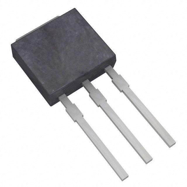
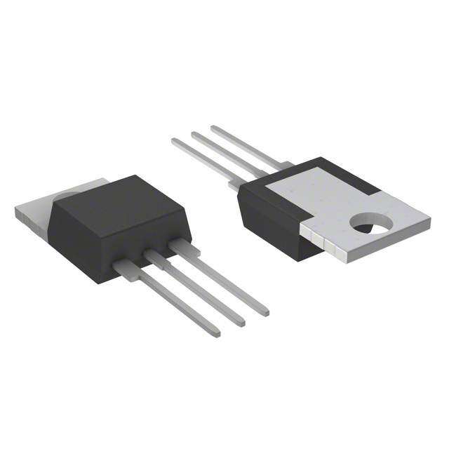
ICGOO电子元器件商城为您提供Q6006LTH由Littelfuse设计生产,在icgoo商城现货销售,并且可以通过原厂、代理商等渠道进行代购。 Q6006LTH价格参考。LittelfuseQ6006LTH封装/规格:晶闸管 - TRIAC, TRIAC Internally Triggered 600V 6A Through Hole TO-220 Isolated Tab。您可以下载Q6006LTH参考资料、Datasheet数据手册功能说明书,资料中有Q6006LTH 详细功能的应用电路图电压和使用方法及教程。
| 参数 | 数值 |
| 产品目录 | |
| 描述 | TRIAC INT TRIGGER 600V 6A TO220双向可控硅 600V 6A 33/43V |
| 产品分类 | 双向可控硅分离式半导体 |
| GateTriggerCurrent-Igt | 1.5 A |
| 品牌 | Littelfuse |
| 产品手册 | |
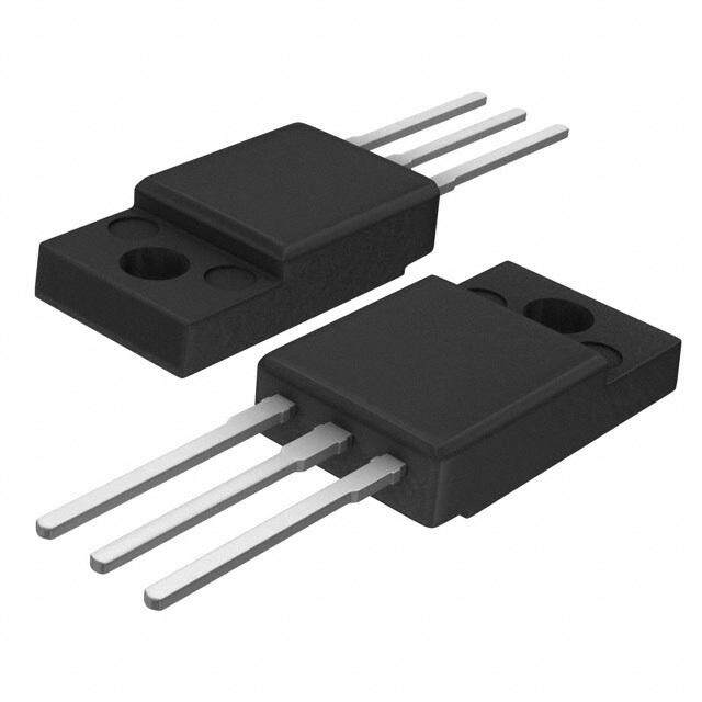
| 产品图片 |
|
| rohs | 符合RoHS无铅 / 符合限制有害物质指令(RoHS)规范要求 |
| 产品系列 | 晶体闸流管,双向可控硅,Littelfuse Q6006LTH- |
| 数据手册 | |
| 产品型号 | Q6006LTH |
| 三端双向可控硅类型 | 内部触发 |
| 不重复通态电流 | 65 A, 80 A |
| 产品种类 | 双向可控硅 |
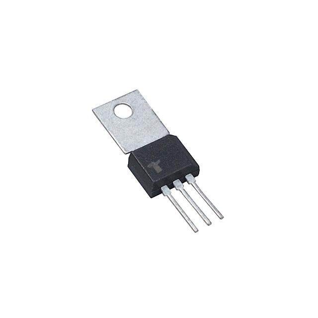
| 供应商器件封装 | TO-220 隔离的标片 |
| 保持电流Ih最大值 | 50 mA |
| 关闭状态漏泄电流(在VDRMIDRM下) | 50 uA |
| 关闭状态电容CO | 0.1 uF |
| 包装 | 散装 |
| 商标 | Littelfuse |
| 安装类型 | 通孔 |
| 安装风格 | Through Hole |
| 封装 | Bulk |
| 封装/外壳 | TO-220-3 隔离片 |
| 封装/箱体 | TO-220-3 |
| 工厂包装数量 | 500 |
| 开启状态RMS电流-ItRMS | 6 A |
| 开启状态电压 | 1.6 V |
| 最大工作温度 | + 125 C |
| 最大转折电流IBO | 25 uA |
| 最小工作温度 | - 40 C |
| 栅极触发电流-Igt | 1.5 A |
| 标准包装 | 500 |
| 电压-断态 | 600V |
| 电压-栅极触发(Vgt)(最大值) | - |
| 电流-不重复浪涌50、60Hz(Itsm) | 65A,80A |
| 电流-保持(Ih)(最大值) | 50mA |
| 电流-栅极触发(Igt)(最大值) | - |
| 电流-通态(It(RMS))(最大值) | 6A |
| 系列 | QxxxxLTx |
| 转折电流VBO | 33 V to 43 V |
| 配置 | 单一 |
| 额定重复关闭状态电压VDRM | 600 V |


- 商务部:美国ITC正式对集成电路等产品启动337调查
- 曝三星4nm工艺存在良率问题 高通将骁龙8 Gen1或转产台积电
- 太阳诱电将投资9.5亿元在常州建新厂生产MLCC 预计2023年完工
- 英特尔发布欧洲新工厂建设计划 深化IDM 2.0 战略
- 台积电先进制程称霸业界 有大客户加持明年业绩稳了
- 达到5530亿美元!SIA预计今年全球半导体销售额将创下新高
- 英特尔拟将自动驾驶子公司Mobileye上市 估值或超500亿美元
- 三星加码芯片和SET,合并消费电子和移动部门,撤换高东真等 CEO
- 三星电子宣布重大人事变动 还合并消费电子和移动部门
- 海关总署:前11个月进口集成电路产品价值2.52万亿元 增长14.8%


PDF Datasheet 数据手册内容提取
Teccor® brand Thyristors 4 / 6 / 8 / 10 / 15 Amp Quadracs QxxxxLTx Series RoHS ® Description The Quadrac is an internally triggered Triac designed for AC switching and phase control applications. It is a Triac and DIAC in a single package, which saves user expense by eliminating the need for separate Triac and DIAC components. Standard type devices normally operate in Quadrants I & III triggered from AC line. Alternistor type Quadracs are used in circuits requiring high dv/dt capability. Features & Benefits • RoHS Compliant • Surge capability up to Agency Approval 200 A • Glass – passivated Agency Agency File Number junctions L Package : E71639 • Voltage capability up to ® 600 V Schematic Symbol Applications Excellent for AC switching and phase control applications such as lighting and heating. Typical applications are AC MT2 MT1 solid-state switches, light dimmers, power tools, home/ brown goods and white goods appliances. Alternistor Quadracs (no snubber required) are used in T applications with extremely inductive loads requiring highest commutation performance. Main Features Internally constructed isolated package is offered for ease of heat sinking with highest isolation voltage. Symbol Value Unit I 4 to 15 A T(RMS) V / V 400 to 600 V Additional Information DRM RRM DIAC V 33 to 43 V BO Datasheet Resources Samples © 2014 Littelfuse, Inc. Specifications are subject to change without notice. Revised: 12/14/14
Teccor® brand Thyristors 4 / 6 / 8 / 10 / 15 Amp Quadracs Absolute Maximum Ratings Value Symbol Parameter Qxx04LT Qxx06LT / Qxx06LTH Qxx08LT / Qxx08LTH Qxx10LT / Qxx10LTH Qxx15LT / Qxx15LTH Unit Qxx04LT: T = 95°C C I RMS forward current Qxx06LT/Qxx08LT/Qxx10LT: T = 90°C 4 6 8 10 15 A T(RMS) C Qxx15LT: T = 80°C C single half cycle; f = 50Hz; 46 65 83 100 167 T (initial) = 25°C I Peak non-repetitive surge current J A TSM single half cycle; f = 60Hz; 55 80 100 120 200 T (initial) = 25°C J I2t I2t value for fusing t = 8.3ms 12.5 26.5 41 60 166 A2s p di/dt Critical rate-of-rise of on-state current f = 60Hz; T =125°C 50 70 100 A/µs J I Peak gate current T = 125°C 1.5 A GM J T Storage temperature range -40 to 150 °C stg T Operating junction temperature range -40 to 125 °C J Note: xx = voltage Electrical Characteristics (T = 25°C, unless otherwise specified) – Standard Quadrac J Value T T T T T Symbol Test Conditions 4L 6L 8L 0L 5L Unit 0 0 0 1 1 x x x x x x x x x x Q Q Q Q Q I I = 200mA (initial) MAX. 40 50 60 60 70 mA H T 400V 75 150 175 200 300 V = V ; gate open; T=100°C MIN. D DRM J 600V 50 125 150 175 200 dv/dt V/μs 400V 50 100 120 150 200 V = V ; gate open; T=125°C MIN. D DRM J 600V 50 85 100 120 150 dv/dt(c) di/dt(c) = 0.54 x I / ms; T = 125°C MIN. 3 4 V/μs T(rms) J t (note 1) TYP. 3 μs gt (1) Reference test circuit in figure 10 and waveform in figure 11; C = 0.1μF with 0.1μs rise time. T Note: xx = voltage Electrical Characteristics (T = 25°C, unless otherwise specified) – Alternistor Quadrac J Value H H H H Symbol Test Conditions LT LT LT LT Unit 6 8 0 5 0 0 1 1 x x x x x x x x Q Q Q Q I I = 20mA (initial) MAX. 50 50 60 70 mA H T 400V 575 925 V = V ; gate open; T=100°C MIN. D DRM J 600V 425 775 dv/dt V/μs 400V 450 700 V = V ; gate open; T=125°C MIN. D DRM J 600V 350 600 dv/dt(c) di/dt(c) = 0.54 x I / ms; T = 125°C MIN. 25 30 V/μs T(rms) J t (note 1) TYP. 3 μs gt (1) Reference test circuit in figure 10 and waveform in figure 11; C = 0.1μF with 0.1μs rise time. T Note: xx = voltage © 2014 Littelfuse, Inc. Specifications are subject to change without notice. Revised: 12/14/14
Teccor® brand Thyristors 4 / 6 / 8 / 10 / 15 Amp Quadracs Trigger DIAC Specifications Symbol Test Conditions Value Unit ΔV Breakover Voltage Symmetry MAX. 3 V BO MIN. 33 V Breakover Voltage, forward and reverse V BO MAX. 43 [ΔV±] Dynamic Breakback Voltage, forward and reverse (note 1) MIN. 5 V I Peak Breakover Current MAX. 25 uA BO C Trigger Firing Capacitance MAX. 0.1 µF T (1) Reference test circuit in figure 10 and waveform in figure 11. Static Characteristics Symbol Test Conditions Value Unit V I = 1.41 x I A; t = 380μs MAX. 1.6 V TM T T(rms) p T = 25°C 10 J I / I V / V T = 100°C MAX. 500 µA DRM RRM DRM RRM J T = 125°C 2000 J Thermal Resistances Symbol Parameter Value Unit Qxx04LT 3.6 Qxx06LT / 3.3 Qxx06LTH Qxx08LT / 2.8 R Junction to case (AC) Qxx08LTH °C/W θ(J-C) Qxx10LT / 2.6 Qxx10LTH Qxx15LT / 2.1 Qxx15LTH R Junction to ambient 50 °C/W θ(J-A) Note : xx = voltage © 2014 Littelfuse, Inc. Specifications are subject to change without notice. Revised: 12/14/14
Teccor® brand Thyristors 4 / 6 / 8 / 10 / 15 Amp Quadracs Figure 1: Normalized DC Holding Current Figure 2: On-State Current vs. On-State Voltage vs. Junction Temperature (Typical) (4A) 2.0 s 16 p m – A 14 TJ = 25°C C) 1.5 nt (i) T12 o of I/I(T = 25°HHJ1.0 us On-state Curre 1068 Qxx04LT Rati 0.5 aneo 4 nt 2 a st In 0 0.7 0.8 0.9 1.0 1.1 1.2 1.3 1.4 1.5 1.6 0.0 Instantaneous On-state Voltage (v) – Volts -40 -15 10 35 60 85 110 T Junction Temperature (T) -- °C J Figure 3: On-State Current vs. On-State Voltage Figure 4: Power Dissipation vs. RMS On-State (Typical) (6A to 15A) Current (Typical) (4A) s50 4.0 p m45 T = 25°C A J 3.5 ntaneous On-state Current (i) – T11223340505050 QQxxxx1155LLTTHQQQxxxxxx001680LLLTTT///QQQxxxxxx001680LLLTTTHHH Average On-State Power Dissipation [P] - (Watts)D(AV)11223.....05050 QCxUxR0R4LETNT WAVEFORM: Sinusoidal nsta 5 0.5 LCOOANDD:U RCeTsIiOstNiv eA NorG ILnEd:u 3c6ti0v°e I 0 0.0 0.7 0.8 0.9 1.0 1.1 1.2 1.3 1.4 1.5 1.6 1.7 0.0 0.5 1.0 1.5 2.0 2.5 3.0 3.5 4.0 Instantaneous On-state Voltage (vT) – Volts RMS On-State Current [IT(RMS)] - (Amps) Figure 5: Power Dissipation vs. RMS On-State Current Figure 6: Maximum Allowable Case Temperature (Typical) (6A to 15A) vs. RMS On-State Current 18 130 e pation 1146 peratur 120 QQxxxx0088LLTTH CLCOUOARNDRD:EU RNCeTTs IWiOstANivV AeE NoFrGO ILRnEMd:u :1 cS8t0iinv°eusoidal ge On-State Power Dissi[P] - (Watts)D(AV)1102468 QQQxxxxxx001680LLLTTT///QQQxxxxxx001680LLLTTTHHH QQxxxx1155LLTTH um Allowable Case Tem(T) - °CC11901000 Qxx04LQTxx06LT QQxxxx1100LLTTH QQxxxx1155LLTTH a m Qxx06LTH Aver 2 CLCOUOARNDRD:EU RNCeTTs IWiOstANivV eAE NoFrGO ILRnEdM:u :3c S6ti0ivn°eusoidal Maxi 80 0 70 0 2 4 6 8 10 12 14 16 0 2 4 6 8 10 12 14 16 RMS On-State Current [I ] - (Amps) RMS On-State Current [I ] - Amps T(RMS) T(RMS) © 2014 Littelfuse, Inc. Specifications are subject to change without notice. Revised: 12/14/14
Teccor® brand Thyristors 4 / 6 / 8 / 10 / 15 Amp Quadracs Figure 7: Surge Peak On-State Current vs. Number of Cycles 1000 Supply Frequency: 60Hz Sinusoidal Load: Resistive RMS On-State Current: [I ]: Maximum Rated T(RMS) s Qxx15LT/Qxx15LTH Value at Specific Case Temperature e) mp petitiv ) – AM100 Qxx10LT/Qxx10LTH Qxx08LT/Qxx08LTH N1.o Gteast:e control may be lost during and immediately on-re nt (ITS 2. f Oovlleorwloinadg msuaryg en octu rbree nret pinetaetrevda l.until junction N e e ( urr temperature has returned to steady-state g C Qxx06LT/Qxx06LTH rated value. eak Sur n-state 10 Qxx04LT P O 1 1 10 100 1000 Surge Current Duration -- Full Cycles Note: xx = voltage Figure 8: DIAC V Change vs. Junction Temperature Figure 9: Test Circuit BO 4% 2% R L % 0% e -- 120 V D.U.T. MT2 ng -2% 60 Hz a h C V BO -4% -6% T -8% V C MT1 10% C = 0.1 µF -40 -20 0 20 40 60 80 100 120 T Junction Temperature (T) -- °C J Figure 10: Test Circuit Waveform Figure 11: Peak Output Current vs Triggering Capacitance (Per Figure 9) V C +V 300 BO A ∆V+ m 0 t ent (I) – PK220500 -VBOIL ∆V- Output Curr 110500 Typical (35V Device) +IPK ak e P 50 0 t 0 0.1 0.2 0.3 0.4 0.5 0.6 0.7 0.8 0.9 1.0 -I PK Triggering Capacitance (C) – μF Typical pulse base width is 10μs T © 2014 Littelfuse, Inc. Specifications are subject to change without notice. Revised: 12/14/14
Teccor® brand Thyristors 4 / 6 / 8 / 10 / 15 Amp Quadracs Soldering Parameters Reflow Condition Pb – Free assembly t P T P - Temperature Min (Ts(min)) 150°C e RRaammpp--uupp Pre Heat -- TTeimmep e(mraitnu rteo Mmaaxx )( T(ts()max)) 2600 0–° C180 secs rutare TS(mTaxL) tL s p m RRaammpp--ddoown Average ramp up rate (Liquidus Temp) PPrreehheeaatt (TL) to peak 5°C/second max eT TS(min) t T to T - Ramp-up Rate 5°C/second max S S(max) L - Temperature (T) (Liquidus) 217°C Reflow L 25 - Temperature (tL) 60 – 150 seconds time to peak temperature Time Peak Temperature (T) 260+0/-5 °C P Time within 5°C of actual peak 20 – 40 seconds Temperature (t) p Ramp-down Rate 5°C/second max Time 25°C to peak Temperature (T) 8 minutes Max. P Do not exceed 280°C Physical Specifications Environmental Specifications Test Specifications and Conditions Terminal Finish 1005 Matte Tin-plated MIL-STD-750: Method 1040, Condition A High Temperature Rated V (VAC-peak), 125°C, 1008 Voltage Blocking DRM UL Recognized epoxy meeting hours Body Material flammability classification 94v-0 MIL-STD-750: Method 1051 Temperature Cycling -40°C to 150°C, 15-minute dwell, 100 cycles Lead Material Copper Alloy Biased Temperature & EIA/JEDEC: JESD22-A101 Humidity 320VDC, 85°C, 85%RH, 1008 hours MIL-STD-750: Method 1031 High Temp Storage Design Considerations 150°C, 1008 hours Careful selection of the correct device for the application’s Low-Temp Storage -40°C, 1008 hours operating parameters and environment will go a long way MIL-STD-750: Method 1056 toward extending the operating life of the Thyristor. Good Thermal Shock 0°C to 100°C, 5-minute dwell, design practice should limit the maximum continuous 10-second transfer, 10 cycles current through the main terminals to 75% of the device Autoclave EIA/JEDEC: JESD22-A102 rating. Other ways to ensure long life for a power discrete (Pressure Cooker Test) 121°C, 100%RH, 2atm, 168 hours semiconductor are proper heat sinking and selection of Resistance to MIL-STD-750: Method 2031 voltage ratings for worst case conditions. Overheating, Solder Heat 260°C, 10 seconds overvoltage (including dv/dt), and surge currents are Solderability ANSI/J-STD-002, Category 3, Test A the main killers of semiconductors. Correct mounting, soldering, and forming of the leads also help protect Lead Bend MIL-STD-750: Method 2036, Condition E against component damage. © 2014 Littelfuse, Inc. Specifications are subject to change without notice. Revised: 12/14/14
Teccor® brand Thyristors 4 / 6 / 8 / 10 / 15 Amp Quadracs Dimensions — TO-220AB (L-Package) — Isolated Mounting Tab TC MEASURING POINT Inches Millimeters O Dimension E A P .83.2130 Min Max Min Max B A 0.380 0.420 9.65 10.67 C AREA (REF.) 0.17 in2 13.36 B 0.105 0.115 2.67 2.92 D .526 C 0.230 0.250 5.84 6.35 7.01 .276 D 0.590 0.620 14.99 15.75 E 0.142 0.147 3.61 3.73 F F 0.110 0.130 2.79 3.30 G R G 0.540 0.575 13.72 14.61 L H 0.025 0.035 0.64 0.89 H J 0.195 0.205 4.95 5.21 K N K 0.095 0.105 2.41 2.67 J M MT1 MT2 T (Trigger) Note: Maximum torque L 0.060 0.075 1.52 1.91 to be applied to mounting tab is 8 in-lbs. (0.904 Nm). M 0.085 0.095 2.16 2.41 N 0.018 0.024 0.46 0.61 O 0.178 0.188 4.52 4.78 P 0.045 0.060 1.14 1.52 R 0.038 0.048 0.97 1.22 Product Selector Voltage Part Number Type Package 400V 600V 800V 1000V Qxx04LT X X Quadrac TO-220L Qxx06LT X X Quadrac TO-220L Qxx06LTH X X Alternistor Quadrac TO-220L Qxx08LT X X Quadrac TO-220L Qxx08LTH X X Alternistor Quadrac TO-220L Qxx10LT X X Quadrac TO-220L Qxx10LTH X X Alternistor Quadrac TO-220L Qxx15LT X X Quadrac TO-220L Qxx15LTH X X Alternistor Quadrac TO-220L Note: xx = Voltage © 2014 Littelfuse, Inc. Specifications are subject to change without notice. Revised: 12/14/14
Teccor® brand Thyristors 4 / 6 / 8 / 10 / 15 Amp Quadracs Packing Options Part Number Marking Weight Packing Mode Base Quantity Qxx04LT Qxx04LT 2.2 g Bulk 500 Qxx04LTTP Qxx04LT 2.2 g Tube 500 (50 per tube) Qxx06LT Qxx06LT 2.2 g Bulk 500 Qxx06LTTP Qxx06LT 2.2 g Tube 500 (50 per tube) Qxx06LTH Qxx06LTH 2.2 g Bulk 500 Qxx06LTHTP Qxx06LTH 2.2 g Tube 500 (50 per tube) Qxx08LT Qxx08LT 2.2 g Bulk 500 Qxx08LTTP Qxx08LT 2.2 g Tube 500 (50 per tube) Qxx08LTH Qxx08LTH 2.2 g Bulk 500 Qxx08LTHTP Qxx08LTH 2.2 g Tube 500 (50 per tube) Qxx10LT Qxx10LT 2.2 g Bulk 500 Qxx10LTTP Qxx10LT 2.2 g Tube 500 (50 per tube) Qxx10LTH Qxx10LTH 2.2 g Bulk 500 Qxx10LTHTP Qxx10LTH 2.2 g Tube 500 (50 per tube) Qxx15LT Qxx15LT 2.2 g Bulk 500 Qxx15LTTP Qxx15LT 2.2 g Tube 500 (50 per tube) Qxx15LTH Qxx15LTH 2.2 g Bulk 500 Qxx15LTHTP Qxx15LTH 2.2 g Tube 500 (50 per tube) Note: xx = Voltage Part Numbering System Part Marking System Q 60 10 L T H 56 TO-220 AB - (L Package) DEVICE TYPE Q: Quadrac LEAD FORM DIMENSIONS xx: Lead Form Option VOLTAGE RATING 40: 400V TRIAC TYPE Q6010LTH 60: 600V (blank): Standard Triac YMXXX H: Alternistor Triac Trigger CURRENT RATING T: Internal Diac (33V –43V) ® 04: 4A 06: 6A PACKAGE TYPE 08: 8A L: TO-220 (Isolated) 10: 10A 15: 15A Date Code Marking Y:Year Code M: Month Code XXX: Lot Trace Code © 2014 Littelfuse, Inc. Specifications are subject to change without notice. Revised: 12/14/14